Embed Size (px)
Citation preview
1 3
Microsyst TechnolDOI 10.1007/s00542-016-3193-8
TECHNICAL PAPER
Photoelectrocatalytic microreactor for seawater decontamination with negligible chlorine generation
Ning Wang1,2,3,4 · Furui Tan3,4 · Chi Chung Tsoi3,4 · Xuming Zhang3,4
Received: 31 August 2016 / Accepted: 4 November 2016 © Springer-Verlag Berlin Heidelberg 2016
bias and about 4.7 s−1 for the positive bias while the gener-ated chlorine is negligible with bias up to 2.2 V. The high decontamination efficiency and elimination of chlorine generation suggest that the photoelectrocatalytic microre-actor device has high potential to be scaled up for indus-trial applications. This also provides us an ideal platform to study the underling mechanisms and kinetics of seawater decontamination.
1 Introduction
Water shortages and pollution is a global problem, even in the areas with abundant water resources. Clean water is needed by human for different purposes: agriculture, indus-try, life and recreation. As we all know, seawater accounts for 97% for the earth’s water and leaves only 3% for the fresh water (Orlove and Caton 2010; Principles et al. 2010; Sultana 2011; Mo and Zhang 2013). The crisis of water resource presents unprecedented demand for desalination and purification of seawater, although the fresh water can be renewable. Actually, many physical and chemical meth-ods have been used in sewage treatment, such as boiling, adsorption, UV treatment, filtration and so on (Ambashta and Sillanpää 2010; Dhakras 2011). Among them, photoca-talysis appears to be a promising technology for water treat-ment by using the photo-excited holes and electrons on the surface of semiconductor photocatalyst to decompose the toxic organic compounds. Up to now, most of the available studies of wastewater treatment focus on waste fresh water. The seawater decontamination has drawn little attention as it duly deserves. The waste seawater comes from flush-ing toilet (like in Hong Kong, seawater is used for flushing the toilet), mariculture, aquaria and seafood wet markets. Removal of organic contaminants is one of the most urgent
Abstract Decontamination of seawater is of particular importance for the waste seawater treatment before its drainage. However, some mature methods to clean waste fresh water cannot be employed to treat waste seawater due to its high slat concentration. Besides, excessive chlorine generation during the seawater decontamination process is toxic for sea creatures. In this work, a microfluidic reactor is designed and fabricated to enable the photoelectrocata-lytic effect for highly-efficient seawater decontamination with negligible chlorine production. The fabricated micro-reactor consists of three layers: a blank indium tin oxide glass (ITO) slide serves as the cover, another ITO glass slide coated with the BiVO4 nanoporous film works as the substrate, and in between is an epoxy layer with a planar reaction chamber (10 × 10 × 0.1 mm3) and a tree-shape microchannel array. Different bias potentials are applied across the reaction chamber to decompose the methylene blue in the saline water. With the bias of ±1.8 V, the degra-dation rate reaches as high as about 5.3 s−1 for the negative
* Ning Wang [email protected]
* Xuming Zhang [email protected]
1 National Engineering Laboratory for Fiber Optic Sensing Technology, Wuhan University of Technology, Wuhan 430070, People’s Republic of China
2 Key Laboratory of Fiber Optic Sensing Technology and Information Processing, Ministry of Education, Wuhan University of Technology, Wuhan 430070, People’s Republic of China
3 The Hong Kong Polytechnic University Shenzhen Research Institute, Shenzhen, People’s Republic of China
4 Department of Applied Physics, The Hong Kong Polytechnic University, Hong Kong, People’s Republic of China
Microsyst Technol
1 3
issues of seawater decontamination (Shimizu and Li 2005). However, seawater decontamination by utilizing of photo-electrocatalytic (PEC) technology is less reported currently.
As a special heterogeneous photocatalysis system, the PEC reactors introduce an electric field in addition to the light irradiation (Wang et al. 2012), which enables the pho-toelectrochemical reaction, not just the photocatalytic reac-tion induced by photon-excited holes and electrons. The provided electric field can effectively suppress the recom-bination of the photo-generated electrons and holes. As a consequence, additional oxygen as an electron acceptor can be supplied during this process. Therefore, the PEC is a promising method for water purification. Some PEC reactors were sugested for water treatment. In our previous study (Wang et al. 2012, 2014b), a PEC microreactor was designed to decompose the methylene blue. The fabricated PEC reactor demonstrated various advantages, such as fast mass transfer, high photon utilization efficiency, easy con-trol of oxidation pathway, avoiding the oxygen deficiency problem, etc. However, when a PEC system used for sea-water decontamination, it may cause secondary pollution (chloride pollution) under higher bias potential. As previ-ously reported, the chloride ion concentration in seawater could reach up to 19 g L−1 when the potential exceeded 1.36 V. A large amount of chlorine ions will be transformed into chlorine (Schmittinger et al. 2000; Deborde and von Gunten 2008), which goes against the seawater recycling because of its strong oxidizability (Winder 2001). There-fore, it is necessary to reduce the chlorine in the process of seawater decontamination (von Sperling 2007).
In this paper, we designed and fabricated a PEC micro-reactor to decompose the methylene blue in salted water environment. For the experiment, the bias potentials between 1.5 and 2.2 V were applied to the microreactor. The experimental results showed that the chlorine pro-duced in this microreactor was negligible. This provides us a practical way to employ this kind of PEC microreactor for organic degradation of seawater decontamination under relatively high bias potential.
2 Experiment
2.1 Device design and setup
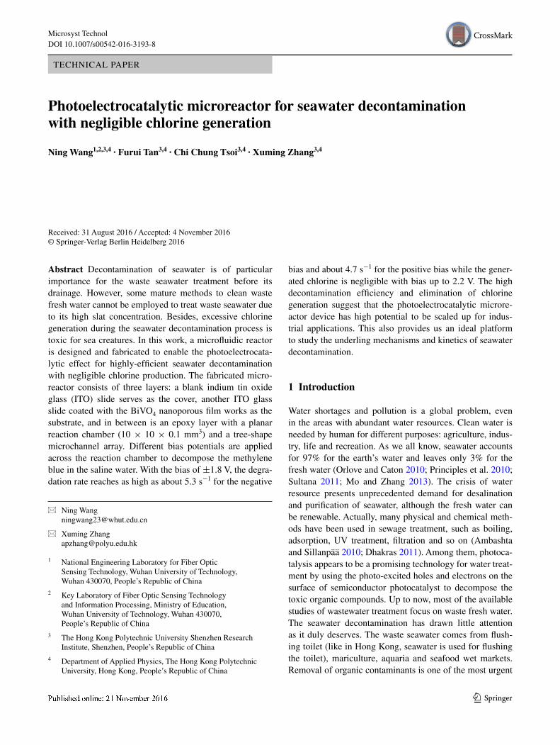
Figure 1 shows the 3D diagram of the PEC microreac-tor consisting of three layers. Two pieces of indium tin oxide (ITO) glass slides serve as the cover and the sub-strate, respectively, A NOA 81 adhesive layer with reac-tion chamber is sandwiched by the two ITO layers. The microchannels work as the spacer and sealant. In the reaction chamber, a BiVO4 (BVO) thin film is synthe-sized and fabricated on the ITO substrate and acts as
the visible-light photocatalyst (the yellow square area). The external bias potential can be applied to the reac-tion chamber through the two ITO layers which serve as the top and bottom electrodes. The seawater pollution samples are pumped in from the inlet, through the reac-tion chamber and out from the outlet. During its flowing across the chamber, the reaction occurs with the light irradiation simultaneously.
The standard UV lithography technology is employed to fabricate the SU-8 micro pattern on silicon wafer. Then PDMS mold with micro structure is reverse mould. The NOA 81 adhesive layer embedded with microchannel array and reaction chamber is cured by UV lamp (Lei et al. 2010; Wang et al. 2011, 2012, 2014a, b). The overall footprint of the device is about 40 mm × 25 mm. The reaction chamber
Fig. 1 Three-dimensional diagram of the microfluidic photoelec-trocatalytic reactor. The reactor consists of a blank ITO glass as the cover, a BVO-coated ITO glass as the substrate and a NOA81 adhe-sive layer as the spacer. A potential is applied across the two ITO lay-ers to force the separation of photo-excited electrons and holes and to help degrade the contaminants by electrocatalytic effect
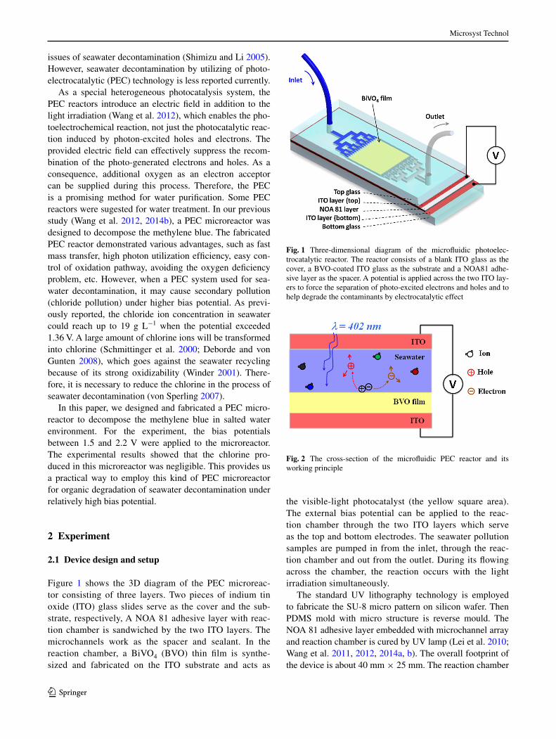
Fig. 2 The cross-section of the microfluidic PEC reactor and its working principle
Microsyst Technol
1 3
is 10 mm × 10 mm × 100 μm (chamber volume 10 μL). Two syringe needles are used as the inlet and outlet.
To simulate the seawater environment, the mixture of methylene blue (MB) (concentration 3 × 10⁻⁵ mol L−1) and NaCl electrolyte solution (0.1 mol L−1) is used as the model chemical for characterizing the photoreactivity. The Na2SO4 electrolyte solution (0.05 mol L−1) is also prepared for the control experiment. A monochromic blue-light LED panel (emission peak: 402 nm) is mounted on the top ITO glass slide as the light source, which lies in the high absorp-tion band of the BVO film. The light intensity illuminated on the reaction chamber is tested to be 80 mW cm−2.
Figure 2 shows the cross section of the PEC microreac-tor. The photo-excited hole and electron will generate on the interface of the seawater sample and photocatatlyst film when the photocatalyst film is irradiated by blue light. The external bias can help the recombination of the electrons and holes and force them to migrate to different directions.
2.2 Fabrication and characterization of BVO film
The fabrication process of BVO film is divided into two steps, BVO nanopowder synthesis and film painting. First, nanosized BVO nanoparticles are synthesized by a solid-phase precipitation preparation method assisted with ultrasonic agitation (Shang et al. 2009). The details can be found in our previous work(Wang et al. 2012). Before the second step, 30 ml BVO sol–gel aqueous solution is pre-pared. This solution includes the grinded BVO powders (3 g) acetylacetone (0.1 mL), Triton X-100 (0.05 mL) and PEG 20000 (0.3 g). After ultrasonic agitation for about 2 h, the manual painting method is followed and the BVO thin film (10 mm × 10 mm) is fabricated onto the ITO glass (Lei et al. 2010). The BVO film is annealed under 500 °C for 2 h in air, then sealed into the reaction chamber. The fabrication and assembly of the PEC microreactor are reported in our previous work (Wang et al. 2012).
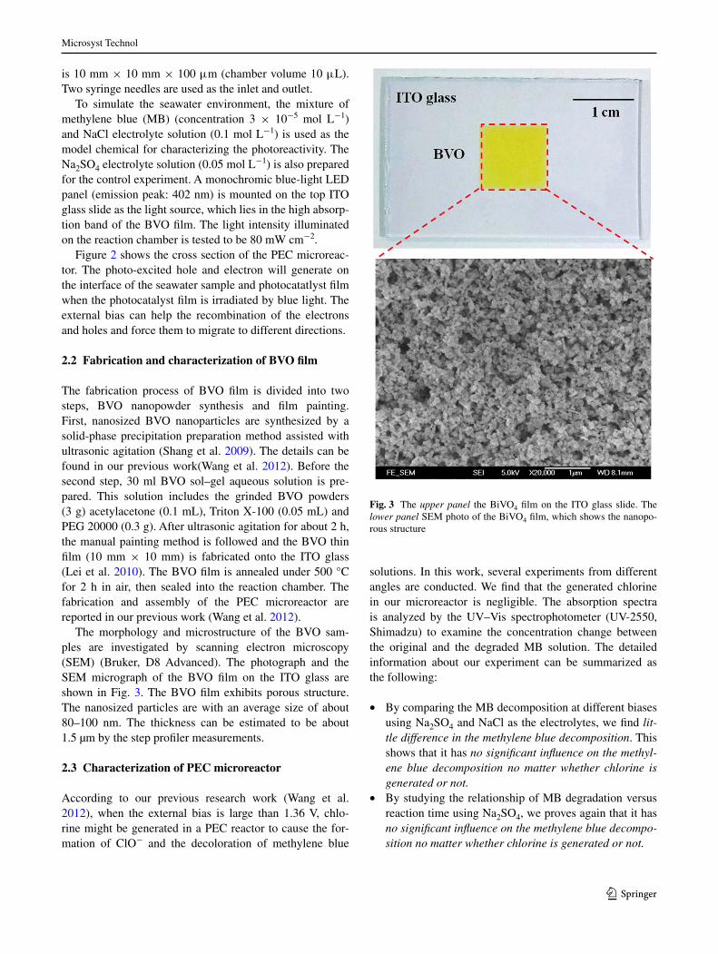
The morphology and microstructure of the BVO sam-ples are investigated by scanning electron microscopy (SEM) (Bruker, D8 Advanced). The photograph and the SEM micrograph of the BVO film on the ITO glass are shown in Fig. 3. The BVO film exhibits porous structure. The nanosized particles are with an average size of about 80–100 nm. The thickness can be estimated to be about 1.5 µm by the step profiler measurements.
2.3 Characterization of PEC microreactor
According to our previous research work (Wang et al. 2012), when the external bias is large than 1.36 V, chlo-rine might be generated in a PEC reactor to cause the for-mation of ClO− and the decoloration of methylene blue
solutions. In this work, several experiments from different angles are conducted. We find that the generated chlorine in our microreactor is negligible. The absorption spectra is analyzed by the UV–Vis spectrophotometer (UV-2550, Shimadzu) to examine the concentration change between the original and the degraded MB solution. The detailed information about our experiment can be summarized as the following:
• By comparing the MB decomposition at different biases using Na2SO4 and NaCl as the electrolytes, we find lit-tle difference in the methylene blue decomposition. This shows that it has no significant influence on the methyl-ene blue decomposition no matter whether chlorine is generated or not.
• By studying the relationship of MB degradation versus reaction time using Na2SO4, we proves again that it has no significant influence on the methylene blue decompo-sition no matter whether chlorine is generated or not.
Fig. 3 The upper panel the BiVO4 film on the ITO glass slide. The lower panel SEM photo of the BiVO4 film, which shows the nanopo-rous structure
Microsyst Technol
1 3
• By measuring the IV curves using cyclic voltammetry, we show quantitatively that there is no significant gen-eration of chlorine in this reaction system.
• By conducting the control experiments using different electrodes, we show that the electrolyzed chlorine is 4 orders smaller than the naturally dissolved oxygen con-tent in the MB solution. This is attributed to the poten-tial drops and the high overpotentials of the ITO and BiVO4 films.
3 Results and discussion
3.1 Decomposing MB by PEC microreactor using Na2SO4 as electrolyte
First, we used Na2SO4 as the electrolyte to replace NaCl for the photodegradation experiments of PEC microreac-tors. The Na2SO4 solution does not generate chlorine in electrolysis. For a fair comparison, both of the Na2SO4 solution and the NaCl solution have the same concentration of Na+ in the methylene blue solutions. As the NaCl solu-tion is 0.1 M in our previous study (Wang et al. 2012), here the Na2SO4 solution is chosen to be 0.05 M in the tests for equal amount of sodium ion.
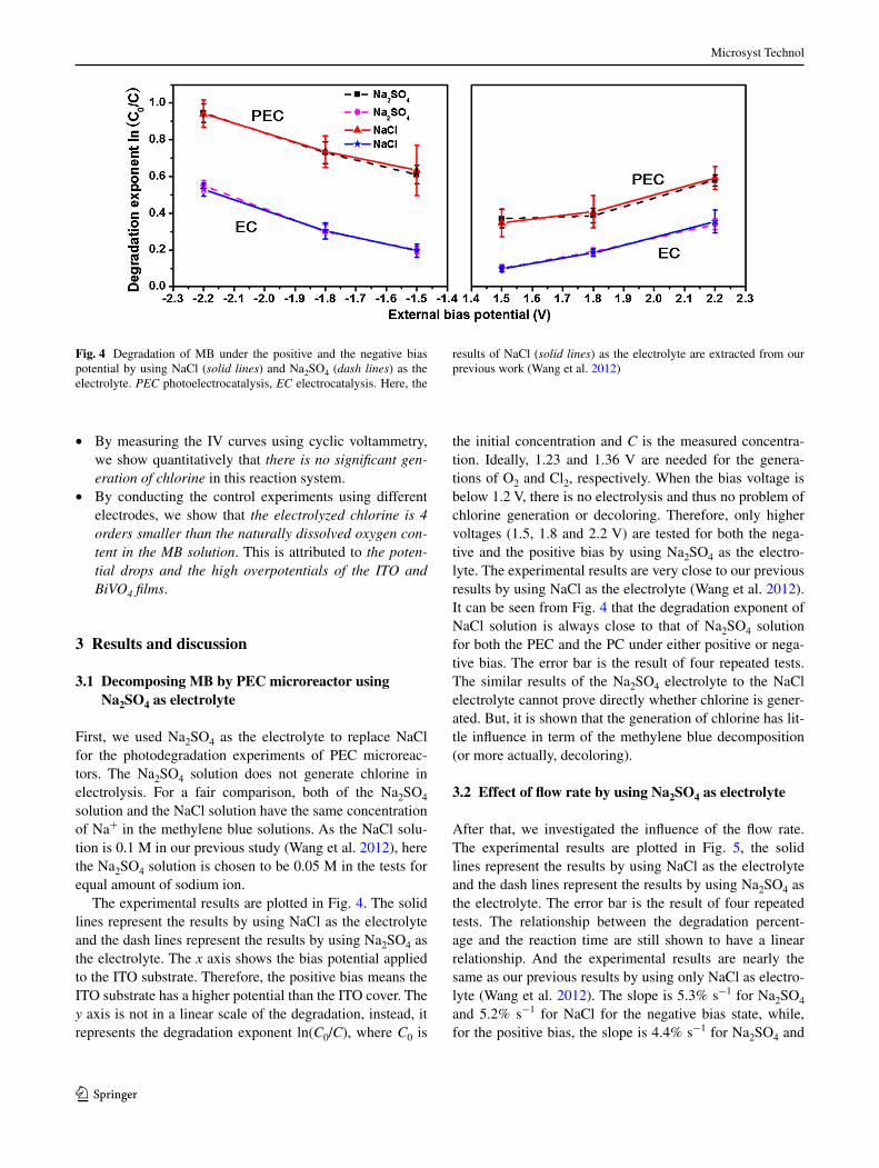
The experimental results are plotted in Fig. 4. The solid lines represent the results by using NaCl as the electrolyte and the dash lines represent the results by using Na2SO4 as the electrolyte. The x axis shows the bias potential applied to the ITO substrate. Therefore, the positive bias means the ITO substrate has a higher potential than the ITO cover. The y axis is not in a linear scale of the degradation, instead, it represents the degradation exponent ln(C0/C), where C0 is
the initial concentration and C is the measured concentra-tion. Ideally, 1.23 and 1.36 V are needed for the genera-tions of O2 and Cl2, respectively. When the bias voltage is below 1.2 V, there is no electrolysis and thus no problem of chlorine generation or decoloring. Therefore, only higher voltages (1.5, 1.8 and 2.2 V) are tested for both the nega-tive and the positive bias by using Na2SO4 as the electro-lyte. The experimental results are very close to our previous results by using NaCl as the electrolyte (Wang et al. 2012). It can be seen from Fig. 4 that the degradation exponent of NaCl solution is always close to that of Na2SO4 solution for both the PEC and the PC under either positive or nega-tive bias. The error bar is the result of four repeated tests. The similar results of the Na2SO4 electrolyte to the NaCl electrolyte cannot prove directly whether chlorine is gener-ated. But, it is shown that the generation of chlorine has lit-tle influence in term of the methylene blue decomposition (or more actually, decoloring).
3.2 Effect of flow rate by using Na2SO4 as electrolyte
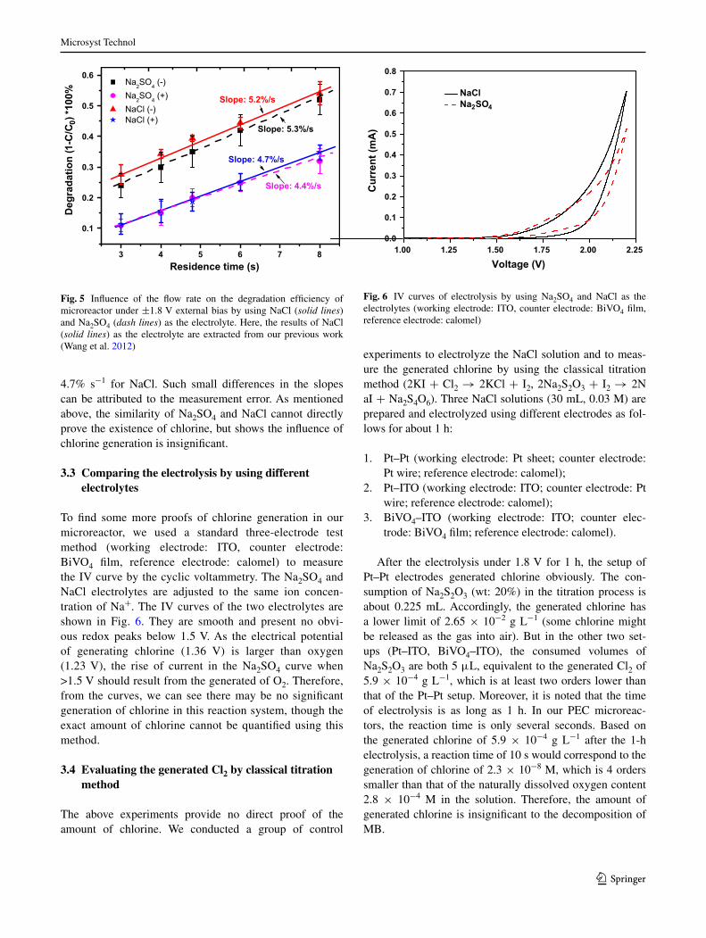
After that, we investigated the influence of the flow rate. The experimental results are plotted in Fig. 5, the solid lines represent the results by using NaCl as the electrolyte and the dash lines represent the results by using Na2SO4 as the electrolyte. The error bar is the result of four repeated tests. The relationship between the degradation percent-age and the reaction time are still shown to have a linear relationship. And the experimental results are nearly the same as our previous results by using only NaCl as electro-lyte (Wang et al. 2012). The slope is 5.3% s−1 for Na2SO4 and 5.2% s−1 for NaCl for the negative bias state, while, for the positive bias, the slope is 4.4% s−1 for Na2SO4 and
Fig. 4 Degradation of MB under the positive and the negative bias potential by using NaCl (solid lines) and Na2SO4 (dash lines) as the electrolyte. PEC photoelectrocatalysis, EC electrocatalysis. Here, the
results of NaCl (solid lines) as the electrolyte are extracted from our previous work (Wang et al. 2012)
Microsyst Technol
1 3
4.7% s−1 for NaCl. Such small differences in the slopes can be attributed to the measurement error. As mentioned above, the similarity of Na2SO4 and NaCl cannot directly prove the existence of chlorine, but shows the influence of chlorine generation is insignificant.
3.3 Comparing the electrolysis by using different electrolytes
To find some more proofs of chlorine generation in our microreactor, we used a standard three-electrode test method (working electrode: ITO, counter electrode: BiVO4 film, reference electrode: calomel) to measure the IV curve by the cyclic voltammetry. The Na2SO4 and NaCl electrolytes are adjusted to the same ion concen-tration of Na+. The IV curves of the two electrolytes are shown in Fig. 6. They are smooth and present no obvi-ous redox peaks below 1.5 V. As the electrical potential of generating chlorine (1.36 V) is larger than oxygen (1.23 V), the rise of current in the Na2SO4 curve when >1.5 V should result from the generated of O2. Therefore, from the curves, we can see there may be no significant generation of chlorine in this reaction system, though the exact amount of chlorine cannot be quantified using this method.
3.4 Evaluating the generated Cl2 by classical titration method
The above experiments provide no direct proof of the amount of chlorine. We conducted a group of control
experiments to electrolyze the NaCl solution and to meas-ure the generated chlorine by using the classical titration method (2KI + Cl2 → 2KCl + I2, 2Na2S2O3 + I2 → 2NaI + Na2S4O6). Three NaCl solutions (30 mL, 0.03 M) are prepared and electrolyzed using different electrodes as fol-lows for about 1 h:
1. Pt–Pt (working electrode: Pt sheet; counter electrode: Pt wire; reference electrode: calomel);
2. Pt–ITO (working electrode: ITO; counter electrode: Pt wire; reference electrode: calomel);
3. BiVO4–ITO (working electrode: ITO; counter elec-trode: BiVO4 film; reference electrode: calomel).
After the electrolysis under 1.8 V for 1 h, the setup of Pt–Pt electrodes generated chlorine obviously. The con-sumption of Na2S2O3 (wt: 20%) in the titration process is about 0.225 mL. Accordingly, the generated chlorine has a lower limit of 2.65 × 10⁻² g L−1 (some chlorine might be released as the gas into air). But in the other two set-ups (Pt–ITO, BiVO4–ITO), the consumed volumes of Na2S2O3 are both 5 μL, equivalent to the generated Cl2 of 5.9 × 10⁻⁴ g L−1, which is at least two orders lower than that of the Pt–Pt setup. Moreover, it is noted that the time of electrolysis is as long as 1 h. In our PEC microreac-tors, the reaction time is only several seconds. Based on the generated chlorine of 5.9 × 10⁻⁴ g L−1 after the 1-h electrolysis, a reaction time of 10 s would correspond to the generation of chlorine of 2.3 × 10⁻⁸ M, which is 4 orders smaller than that of the naturally dissolved oxygen content 2.8 × 10⁻⁴ M in the solution. Therefore, the amount of generated chlorine is insignificant to the decomposition of MB.
3 4 5 6 7 8
0.1
0.2
0.3
0.4
0.5
0.6
Slope: 4.4%/s
Slope: 4.7%/s
Slope: 5.3%/s
Na2SO4 (-) Na2SO4 (+) NaCl (-) NaCl (+)
Deg
rada
tion
(1-C
/C0)
*100
%
Residence time (s)
Slope: 5.2%/s
Fig. 5 Influence of the flow rate on the degradation efficiency of microreactor under ±1.8 V external bias by using NaCl (solid lines) and Na2SO4 (dash lines) as the electrolyte. Here, the results of NaCl (solid lines) as the electrolyte are extracted from our previous work (Wang et al. 2012)
1.00 1.25 1.50 1.75 2.00 2.250.0
0.1
0.2
0.3
0.4
0.5
0.6
0.7
0.8
Cur
rent
(mA
)
Voltage (V)
NaCl Na2SO4
Fig. 6 IV curves of electrolysis by using Na2SO4 and NaCl as the electrolytes (working electrode: ITO, counter electrode: BiVO4 film, reference electrode: calomel)

Microsyst Technol
1 3
This may be explained by the large potential drop and/or high overpotentials by the non-perfect conductive ITO and BiVO4 films. Theoretically, the generations of O2 and Cl2 need 1.23 and 1.36 V, respectively. However, the PEC reactor uses the ITO glass as the working electrode and the semiconducting BiVO4 film as the counter electrode, none of ITO and BiVO4 is highly conductive. They would cause some potential drops, especially for the semiconducting BiVO4 film. In addition, both of the ITO and BiVO4 may require high overpotentials as compared to the Pt electrode. As a result, the bias of 2.2 V is still not high enough to electrolyze chlorine from the NaCl solution.
4 Conclusions
In this work, we have demonstrated that the PEC micro-reactors could solve a fundamental problem of the PEC seawater decontamination, i.e., the generation of chlorine and hypochloric acid. Moreover, the organic contami-nant in seawater can be decomposed by applied a high bias potential 2.2 V. Besides, the problem of chlorine gen-eration in normal PEC reaction system can be reduced or even eliminated under the large bias potential. In addition to the merits of high efficiency and elimination of chlorine generation, the photoelectrocatalytic microreactor exhib-its superior properties, such as fast mass transfer, uniform light irradiation and fine control of reaction conditions (magnitude and polarities of biases, flow rate, easy selec-tive of reaction pathways), making it an ideal platform for the study of mechanisms and kinetics of seawater decon-tamination. It also shows potential applications in large-scale seawater decontamination. This kind of PEC reactors based on microfluidics can provide us opportunity to study the PEC processes of water splitting or/and electricity gen-eration in the environment of seawater.
Acknowledgements This work is supported by National Science Foundation of China (61605148, 61377068 and 61505150), Research Grants Council (RGC) of Hong Kong (N_PolyU505/13, PolyU 5334/12E and PolyU 152184/15E), and The Hong Kong Polytech-nic University (G-YN07, G-YBBE, 4-BCAL, 1-ZVAW, 1-ZE14, A-PM21, 1-ZE27 and 1-ZVGH).
References
Ambashta RD, Sillanpää M (2010) Water purification using magnetic assistance: a review. J Hazard Mater 180:38–49
Deborde M, von Gunten U (2008) Reactions of chlorine with inor-ganic and organic compounds during water treatment-kinetics and mechanisms: a critical review. Water Res 42:13–51
Dhakras PA (2011) Nanotechnology applications in water purification and waste water treatment: a review. Int Conf Nanosci Eng Tech-nol (ICONSET 2011). doi:10.1109/ICONSET.2011.6167965
Lei L, Wang N, Zhang XM et al (2010) Optofluidic planar reactors for photocatalytic water treatment using solar energy. Biomicroflu-idics 4:43004. doi:10.1063/1.3491471
Mo W, Zhang Q (2013) Energy-nutrients-water nexus: integrated resource recovery in municipal wastewater treatment plants. J Environ Manage 127:255–267
Orlove B, Caton SC (2010) Water sustainability: anthropological approaches and prospects. Annu Rev Anthropol 39:401–415. doi:10.1146/annurev.anthro.012809.105045
Principles P, For G, Water I (2010) Water 2015 resource manage-ment—IWRM. Water 27:343–352
Schmittinger P, Florkiewicz T, Curlin LC et al (2000) Chlorine. Ull-mann’s Encycl Ind Chem. doi:10.1002/14356007.a06_399.pub3
Shang M, Wang W, Zhou L et al (2009) Nanosized BiVO4 with high visible-light-induced photocatalytic activity: ultrasonic-assisted synthesis and protective effect of surfactant. J Hazard Mater 172:338–344. doi:10.1016/j.jhazmat.2009.07.017
Shimizu Y, Li B (2005) Purification of water-soluble natural products. Nat Prod Isol 20:415–438
Sultana F (2011) Suffering for water, suffering from water: emotional geographies of resource access, control and conflict. Geoforum 42:163–172. doi:10.1016/j.geoforum.2010.12.002
Von Sperling M (2007) Biological wastewater treatment vol. 2: basic principles of wastewater treatment. Iwa Publishing, United Kingdom
Wang N, Lei L, Zhang XM et al (2011) A comparative study of prepa-ration methods of nanoporous TiO2 films for microfluidic pho-tocatalysis. Microelectron Eng 88:2797–2799. doi:10.1016/j.mee.2010.12.051
Wang N, Zhang X, Chen B et al (2012) Microfluidic photoelectrocata-lytic reactors for water purification with an integrated visible-light source. Lab Chip 12:3983
Wang N, Tan F, Wan L et al (2014a) Microfluidic reactors for visible-light photocatalytic water purification assisted with thermolysis. Biomicrofluidics 8:54122. doi:10.1063/1.4899883
Wang N, Zhang X, Wang Y et al (2014b) Microfluidic reactors for photocatalytic water purification. Lab Chip 14:1074–1082. doi:10.1039/c3lc51233a
Winder C (2001) The toxicology of chlorine. Environ Res 85:105–114. doi:10.1006/enrs.2000.4110