Embed Size (px)
Citation preview

Requirements such asextremely tight mountingspaces under the mostdifficult of conditionsare easily handled by thesub-mini BOS 2K.
The electronic circuitry ishoused in a plastic enclosurejust 20.6×12.5×7.6 mm.Metal sleeves in the housingensure secure and simplemounting.
The laser-like, visible lightspot makes precise small-parts detection possible.
Unmatched ranges upto 1.2 m and fast responsetimes ensure compatibilitywith dynamic applications.
The BOS 2K series is acomplete family with diffuse,retroreflective andthrough-beam models, aswell as diffuse withbackground suppression.That means this series offersthe complete functionalitydemanded of a modernsensor family.
2.1.100
BOS 2KPhotoelectricSensors

PhotoelectricSensorsAccessoriesPage 2.3.2 ...
2.1
2.3
Type
Diffuse with HGABOS 2K-PS-RH10-00,2-S49BOS 2K-PO-RH10-00,2-S49BOS 2K-PS-RH10-00,2-S75BOS 2K-PS-RH10-02BOS 2K-NS-RH10-02BOS 2K-NO-RH10-02
BOS 2K-PS-RH11-00,2-S49BOS 2K-PS-RH11-00,2-S75BOS 2K-PS-RH11-02BOS 2K-PO-RH11-02BOS 2K-NS-RH11-02
DiffuseBOS 2K-PS-RD10-00,2-S49BOS 2K-PS-RD10-00,2-S75BOS 2K-PS-RD10-02BOS 2K-NS-RD10-02
RetroreflectiveBOS 2K-PS-PR10-00,2-S49BOS 2K-PO-PR10-00,2-S49BOS 2K-PS-PR10-00,2-S75BOS 2K-PS-PR10-02BOS 2K-PO-PR10-02BOS 2K-NS-PR10-02BOS 2K-NO-PR10-02
Through-beamBOS 2K-PS-RE10-00,2-S49BOS 2K-PS-RE10-00,2-S75BOS 2K-PS-RE10-02BOS 2K-PO-RE10-02BOS 2K-NS-RE10-02
BOS 2K-X-RS10-00,2-S49BOS 2K-X-RS10-00,2-S75BOS 2K-X-RS10-02
OutputLighttype
Sensing/scan range
1...15 mm1...15 mm1...15 mm1...15 mm1...15 mm1...15 mm
1...30 mm1...30 mm1...30 mm1...30 mm1...30 mm
1...55 mm1...55 mm1...55 mm1...55 mm
45...800 mm45...800 mm45...800 mm45...800 mm45...800 mm45...800 mm45...800 mm
0...1.2 m0...1.2 m0...1.2 m0...1.2 m0...1.2 m
0...1.2 m0...1.2 m0...1.2 m
Connection
800 Hz800 Hz800 Hz800 Hz800 Hz800 Hz
800 Hz800 Hz800 Hz800 Hz800 Hz
800 Hz800 Hz800 Hz800 Hz
800 Hz800 Hz800 Hz800 Hz800 Hz800 Hz800 Hz
200 Hz200 Hz200 Hz200 Hz200 Hz
Output-function
Page
2.1.1022.1.1022.1.1022.1.1032.1.1032.1.103
2.1.1032.1.1032.1.1032.1.1032.1.103
2.1.1042.1.1042.1.1042.1.104
2.1.1052.1.1052.1.1052.1.1052.1.1052.1.1052.1.105
2.1.1062.1.1072.1.1072.1.1072.1.107
2.1.1062.1.1072.1.107
Specialfeatures
Red
ligh
t
M8
conn
ecto
r, 3-
pin
Cab
le
10...
30 V
DC
Pol
ariz
ing
filte
r
NP
N-T
rans
isto
r
PN
P-T
rans
isto
r
Ligh
t-on
Dar
k-on
UBSwitchingfrequency
2.1.101
BOS 2KProduct overview
M8
conn
ecto
r, 4-
pin
www.balluff.com
Connectors ...Page 5.2 ...
5
PhotoelectricSensors
2.1.102
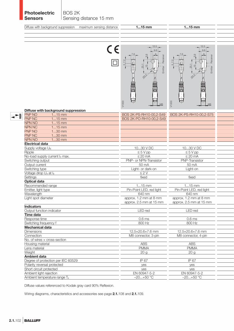
BOS 2KSensing distance 15 mm
Diffuse with background suppression maximum sensing distance
Diffuse with background suppressionPNP NO 1...15 mmPNP NC 1...15 mmNPN NO 1...15 mmNPN NC 1...15 mmPNP NO 1...30 mmPNP NC 1...30 mmNPN NO 1...30 mmElectrical dataSupply voltage UB
RippleNo-load supply current I0 max.Switching outputOutput currentSwitching typeVoltage drop Ud at IeSettingsOptical dataRecommended rangeEmitter, light typeWavelengthLight spot diameter
IndicatorsOutput function indicatorTime dataResponse timeSwitching frequency fMechanical dataDimensionsConnectionNo. of wires × cross-sectionHousing materialLens materialWeightAmbient dataDegree of protection per IEC 60529Polarity reversal protectedShort circuit protectedAmbient light rejectionAmbient temperature range Ta
1...15 mm
BOS 2K-PS-RH10-00,2-S49BOS 2K-PO-RH10-00,2-S49
10...30 V DC≤ 5 V pp≤ 20 mA
PNP- or NPN-Transistor50 mA
Light- or dark-on≤ 2 Vfixed
1...15 mmPin-Point LED, red light
640 nmapprox. 1.2 mm at 8 mmapprox. 2.5 mm at 15 mm
LED red
0.6 ms800 Hz
12.5×20.6×7.6 mmM8 connector, 3-pin
ABSPMMA20 g
IP 67yesyes
EN 60947-5-2–20...+50 °C
1...15 mm
BOS 2K-PS-RH10-00,2-S75
10...30 V DC≤ 5 V pp≤ 20 mA
PNP-Transistor50 mA
Light-on
fixed
1...15 mmPin-Point LED, red light
640 nmapprox. 1.2 mm at 8 mmapprox. 2.5 mm at 15 mm
LED red
0.6 ms800 Hz
12.5×20.6×7.6 mmM8 connector, 4-pin
ABSPMMA20 g
IP 67yesyes
EN 60947-5-2–20...+50 °C
Diffuse values referenced to Kodak gray card 90% Reflexion.
Wiring diagrams, characteristics and accessories see page 2.1.108 and 2.1.109.
� Rec
eive
rE
mitt
er
Rec
eive
rE
mitt
er
PhotoelectricSensors

BOS 2KSensing distance 15 mm,30 mm
2.1.103
2.1
2.3
1...15 mm
BOS 2K-PS-RH10-02
BOS 2K-NS-RH10-02BOS 2K-NO-RH10-02
10...30 V DC≤ 5 V pp≤ 20 mA
PNP- or NPN-Transistor50 mA
Light- or dark-on≤ 2 Vfixed
1...15 mmPin-Point LED, red light
640 nmapprox. 1.2 mm at 8 mmapprox. 2.5 mm at 15 mm
LED red
0.6 ms800 Hz
12.5×20.6×7.6 mm2 m cable, PVC
3×0.09 mm2
ABSPMMA18 g
IP 67yesyes
EN 60947-5-2–20...+50 °C
1...30 mm
BOS 2K-PS-RH11-00,2-S49
10...30 V DC≤ 5 V pp≤ 20 mA
PNP-Transistor50 mA
Light-on
fixed
1...30 mmPin-Point LED, red light
640 nmapprox. 1.0 mm at 15 mmapprox. 4.5 mm at 30 mm
LED red
0.6 ms800 Hz
12.5×20.6×7.6 mmM8 connector, 3-pin
ABSPMMA20 g
IP 67yesyes
EN 60947-5-2–20...+50 °C
1...30 mm
BOS 2K-PS-RH11-00,2-S75
10...30 V DC≤ 5 V pp≤ 20 mA
PNP-Transistor50 mA
Light-on
fixed
1...30 mmPin-Point LED, red light
640 nmapprox. 1.0 mm at 15 mmapprox. 4.5 mm at 30 mm
LED red
0.6 ms800 Hz
12.5×20.6×7.6 mmM8 connector, 4-pin
ABSPMMA20 g
IP 67yesyes
EN 60947-5-2–20...+50 °C
1...30 mm
BOS 2K-PS-RH11-02BOS 2K-PO-RH11-02BOS 2K-NS-RH11-02
10...30 V DC≤ 5 V pp≤ 20 mA
PNP- or NPN-Transistor50 mA
Light- or dark-on
fixed
1...30 mmPin-Point LED, red light
640 nmapprox. 1.0 mm at 15 mmapprox. 4.5 mm at 30 mm
LED red
0.6 ms800 Hz
12.5×20.6×7.6 mm2 m cable, PVC
3×0.09 mm2
ABSPMMA18 g
IP 67yesyes
EN 60947-5-2–20...+50 °C
www.balluff.com
5
Rec
eive
rE
mitt
er
Rec
eive
rE
mitt
er
Rec
eive
rE
mitt
er
Rec
eive
rE
mitt
er
PhotoelectricSensors
PhotoelectricSensorsAccessoriesPage 2.3.2 ...
Connectors ...Page 5.2 ...

2.1.104
BOS 2KSensing distance 55 mm
Diffuse maximum sensing distanceRetroreflective with polarizing filter maximum range
DiffusePNP NO 1...55 mmNPN NO 1...55 mmRetroreflectivePNP NO 45...800 mm Polarizing filterPNP NC 45...800 mm Polarizing filterNPN NO 45...800 mm Polarizing filterNPN NC 45...800 mm Polarizing filterElectrical dataSupply voltage UB
RippleNo-load supply current I0 max.Switching outputOutput currentSwitching typeVoltage drop Ud at IeSettingsOptical dataRecommended sensing distance/rangeEmitter, light typeWavelengthLight spot diameterIndicatorsOutput function indicatorTime dataResponse timeSwitching frequency fMechanical dataDimensionsConnectionNo. of wires × cross-sectionHousing materialLens materialWeightAmbient dataDegree of protection per IEC 60529Polarity reversal protectedShort circuit protectedAmbient light rejectionAmbient temperature range Ta
1...55 mm
BOS 2K-PS-RD10-00,2-S49
10...30 V DC≤ 5 V
≤ 20 mAPNP-Transistor
50 mALight-on
≤ 2 Vfixed
1...55 mmPin-Point LED, red light
640 nmapprox. 3.5 mm at 50 mm
LED red
0.6 ms800 Hz
12.5×20.6×7.6 mmM8 connector, 3-pin
ABSPMMA20 g
IP 67yesyes
EN 60947-5-2–20...+50 °C
1...55 mm
BOS 2K-PS-RD10-00,2-S75
10...30 V DC≤ 5 V
≤ 20 mAPNP-Transistor
50 mALight-on
≤ 2 Vfixed
1...55 mmPin-Point LED, red light
640 nmapprox. 3.5 mm at 50 mm
LED red
0.6 ms800 Hz
12.5×20.6×7.6 mmM8 connector, 4-pin
ABSPMMA20 g
IP 67yesyes
EN 60947-5-2–20...+50 °C
Diffuse values referenced to Kodak gray card 90% Reflexion.Retroreflective values referenced to R9 reflector.
Wiring diagrams, characteristics and accessories see page 2.1.108 and 2.1.109.
Rec
eive
rE
mitt
er
Rec
eive
rE
mitt
er
�
PhotoelectricSensors

BOS 2KSensing distance 55 mmRange 800 mm
2.1.105
2.1
2.3
1...55 mm
BOS 2K-PS-RD10-02BOS 2K-NS-RD10-02
10...30 V DC≤ 5 V
≤ 20 mAPNP- or NPN-Transistor
50 mALight-on
≤ 2 Vfixed
1...55 mmPin-Point LED, red light
640 nmapprox. 3.5 mm at 50 mm
LED red
0.6 ms800 Hz
12,5×20,6×7,6 mm2 m cable, PVC
3×0.09 mm2
ABSPMMA18 g
IP 67yesyes
EN 60947-5-2–20...+50 °C
45...800 mm
BOS 2K-PS-PR10-00,2-S49BOS 2K-PO-PR10-00,2-S49
10...30 V DC≤ 5 V
≤ 20 mAPNP-Transistor
50 mALight- or dark-on
≤ 2 Vfixed
25...500 mmPin-Point LED, red light
640 nmapprox. 10 mm at 100 mm
LED red
0.6 ms800 Hz
12.5×20.6×7.6 mmM8 connector, 3-pin
ABSPMMA20 g
IP 67yesyes
EN 60947-5-2–20...+50 °C
45...800 mm
BOS 2K-PS-PR10-00,2-S75
10...30 V DC≤ 5 V
≤ 20 mAPNP-Transistor
50 mADark-on
≤ 2 Vfixed
25...500 mmPin-Point LED, red light
640 nmapprox. 10 mm at 100 mm
LED red
0.6 ms800 Hz
12.5×20.6×7.6 mmM8 connector, 4-pin
ABSPMMA20 g
IP 67yesyes
EN 60947-5-2–20...+50 °C
45...800 mm
BOS 2K-PS-PR10-02BOS 2K-PO-PR10-02BOS 2K-NS-PR10-02BOS 2K-NO-PR10-02
10...30 V DC≤ 5 V
≤ 20 mAPNP- or NPN-Transistor
50 mALight- or dark-on
≤ 2 Vfixed
25...500 mmPin-Point LED, red light
640 nmapprox. 10 mm at 100 mm
LED red
0.6 ms800 Hz
12.5×20.6×7.6 mm2 m cable, PVC
3×0.09 mm2
ABSPMMA18 g
IP 67yesyes
EN 60947-5-2–20...+50 °C
www.balluff.com
5
Rec
eive
rE
mitt
er
Rec
eive
rE
mitt
er
Rec
eive
rE
mitt
er
Rec
eive
rE
mitt
er
PhotoelectricSensors
PhotoelectricSensorsAccessoriesPage 2.3.2 ...
Connectors ...Page 5.2 ...

2.1.106
BOS 2KRange 1,2 m
Through-beam maximum range
Through-beamPNP NO 1.2 m ReceiverPNP NC 1.2 m ReceiverNPN NO 1.2 m Receiver
1.2 m EmitterElectrical dataSupply voltage UB
RippleNo-load supply current I0 max.Switching outputOutput currentSwitching typeVoltage drop Ud at IeSettingsOptical dataRecommended rangeEmitter, light typeWavelengthLight spot diameterIndicatorsOutput function indicatorTime dataResponse timeSwitching frequency fMechanical dataDimensionsConnectionNo. of wires × cross-sectionHousing materialLens materialWeightAmbient dataDegree of protection per IEC 60529Polarity reversal protectedShort circuit protectedAmbient light rejectionAmbient temperature range Ta
Wiring diagrams, characteristics and accessories see page 2.1.108 and 2.1.109.
0...1,2 m
BOS 2K-PS-RE10-00,2-S49
10...30 V DC≤ 5 V
≤ 10 mAPNP-Transistor
50 mADark-on
≤ 2 Vfixed
0...1 mRed light640 nm
LED red
2.5 ms200 Hz
12.5×20.6×7.6 mmM8 connector, 3-pin
ABSPMMA20 g
IP 67yesyes
EN 60947-5-2–20...+50 °C
Rec
eive
r
0...1,2 m
BOS 2K-X-RS10-00,2-S49
10...30 V DC≤ 5 V
≤ 20 mA
0...1 mPin-Point LED, red light
640 nm
12.5×20.6×7.6 mmM8 connector, 3-pin
ABSPMMA20 g
IP 67yesyes
EN 60947-5-2–20...+50 °C
Em
itter
�
PhotoelectricSensors

BOS 2KRange 1,2 m
2.1.107
2.1
2.3
0...1,2 m
BOS 2K-PS-RE10-00,2-S75
10...30 V DC≤ 5 V
≤ 10 mAPNP-Transistor
50 mADark-on
≤ 2 Vfixed
0...1 mRed light640 nm
LED red
2.5 ms200 Hz
12.5×20.6×7.6 mmM8 connector, 4-pin
ABSPMMA20 g
IP 67yesyes
EN 60947-5-2–20...+50 °C
0...1,2 m
BOS 2K-PS-RE10-02BOS 2K-PO-RE10-02BOS 2K-NS-RE10-02
10...30 V DC≤ 5 V
≤ 10 mAPNP- or NPN-Transistor
50 mALight- or dark-on
≤ 2 Vfixed
0...1 mRed light640 nm
LED red
2.5 ms200 Hz
12.5×20.6×7.6 mm2 m cable, PVC
3×0.09 mm2
ABSPMMA18 g
IP 67yesyes
EN 60947-5-2–20...+50 °C
0...1,2 m
BOS 2K-X-RS10-00,2-S75
10...30 V DC≤ 5 V
≤ 20 mA
0...1 mPin-Point LED, red light
640 nm
12.5×20.6×7.6 mmM8 connector, 4-pin
ABSPMMA20 g
IP 67yesyes
EN 60947-5-2–20...+50 °C
0...1,2 m
BOS 2K-X-RS10-02
10...30 V DC≤ 5 V
≤ 20 mA
0...1 mPin-Point LED, red light
640 nm
12.5×20.6×7.6 mm2 m cable, PVC
3×0.09 mm2
ABSPMMA18 g
IP 67yesyes
EN 60947-5-2–20...+50 °C
www.balluff.com
5
Rec
eive
r
Em
itter
PhotoelectricSensors
PhotoelectricSensorsAccessoriesPage 2.3.2 ...
Connectors ...Page 5.2 ...
6.4
7.6
12.5
25.1
9
9.6
153.
9
Ø3.2
V10
05
6.4
7.6
12.5
25.1
9
9.6
153.
9
Ø3.2
V10
05
Em
itter
Rec
eive
r

2.1.108
BOS 2KFunction diagrams
Diffuse
Retroreflective
Through-beam
Function reserve
Function reserve
Light spot diameterDiffuse, 50 mm
Operating range
DiffuseLight spot diameterDiffuse withbackground suppression,15 mm
Sensing range on gray, 18 % remissionSensing range on white, 90 % remission
Sensing range on black, 6 % remission
Sensing range on gray, 18 % remissionSensing range on white, 90 % remission
Sensing range on black, 6 % remission
Sensing range on gray, 18 % remissionSensing range on white, 90 % remission
Sensing range on black, 6 % remission
Light spot diameterDiffuse withbackground suppression,30 mm
with background suppression15 mm
Diffusewith background suppression30 mm
PhotoelectricSensors
2.1
2.3
2.1.109
BOS 2KWiringAccessories
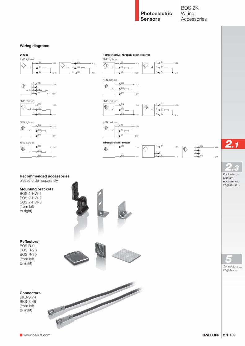
Wiring diagrams
Retroreflective, through-beam receiver
PNP light-on
Through-beam emitter
Diffuse
PNP light-on
NPN dark-on
NPN light-on
PNP dark-on
NPN light-on
NPN dark-on
Recommended accessoriesplease order separately
Mounting bracketsBOS 2-HW-1BOS 2-HW-2BOS 2-HW-3(from leftto right)
ReflectorsBOS R-9BOS R-26BOS R-30(from leftto right)
ConnectorsBKS-S 74BKS-S 48(from leftto right)
www.balluff.com
PNP dark-on
5
PhotoelectricSensors
PhotoelectricSensorsAccessoriesPage 2.3.2 ...
Connectors ...Page 5.2 ...

2.1.110
BOS 5K
Small sensors are easierto install and are even some-times the only alternative.The optical performanceof these miniature sensorsis astounding. Choosebetween integrated cableor an M8 connector forconnecting these sensors.
This series includes variousdiffuse sensors withbackground suppression,diffuse with narrow spotgeometry, energetic diffuse,retroreflective models withpolarizing filter and through-beam sensors.
Type
Diffuse with HGABOS 5K-PS-RH12-S75BOS 5K-PO-RH12-S75BOS 5K-PS-RH12-02BOS 5K-PO-RH12-02BOS 5K-NS-RH12-S75BOS 5K-NO-RH12-S75BOS 5K-NS-RH12-02BOS 5K-NO-RH12-02
OutputLighttype
Tast-/Reichweite
40...200 mm40...200 mm40...200 mm40...200 mm40...200 mm40...200 mm40...200 mm40...200 mm
Connec-tion
500 Hz500 Hz500 Hz500 Hz500 Hz500 Hz500 Hz500 Hz
Outputfunction
Page
2.1.1122.1.1122.1.1122.1.1122.1.1122.1.1122.1.1122.1.112
Specialfeatures
Red
ligh
t
Infra
red
M8
conn
ecto
r, 4-
pin
Cab
le
10...
30 V
DC
Pol
ariz
ing
filte
r
NP
N-T
rans
isto
r
PN
P-T
rans
isto
r
Ligh
t-on
Dar
k-on
UBSwitchingfrequency
The new BOS 5K seriesfeatures:
– A small, compact formfactor
– Emphasis on essential,basic functions
– Attractive price position inthe lower price segment
– Large range ofaccessories for increasedfunctionality
PhotoelectricSensors

BOS 5KProduct overview
2.1.111
2.1
2.3
Type
DiffuseBOS 5K-PS-ID10-S75BOS 5K-PO-ID10-S75BOS 5K-PS-ID10-02BOS 5K-PO-ID10-02BOS 5K-NS-ID10-S75BOS 5K-NO-ID10-S75BOS 5K-NS-ID10-02BOS 5K-NO-ID10-02
Diffuse small beamBOS 5K-PS-RD11-S75BOS 5K-PO-RD11-S75BOS 5K-PS-RD11-02BOS 5K-PO-RD11-02BOS 5K-NS-RD11-S75BOS 5K-NO-RD11-S75BOS 5K-NS-RD11-02BOS 5K-NO-RD11-02
RetroreflectiveBOS 5K-PS-RR10-S75BOS 5K-PO-RR10-S75BOS 5K-PO-RR10-S75-SBOS 5K-PS-RR10-02BOS 5K-PO-RR10-02BOS 5K-NS-RR10-S75BOS 5K-NO-RR10-S75BOS 5K-NO-RR10-S75-SBOS 5K-NS-RR10-02BOS 5K-NO-RR10-02
Through-beamBOS 5K-PS-IX10-S75BOS 5K-PO-IX10-S75BOS 5K-PO-IX10-S75-SBOS 5K-PS-IX10-02BOS 5K-PO-IX10-02BOS 5K-NS-IX10-S75BOS 5K-NO-IX10-S75BOS 5K-NO-IX10-S75-SBOS 5K-NS-IX10-02BOS 5K-NO-IX10-02
OutputLighttype
Tast-/Reichweite
0...900 mm0...900 mm0...900 mm0...900 mm0...900 mm0...900 mm0...900 mm0...900 mm
50...200 mm50...200 mm50...200 mm50...200 mm50...200 mm50...200 mm50...200 mm50...200 mm
0,1…4 m0,1…4 m0,1…4 m0,1…4 m0,1…4 m0,1…4 m0,1…4 m0,1…4 m0,1…4 m0,1…4 m
0…10 m0…10 m0…10 m0…10 m0…10 m0…10 m0…10 m0…10 m0…10 m0…10 m
Connec-tion
500 Hz500 Hz500 Hz500 Hz500 Hz500 Hz500 Hz500 Hz
500 Hz500 Hz500 Hz500 Hz500 Hz500 Hz500 Hz500 Hz
500 Hz500 Hz500 Hz500 Hz500 Hz500 Hz500 Hz500 Hz500 Hz500 Hz
500 Hz500 Hz500 Hz500 Hz500 Hz500 Hz500 Hz500 Hz500 Hz500 Hz
Outputfunction
Page
2.1.1132.1.1132.1.1132.1.1132.1.1132.1.1132.1.1132.1.113
2.1.1132.1.1132.1.1132.1.1132.1.1132.1.1132.1.1132.1.113
2.1.1142.1.1142.1.1142.1.1152.1.1152.1.1142.1.1142.1.1142.1.1152.1.115
2.1.1152.1.1152.1.1152.1.1152.1.1152.1.1152.1.1152.1.1152.1.1152.1.115
Specialfeatures
Red
ligh
t
Infra
red
M8
conn
ecto
r, 4-
pin
Cab
le
10...
30 V
DC
Pol
ariz
ing
filte
r
NP
N-T
rans
isto
r
PN
P-T
rans
isto
r
Ligh
t-on
Dar
k-on
UB
www.balluff.com
5
mini.swith potentiometer
PhotoelectricSensors
Switchingfrequency
PhotoelectricSensorsAccessoriesPage 2.3.2 ...
Connectors ...Page 5.2 ...

2.1.112
BOS 5KSensing distance 200 mm
Diffuse with background suppression Sensing distanceDiffuse Sensing distanceDiffuse small beam Sensing distance
Diffuse with HGAPNP, NO 50...200 mmNPN, NO 50...200 mmPNP, NC 50...200 mmNPN, NC 50...200 mmDiffusePNP, NO 900 mmNPN, NO 900 mmPNP, NC 900 mmNPN, NC 900 mmDiffuse small beamPNP, NO 50...200 mmNPN, NO 50...200 mmPNP, NC 50...200 mmNPN, NC 50...200 mmElectrical dataOperating voltage UB
RippleNo-load supply current I0 max.Switching outputOutput currentSwitching typeVoltage drop Ud at IeSettingsOptical dataEmitter, light typeWavelengthIndicatorsOutput function indicatorStability indicatorTime dataResponse timeSwitching frequency fMechanical dataDimensionsConnectionNo. of wires × cross-sectionHousing materialOptical surfaceWeightAmbient dataDegree of protection per IEC 60529Polarity reversal protectedShort circuit protectedAmbient temperature range Ta
Ambient light rejection
Diffuse values referenced to Kodak gray card 90% Reflexion.
Wiring diagrams, characteristics and accessories see page 2.1.116 and 2.1.117.
50...200 mm
BOS 5K-PS-RH12-S75BOS 5K-NS-RH12-S75BOS 5K-PO-RH12-S75BOS 5K-NO-RH12-S75
10...30 V DC≤ 2 V DC≤ 30 mA
PNP- or NPN-Transistor100 mA
Light- or dark-on≤ 1.2 V DC
Potentiometer 270°
LED, red light660 nm
LED yellowLED green
1 ms500 Hz
19.5×31.5×10.8 mmM8 connector, 4-pin
PC/PBTPC10 g
IP 67yesyes
–25...+55 °C5 kLux (artificial light)/10 kLux (sunlight)
50...200 mm
BOS 5K-PS-RH12-02BOS 5K-NS-RH12-02BOS 5K-PO-RH12-02BOS 5K-NO-RH12-02
10...30 V DC≤ 2 V DC≤ 30 mA
PNP- or NPN-Transistor100 mA
Light- or dark-on≤ 1.2 V DC
Potentiometer 270°
LED, red light660 nm
LED yellowLED green
1 ms500 Hz
19.5×31.5×10.8 mm2 m cable, PVC
3×0.2 mm²PC/PBT
PC50 g
IP 67yesyes
–25...+55 °C5 kLux (artificial light)/10 kLux (sunlight)
Rec
eive
rE
mitt
er
LEDPoti
LED
Rec
eive
rE
mitt
er
LEDPoti
LED
PhotoelectricSensors

BOS 5KSensing distance 200 mm,900 mm
2.1.113
2.1
2.3
Connector orientation
mini.swith potentiometer
www.balluff.com
0...900 mm
BOS 5K-PS-ID10-02BOS 5K-NS-ID10-02BOS 5K-PO-ID10-02BOS 5K-NO-ID10-02
10...30 V DC≤ 2 V DC≤ 30 mA
PNP- or NPN-Transistor100 mA
Light- or dark-on≤ 1.2 V DC
Potentiometer 270°
LED, infrared880 nm
LED yellowLED green
1 ms500 Hz
19.5×31.5×10.8 mm2 m cable, PVC
3×0.2 mm²PC/PBT
PC50 g
IP 67yesyes
–25...+55 °C5 kLux (artificial light)/10 kLux (sunlight)
0...900 mm
BOS 5K-PS-ID10-S75BOS 5K-NS-ID10-S75BOS 5K-PO-ID10-S75BOS 5K-NO-ID10-S75
10...30 V DC≤ 2 V DC≤ 30 mA
PNP- or NPN-Transistor100 mA
Light- or dark-on≤ 1.2 V DC
Potentiometer 270°
LED, infrared880 nm
LED yellowLED green
1 ms500 Hz
19.5×31.5×10.8 mmM8 connector, 4-pin
PC/PBTPC
10 g
IP 67yesyes
–25...+55 °C5 kLux (artificial light)/10 kLux (sunlight)
50...200 mm
BOS 5K-PS-RD11-S75BOS 5K-NS-RD11-S75BOS 5K-PO-RD11-S75BOS 5K-NO-RD11-S75
10...30 V DC≤ 2 V DC≤ 30 mA
PNP- or NPN-Transistor100 mA
Light- or dark-on≤ 1.2 V DC
Potentiometer 270°
LED, red light660 nm
LED yellowLED green
1 ms500 Hz
19.5×31.5×10.8 mmM8 connector, 4-pin
PC/PBTPC
10 g
IP 67yesyes
–25...+55 °C5 kLux (artificial light)/10 kLux (sunlight)
50...200 mm
BOS 5K-PS-RD11-02BOS 5K-NS-RD11-02BOS 5K-PO-RD11-02BOS 5K-NO-RD11-02
10...30 V DC≤ 2 V DC≤ 30 mA
PNP- or NPN-Transistor100 mA
Light- or dark-on≤ 1.2 V DC
Potentiometer 270°
LED, red light660 nm
LED yellowLED green
1 ms500 Hz
19.5×31.5×10.8 mm2 m cable, PVC
3×0.2 mm²PC/PBT
PC50 g
IP 67yesyes
–25...+55 °C5 kLux (artificial light)/10 kLux (sunlight)
5
Rec
eive
rE
mitt
er
LEDPoti
LED
Rec
eive
rE
mitt
er
LEDPoti
LEDR
ecei
ver
Em
itter
LEDPoti
LED
Rec
eive
rE
mitt
er
LEDPoti
LED
PhotoelectricSensors
PhotoelectricSensorsAccessoriesPage 2.3.2 ...
Connectors ...Page 5.2 ...

2.1.114
BOS 5KRange 4 m
Retroreflective RangeThrough-beam Range
RetroreflectivePNP, NO 0,1...4 m Polarizing filterNPN, NO 0,1...4 m Polarizing filterPNP, NC 0,1...4 m Polarizing filterNPN, NC 0,1...4 m Polarizing filterPNP, NC 0,1...4 m Polarizing filter Special output configurationNPN, NC 0,1...4 m Polarizing filter Special output configurationThrough-beamPNP, NO 10 m Emitter + ReceiverNPN, NO 10 m Emitter + ReceiverPNP, NC 10 m Emitter + ReceiverNPN, NC 10 m Emitter + ReceiverPNP, NC 10 m Emitter + Receiver Special output configurationNPN, NC 10 m Emitter + Receiver Special output configurationElectrical dataOperating voltage UB
RippleNo-load supply current I0 max.Switching outputOutput currentSwitching typeVoltage drop Ud at IeSettingsOptical dataEmitter, light typeWavelengthIndicatorsPower-on indicatorOutput function indicatorStability indicatorTime dataResponse timeSwitching frequency fMechanical dataDimensionsConnectionNo. of wires × cross-sectionHousing materialOptical surfaceWeightAmbient dataDegree of protection per IEC 60529Polarity reversal protectedShort circuit protectedAmbient temperature range Ta
Ambient light rejectionRetroreflective values referenced to R1 reflector.
Wiring diagrams, characteristics and accessories see page 2.1.116 and 2.1.117.
0,1...4 m
BOS 5K-PS-RR10-S75BOS 5K-NS-RR10-S75BOS 5K-PO-RR10-S75BOS 5K-NO-RR10-S75BOS 5K-PO-RR10-S75-SBOS 5K-NO-RR10-S75-S
10...30 V DC≤ 2 V DC≤ 30 mA
PNP- or NPN-Transistor100 mA
Light- or dark-on≤ 1.2 V DC
Potentiometer 270°
LED, red light660 nm
LED yellowLED green
1 ms500 Hz
19.5×31.5×10.8 mmM8 connector, 4-pin
PC/PBTPMMA10 g
IP 67yesyes
–25...+55 °C5 kLux (artificial light)/10 kLux (sunlight)
Rec
eive
rE
mitt
er
LEDPoti
LED
PhotoelectricSensors

BOS 5KRange 4 m, 10 m
0,1...4 m
BOS 5K-PS-RR10-02BOS 5K-NS-RR10-02BOS 5K-PO-RR10-02BOS 5K-NO-RR10-02
10...30 V DC≤ 2 V DC≤ 30 mA
PNP- or NPN-Transistor100 mA
Light- or dark-on≤ 1.2 V DC
Potentiometer 270°
LED, red light660 nm
LED yellowLED green
1 ms500 Hz
19.5×31.5×10.8 mm2 m cable, PVC
3×0.2 mm²PC/PBTPMMA50 g
IP 67yesyes
–25...+55 °C5 kLux (artificial light)/10 kLux (sunlight)
0...10 m
BOS 5K-PS-IX10-S75BOS 5K-NS-IX10-S75BOS 5K-PO-IX10-S75BOS 5K-NO-IX10-S75BOS 5K-PO-IX10-S75-SBOS 5K-NO-IX10-S75-S
10...30 V DC≤ 2 V DC
≤ 20 mA (Receiver), ≤ 15 mA (Emitter)PNP- or NPN-Transistor
100 mALight- or dark-on
≤ 1.2 V DCPotentiometer 270°
LED, infrared880 nm
LED green (emitter)LED yellow (receiver)LED green (receiver)
≤ 1 ms500 Hz
19.5×31.5×10.8 mmM8 connector, 4-pin
PC/PBTPC
10 g each
IP 67yesyes
–25...+55 °C5 kLux (artificial light)/10 kLux (sunlight)
0...10 m
BOS 5K-PS-IX10-02BOS 5K-NS-IX10-02BOS 5K-PO-IX10-02BOS 5K-NO-IX10-02
10...30 V DC≤ 2 V DC
≤ 20 mA (Receiver), ≤ 15 mA (Emitter)PNP- or NPN-Transistor
100 mALight- or dark-on
≤ 1.2 V DCPotentiometer 270°
LED, infrared880 nm
LED green (emitter)LED yellow (receiver)LED green (receiver)
≤ 1 ms500 Hz
19.5×31.5×10.8 mm2 m cable, PVC
3(2)×0,2 mm² (emitter)PC/PBT
PC50 g each
IP 67yesyes
–25...+55 °C5 kLux (artificial light)/10 kLux (sunlight)
2.1.115
2.1
2.3
Em
itter
/R
ecei
ver
Sender ReceiverLEDPoti
LED
LED
Connector orientation
mini.swith potentiometer
www.balluff.com
5
Rec
eive
rE
mitt
er
LEDPoti
LED
Emitter
Em
itter
/R
ecei
ver
ReceiverLEDPoti
LED
LEDEmitter
PhotoelectricSensors
PhotoelectricSensorsAccessoriesPage 2.3.2 ...
Connectors ...Page 5.2 ...

2.1.116
BOS 5KFunction diagrams
Diffuse BOS 5K-_ _-ID10-_ _Receiving characteristics
Diffuse small beam BOS 5K-_ _-RD11-_ _Receiving characteristics
Reflexionslichtschranke BOS 5K-_ _-RR10-_ _Receiving characteristics
Einweglichtschranke BOS 5K-_ _-IX10-_ _Receiving characteristics
Diffuse with background suppression BOS 5K-_ _-RH12-_ _Light spot diameter
Sensing distance (mm) Sensing distance (mm) Sensing distance (mm)
Sensing distance (mm) Sensing distance (mm) Object size (mm)
Sensing distance (mm) Sensing distance (mm) Object size (mm)
Range (m) Range (m) Range (m)
Range (m) Range (m) Range (m)
Characteristic response curve
Characteristic response curve
Characteristic response curve
Characteristic response curve
Object size vs. Sensing distance
Object size vs. Sensing distance
Angle offset
Angle offset
Func
tion
rese
rve
Func
tion
rese
rve
Func
tion
rese
rve
Func
tion
rese
rve
Late
ral a
ppro
ach
(mm
)La
tera
l app
roac
h (m
m)
Late
ral a
ppro
ach
(mm
)La
tera
l app
roac
h (m
m)
Sen
sing
dis
tanc
e (m
m)
Sen
sing
dis
tanc
e (m
m)
Ang
le r
efle
ctor
Ang
le r
ecei
ver
Characteristic response curve (HGA 100 mm) Sensing distance vs. hysteresis
Ligh
t spo
t dia
met
er (m
m)
Late
ral a
ppro
ach
(mm
)
Hys
tere
sis
Kodak 6 %
Kodak 18 %
Kodak 90 %
Kodak 6 %
Kodak 90 %
Object size 200×200 mm
Object size 200×200 mm
Object size 100×100 mm
Kodak 90 %
Kodak 90 %
Kodak 90 %Kodak 90 %
BOS-R9/R25
BOS-R26
BOS-R30
BOS-R27/28/29
BOS-R9/R25
BOS-R26
BOS-R30
BOS-R27/28/29
BOS-R9/R25
BOS-R26
BOS-R27/28/29
BOS-R30
PhotoelectricSensors

Recommended accessoriesplease order separately
Mounting bracketsBOS 5-HW-1BOS 5-HW-2BOS 5-HW-3(from left to right)
Reflectors,Reflector mounting bracketBOS R-1BOS R-25BOS 5-HW-4BOS R-26BOS 5-HW-5BOS R-9BOS 5-HW-6BOS R-27BOS R-28BOS R-29BOS R-30(from left to right)
Slit apertures, verticalBOS 5-BL-1BOS 5-BL-2BOS 5-BL-3
Slit apertures, horizontalBOS 5-BL-4BOS 5-BL-5BOS 5-BL-6
Round aperturesBOS 5-BL-7BOS 5-BL-8BOS 5-BL-9(from left to right)
2.1.117
BOS 5KWiringAccessories
2.1
2.3
ConnectorBKS-S 74/BKS-S 75
mini.swith potentiometer
www.balluff.com
5
BOS 5K-PO-...
BOS 5K-NO-...
BOS 5K-PO-...S75-S BOS 5K-NO-...S75-S
Wiring diagrams
BOS 5K-PS-...
BOS 5K-NS-...
Through-beam emitter
PhotoelectricSensors
PhotoelectricSensorsAccessoriesPage 2.3.2 ...
Connectors ...Page 5.2 ...

BOS 6KProduct overview
2.1.118
Its high performancespecs allow the BOS 6K tobe used virtually anywhere.These sensors areparticularly useful for tightmounting spaces. The smallsize allows better integrationinto the machine.Red light and backgroundsuppression make thesensor extremely user-friendly.
Features
– Teach-in button pluscontrol line
– Dynamic teach-in possible(i. e., without stopping themachine)
– Multi-function displayvisible from any direction
– Key disabling– Versions with 3- or
4-pin M8 connector orwith 2 m cable
– Solid construction withIP 67 rating
– Red light and laserversions
In addition, several laserversions are available forabsolute small partsdetection.Automatic calibration usingthe control lines meansthe sensor can be installedat virtually inaccessiblelocations. Dynamic teach-inmeans less and lessattention needs to be paidto the sensors.
Applications
– Packaging machinery– Handling and assembly– Specialty machines– Printing and
paper machines
Type
Diffuse with HGABOS 6K-PU-1HA-S75-CBOS 6K-NU-1HA-S75-CBOS 6K-PU-1HA-S49-CBOS 6K-PU-1HA-C-02BOS 6K-NU-1HA-C-02
BOS 6K-PU-1LHA-S75-CBOS 6K-NU-1LHA-S75-CBOS 6K-PU-1LHA-C-02BOS 6K-NU-1LHA-C-02
BOS 6K-PU-1LHA-SA1-S75-CBOS 6K-NU-1LHA-SA1-S75-CBOS 6K-PU-1LHA-SA1-C-02BOS 6K-NU-1LHA-SA1-C-02
OutputLighttype
Sensing/Range
25...100 mm25...100 mm25...100 mm25...100 mm25...100 mm
20...60 mm20...60 mm20...60 mm20...60 mm
30...110 mm30...110 mm30...110 mm30...110 mm
Connection
1 kHz1 kHz1 kHz1 kHz1 kHz
1 kHz1 kHz1 kHz1 kHz
1 kHz1 kHz1 kHz1 kHz
Outputfunction
Page
2.1.1202.1.1202.1.1202.1.1212.1.121
2.1.1262.1.1262.1.1262.1.126
2.1.1272.1.1272.1.1272.1.127
Specialfeatures
Red
ligh
t
Lase
r
M8
conn
ecto
r, 4-
pin
Cab
le
10...
30 V
DC
Pol
ariz
ing
filte
r
NP
N-T
rans
isto
r
PN
P-T
rans
isto
r
Ligh
t-on
Dar
k-on
UBSwitchingfrequency
M8
conn
ecto
r, 3-
pin
PhotoelectricSensors

BOS 6KProduct overview
2.1
2.3
2.1.119
Type
DiffuseBOS 6K-PU-1OC-S75-CBOS 6K-NU-1OC-S75-CBOS 6K-PU-1OC-S49-CBOS 6K-PU-1OC-C-02BOS 6K-NU-1OC-C-02
RetroreflectiveBOS 6K-PU-1TA-S75-CBOS 6K-NU-1TA-S75-CBOS 6K-PU-1TA-C-02BOS 6K-NU-1TA-C-02
BOS 6K-PU-1QA-S75-CBOS 6K-NU-1QA-S75-CBOS 6K-PU-1QA-S49-CBOS 6K-PU-1QA-C-02BOS 6K-NU-1QA-C-02
BOS 6K-PU-1LQA-S75-CBOS 6K-NU-1LQA-S75-CBOS 6K-PU-1LQA-C-02BOS 6K-NU-1LQA-C-02
BOS 6K-PU-1QC-S75-CBOS 6K-NU-1QC-S75-CBOS 6K-PU-1QC-S49-CBOS 6K-PU-1QC-C-02BOS 6K-NU-1QC-C-02
Through-beamBLE 6K-PU-1E-S75-CBLE 6K-NU-1E-S75-CBLE 6K-PU-1E-S49-CBLE 6K-PU-1E-C-02BLE 6K-NU-1E-C-02
BLS 6K-XX-1E-S75-CBLS 6K-XX-1E-S49-CBLS 6K-XX-1E-C-02
OutputLighttype
Sensing/Range
20...300 mm20...300 mm20...300 mm20...300 mm20...300 mm
0...500 mm0...500 mm0...500 mm0...500 mm
50...700 mm50...700 mm50...700 mm50...700 mm50...700 mm
0,05...1,5 m0,05...1,5 m0,05...1,5 m0,05...1,5 m
0,05...3 m0,05...3 m0,05...3 m0,05...3 m0,05...3 m
0...6,5 m0...6,5 m0...6,5 m0...6,5 m0...6,5 m
0...6,5 m0...6,5 m0...6,5 m
Connection
1 kHz1 kHz1 kHz1 kHz1 kHz
1 kHz1 kHz1 kHz1 kHz
1 kHz1 kHz1 kHz1 kHz1 kHz
4 kHz4 kHz4 kHz4 kHz
1 kHz1 kHz1 kHz1 kHz1 kHz
500 Hz500 Hz500 Hz500 Hz500 Hz
Outputfunction
Page
2.1.1212.1.1212.1.1212.1.1212.1.121
2.1.1222.1.1222.1.1222.1.122
2.1.1232.1.1232.1.1232.1.1232.1.123
2.1.1272.1.1272.1.1272.1.127
2.1.1242.1.1242.1.1242.1.1252.1.125
2.1.1252.1.1252.1.1252.1.1252.1.125
2.1.1252.1.1252.1.125
Specialfeatures
Red
ligh
t
Lase
r
M8
conn
ecto
r, 4-
pin
Cab
le
10...
30 V
DC
Pol
ariz
ing
filte
r
NP
N-T
rans
isto
r
PN
P-T
rans
isto
r
Ligh
t-on
Dar
k-on
UBSwitchingfrequency
M8
conn
ecto
r, 3-
pin
mini.swith teach-in
www.balluff.com
Gla
ss s
ensi
ng
5
PhotoelectricSensors
PhotoelectricSensorsAccessoriesPage 2.3.2 ...
Connectors ...Page 5.2 ...

BOS 6KSensing distance 100 mm
Diffuse with background suppression maximum sensing distanceDiffuse maximum sensing distance
1)
DiffusePNP 25...100 mm HGANPN 25...100 mm HGAPNP 20...300 mmNPN 20...300 mmElectrical dataSupply voltage UB
No-load supply current I0 max.Switching outputOutput currentSwitching typeVoltage drop Ud at IeSettingsOptical dataRecommended sensing distanceEmitter, light typeWavelengthLight spot diameterDistance hysteresis (18 %/18 %)Gray value shift (90 %/18 %)IndicatorsSwitching state indicatorStability indicatorTime dataResponse timeSwitching frequency fMechanical dataDimensionsConnectionNo. of wires × cross-sectionHousing materialOptical surfaceWeightAmbient dataDegree of protection per IEC 60529Polarity reversal protectedShort circuit protectedAmbient temperature range Ta
Ambient light rejection
25...100 mm
BOS 6K-PU-1HA-S75-CBOS 6K-NU-1HA-S75-C
10...30 V DC≤ 35 mA
PNP- or NPN-Transistor100 mA
Light-/dark-on (selectable)≤ 2.4 Vteach-in
25...100 mmLED, red light
660 nmca. 5×5 mm at 60 mm
≤ 5 %≤ 10 %
LED yellowLED green
0.5 ms1 kHz
21×32×12 mmM8 connector, 4-pin
impact-resistant ABSPMMA40 g
IP 67yesyes
–20...+60 °C5 kLux
2.1.120
25...100 mm
BOS 6K-PU-1HA-S49-C
10...30 V DC≤ 35 mA
PNP-Transistor100 mA
Light-/dark-on (selectable)≤ 2.4 Vteach-in
25...100 mmLED, red light
660 nmca. 5×5 mm at 60 mm
≤ 5 %≤ 10 %
LED yellowLED green
0.5 ms1 kHz
21×32×12 mmM8 connector, 3-pin
impact-resistant ABSPMMA40 g
IP 67yesyes
–20...+60 °C5 kLux
www.balluff.com
Diffuse values referenced to Kodak gray card 90% Reflexion.
Wiring diagrams, characteristics and accessories see page 2.1.128 and 2.1.129.
1) Uimp = 500 V
Teach-inTeach-in
�
PhotoelectricSensors

BOS 6KSensing distance 100 mm,300 mm
25...100 mm
BOS 6K-PU-1HA-C-02BOS 6K-NU-1HA-C-02
10...30 V DC≤ 35 mA
PNP- or NPN-Transistor100 mA
Light-/dark-on (selectable)≤ 2.4 Vteach-in
25...100 mmLED, red light
660 nmca. 5×5 mm at 60 mm
≤ 5 %≤ 10 %
LED yellowLED green
0.5 ms1 kHz
21×32×12 mm2 m cable, PVC
4×0.14 mm²impact-resistant ABS
PMMA120 g
IP 67yesyes
–20...+60 °C5 kLux
2.1.121
2.1
2.3
mini.swith teach-in
20...300 mm
BOS 6K-PU-1OC-S75-CBOS 6K-NU-1OC-S75-C
10...30 V DC≤ 35 mA
PNP- or NPN-Transistor100 mA
Light-/dark-on (selectable)≤ 2.4 Vteach-in
20...300 mmLED, red light
660 nmca. 12×12 mm at 160 mm
≤ 10 %
LED yellowLED green
0.5 ms1 kHz
21×32×12 mmM8 connector, 4-pin
impact-resistant ABSPMMA40 g
IP 67yesyes
–20...+60 °C5 kLux
20...300 mm
BOS 6K-PU-1OC-C-02BOS 6K-NU-1OC-C-02
10...30 V DC≤ 35 mA
PNP- or NPN-Transistor100 mA
Light-/dark-on (selectable)≤ 2.4 Vteach-in
20...300 mmLED, red light
660 nmca. 12×12 mm at 160 mm
≤ 10 %
LED yellowLED green
0.5 ms1 kHz
21×32×12 mm2 m cable, PVC
4×0.14 mm²impact-resistant ABS
PMMA120 g
IP 67yesyes
–20...+60 °C5 kLux
20...300 mm
BOS 6K-PU-1OC-S49-C
10...30 V DC≤ 35 mA
PNP-Transistor100 mA
Light-/dark-on (selectable)≤ 2.4 Vteach-in
20...300 mmLED, red light
660 nmca. 12×12 mm at 160 mm
≤ 10 %
LED yellowLED green
0.5 ms1 kHz
21×32×12 mmM8 connector, 3-pin
impact-resistant ABSPMMA40 g
IP 67yesyes
–20...+60 °C5 kLux
Connector orientation
Teach-in Teach-inTeach-in Teach-in
5
PhotoelectricSensors
PhotoelectricSensorsAccessoriesPage 2.3.2 ...
Connectors ...Page 5.2 ...
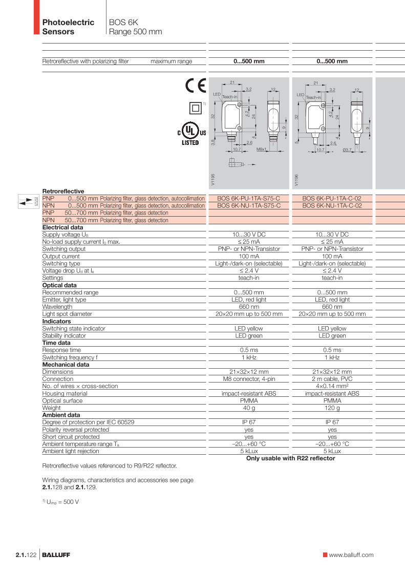
0...500 mm
BOS 6K-PU-1TA-S75-CBOS 6K-NU-1TA-S75-C
10...30 V DC≤ 25 mA
PNP- or NPN-Transistor100 mA
Light-/dark-on (selectable)≤ 2.4 Vteach-in
0...500 mmLED, red light
660 nm20×20 mm up to 500 mm
LED yellowLED green
0.5 ms1 kHz
21×32×12 mmM8 connector, 4-pin
impact-resistant ABSPMMA40 g
IP 67yesyes
–20...+60 °C5 kLux
BOS 6KRange 500 mm
Retroreflective with polarizing filter maximum range
1)
RetroreflectivePNP 0...500 mm Polarizing filter, glass detection, autocollimationNPN 0...500 mm Polarizing filter, glass detection, autocollimationPNP 50...700 mm Polarizing filter, glass detectionNPN 50...700 mm Polarizing filter, glass detectionElectrical dataSupply voltage UB
No-load supply current I0 max.Switching outputOutput currentSwitching typeVoltage drop Ud at IeSettingsOptical dataRecommended rangeEmitter, light typeWavelengthLight spot diameterIndicatorsSwitching state indicatorStability indicatorTime dataResponse timeSwitching frequency fMechanical dataDimensionsConnectionNo. of wires × cross-sectionHousing materialOptical surfaceWeightAmbient dataDegree of protection per IEC 60529Polarity reversal protectedShort circuit protectedAmbient temperature range Ta
Ambient light rejection
0...500 mm
BOS 6K-PU-1TA-C-02BOS 6K-NU-1TA-C-02
10...30 V DC≤ 25 mA
PNP- or NPN-Transistor100 mA
Light-/dark-on (selectable)≤ 2.4 Vteach-in
0...500 mmLED, red light
660 nm20×20 mm up to 500 mm
LED yellowLED green
0.5 ms1 kHz
21×32×12 mm2 m cable, PVC
4×0.14 mm²impact-resistant ABS
PMMA120 g
IP 67yesyes
–20...+60 °C5 kLux
2.1.122 www.balluff.com
Retroreflective values referenced to R9/R22 reflector.
Wiring diagrams, characteristics and accessories see page2.1.128 and 2.1.129.
1) Uimp = 500 V
Only usable with R22 reflector
�
PhotoelectricSensors

BOS 6KRange 700 mm
2.1.123
2.1
2.3
mini.swith teach-in
50...700 mm
BOS 6K-PU-1QA-S75-CBOS 6K-NU-1QA-S75-C
10...30 V DC≤ 35 mA
PNP- or NPN-Transistor100 mA
Light-/dark-on (selectable)≤ 2.4 Vteach-in
0...500 mmLED, red light
660 nm20×20 mm up to 500 mm
LED yellowLED green
0.5 ms1 kHz
21×32×12 mmM8 connector, 4-pin
impact-resistant ABSPMMA40 g
IP 67yesyes
–20...+60 °C5 kLux
50...700 mm
BOS 6K-PU-1QA-C-02BOS 6K-NU-1QA-C-02
10...30 V DC≤ 35 mA
PNP- or NPN-Transistor100 mA
Light-/dark-on (selectable)≤ 2.4 Vteach-in
0...500 mmLED, red light
660 nm20×20 mm up to 500 mm
LED yellowLED green
0.5 ms1 kHz
21×32×12 mm2 m cable, PVC
4×0.14 mm²impact-resistant ABS
PMMA120 g
IP 67yesyes
–20...+60 °C5 kLux
50...700 mm
BOS 6K-PU-1QA-S49-C
10...30 V DC≤ 35 mA
PNP-Transistor100 mA
Light-/dark-on (selectable)≤ 2.4 Vteach-in
0...500 mmLED, red light
660 nm20×20 mm up to 500 mm
LED yellowLED green
0.5 ms1 kHz
21×32×12 mmM8 connector, 3-pin
impact-resistant ABSPMMA40 g
IP 67yesyes
–20...+60 °C5 kLux
Connector orientation
Teach-in Teach-in Teach-in
5
PhotoelectricSensors
PhotoelectricSensorsAccessoriesPage 2.3.2 ...
Connectors ...Page 5.2 ...
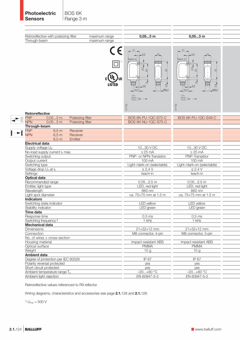
BOS 6KRange 3 m
Retroreflective with polarizing filter maximum rangeThrough-beam maximum range
1)
RetroreflectivePNP 0,05...3 m Polarizing filterNPN 0,05...3 m Polarizing filterThrough-beamPNP 6,5 m ReceiverNPN 6,5 m Receiver
6,5 m EmitterElectrical dataSupply voltage UB
No-load supply current I0 max.Switching outputOutput currentSwitching typeVoltage drop Ud at IeSettingsOptical dataRecommended rangeEmitter, light typeWavelengthLight spot diameterIndicatorsSwitching state indicatorStability indicatorTime dataResponse timeSwitching frequency fMechanical dataDimensionsConnectionNo. of wires × cross-sectionHousing materialOptical surfaceWeightAmbient dataDegree of protection per IEC 60529Polarity reversal protectedShort circuit protectedAmbient temperature range Ta
Ambient light rejection
0,05...3 m
BOS 6K-PU-1QC-S75-CBOS 6K-NU-1QC-S75-C
10...30 V DC≤ 25 mA
PNP- or NPN-Transistor100 mA
Light-/dark-on (selectable)≤ 2.4 Vteach-in
0.05...2.5 mLED, red light
660 nmca. 75×75 mm at 1.5 m
LED yellowLED green
0.5 ms1 kHz
21×32×12 mmM8 connector, 4-pin
impact-resistant ABSPMMA10 g
IP 67yesyes
–20...+60 °CEN 60947-5-2
2.1.124
0,05...3 m
BOS 6K-PU-1QC-S49-C
10...30 V DC≤ 25 mA
PNP-Transistor100 mA
Light-/dark-on (selectable)≤ 2.4 Vteach-in
0.05...2.5 mLED, red light
660 nmca. 75×75 mm at 1.5 m
LED yellowLED green
0.5 ms1 kHz
21×32×12 mmM8 connector, 3-pin
impact-resistant ABSPMMA10 g
IP 67yesyes
–20...+60 °CEN 60947-5-2
www.balluff.com
Retroreflective values referenced to R9 reflector.
Wiring diagrams, characteristics and accessories see page 2.1.128 and 2.1.129.
1) Uimp = 500 V
Teach-inTeach-in
�
PhotoelectricSensors

0...6,5 m
BLE 6K-PU-1E-S75-CBLE 6K-NU-1E-S75-CBLS 6K-XX-1E-S75-C
10...30 V DC≤ 25 mA
PNP- or NPN-Transistor100 mA
Light-/dark-on (selectable)≤ 2.4 Vteach-in
0...6 mLED, red light
660 nm
LED yellowLED green
1 ms500 Hz
21×32×12 mmM8 connector, 4-pin
impact-resistant ABSPMMA10 g
IP 67yesyes
–20...+60 °CEN 60947-5-2
BOS 6KRange 3 m, 6,5 m
0,05...3 m
BOS 6K-PU-1QC-C-02BOS 6K-NU-1QC-C-02
10...30 V DC≤ 25 mA
PNP- or NPN-Transistor100 mA
Light-/dark-on (selectable)≤ 2.4 Vteach-in
0.05...2.5 mLED, red light
660 nmca. 75×75 mm at 1.5 m
LED yellowLED green
0.5 ms1 kHz
21×32×12 mm2 m cable, PVC
4×0.14 mm²impact-resistant ABS
PMMA40 g
IP 67yesyes
–20...+60 °CEN 60947-5-2
2.1.125
2.1
2.3
mini.swith teach-in
0...6,5 m
BLE 6K-PU-1E-C-02BLE 6K-NU-1E-C-02BLS 6K-XX-1E-C-02
10...30 V DC≤ 25 mA
PNP- or NPN-Transistor100 mA
Light-/dark-on (selectable)≤ 2.4 Vteach-in
0...6 mLED, red light
660 nm
LED yellowLED green
1 ms500 Hz
21×32×12 mm2 m cable, PVC
4×0.14 mm²impact-resistant ABS
PMMA40 g
IP 67yesyes
–20...+60 °CEN 60947-5-2
0...6,5 m
BLE 6K-PU-1E-S49-C
BLS 6K-XX-1E-S49-C
10...30 V DC≤ 25 mA
PNP-Transistor100 mA
Light-/dark-on (selectable)≤ 2.4 Vteach-in
0...6 mLED, red light
660 nm
LED yellowLED green
1 ms500 Hz
21×32×12 mmM8 connector, 3-pin
impact-resistant ABSPMMA10 g
IP 67yesyes
–20...+60 °CEN 60947-5-2
Connector orientation
Teach-in Teach-inTeach-in Teach-in
5
PhotoelectricSensors
PhotoelectricSensorsAccessoriesPage 2.3.2 ...
Connectors ...Page 5.2 ...

20...60 mm
BOS 6K-PU-1LHA-C-02BOS 6K-NU-1LHA-C-02
10...30 V DC≤ 25 mA
PNP- or NPN-Transistor100 mA
Light-/dark-on (selectable)≤ 2.4 Vteach-in
20...60 mmLaser, red light
650 nm1
0.5 mm at focus (35 mm)≤ 2 % up to focal point, ≤ 6 % up to end
≤ 7 %
LED yellowLED green
0.5 ms1 kHz
21×32×12 mm2 m cable, PVC
4×0.14 mm²impact-resistant ABS
PMMA40 g
IP 67yesyes
–20...+60 °CEN 60947-5-2
Diffuse values referenced to Kodak gray card 18% Reflexion.Retroreflective values referenced to R22 reflector.
Wiring diagrams, characteristics and accessories see page 2.1.128 and 2.1.129.
1) Uimp = 500 V
2.1.126
BOS 6K LaserSensing distance 60 mm
Diffuse with background suppression maximum sensing distance
Retroreflective with polarizing filter maximum range
1)
DiffusePNP 20...60 mm HGANPN 20...60 mm HGAPNP 30...110 mm HGANPN 30...110 mm HGAReflexionslichtschrankePNP 0.05...1.5 m Polarizing filterNPN 0.05...1.5 m Polarizing filterElectrical dataSupply voltage UB
No-load supply current I0 max.Switching outputOutput currentSwitching typeVoltage drop Ud at IeSettingsOptical dataRecommended sensing distance/rangeEmitter, light typeWavelengthLaser classLight spot diameterDistance hysteresis (18 %/18 %)Gray value shift (90 %/18 %)IndicatorsSwitching state indicatorStability indicatorTime dataResponse timeSwitching frequency fMechanical dataDimensionsConnectionNo. of wires × cross-sectionHousing materialOptical surfaceWeightAmbient dataDegree of protection per IEC 60529Polarity reversal protectedShort circuit protectedAmbient temperature range Ta
Ambient light limit
20...60 mm
BOS 6K-PU-1LHA-S75-CBOS 6K-NU-1LHA-S75-C
10...30 V DC≤ 25 mA
PNP- or NPN-Transistor100 mA
Light-/dark-on (selectable)≤ 2.4 Vteach-in
20...60 mmLaser, red light
650 nm1
0.5 mm at focus (35 mm)≤ 2 % up to focal point, ≤ 6 % up to end
≤ 7 %
LED yellowLED green
0.5 ms1 kHz
21×32×12 mmM8 connector, 4-pin
impact-resistant ABSPMMA10 g
IP 67yesyes
–20...+60 °CEN 60947-5-2
Teach-inTeach-in
�
PhotoelectricSensors

BOS 6K LaserSensing distance 110 mmRange 1,5 m
2.1.127
2.1
2.3
0,05...1,5 m
BOS 6K-PU-1LQA-C-02BOS 6K-NU-1LQA-C-02
10...30 V DC≤ 25 mA
PNP- or NPN-Transistor100 mA
Light-/dark-on (selectable)≤ 2.4 Vteach-in
0.05...1 mLaser, red light
650 nm1
1 mm in 300 mm
LED yellowLED green
0.5 ms4 kHz
21×32×12 mm2 m cable, PVC
4×0.14 mm²impact-resistant ABS
PMMA40 g
IP 67yesyes
–20...+60 °CEN 60947-5-2
Connector orientation
mini.sLaser with teach-in
www.balluff.com
0,05...1,5 m
BOS 6K-PU-1LQA-S75-CBOS 6K-NU-1LQA-S75-C
10...30 V DC≤ 25 mA
PNP- or NPN-Transistor100 mA
Light-/dark-on (selectable)≤ 2.4 Vteach-in
0.05...1 mLaser, red light
650 nm1
1 mm in 300 mm
LED yellowLED green
0.5 ms4 kHz
21×32×12 mmM8 connector, 4-pin
impact-resistant ABSPMMA10 g
IP 67yesyes
–20...+60 °CEN 60947-5-2
30...110 mm
BOS 6K-PU-1LHA-SA1-C-02BOS 6K-NU-1LHA-SA1-C-02
10...30 V DC≤ 25 mA
PNP- or NPN-Transistor100 mA
Light-/dark-on (selectable)≤ 2.4 Vteach-in
30...110 mmLaser, red light
650 nm2
0,7 mm at focus (85 mm ± 15 mm)≤ 5 % up to focal point, ≤ 7 % up to end
≤ 7 %
LED yellowLED green
0.5 ms1 kHz
21×32×12 mm2 m cable, PVC
4×0.14 mm²impact-resistant ABS
PMMA40 g
IP 67yesyes
–20...+60 °CEN 60947-5-2
30...110 mm
BOS 6K-PU-1LHA-SA1-S75-CBOS 6K-NU-1LHA-SA1-S75-C
10...30 V DC≤ 25 mA
PNP- or NPN-Transistor100 mA
Light-/dark-on (selectable)≤ 2.4 Vteach-in
30...110 mmLaser, red light
650 nm2
0,7 mm at focus (85 mm ± 15 mm)≤ 5 % up to focal point, ≤ 7 % up to end
≤ 7 %
LED yellowLED green
0.5 ms1 kHz
21×32×12 mmM8 connector, 4-pin
impact-resistant ABSPMMA10 g
IP 67yesyes
–20...+60 °CEN 60947-5-2
Teach-inTeach-in Teach-inTeach-in
5
PhotoelectricSensors
PhotoelectricSensorsAccessoriesPage 2.3.2 ...
Connectors ...Page 5.2 ...

2.1.128
BOS 6KFunction diagramsWiring
Diffuse BOS 6K-..-1HA-... Retroreflective BOS 6K-..-1QA-...
Diffuse BOS 6K-..-1OC-...
Kodakgray card90 %Reflexion
Retroreflective BOS 6K-..-1QC-...
ReflectorBOS R-1
ReflectorBOS R-1
Range measured with side approach of Kodak gray card.
Range measured with side approach of Kodak gray card.
Range measured with side approach of reflector.
Kodakgray card90 %Reflexion
Range measured with side approach of reflector.
Diffuse BOS 6K-...-1LHA-...
Range measured with side approach of Kodak gray card.
Retroreflective BOS 6K-...-1LQA-...
Range measured with side approach of reflector.
ReflectorBOS R-22
Kodakgray card90 %Reflexion
Wiring diagrams
BLS 6K
BOS 6K-N..., BLE 6K-N...
BOS 6K-P..., BLE 6K-P...
PhotoelectricSensors

2.1.129
Direct sensor at reflector/receiver.
Align sensor with theobject.
Press button for approx. 3sec. until both LED's blinktogether.
Remove object from beampath.
Hold down button for 1 sec.Green LED blinks brieflyand then comes full on. Thesensor is ready.If both LEDs blink together,repeat your settings.
Retroreflective/through-beamDiffuse
Press button for approx. 3sec. until both LED's blinktogether.
Hold down button for 1 sec.Green LED blinks brieflyand then comes full on. Thesensor is ready.If both LEDs blink together,repeat your settings.
Bring objects into detectionrange.
BOS 6KSetup notesAccessories
2.1
2.3
mini.swith teach-in
www.balluff.com
5
PhotoelectricSensors
PhotoelectricSensorsAccessoriesPage 2.3.2 ...
Connectors ...Page 5.2 ...
Recommended accessoriesplease order separately
ConnectorBKS-S 74/BKS-S 75
MountingbracketBOS 6-HW-1
ReflectorBOS R-9
ReflectorBOS R-1
ReflectorBOS R-22

BOS 15K
2.1.130
BOS 15K
Somewhat larger andavailable in two mechanicalversions (straight andright-angle), the BOS 15Kis the ideal size for the mostcommon applications inpackaging machines andhandling and assemblysystems.The familiar sensitivity settingusing an easily accessiblepotentiometer, along with thenumber of versions,make this sensor ideal forinstallation in machines andsystems of small and medi-um size.
Features
– Two housing versions(straight and angled)
– Potentiometer forsensitivity setting
– Cross-talk protection– NO/NC switching
using an input line– Through-beam with test
input and alarm output
PhotoelectricSensors

BOS 15KProduct overview
2.1.131
2.1
2.3
Type
DiffuseBOS 15K-R-C10-P-S75BOS 15K-S-C10-P-S75BOS 15K-R-C10-02BOS 15K-S-C10-02
BOS 15K-R-C50-P-S75BOS 15K-S-C50-P-S75BOS 15K-R-C50-02BOS 15K-S-C50-02
BOS 15K-R-D12-P-S75BOS 15K-S-D12-P-S75BOS 15K-R-D12-02BOS 15K-S-D12-02
RetroreflectiveBOS 15K-R-B2-P-S75BOS 15K-S-B2-P-S75BOS 15K-R-B2-02BOS 15K-S-B2-02
Through-beamBLE 15K-R-F5-P-S75BLE 15K-S-F5-P-S75BLE 15K-R-F5-02BLE 15K-S-F5-02
BLS 15K-R-G5-S75BLS 15K-S-G5-S75BLS 15K-R-G5-02BLS 15K-S-G5-02
OutputLighttype
Sensing/Range
0...100 mm0...100 mm0...100 mm0...100 mm
0...500 mm0...500 mm0...500 mm0...500 mm
12 mm12 mm12 mm12 mm
0,1...2 m0,1...2 m0,1...2 m0,1...2 m
0...5 m0...5 m0...5 m0...5 m
0...5 m0...5 m0...5 m0...5 m
Connec-tion
Outputfunction
Page
2.1.1322.1.1332.1.1332.1.133
2.1.1322.1.1332.1.1332.1.133
2.1.1322.1.1332.1.1332.1.133
2.1.1322.1.1332.1.1332.1.133
2.1.1322.1.1332.1.1332.1.133
2.1.1322.1.1332.1.1332.1.133
Specialfeatures
Red
ligh
t
Infra
red
M8
conn
ecto
r, 4-
pin
Cab
le ,
2 m
Pol
ariz
ing
filte
r
NP
N-T
rans
isto
r
PN
P-T
rans
isto
r
Ligh
t-on
Dar
k-on
Test
inpu
t
Ala
rm o
utpu
t
Lightexit
Str
aigh
t
Rig
ht-a
ngle
UB
10...
30 V
DC
500 Hz500 Hz500 Hz500 Hz
500 Hz500 Hz500 Hz500 Hz
800 Hz800 Hz800 Hz800 Hz
500 Hz500 Hz500 Hz500 Hz
250 Hz250 Hz250 Hz250 Hz
Switchingfrequency
www.balluff.com
5
PhotoelectricSensors
PhotoelectricSensorsAccessoriesPage 2.3.2 ...
Connectors ...Page 5.2 ...
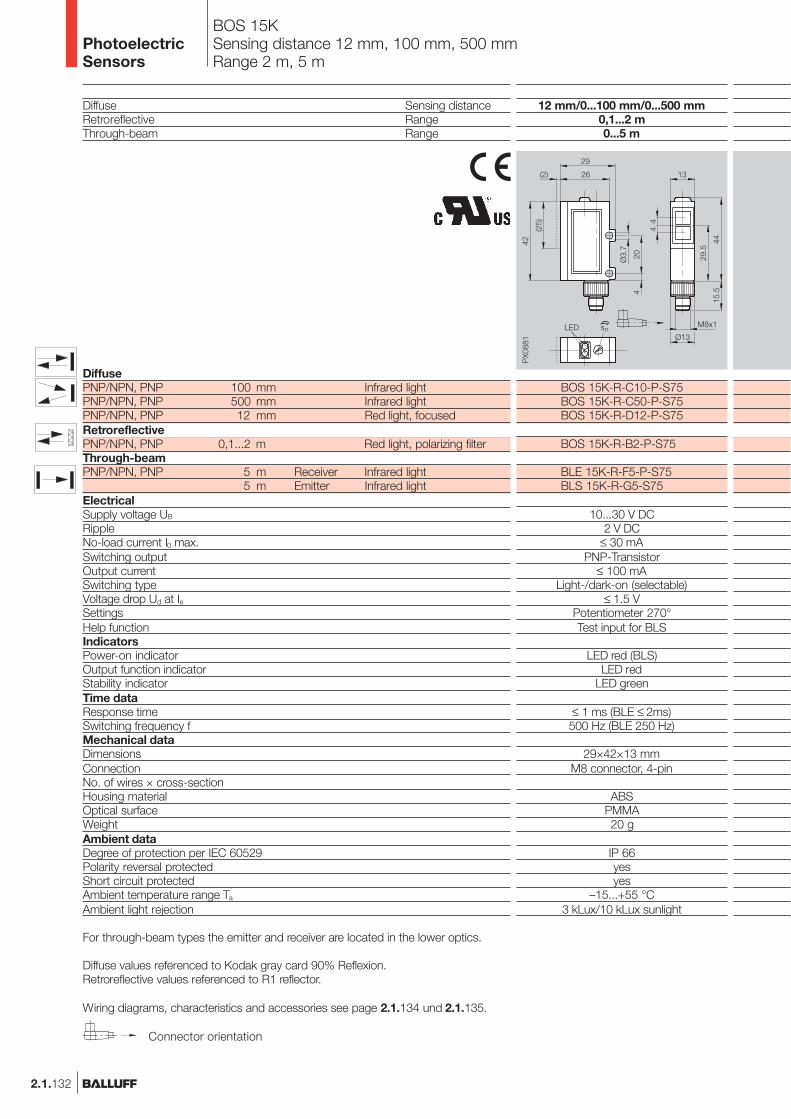
2.1.132
BOS 15KSensing distance 12 mm, 100 mm, 500 mmRange 2 m, 5 m
12 mm/0...100 mm/0...500 mm0,1...2 m0...5 m
BOS 15K-R-C10-P-S75BOS 15K-R-C50-P-S75BOS 15K-R-D12-P-S75
BOS 15K-R-B2-P-S75
BLE 15K-R-F5-P-S75BLS 15K-R-G5-S75
10...30 V DC2 V DC
≤ 30 mAPNP-Transistor
≤ 100 mALight-/dark-on (selectable)
≤ 1.5 VPotentiometer 270°Test input for BLS
LED red (BLS)LED red
LED green
≤ 1 ms (BLE ≤ 2ms)500 Hz (BLE 250 Hz)
29×42×13 mmM8 connector, 4-pin
ABSPMMA20 g
IP 66yesyes
–15...+55 °C3 kLux/10 kLux sunlight
Diffuse Sensing distanceRetroreflective RangeThrough-beam Range
DiffusePNP/NPN, PNP 100 mm Infrared lightPNP/NPN, PNP 500 mm Infrared lightPNP/NPN, PNP 12 mm Red light, focusedRetroreflectivePNP/NPN, PNP 0,1...2 m Red light, polarizing filterThrough-beamPNP/NPN, PNP 5 m Receiver Infrared light
5 m Emitter Infrared lightElectricalSupply voltage UB
RippleNo-load current I0 max.Switching outputOutput currentSwitching typeVoltage drop Ud at IeSettingsHelp functionIndicatorsPower-on indicatorOutput function indicatorStability indicatorTime dataResponse timeSwitching frequency fMechanical dataDimensionsConnectionNo. of wires × cross-sectionHousing materialOptical surfaceWeightAmbient dataDegree of protection per IEC 60529Polarity reversal protectedShort circuit protectedAmbient temperature range Ta
Ambient light rejection
For through-beam types the emitter and receiver are located in the lower optics.
Diffuse values referenced to Kodak gray card 90% Reflexion.Retroreflective values referenced to R1 reflector.
Wiring diagrams, characteristics and accessories see page 2.1.134 und 2.1.135.
Connector orientation
PhotoelectricSensors

2.1.133
BOS 15KSensing distance 12, 100,500 mm, Range 2 m, 5 m
12 mm/0...100 mm/0...500 mm0,1...2 m0...5 m
BOS 15K-S-C10-P-S75BOS 15K-S-C50-P-S75BOS 15K-S-D12-P-S75
BOS 15K-S-B2-P-S75
BLE 15K-S-F5-P-S75BLS 15K-S-G5-S75
10...30 V DC2 V DC
≤ 30 mAPNP-Transistor
≤ 100 mALight-/dark-on (selectable)
≤ 1.5 VPotentiometer 270°Test input for BLS
LED red (BLS)LED red
LED green
≤ 1 ms (BLE ≤ 2ms)500 Hz (BLE 250 Hz)
44×26×13 mmM8 connector, 4-pin
ABSPMMA20 g
IP 66yesyes
–15...+55 °C3 kLux/10 kLux sunlight
12 mm/0...100 mm/0...500 mm0,1...2 m0...5 m
BOS 15K-R-C10-02BOS 15K-R-C50-02BOS 15K-R-D12-02
BOS 15K-R-B2-02
BLE 15K-R-F5-02BLS 15K-R-G5-02
10...30 V DC2 V DC
≤ 30 mAPNP- and NPN-Transistor selectable
≤ 100 mALight-/dark-on (selectable)
≤ 1.5 VPotentiometer 270°Test input for BLS
LED red (BLS)LED red
LED green
≤ 1 ms (BLE ≤ 2ms)500 Hz (BLE 250 Hz)
29×42×13 mm2 m cable, PVC4/5/6×0.34 mm²
ABSPMMA90 g
IP 66yesyes
–15...+55 °C3 kLux/10 kLux sunlight
12 mm/0...100 mm/0...500 mm0,1...2 m0...5 m
BOS 15K-S-C10-02BOS 15K-S-C50-02BOS 15K-S-D12-02
BOS 15K-S-B2-02
BLE 15K-S-F5-02BLS 15K-S-G5-02
10...30 V DC2 V DC
≤ 30 mAPNP- and NPN-Transistor selectable
≤ 100 mALight-/dark-on (selectable)
≤ 1.5 VPotentiometer 270°Test input for BLS
LED red (BLS)LED red
LED green
≤ 1 ms (BLE ≤ 2ms)500 Hz (BLE 250 Hz)
44×26×13 mm2 m cable, PVC4/5/6×0.34 mm²
ABSPMMA90 g
IP 66yesyes
–15...+55 °C3 kLux/10 kLux sunlight
2.1
2.3
www.balluff.com
5
PhotoelectricSensors
PhotoelectricSensorsAccessoriesPage 2.3.2 ...
Connectors ...Page 5.2 ...

BOS 15KFunction diagramsWiring
2.1.134
Retroreflective BOS 15K-..-B2-...
Wiring diagramsDiffuse BOS 15K-..-C10-...Kodakgray card90 %Reflexion
Range measured with side approach of Kodak gray card.
Diffuse BOS 15K-..-C50-...Kodakgray card90 %Reflexion
Range measured with side approach of Kodak gray card.
Diffuse with focused beam BOS 15K-..-D12-...
Range measured with side approach of Kodak gray card.
ReflectorBOS R-1
Range measured with side approach of reflector.
Through-beam BLE/BLS 15K-...
For the through-beam sensor the maximum possible offset betweenemitter and receiver is measured.
Transmitter/Receiver
Kodak gray card90 % Reflexion
Öffner Schließer
Öffner Schließer
Öffner Schließer
Öffner Schließer
Öffner Schließer
Kodak gray card18 % Reflexion
Kodak gray card18 % Reflexion
Kodakgray card18 %Reflexion
ReflectorBOS R-10
PhotoelectricSensors

BOS 15KDefinitionsAccessories
2.1.135
2.1
2.3
Alarm output for receiver(cable version only)
The receiver is equippedwith an alarm output.This signal output (PNP opencollector 30 mA) is usedto trigger a warning signalwhen there are function
stabile
unstable
stable
Switchingthreshold
Stability(green LED)
Alarm
disturbances which can becaused by contamination ormechanical maladjustment.The alarm output is activatedif the receive signal remainsin the alarm range for atleast 3 sec.
Test input for emitter
The test input interruptsthe light pulses from theemitter and thereby enablesa function check of thesensor.The receiver output mustswitch each time when thetest input shows a voltageof 10...30 V DC (Test+) or0 V DC (Test–) .
Contamination ormaladjustment on the opticalaxis causes the emittersignal to reach the receiveronly weakly, if at all.Therefore the output willnot switch, even though thetest input is activated.The test function is a kindof remote monitoring of thesensor, thereby providingpreventive system checking.
Green Stability indicator
The "threshold energy"at which a signal change onthe output is effected isdefined as 100 %.The switching state isconsidered stable when theinput energy exceeds orfalls below the "thresholdenergy" by 30 %. The greenLED then comes on.
This results in the "safe"range,– when the input signal
exceeds a minimum of130 % of the thresholdenergy
– when the input signal fallsbelow a minimum of 70 %of the threshold energy.
Output(red LED)
Dar
k-on
Ligh
t-on
stabile
unstable
stable
Switchingthreshold
Stability(green LED)
Reflector BOS R-10(supplied with retroreflectivesensors)
Slit apertures(supplied with through-beam sensors)
Slit width 0.5 mm 1 mm 2 mmRange 0.5 m 1 m 2 mObject size > 0.5 mm > 1 mm > 2 mm
Mounting bracket(supplied)
Recommendedaccessoriesplease order separately
ConnectorBKS-S 74/BKS-S 75
www.balluff.com
5
PhotoelectricSensors
PhotoelectricSensorsAccessoriesPage 2.3.2 ...
Connectors ...Page 5.2 ...

2.1.136
BOS 21M
BOS 21M – a completefamily in a compact, toughmetal housing.Comprehensive functionality,use of the most modernsensor technologies andinnovative manufacturingtechnology leave nothing tobe desired for versatileapplication in robotics andautomation, packaging,assembly and handling.
Teach-in switches andpotentiometers assure faststartup as well as simple andeconomical operation of thesensor.
A wide range of accessoriessuch as mounting brackets,stands, dovetail clamps etc.enable variable attachment ofthe products in any position.
PhotoelectricSensors

2.1.137
Photoelectricsensorsaccessoriespage 2.3.2 ...
2.1
2.3
BOS 21MProduct Overview
Type
Diffusewith HGA
BOS 21M-PUS-LH12-S4BOS 21M-NUS-LH12-S4
BOS 21M-PUS-RH12-S4BOS 21M-NUS-RH12-S4
BOS 21M-PUS-RV13-S4BOS 21M-NUS-RV13-S4
DiffuseBOS 21M-PA-RD10-S4BOS 21M-NA-RD10-S4
BOS 21M-PA-ID10-S4BOS 21M-NA-ID10-S4
BOS 21M-PA-LD10-S4BOS 21M-NA-LD10-S4
RetroreflectiveBOS 21M-PA-PR10-S4BOS 21M-NA-PR10-S4
BOS 21M-PA-LR10-S4BOS 21M-NA-LR10-S4
BOS 21M-PA-PK10-S4BOS 21M-NA-PK10-S4
BOS 21M-PA-PT10-S4BOS 21M-NA-PT10-S4
Through-beamBOS 21M-PA-IE10-S4BOS 21M-NA-IE10-S4
BOS 21M-PA-LE10-S4BOS 21M-NA-LE10-S4
BOS 21M-XT-IS11-S4BOS 21M-XT-LS11-S4
OutputLight typeSensingdistance/range
50...100 mm50...100 mm
70...200 mm70...200 mm
70...200 mm70...200 mm
0.01...1 m0.01...1 m
0.05...2 m0.05...2 m
0...600 mm0...600 mm
0.1...8 m0.1...8 m
0.1...20 m0.1...20 m
0...4 m0...4 m
0...2 m0...2 m
0...20 m0...20 m
0...60 m0...60 m
0...20 m0...60 m
Connec-tion
1 kHz1 kHz
1 kHz1 kHz
1 kHz1 kHz
500 Hz500 Hz
500 Hz500 Hz
2 kHz2 kHz
1 kHz1 kHz
2 kHz2 kHz
1 kHz1 kHz
1 kHz1 kHz
500 Hz500 Hz
1.5 kHz1.5 kHz
Outputfunction
Specialfeatures
Red
ligh
t
Infr
ared
M12
con
nect
or, 4
-pin
10...
30 V
DC
Teac
h-in
NP
N-T
rans
isto
r
PN
P-T
rans
isto
r
Ligh
t-on
Dar
k-on
Aut
ocol
limat
ion
UBSwitchingfrequency
Lase
r lig
ht
Page
2.1.1422.1.142
2.1.1382.1.138
2.1.1392.1.139
2.1.1392.1.139
2.1.1392.1.139
2.1.1432.1.143
2.1.1402.1.140
2.1.1432.1.143
2.1.1412.1.141
2.1.1412.1.141
2.1.1412.1.141
2.1.1432.1.143
2.1.1412.1.143
Gla
ss s
ensi
ng
Pol
ariz
ing
filte
r
www.balluff.com
Connectors ...page 5.2 ...
5
PhotoelectricSensors

2.1.138
BOS 21MSensing distance 200 mm
Diffuse with background suppression Sensing distanceDiffuse with foreground suppression Sensing distanceDiffuse Sensing distance
DiffusePNP 70...200 mm HGANPN 70...200 mm HGAPNP 70...200 mm VGA + HGANPN 70...200 mm VGA + HGAPNP 0.01...1 mNPN 0.01...1 mPNP 0.05...2 mNPN 0.05...2 mElectrical dataSupply voltage UB
RippleNo-load supply current I0 max.Switching outputOutput currentSwitching typeVoltage drop Ud at IeSettingsOptical dataRecommended sensing distanceEmitter, light typeWavelengthIndicatorsOutput function indicatorStability indicatorTime dataResponse timeSwitching frequency fMechanical dataDimensionsConnectionHousing materialOptical surfaceWeightAmbient dataDegree of protection per IEC 60529Polarity reversal protectedShort circuit protectedAmbient temperature range Ta
Ambient light rejection
70...200 mm
BOS 21M-PUS-RH12-S4BOS 21M-NUS-RH12-S4
10...30 V DC≤ 2 V DC≤ 50 mA
PNP- or NPN-Transistor100 mA
Light-/dark-on (selectable)2 V
Teach-in
70...200 mmLED, red light
670 nm
LED yellowLED green/red
0.5 ms1 kHz
42.5×50×15 mmM12 connector, 4-pin
GD-Zn/AlPMMA76 g
IP 67yesyes
–10...+50 °C10 kLux
Em
itter
Rec
eive
r
rota
table
270
°
Diffuse values referenced to Kodak gray card 90% Reflexion.
Connector orientation
Wiring diagrams, characteristics and accessories see page 2.1.144 to 2.1.147.
PhotoelectricSensors

2.1.139
Photoelectricsensorsaccessoriespage 2.3.2 ...
2.1
2.3
BOS 21MSensing distance 200 mm,1 m, 2 m
70...200 mm
BOS 21M-PUS-RV13-S4BOS 21M-NUS-RV13-S4
10...30 V DC≤ 2 V DC≤ 50 mA
PNP- or NPN-Transistor100 mA
Light-/dark-on (selectable)2 V
Teach-in
70...200 mmLED, red light
670 nm
LED yellowLED green
0.5 ms1 kHz
42.5×50×15 mmM12 connector, 4-pin
GD-Zn/AlPMMA76 g
IP 67yesyes
–10...+50 °C10 kLux
0.01...1 m
BOS 21M-PA-RD10-S4BOS 21M-NA-RD10-S4
10...30 V DC≤ 2 V DC≤ 35 mA
PNP- or NPN-Transistor100 mA
Light-/dark-on (push-pull)2 V
Potentiometer 270°
0.01...1 mLED, red light
650 nm
LED yellowLED green
1 ms500 Hz
42.5×50×15 mmM12 connector, 4-pin
GD-Zn/AlPMMA76 g
IP 67yesyes
–25...+55 °C10 kLux
0.05...2 m
BOS 21M-PA-ID10-S4BOS 21M-NA-ID10-S4
10...30 V DC≤ 2 V DC≤ 35 mA
PNP- or NPN-Transistor100 mA
Light-/dark-on (push-pull)2 V
Potentiometer 270°
0.05...2 mLED, infrared
880 nm
LED yellowLED green
1 ms500 Hz
42.5×50×15 mmM12 connector, 4-pin
GD-Zn/AlPMMA76 g
IP 67yesyes
–25...+55 °C10 kLux
Em
itter
Rec
eive
r
rota
table
270
°
Em
itter
Rec
eive
r
rota
table
270
°
Em
itter
Rec
eive
r
rota
table
270
°
www.balluff.com
Connectors ...page 5.2 ...
5
PhotoelectricSensors

2.1.140
BOS 21MRange 8 m
Retroreflective with polarizing filter RangeRetroreflective Autocollimation RangeRetroreflective for glass sensing RangeThrough-beam Range
RetroreflectivePNP 0.1...8 m Polarizing filterNPN 0.1...8 m Polarizing filterPNP 4 m Polarizing filter, autocollimationNPN 4 m Polarizing filter, autocollimationPNP 2 m Polarizing filter, autocollimation, glass sensingNPN 2 m Polarizing filter, autocollimation, glass sensingThrough-beamPNP 20 m ReceiverNPN 20 m Receiver
20 m EmitterElectrical dataSupply voltage UB
RippleNo-load supply current I0 max.Switching outputOutput currentSwitching typeVoltage drop Ud at IeSettingsHelp functionsOptical dataRecommended rangeEmitter, light typeWavelengthIndicatorsPower-on indicatorOutput function indicatorStability indicatorTime dataResponse timeSwitching frequency fMechanical dataDimensionsConnectionHousing materialOptical surfaceWeightAmbient dataDegree of protection per IEC 60529Polarity reversal protectedShort circuit protectedAmbient temperature range Ta
Ambient light rejection
0.1...8 m
BOS 21M-PA-PR10-S4BOS 21M-NA-PR10-S4
10...30 V DC≤ 2 V DC≤ 35 mA
PNP- or NPN-Transistor100 mA
Light-/dark-on (push-pull)2 V
Potentiometer 270°
0.1...8 mLED, red light
650 nm
LED yellowLED green
0.5 ms1 kHz
42.5×50×15 mmM12 connector, 4-pin
GD-Zn/AlPMMA76 g
IP 67yesyes
–25...+55 °C10 kLux
rota
table
270
°
Rec
eive
rE
mitt
er
Retroreflective values referenced to R1 reflector.
Connector orientation
Wiring diagrams, characteristics and accessories see page 2.1.144 to 2.1.147.
PhotoelectricSensors

2.1.141
Photoelectricsensorsaccessoriespage 2.3.2 ...
2.1
2.3
BOS 21MRange 2 m, 4 m, 20 m
0...4 m
BOS 21M-PA-PK10-S4BOS 21M-NA-PK10-S4
10...30 V DC≤ 2 V DC≤ 35 mA
PNP- or NPN-Transistor100 mA
Light-/dark-on (push-pull)2 V
Potentiometer 270°
0...4 mLED, red light
650 nm
LED yellowLED green
0.5 ms1 kHz
42.5×50×15 mmM12 connector, 4-pin
GD-Zn/AlGlass78 g
IP 67yesyes
–25...+55 °C10 kLux
0...2 m
BOS 21M-PA-PT10-S4BOS 21M-NA-PT10-S4
10...30 V DC≤ 2 V DC≤ 35 mA
PNP- or NPN-Transistor100 mA
Light-/dark-on (push-pull)2 V
Potentiometer 270°
0...2 mLED, red light
650 nm
LED yellow
0.5 ms1 kHz
42.5×50×15 mmM12 connector, 4-pin
GD-Zn/AlGlass*78 g
IP 67yesyes
–25...+55 °C10 kLux
*also available with PMMA
0...20 m
BOS 21M-PA-IE10-S4BOS 21M-NA-IE10-S4BOS 21M-XT-IS11-S4
10...30 V DC≤ 2 V DC≤ 35 mA
PNP- or NPN-Transistor100 mA
Light-/dark-on (push-pull)2 V
Potentiometer 270°Test input (emitter)
0...20 mLED, infrared
880 nm
LED green (emitter)LED yellow (receiver)LED green (receiver)
1 ms500 Hz
42.5×50×15 mmM12 connector, 4-pin
GD-Zn/AlPMMA75 g
IP 67yesyes
–25...+55 °C10 kLux
optic
al a
xis
rota
table
270
°
optic
al a
xis
rota
table
270
°
Em
itter
Rec
eive
r
rota
table
270
°
www.balluff.com
Connectors ...page 5.2 ...
5
PhotoelectricSensors

2.1.142
BOS 21MSensing distance 100 mm
Diffuse with background suppression Sensing distanceDiffuse Sensing distanceRetroreflective with polarizing filter RangeThrough-beam Range
DiffusePNP 50...100 mm HGANPN 50...100 mm HGAPNP 600 mmNPN 600 mmRetroreflectivePNP 0.1...20 m Polarizing filterNPN 0.1...20 m Polarizing filterThrough-beamPNP 60 m ReceiverNPN 60 m Receiver
60 m EmitterElectrical dataSupply voltage UB
RippleNo-load supply current I0 max.Switching outputOutput currentSwitching typeVoltage drop Ud at IeSettingsHelp functionsOptical dataRecommended sensing distance/rangeEmitter, light typeWavelengthLaser classIndicatorsPower-on indicatorOutput function indicatorStability indicatorTime dataResponse timeSwitching frequency fMechanical dataDimensionsConnectionHousing materialOptical surfaceWeightAmbient dataDegree of protection per IEC 60529Polarity reversal protectedShort circuit protectedAmbient temperature range Ta
Ambient light rejection
50...100 mm
BOS 21M-PUS-LH12-S4BOS 21M-NUS-LH12-S4
10...30 V DC≤ 2 V DC60 mA
PNP- or NPN-Transistor100 mA
Light-/dark-on (selectable)2 V
Teach-in
50...100 mmLaser, red light
650 nm1
LED yellowLED green/red
0.5 ms1 kHz
42.5×50×15 mmM12 connector, 4-pin
GD-Zn/AlPMMA77 g
IP 67yesyes
–10...+50 °C5 kLux
Em
itter
Rec
eive
r
rota
table
270
°
Diffuse values referenced to Kodak gray card 90% Reflexion.Retroreflective values referenced to R1 reflector.
Connector orientation
PhotoelectricSensors

2.1.143
Photoelectricsensorsaccessoriespage 2.3.2 ...
2.1
2.3
BOS 21MSensing distance 600 mmRange 20 m, 60 mLaser
0.1...20 m
BOS 21M-PA-LR10-S4BOS 21M-NA-LR10-S4
10...30 V DC≤ 2 V DC35 mA
PNP- or NPN-Transistor100 mA
Light-/dark-on (push-pull)2 V
Potentiometer 270°
0.1...20 mLaser, red light
650 nm1
LED greenLED yellow
0.25 ms2 kHz
42.5×50×15 mmM12 connector, 4-pin
GD-Zn/AlPMMA77 g
IP 67yesyes
–10...+50 °C5 kLux
0...60 m
BOS 21M-PA-LE10-S4BOS 21M-NA-LE10-S4BOS 21M-XT-LS11-S4
10...30 V DC≤ 2 V DC35 mA
PNP- or NPN-Transistor100 mA
Light-/dark-on (push-pull)2 V
Potentiometer 270°Test input (emitter)
0...60 mmLaser, red light
650 nm1
LED greenLED yellow
0.33 ms1.5 kHz
42.5×50×15 mmM12 connector, 4-pin
GD-Zn/AlPMMA76 g
IP 67yesyes
–10...+50 °C5 kLux
0...600 mm
BOS 21M-PA-LD10-S4BOS 21M-NA-LD10-S4
10...30 V DC≤ 2 V DC35 mA
PNP- or NPN-Transistor100 mA
Light-/dark-on (push-pull)2 V
Potentiometer 270°
0...600 mmLaser, red light
650 nm1
LED greenLED yellow
0.25 ms2 kHz
42.5×50×15 mmM12 connector, 4-pin
GD-Zn/AlPMMA77 g
IP 67yesyes
–10...+50 °C5 kLux
Em
itter
Rec
eive
r
rota
table
270
°
Em
itter
Rec
eive
r
rota
table
270
°
Em
itter
Rec
eive
r
rota
table
270
°
Wiring diagrams, characteristics and accessories see page 2.1.144 to 2.1.147.
www.balluff.com
Connectors ...page 5.2 ...
5
PhotoelectricSensors
2.1.144
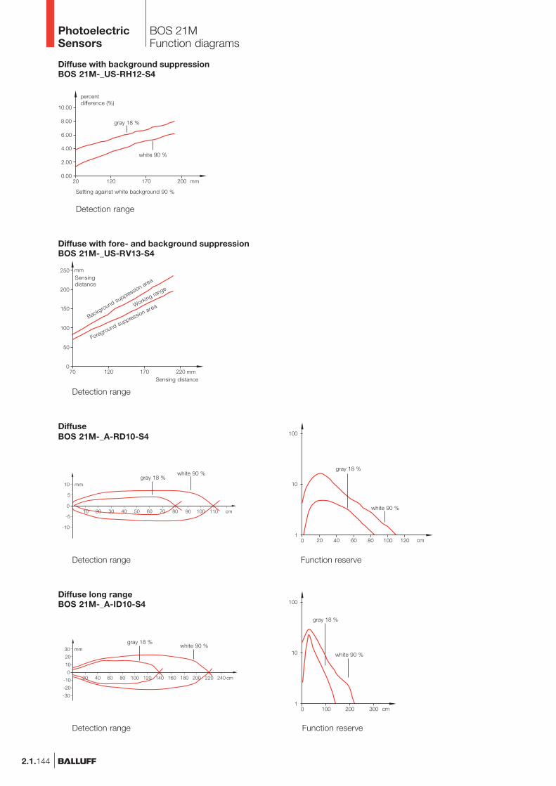
BOS 21MFunction diagrams
Diffuse long rangeBOS 21M-_A-ID10-S4
Detection range
white 90 %
gray 18 %
Function reserve
white 90 %gray 18 %
DiffuseBOS 21M-_A-RD10-S4
Detection range
white 90 %
gray 18 %
Function reserve
white 90 %gray 18 %
Diffuse with fore- and background suppressionBOS 21M-_US-RV13-S4
Detection range
Background suppression area
Sensing distance
Sensingdistance
Foreground suppression areaWorking range
Diffuse with background suppressionBOS 21M-_US-RH12-S4
Detection range
Setting against white background 90 %
percentdifference (%)
white 90 %
gray 18 %
PhotoelectricSensors

2.1.145
Photoelectricsensorsaccessoriespage 2.3.2 ...
2.1
2.3
BOS 21MFunction diagrams
Retroreflective polarizedBOS 21M-_A-PR10-S4
Detection range
R1
R1
Function reserve
Retroreflective autocollimationBOS 21M-_A-PK10-S4
Function reserve
R1
Detection range
R1
Retroreflective glass sensingBOS 21M-_A-PT10-S4
Resolution
R1
Detection range
R1
Through-beamBOS 21M-_A-IE10-S4
Detection range Function reserve
www.balluff.com
Connectors ...page 5.2 ...
5
PhotoelectricSensors

2.1.146
BOS 21MFunction diagrams
Laser through-beamBOS 21M-_A-LE10-S4
Laser retroreflective polarizedBOS 21M-_A-LR10-S4
Detection range
R1
Resolution
Resolution
Laser diffuseBOS 21M-_A-LD10-S4
Detection range
white 90 %
gray 18 %
Laser diffuse with background suppressionBOS 21M-_US-LH12-S4
Setting against white background 90 %
Percentdifference (%)
white 90 %
gray 18 %
Tolerance with standard setting
Detection range Resolution
PhotoelectricSensors

2.1.147
Photoelectricsensorsaccessoriespage 2.3.2 ...
2.1
2.3
BOS 21MConnectionAccessories
Recommended accessoriesplease order separately
Mounting clampBOS 21-KH-1
Mounting clampBOS 21-KH-2
Mounting bracketBOS 21-HW-1
Mounting bracketBOS 21-HW-2
Holding systemBOS 21-HS-1
ReflectorBOS R-1
ConnectorBKS-_ 19/BKS-_ 20
Adapter plateBOS 21-AD-1
ReflectorBOS R-9
Wiring diagrams
BOS 21M-PA-... BOS 21M-PUS-...
BOS 21M-NA-... BOS 21M-NUS-...
BOS 21M-XT-...
www.balluff.com
Connectors ...page 5.2 ...
5
PhotoelectricSensors

2.1.148
BOS 26K
The BOS 26K seriesrepresents the logicaldevelopment of an alreadysuccessful design: a uniformhousing for all sensortypes used. This makes theBOS 26K series compatiblewith series BOS 25K andcomplements it withnew kinds of sensors withparticular specifications andfeatures:
– Laser sensors– New, high-performance
red light and infraredsensors
– Additional optical andmechanical functions.
The BOS 26K series isideally suited wherevergreater demands are madein terms of precision,handling, high sensingdistance or range, as wellas small-parts detection.
The retroreflective modelsfeature autocollimation,i.e., the emitter andreceiver beams coincidegeometrically.Advantage: Exact switchingpoints for any desiredside-approaching object inthe entire beam path
The diffuse model withbackground suppressionBOS 26K-..-1LHB,with its focused light beam,can detect objects preciselyin virtually any color between30 and 150 mm. Thefocusing feature enables aspot size of just 0.1 mmat a distance of 80 mm.
Features
– Rotatable M12 connector– Precise setting
mechanism with tworevolutions (720°)
– Clear character display forsensitivity setting
– Switching state andcontamination displayvisible any direction
– Complementary PNP orNPN output
– High switching frequencyfor laser version
Applications
– Precise small partdetection
– Positioning tasks– Detail checking– Conveyor inspection
(background suppression)– Conveying– Automation– Handling equipment,
Robotics– Machine tool building– Specialty machines
PhotoelectricSensors

2.1.149
BOS 26KProduct Overview
2.1
Photoelectricsensorsaccessoriespage 2.3.2 ...
2.3
Type
Diffuse with HGABOS 26K-PA-1LHA-SA1-S4-CBOS 26K-NA-1LHA-SA1-S4-C
BOS 26K-PA-1LHB-S4-CBOS 26K-NA-1LHB-S4-C
BOS 26K-PA-1HC-S4-CBOS 26K-NA-1HC-S4-CBOS 26K-PA-1LHC-S4-CBOS 26K-NA-1LHC-S4-C
BOS 26K-PA-1IE-S4-CBOS 26K-NA-1IE-S4-C
RetroreflectiveBOS 26K-PA-1QE-S4-CBOS 26K-NA-1QE-S4-CBOS 26K-PO-1QE-SA1-C
BOS 26K-PA-1LQP-S4-CBOS 26K-NA-1LQP-S4-C
OutputLight typeSensingdistance/Range
40...60 mm40...60 mm
30...150 mm30...150 mm
30...300 mm30...300 mm50...300 mm50...300 mm
150...600 mm150...600 mm
0...5.5 m0...5.5 m0...5.5 m
0...20 m0...20 m
Connec-tion
2.5 kHz2.5 kHz
2.5 kHz2.5 kHz
1 kHz1 kHz
2.5 kHz2.5 kHz
800 Hz800 Hz
1 kHz1 kHz1 kHz
2.5 kHz2.5 kHz
Outputfunction
Page
2.1.1522.1.152
2.1.1532.1.153
2.1.1502.1.1502.1.1532.1.153
2.1.1512.1.151
2.1.1512.1.1512.1.151
2.1.1532.1.153
Helpfunctions
Red
ligh
t
Infra
red
M12
con
nect
or, 4
-pin
10...
30 V
DC
Pol
ariz
ing
filte
r
NP
N-T
rans
isto
r
PN
P-T
rans
isto
r
Ligh
t-on
Dar
k-on
Aut
ocol
limat
ion
UBSwitchingfrequency
Lase
r
Ala
rm o
utpu
t
Connectors ...page 5.2 ...
5
www.balluff.com
PhotoelectricSensors

2.1.150
Visualization
rotatable 270°
BOS 26KSensing distance 300 mm
Rec
eive
rE
mitt
er
Diffuse with background suppression Sensing distance
Retroreflective with polarizing filter Range
DiffusePNP 30...300 mm HGANPN 30...300 mm HGAPNP 150...600 mm HGANPN 150...600 mm HGARetroreflectivePNP 5.5 m AutocollimationNPN 5.5 m AutocollimationElectrical dataSupply voltage UB
RippleNo-load supply current I0 max.Switching outputOutput currentSwitching typeVoltage drop Ud at IeSettingsHelp functionsOptical dataEmitter, light typeWavelengthLight spot diameterDistance hysteresis (18 %/18 %)Gray value shift (90 %/18 %)IndicatorsPower-on indicatorOutput function indicatorStability indicatorTime dataResponse timeSwitching frequency fMechanical dataDimensionsConnectionHousing materialOptical surfaceWeightAmbient dataDegree of protection per IEC 60529Polarity reversal protectedShort circuit protectedAmbient temperature range Ta
Ambient light rejection per
Diffuse values referenced to Kodak gray card 90% Reflexion.Retroreflective values referenced to R1 reflector.
30...300 mm
BOS 26K-PA-1HC-S4-CBOS 26K-NA-1HC-S4-C
10...30 V DC10 %
≤ 35 mAPNP- or NPN-Transistor
200 mALight-/dark-on (complementary)
≤ 2.4 V2-turn potentiometer with indicator
LED, red light, pulsed660 nm
approx. 8 mm at 200 mm� 5 %� 8 %
LED greenLED yellow
LED red
0.5 ms1 kHz
50×50×17 mmM12 connector, 4-pinImpact-resistant ABS
PMMA35 g
IP 67yesyes
–20...+60 °CEN 60947-5-2
Wiring diagrams, characteristics and accessories see page 2.1.154 and 2.1.155.
PhotoelectricSensors
�

150...600 mm
BOS 26K-PA-1IE-S4-CBOS 26K-NA-1IE-S4-C
10...30 V DC10 %
≤ 70 mAPNP- or NPN-Transistor
200 mALight-/dark-on (complementary)
≤ 2.4 V2-turn potentiometer with indicators
LED, infrared, pulsed880 nm
approx. 20 mm at 400 mm� 5 %� 12 %
LED greenLED yellow
LED red
0.625 ms800 Hz
50×50×17 mmM12 connector, 4-pinImpact-resistant ABS
PMMA35 g
IP 67yesyes
–20...+60 °CEN 60947-5-2
2.1.151
0...5.5 m
BOS 26K-PA-1QE-S4-CBOS 26K-NA-1QE-S4-C
10...30 V DC10 %
≤ 30 mAPNP- or NPN-Transistor
200 mALight-/dark-on (complementary)
≤ 2.4 V2-turn potentiometer with indicator
LED, red light, pulsed660 nm
LED greenLED yellow
LED red
0.5 ms1 kHz
50×50×17 mmM12 connector, 4-pinImpact-resistant ABS
PMMA35 g
IP 67yesyes
–20...+60 °CEN 60947-5-2
BOS 26KSensing distance 600 mmRange 5.5 m
rotatable 270° rotatable 270°
2.1
Photoelectricsensorsaccessoriespage 2.3.2 ...
2.3
Visualization
Rec
eive
rE
mitt
er
Visualization
optic
al a
xis
0...5.5 m
BOS 26K-PO-1QE-SA1-C
10...30 V DC10 %
≤ 30 mAPNP-Transistor
200 mALight-on≤ 2.4 V
2-turn potentiometer with indicatorContamination output
LED, red light, pulsed660 nm
LED greenLED yellow
LED red
0.5 ms1 kHz
50×50×17 mmM12 connector, 4-pinImpact-resistant ABS
PMMA35 g
IP 67yesyes
–20...+60 °CEN 60947-5-2
rotatable 270°
Visualization
optic
al a
xis
Connector orientation
www.balluff.com
Connectors ...page 5.2 ...
5
PhotoelectricSensors
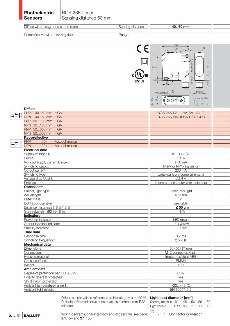
BOS 26K LaserSensing distance 60 mm
Diffuse with background suppression Sensing distance
Retroreflective with polarizing filter Range
DiffusePNP 40...60 mm HGANPN 40...60 mm HGAPNP 30...150 mm HGANPN 30...150 mm HGAPNP 50...300 mm HGANPN 50...300 mm HGARetroreflectivePNP 20 m AutocollimationNPN 20 m AutocollimationElectrical dataSupply voltage UB
RippleNo-load supply current I0 max.Switching outputOutput currentSwitching typeVoltage drop Ud at IeSettingsOptical dataEmitter, light typeWavelengthLaser classLight spot diameterDistance hysteresis (18 %/18 %)Gray value shift (90 %/18 %)IndicatorsPower-on indicatorOutput function indicatorStability indicatorTime dataResponse timeSwitching frequency fMechanical dataDimensionsConnectionHousing materialOptical surfaceWeightAmbient dataDegree of protection per IEC 60529Polarity reversal protectedShort circuit protectedAmbient temperature range Ta
Ambient light rejection
Diffuse sensor values referenced to Kodak gray card 90 %Reflexion. Retroreflective sensor values referenced to R22reflector.
Wiring diagrams, characteristics and accessories see page2.1.154 and 2.1.155.
2.1.152 Connector orientation
40...60 mm
BOS 26K-PA-1LHA-SA1-S4-CBOS 26K-NA-1LHA-SA1-S4-C
10...30 V DC10 %
≤ 50 mAPNP- or NPN-Transistor
200 mALight-/dark-on (complementary)
≤ 2.4 V2-turn potentiometer with indicators
Laser, red light670 nm
2see table� ≤≤≤≤≤ 50 µm
� 1 %
LED greenLED yellow
LED red
0.2 ms2.5 kHz
50×50×17 mmM12 connector, 4-pinImpact-resistant ABS
PMMA40 g
IP 67yesyes
–20...+45 °CEN 60947-5-2
Light spot diameter [mm]Sensing distance 40 45 50 55 60Light spot-∅ 0.25 0.7 1.1 1.5 1.8
Visualization
rotatable 270°
Rec
eive
rE
mitt
er
PhotoelectricSensors
�
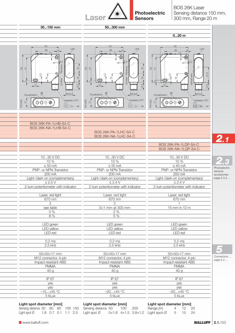
50...300 mm
BOS 26K-PA-1LHC-S4-CBOS 26K-NA-1LHC-S4-C
10...30 V DC10 %
≤ 50 mAPNP- or NPN-Transistor
200 mALight-/dark-on (complementary)
≤ 2.4 V2-turn potentiometer with indicator
Laser, red light670 nm
23×1 mm at 300 mm
� 2 %� 5 %
LED greenLED yellow
LED red
0.2 ms2.5 kHz
50×50×17 mmM12 connector, 4-pinImpact-resistant ABS
PMMA40 g
IP 67yesyes
–20...+45 °C5 kLux
BOS 26K LaserSensing distance 150 mm,300 mm, Range 20 m
2.1
Photoelectricsensorsaccessoriespage 2.3.2 ...
2.3
Rec
eive
rE
mitt
er
Visualization
rotatable 270°
Visualization
rotatable 270°
optic
al a
xis
2.1.153
Light spot diameter [mm]Sensing distance 50 100 200Light spot ∅ 5×1.8 4×1.5 3.8×1.2
Laser
www.balluff.com
Light spot diameter [mm]Range (m) 4 12 20Light spot-∅ 5 15 24
Connectors ...page 5.2 ...
5
0...20 m
BOS 26K-PA-1LQP-S4-CBOS 26K-NA-1LQP-S4-C
10...30 V DC10 %
≤ 40 mAPNP- or NPN-Transistor
200 mALight-/dark-on (complementary)
≤ 2.4 V2-turn potentiometer with indicator
Laser, red light670 nm
115 mm in 12 m
LED greenLED yellow
LED red
0.2 ms2.5 kHz
50×50×17 mmM12 connector, 4-pinImpact-resistant ABS
PMMA40 g
IP 67yesyes
–20...+45 °C5 kLux
30...150 mm
BOS 26K-PA-1LHB-S4-CBOS 26K-NA-1LHB-S4-C
10...30 V DC10 %
≤ 50 mAPNP- or NPN-Transistor
200 mALight-/dark-on (complementary)
≤ 2.5 V2-turn potentiometer with indicator
Laser, red light670 nm
2see table� 5 %� 8 %
LED greenLED yellow
LED red
0.2 ms2.5 kHz
50×50×17 mmM12 connector, 4-pinImpact-resistant ABS
PMMA40 g
IP 67yesyes
–15...+45 °C5 kLux
Visualization
rotatable 270°
Rec
eive
rE
mitt
er
Light spot diameter [mm]Sensing distance 30 60 80 100 150Light spot ∅� 1.8 0.7 0.1 1.1 2.5
PhotoelectricSensors

2.1.154
BOS 26KFunction Diagrams
Diffuse BOS 26K-..-1HC-...
Diffuse BOS 26K-..-1IE-...
Kodak gray card90 % Reflexion
Retroreflective BOS 26K-..-1QE-...
ReflectorBOS R-1
Kodak gray card90 % Reflexion
Diffuse BOS 26K-..-1LHB-...
Kodak gray card90 % Reflexion
Sensing distance measured with side approach of Kodak gray card.
Range measured using side approach with reflector.
Sensing distance measured with side approach of Kodak gray card.
Sensing distance measured with side approach of Kodak gray card.
Light beam geometry BOS 26K...1LHC
Light beam geometry BOS 26K...1LHB
PhotoelectricSensors

BOS 26KConnectionAccessories
2.1.155
Recommended accessoriesplease order separately
Mounting bracketBOS 26-HW-1
ConnectorBKS-_ 19/BKS-_ 20
ReflectorBOS R-1
ReflectorBOS R-9
2.1
Photoelectricsensorsaccessoriespage 2.3.2 ...
2.3
Wiring diagrams
Laser reflectorBOS R-12
Laser reflectorBOS R-13
Contamination indicator
The BOS 26K has 2 displayLED’s: yellow for indicatingfunction and green/redfor indicating status andcontamination. Should thereceived light drop belowa certain level, this will beindicated by a red LED. Thisallows contaminationor maladjustment to bedetected early.
Function indicator“Light at receiver“yellow LED
Power/Contaminationindicator, dual LED green/red
Switching state visualization
Sensitivity or range settingPotentiometer or spindle
Indicators and operating elements
www.balluff.com
Adapter plateBOS 21-AD-1
Laser reflectorBOS R-22
Connectors ...page 5.2 ...
5
PhotoelectricSensors

2.1.156
BOS 36K
The BOS 36K series isergonomic, compact(55×65×20 mm), and theconnector is rotatable.The performance data areoutstanding for a sensorthis size.An easily accessiblepotentiometer is used forsetting the sensitivity. Thediffuse model withbackground suppressionuses teach-in setting andvisible red light. This virtuallyprecludes any incorrectsetting.
Features
– Push-pull output 200 mA,short circuit protected
– Function and stabilityindicators
– Degree of protection IP 66– Compact plastic housing
(ABS)– Red light (background
suppressionand retroreflective)
– Teach-in (buttonbackground suppression)
– M12 connector, rotatable
Applications
– Wherever a higherperformance is needed
– Conveying andwarehousing
– Packaging machinery– Access control– Lift-type vehicles (not for
safety applications)– Wood industry– Ceramics industry– Automobile industry– Gate and door control
PhotoelectricSensorsPhotoelectricSensors

BOS 36KProduct Overview
2.1.157
Photoelectricsensorsaccessoriespage 2.3.2 ...
2.1
2.3
Type
Diffusewith HGA
BOS 36K-PA-1HD-S4-C
DiffuseBOS 36K-PA-1PH-S4-C
RetroreflectiveBOS 36K-PA-1QH-S4-C
Through-beamBLE 36K-PA-1PT-S4-C
BLS 36K-XX-1T-S4-C
OutputLighttype
Sensingdistance/range
100...500 mm
0,01...2 m
0,1...8 m
0...50 m
0...50 m
Connec-tion
500 Hz
500 Hz
500 Hz
500 Hz
Outputfunction
Page
2.1.158
2.1.159
2.1.159
2.1.159
2.1.159
Specialfeatures
Red
ligh
t
Infra
red
M12
con
nect
or, 4
-pin
Cab
le
10...
30 V
DC
Pol
ariz
ing
filte
r
NP
N-T
rans
isto
r
PN
P-T
rans
isto
r
Ligh
t-on
Dar
k-on
UBSwitchingfrequency
Teac
h-in
Test
inpu
t
www.balluff.com
Connectors ...page 5.2 ...
5
PhotoelectricSensorsPhotoelectricSensors
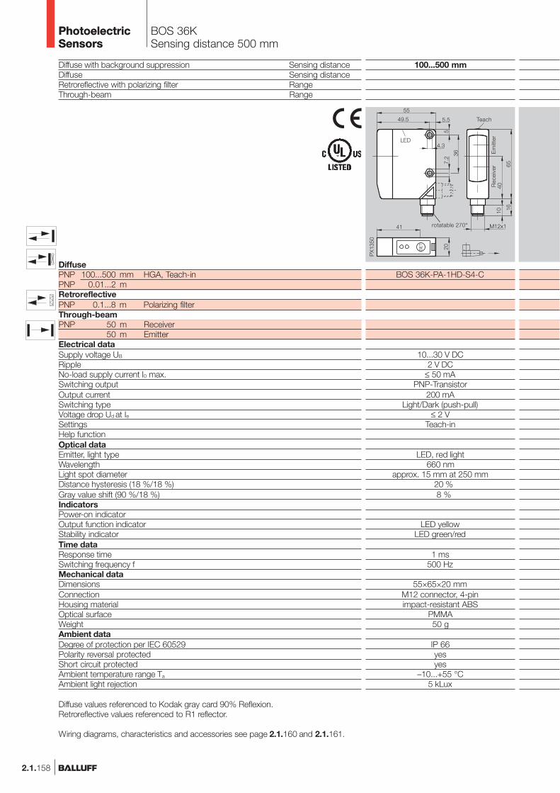
2.1.158
100...500 mm
BOS 36K-PA-1HD-S4-C
10...30 V DC2 V DC
≤ 50 mAPNP-Transistor
200 mALight/Dark (push-pull)
≤ 2 VTeach-in
LED, red light660 nm
approx. 15 mm at 250 mm� 20 %� 8 %
LED yellowLED green/red
1 ms500 Hz
55×65×20 mmM12 connector, 4-pinimpact-resistant ABS
PMMA50 g
IP 66yesyes
–10...+55 °C5 kLux
Diffuse with background suppression Sensing distanceDiffuse Sensing distanceRetroreflective with polarizing filter RangeThrough-beam Range
DiffusePNP 100...500 mm HGA, Teach-inPNP 0.01...2 mRetroreflectivePNP 0.1...8 m Polarizing filterThrough-beamPNP 50 m Receiver
50 m EmitterElectrical dataSupply voltage UB
RippleNo-load supply current I0 max.Switching outputOutput currentSwitching typeVoltage drop Ud at IeSettingsHelp functionOptical dataEmitter, light typeWavelengthLight spot diameterDistance hysteresis (18 %/18 %)Gray value shift (90 %/18 %)IndicatorsPower-on indicatorOutput function indicatorStability indicatorTime dataResponse timeSwitching frequency fMechanical dataDimensionsConnectionHousing materialOptical surfaceWeightAmbient dataDegree of protection per IEC 60529Polarity reversal protectedShort circuit protectedAmbient temperature range Ta
Ambient light rejection
Diffuse values referenced to Kodak gray card 90% Reflexion.Retroreflective values referenced to R1 reflector.
Wiring diagrams, characteristics and accessories see page 2.1.160 and 2.1.161.
BOS 36KSensing distance 500 mm
rotatable 270°
Teach
LED
Rec
eive
rE
mitt
er
PhotoelectricSensorsPhotoelectricSensors

2.1.159
2.1
Photoelectricsensorsaccessoriespage 2.3.2 ...
2.3
0...50 m
BLE 36K-PA-1PT-S4-CBLS 36K-XX-1T-S4-C
10...30 V DC2 V DC
≤ 40 mAPNP-Transistor
200 mALight/Dark (push-pull)
≤ 2 VPotentiometer 270°
Test input (BLS)
LED, infrared880 nm
LED green (BLS)LED yellow (BLE)LED green (BLE)
1 ms500 Hz
55×65×20 mmM12 connector, 4-pinimpact-resistant ABS
PMMA50 g
IP 66yesyes
–25...+55 °C5 kLux
0.1...8 m
BOS 36K-PA-1QH-S4-C
10...30 V DC2 V DC
≤ 40 mAPNP-Transistor
200 mALight/Dark (push-pull)
≤ 2 VPotentiometer 270°
LED, red light660 nm
LED yellowLED green
1 ms500 Hz
55×65×20 mmM12 connector, 4-pinimpact-resistant ABS
PMMA50 g
IP 66yesyes
–25...+55 °C5 kLux
BOS 36KSensing distance 2 mRange 8 m, 50 m
0.01...2 m
BOS 36K-PA-1PH-S4-C
10...30 V DC2 V DC
≤ 40 mAPNP-Transistor
200 mALight/Dark (push-pull)
≤ 2 VPotentiometer 270°
LED, infrared880 nm
LED yellowLED green
1 ms500 Hz
55×65×20 mmM12 connector, 4-pinimpact-resistant ABS
PMMA50 g
IP 66yesyes
–25...+55 °C5 kLux
Connector orientation
www.balluff.com
Connectors ...page 5.2 ...
5
rotatable 270°
LED
rotatable 270°
LED
rotatable 270°
LED
Em
itter
Rec
eive
r
Em
itter
Rec
eive
r
Em
itter
Rec
eive
r
PhotoelectricSensorsPhotoelectricSensors

2.1.160
Emitter/Receiver
BOS 36KFunction diagrams
Diffuse BOS 36K-PA-1PH-S 4-C
Diffuse BOS 36K-PA-1HD-S 4-C
Kodak gray card90 % Reflexion
Retroreflective BOS 36K-PA-1QH-S 4-C
ReflectorBOS R-1
Through-beam BLE/BLS 36K-...
Kodak gray card90 % Reflexion
Kodak gray card18 % Reflexion
Sensing distance measured with side approach of Kodak gray card.
Sensing distance measured with side approach of Kodak gray card.
For the through-beam the maximum possible offsetbetween emitter and receiver is measured.
Range measured using side approach with reflector.
Kodak gray card18 % Reflexion
PhotoelectricSensorsPhotoelectricSensors

2.1.161
2.1
Photoelectricsensorsaccessoriespage 2.3.2 ...
2.3
BOS 36KConnectionAccessories
Indicators and operating elements
1 Output (yellow LED)Yellow LED indicates output function.
2 Contamination display (green LED)The green LED indicates when the receivedsignal is 30 % above the switching thresholdneeded for switching.
3 Potentiometer for sensitivity setting4 Power indicator (green LED)5 READY/ALARM (2-color green/red LED)6 SET (setting button)
BLS 36KBOS 36K...HDBOS 36K...PH/QHBLE 36K
Wiring diagrams
Recommended accessoriesplease order separately
Mounting bracketBOS 36-HW-1
ConnectorBKS-_ 19/BKS-_ 20
ReflectorBOS R-1
Connector 270° rotatable
www.balluff.com
Connectors ...page 5.2 ...
5
PhotoelectricSensorsPhotoelectricSensors
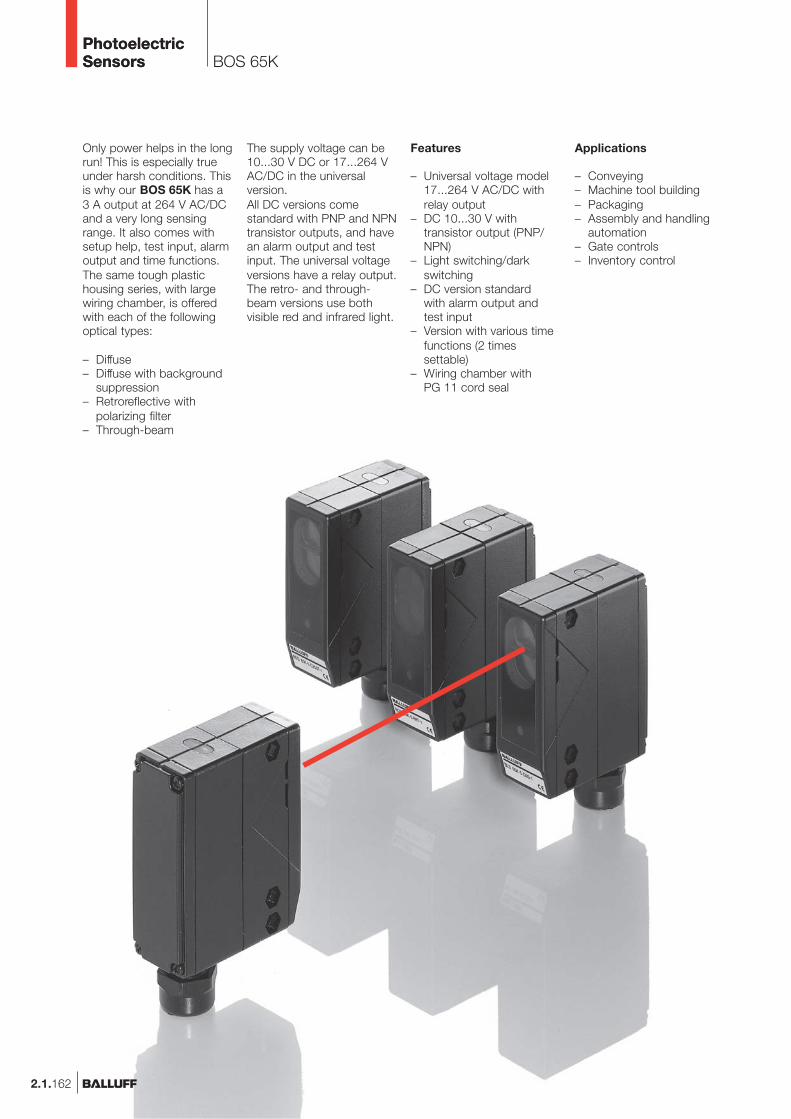
Features
– Universal voltage model17...264 V AC/DC withrelay output
– DC 10...30 V withtransistor output (PNP/NPN)
– Light switching/darkswitching
– DC version standardwith alarm output andtest input
– Version with various timefunctions (2 timessettable)
– Wiring chamber withPG 11 cord seal
Applications
– Conveying– Machine tool building– Packaging– Assembly and handling
automation– Gate controls– Inventory control
The supply voltage can be10...30 V DC or 17...264 VAC/DC in the universalversion.All DC versions comestandard with PNP and NPNtransistor outputs, and havean alarm output and testinput. The universal voltageversions have a relay output.The retro- and through-beam versions use bothvisible red and infrared light.
Only power helps in the longrun! This is especially trueunder harsh conditions. Thisis why our BOS 65K has a3 A output at 264 V AC/DCand a very long sensingrange. It also comes withsetup help, test input, alarmoutput and time functions.The same tough plastichousing series, with largewiring chamber, is offeredwith each of the followingoptical types:
– Diffuse– Diffuse with background
suppression– Retroreflective with
polarizing filter– Through-beam
2.1.162
BOS 65KPhotoelectricSensorsPhotoelectricSensors

BOS 65KProduct Overview
2.1.163
2.1
Photoelectricsensorsaccessoriespage 2.3.2 ...
2.3
Type
Diffusewith HGA
BOS 65K-5-M110T-1BOS 65K-5-M110T-2P-S4BOS 65K-1-M110T-1
DiffuseBOS 65K-5-C200T-1BOS 65K-5-C200T-2P-S4BOS 65K-1-C200T-1
RetroreflectiveBOS 65K-5-B8T-1BOS 65K-5-B8T-2P-S4BOS 65K-1-B8T-1
Through-beamBLE 65K-5-F50T-1BLE 65K-5-F50T-2P-S4BLE 65K-1-F50T-1
BLS 65K-5-G50-1BLS 65K-5-G50-2-S4BLS 65K-1-G50-1
OutputLighttype
Sensingdistance/range
0.2...1.1 m0.2...1.1 m0.2...1.1 m
0.05...2 m0.05...2 m0.05...2 m
0.3...8 m0.3...8 m0.3...8 m
0...50 m0...50 m0...50 m
0...50 m0...50 m0...50 m
Connec-tion
500 Hz500 Hz10 Hz
500 Hz500 Hz10 Hz
500 Hz500 Hz10 Hz
500 Hz500 Hz10 Hz
Outputfunction
Page
2.1.1652.1.1652.1.165
2.1.1652.1.1652.1.165
2.1.1652.1.1652.1.165
2.1.1652.1.1652.1.165
2.1.1652.1.1652.1.165
Helpfunctions
Red
ligh
t
Infra
red
M12
con
nect
or, 4
-pin
Wiri
ng c
ham
ber
10...
30 V
DC
Pol
ariz
ing
filte
r
NP
N-T
rans
isto
r
PN
P-T
rans
isto
r
Ligh
t-on
Dar
k-on
Ala
rm o
utpu
t
UBSwitchingfrequency
Rel
ay
17...
264
V A
C
Test
inpu
t
www.balluff.com
Connectors ...page 5.2 ...
5
PhotoelectricSensorsPhotoelectricSensors

2.1.164
Diffuse with background suppression maximum sensing distanceDiffuse maximum sensing distanceRetroreflective maximum rangeThrough-beam maximum range
DiffusePNP/NPN 0.2...1.1 m HGA, time function
0.05...2 m Time functionRelay 0.2...1.1 m HGA, time function
0.05...2 m Time functionRetroreflectivePNP/NPN 0.3...8 m Polarizing filter, red light, time functionRelay 0.3...8 m Polarizing filter, red light, time functionThrough-beamPNP/NPN 50 m Receiver, time function
50 m EmitterRelay 50 m Receiver, time function
50 m EmitterElectrical dataSupply voltage UB
No-load supply current I0 max.Switching outputOutput currentSwitching typeVoltage drop Ud at IeAlarm outputSettingsHelp functionIndicatorsPower-on indicatorOutput function indicatorStability indicatorTime dataResponse timeSwitching frequency fTime functionMechanical dataDimensionsConnectionmax. conductor cross-sectionHousing materialOptical surfaceWeightAmbient dataDegree of protection per IEC 60529Polarity reversal protectedShort circuit protectedAmbient temperature range Ta
Ambient light rejection
Diffuse values referenced to Kodak gray card 90% Reflexion.Retroreflective values referenced to R1 reflector.
Wiring diagrams, characteristics and accessories see page 2.1.166 and 2.1.167.
BOS 65KPhotoelectricSensorsPhotoelectricSensors

2.1.165
0.2...1.1 m0.05...2 m0.3...8 m0...50 m
BOS 65K-1-M110T-1BOS 65K-1-C200T-1
BOS 65K-1-B8T-1
BLE 65K-1-F50T-1BLS 65K-1-G50-1
17...264 V AC/DC
Relay 3A, 250 V AC/24 V DC
Light and dark (reversible)0 V
Potentiometer 270°
LED green (only for BLS)LED red
LED green
20 ms10 Hz
selectable 0.02…12 sec.
72.5×85×32 mmWiring chamber
0.75 mm2
PCPMMA160 g
IP 67yesno
–20...+55 °C3 kLux
0.2...1.1 m0.05...2 m0.3...8 m0...50 m
BOS 65K-5-M110T-2P-S4BOS 65K-5-C200T-2P-S4
BOS 65K-5-B8T-2P-S4
BLE 65K-5-F50T-2P-S4BLS 65K-5-G50-2-S4
10...30 V DC≤ 40 mA
PNP-Transistor200 mA
Light and dark (reversible)≤ 1.5 V
PNP-Transistor, 200 mAPotentiometer 270°Test input (for BLS)
LED green (only for BLS)LED red
LED green
1 ms500 Hz
selectable 0.02…12 sec.
72.5×85×32 mmM12 connector, 4-pin
PCPMMA180 g
IP 67yesyes
–20...+55 °C3 kLux
0.2...1.1 m0.05...2 m0.3...8 m0...50 m
BOS 65K-5-M110T-1BOS 65K-5-C200T-1
BOS 65K-5-B8T-1
BLE 65K-5-F50T-1BLS 65K-5-G50-1
10...30 V DC�
≤ 40 mAPNP and NPN Transistor
200 mALight and dark (reversible)
≤ 2 VPNP-Transistor, 200 mA
Potentiometer 270°Test input (except BLE)
LED green (only for BLS)LED red
LED green
1 ms500 Hz
selectable 0.02…12 sec.
72.5×85×32 mmWiring chamber
0.75 mm2
PCPMMA160 g
IP 67yesyes
–20...+55 °C3 kLux
BOS 65KSensing distance 1.1 m, 2 mRange 8 m, 50 m
2.1
Photoelectricsensorsaccessoriespage 2.3.2 ...
2.3
Connector orientation
www.balluff.com
Connectors ...page 5.2 ...
5
PhotoelectricSensorsPhotoelectricSensors

2.1.166
BOS 65KFunction diagramsConnection
Access to theoperating elementsby removing thecover (rear).
Diffuse BOS 65K-.-C200T-...
Through-beam BLE/BLS 65K-...
Retroreflective with polarizing filter BOS 65K-.-B8T-...
Emitter/Receiver
Kodak gray card90 % ReflexionKodak gray card
18 % Reflexion
Sensing distance measured with side approach of Kodak gray card.
For the through-beam the maximum possible offsetbetween emitter and receiver is measured.
Range measured using side approach with reflector.
ReflectorBOS R-1
Kodak gray card9 % Reflexion
ReflectorBOS R-10
Wiring diagrams
DC, screw terminals DC, screw terminals
AC, screw terminals AC, screw terminals
DC, connector DC, connector
DC, screw terminals
PhotoelectricSensorsPhotoelectricSensors

Mounting bracketBOS 65-HW-1
ConnectorBKS-_ 19/BKS-_ 20
Recommended accessoriesplease order separately
ReflectorBOS R-1
Alarm output for receiver,diffuse and retroreflective(DC)
The alarm output (PNP200 ma) for DC versionsgenerates a warning signalfor malfunctions due to
Test input for emitter,diffuse and retroreflective(DC)
The test input interrupts thelight pulses from the emitterand thereby allows it to betested for function.When using the test inputthe input must be set to10...30 V.The output must changeevery time there is 10...30 VDC on the test input.
Switchingthreshold
Stability(green LED)
Alarm
stable
unstable
stable
contamination or mechanicalmaladjustment.The alarm output is activatedif the signal received remainsin the alarm range for atleast 3 s.
Contamination ormaladjustment on the opticalaxis causes the emittersignal to reach the receiveronly weakly, if at all.Therefore the output will notchange even though the testinput is activated. The testfunction provides a remotecheck of the through-beamtype and serves as apreventive system check.
Programmable time functions
OutputLight-on
Switchsetting
Light
OutputDark-on
Light-onDark-on
2.1.167
BOS 65KDefinitionsAccessories
2.1
Photoelectricsensorsaccessoriespage 2.3.2 ...
2.3
Green stability display
The “threshold energy”,which results in a signalchange on output, is definedas 100 %.The switching state is con-sidered stable when theinput energy exceeds or fallsbelow the “threshold energy”by 30 %. The green LEDilluminates.
The “safe” range is thereforereached when– the input signal exceeds
at least 130% of thethreshold energy
– the input signal fallsbelow at least 70 % ofthe threshold energy.
Output(red LED)
Dar
k-on
Ligh
t-on
stable
unstable
stable
Switchingthreshold
Stability(green LED)
www.balluff.com
Connectors ...page 5.2 ...
5
PhotoelectricSensorsPhotoelectricSensors

2.1.96
BOS Q08M
Diffuse, Retroreflective,Through-beam Receiver
Wiring diagrams
Through-beam emitter
Miniaturization in the Balluffline continues at full pace.The new Opto-mini.sBOS Q08M sensors standout with their ease ofhandling and fixed sensingdistances and ranges.
The sensor family includesdiffuse types in block stylehousing with 8 mm sidelength, retroreflective andthrough-beam types.
Recommendedaccessoriesplease order separately
ConnectorBKS-_ 48/BKS-_ 49
ReflectorBOS R-9
These small photoelectricsensors open up possibilitiesin high-dynamic applicationssuch as on robotgripper arms. Here is wherecomponents with the lightestweight, a small footprint andyet the greatest switchingprecision are demanded.
PhotoelectricSensors

BOS Q08MProduct Overview
2.1.97
2.1
Photoelectricsensorsaccessoriespage 2.3.2 ...
2.3
Type
DiffuseBOS Q08M-PS-RD10-S49BOS Q08M-PO-RD10-S49BOS Q08M-PS-RD10-03BOS Q08M-PO-RD10-03
RetroreflectiveBOS Q08M-PS-PR10-S49BOS Q08M-PO-PR10-S49BOS Q08M-PS-PR10-03BOS Q08M-PO-PR10-03
Through-beamBOS Q08M-PS-RE10-S49BOS Q08M-PO-RE10-S49BOS Q08M-PS-RE10-03BOS Q08M-PO-RE10-03
BOS Q08M-X-RS10-S49BOS Q08M-X-RS10-03
OutputLighttype
Sensingdistance/range
0...55 mm0...55 mm0...55 mm0...55 mm
25...550 mm25...550 mm25...550 mm25...550 mm
0...1.1 m0...1.1 m0...1.1 m0...1.1 m
0...1.1 m0...1.1 m
Connec-tion
500 Hz500 Hz500 Hz500 Hz
500 Hz500 Hz500 Hz500 Hz
500 Hz500 Hz500 Hz500 Hz
Outputfunction
Page
2.1.982.1.982.1.982.1.98
2.1.982.1.982.1.992.1.99
2.1.992.1.992.1.992.1.99
2.1.992.1.99
Specialfeatures
Red
ligh
t
Infra
red
M8
conn
ecto
r, 3-
pin
Cab
le, 3
m
10...
30 V
DC
Pol
ariz
ing
filte
r
NP
N-T
rans
isto
r
PN
P-T
rans
isto
r
Ligh
t-on
Dar
k-on
UBSwitchingfrequency
mini.s
www.balluff.com
Connectors ...page 5.2 ...
5
PhotoelectricSensors

2.1.98
BOS Q08MRange 55 mm, 550 mm
25...550 mm
BOS Q08M-PS-PR10-S49BOS Q08M-PO-PR10-S49
10...30 V DC10 %
≤ 20 mAPNP-Transistor
100 mALight- or dark-on
≤ 2 Vfixed
25...500 mmLED, red light
640 nm
LED red
1 ms500 Hz
8×59×8 mmM8 connector, 3-pin
Nickel plated Gd-ZnPMMA13 g
IP 67yesyes
–10...+60 °CEN 60947-5-2
0...55 mm
BOS Q08M-PS-RD10-03BOS Q08M-PO-RD10-03
10...30 V DC10 %
≤ 20 mAPNP-Transistor
100 mALight- or dark-on
≤ 2 Vfixed
0...50 mmLED, red light
640 nm
LED red
1 ms500 Hz
8×44×8 mm3 m Cable PUR
3×0.14 mm²Nickel plated Gd-Zn
PMMA47 g
IP 67yesyes
–10...+60 °CEN 60947-5-2
0...55 mm
BOS Q08M-PS-RD10-S49BOS Q08M-PO-RD10-S49
10...30 V DC10 %
≤ 20 mAPNP-Transistor
100 mALight- or dark-on
≤ 2 Vfixed
0...50 mmLED, red light
640 nm
LED red
1 ms500 Hz
8×59×8 mmM8 connector, 3-pin
Nickel plated Gd-ZnPMMA13 g
IP 67yesyes
–10...+60 °CEN 60947-5-2
Diffuse maximum sensing distanceRetroreflective maximum rangeThrough-beam maximum range
DiffusePNP, NO 55 mmPNP, NC 55 mmRetroreflectivePNP, NO 25...550 mm Polarizing filterPNP, NC 25...550 mm Polarizing filterThrough-beamPNP, NO 1.1 m ReceiverPNP, NC 1.1 m Receiver
1.1 m EmitterElectrical dataSupply voltage UB
RippleNo-load supply current I0 max.Switching outputOutput currentSwitching typeVoltage drop Ud at IeSettingsOptical dataRecommended sensing distance/rangeEmitter, light typeWavelengthIndicatorsOutput function indicatorTime dataResponse timeSwitching frequency fMechanical dataDimensionsConnectionNo. of wires × cross-sectionHousing materialOptical surfaceWeightAmbient dataDegree of protection per IEC 60529Polarity reversal protectedShort circuit protectedAmbient temperature range Ta
Ambient light rejection per
Diffuse values referenced to Kodak gray card 90% Reflexion.Retroreflective values referenced to R9 reflector.
Connector orientation
PhotoelectricSensors

BOS Q08MRange 550 mm, 1.1 m
0...1.1 m
BOS Q08M-PS-RE10-03BOS Q08M-PO-RE10-03
10...30 V DC10 %
≤ 15 mAPNP-Transistor
100 mALight- or dark-on
≤ 2 Vfixed
0...1 m
LED red
1 ms500 Hz
8×44×8 mm3 m Cable PUR
3×0.14 mm²Nickel plated Gd-Zn
PMMA47 g
IP 67yesyes
–10...+60 °CEN 60947-5-2
0...1.1 m
BOS Q08M-X-RS10-03
10...30 V DC10 %
≤ 15 mA
fixed
0...1 mLED, red light
640 nm
8×44×8 mm3 m Cable PUR
2×0.14 mm²Nickel plated Gd-Zn
PMMA47 g
IP 67yesyes
–10...+60 °CEN 60947-5-2
0...1.1 m
BOS Q08M-PS-RE10-S49BOS Q08M-PO-RE10-S49
10...30 V DC10 %
≤ 15 mAPNP-Transistor
100 mALight- or dark-on
≤ 2 Vfixed
0...1 m
LED red
1 ms500 Hz
8×59×8 mmM8 connector, 3-pin
Nickel plated Gd-ZnPMMA13 g
IP 67yesyes
–10...+60 °CEN 60947-5-2
0...1.1 m
BOS Q08M-X-RS10-S49
10...30 V DC10 %
≤ 15 mA
fixed
0...1 mLED, red light
640 nm
8×59×8 mmM8 connector, 3-pin
Nickel plated Gd-ZnPMMA13 g
IP 67yesyes
–10...+60 °CEN 60947-5-2
25...550 mm
BOS Q08M-PS-PR10-03BOS Q08M-PO-PR10-03
10...30 V DC10 %
≤ 20 mAPNP-Transistor
100 mALight- or dark-on
≤ 2 Vfixed
25...500 mmLED, red light
640 nm
LED red
1 ms500 Hz
8×44×8 mm3 m Cable PUR
3×0.14 mm²Nickel plated Gd-Zn
PMMA47 g
IP 67yesyes
–10...+60 °CEN 60947-5-2
2.1.99
Photoelectricsensorsaccessoriespage 2.3.2 ...
2.1
2.3
mini.s
www.balluff.com
Connectors ...page 5.2 ...
5
PhotoelectricSensors