Embed Size (px)
Citation preview
Research Collection
Doctoral Thesis
Phononic quasicrystals
Author(s): Sutter-Widmer, Daniel
Publication Date: 2007
Permanent Link: https://doi.org/10.3929/ethz-a-005399971
Rights / License: In Copyright - Non-Commercial Use Permitted
This page was generated automatically upon download from the ETH Zurich Research Collection. For moreinformation please consult the Terms of use.
ETH Library
Diss. ETH Nr. 17174
Phononic Quasicrystals
A dissertation submitted to
ETH ZÜRICH
for the degree of
Doctor of Sciences
presented by
DANIEL SUTTER-WIDMER
Dipl. Ing. ETH
born 12.05.1978
citizen of Bretzwil (BL)
Accepted on the recommendation of
Prof. Dr. W. Steurer, examiner
Dr. U.G. Grimm, co-examiner
Dr. J.O. Vasseur, co-examiner
2007
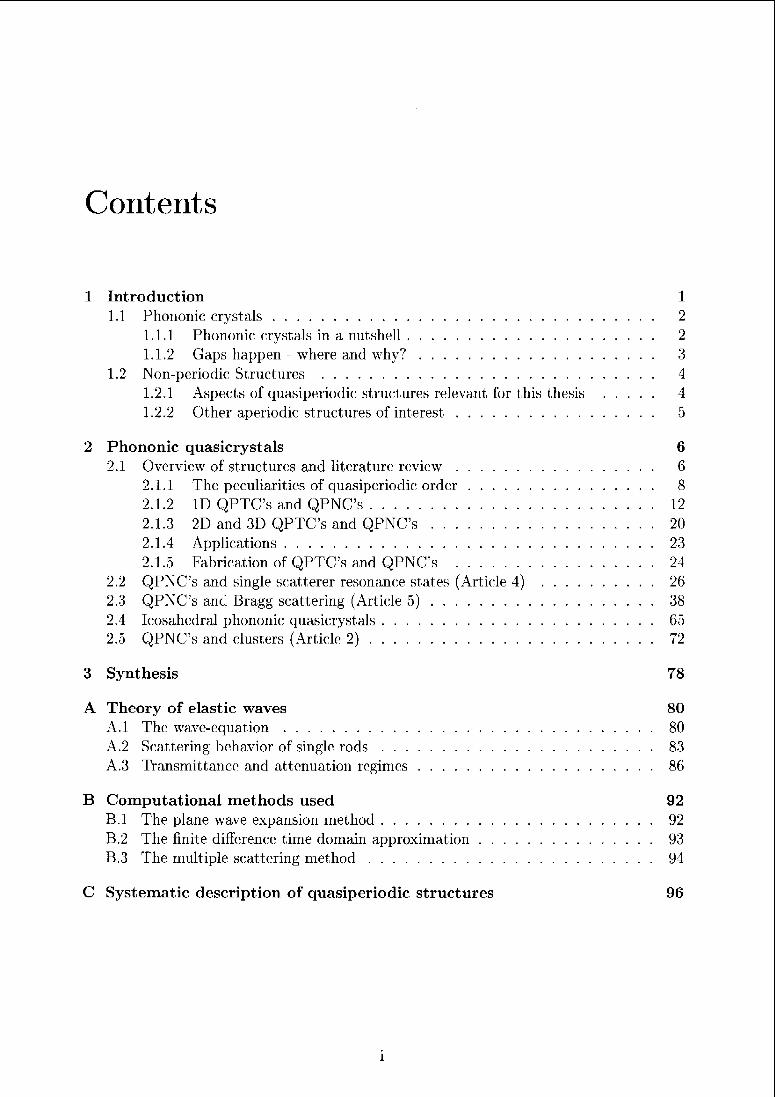
Contents
1 Introduction 1
1.1 Phononic crystals 2
1.1.1 Phononic crystals in a nutshell 2
1.1.2 Gaps happen - where and why? 3
1.2 Non-periodic Structures 4
1.2.1 Aspects of quasiperiodic structures relevant for this thesis 4
1.2.2 Other aperiodic structures of interest 5
2 Phononic quasicrystals 6
2.1 Overview of structures and literature review 6
2.1.1 The peculiarities of quasiperiodic order 8
2.1.2 ID QPTC's and QPNC's 12
2.1.3 2D and 3D QPTC's and QPNC's 20
2.1.4 Applications 23
2.1.5 Fabrication of QPTC's and QPNC's 24
2.2 QPNC's and single scatterer resonance states (Article 4) 26
2.3 QPNC's anc Bragg scattering (Article 5) 38
2.4 Icosahedral phononic quasicrystals 65
2.5 QPNC's and clusters (Article 2) 72
3 Synthesis 78
A Theory of elastic waves 80
A.l The wave-equation 80
A.2 Scattering behavior of single rods 83
A.3 Transmittance and attenuation regimes 86
B Computational methods used 92
B.l The plane wave expansion method 92
B.2 The finite difference time domain approximation 93
B.3 The multiple scattering method 94
C Systematic description of quasiperiodic structures 96
Seite Leer /
Blank leaf
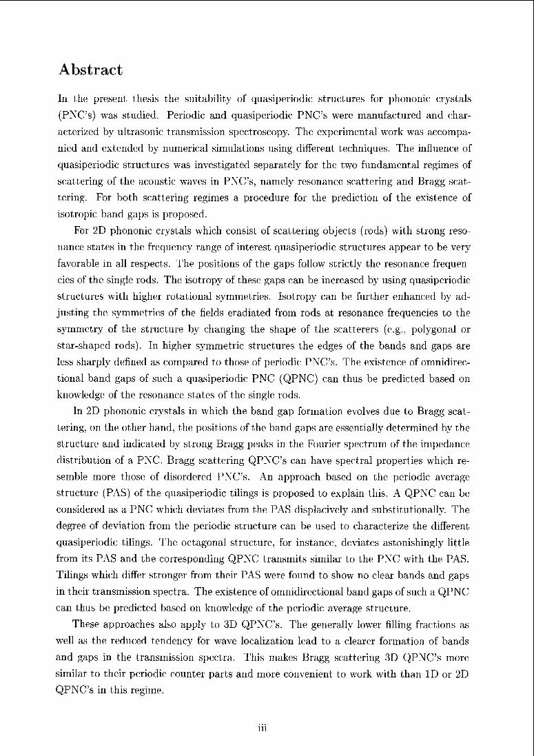
Abstract
In the present thesis the suitability of quasiperiodic structures for phononic crystals
(PNC's) was studied. Periodic and quasiperiodic PNC's were manufactured and char¬
acterized by ultrasonic transmission spectroscopy. The experimental work was accompa¬
nied and extended by numerical simulations using different techniques. The influence of
quasiperiodic structures was investigated separately for the two fundamental regimes of
scattering of the acoustic waves in PNC's, namely resonance scattering and Bragg scat¬
tering. For both scattering regimes a piocedure for the prediction of the existence of
isotropic band gaps is proposed.
For 2D phononic crystals which consist of scattering objects (rods) with strong reso¬
nance states in the frequency range of interest quasiperiodic structures appear to be very
favorable in all respects. The positions of the gaps follow strictly the resonance frequen¬
cies of the single rods. The isotropy of these gaps can be increased by using quasiperiodic
structures with higher rotational symmetries. Isotropy can be further enhanced by ad¬
justing the; symmetries of the fields eradiated from rods at resonance frequencies to the
symmetry of the structure by changing the shape of the scatterers (e.g., polygonal or
star-shaped rods). In higher symmetric structures the edges of the bands and gaps are
less sharply defined as compared to those of periodic PNC's. The existence of omnidirec¬
tional band gaps of such a quasiperiodic PNC (QPNC) can thus be predicted based on
knowledge; of the resonance states of the single rods.
In 2D phononic crystals in which the band gap formation evolves due to Bragg scat¬
tering, on the other hand, the positions of the band gaps are essentially determined by the
structure and indicated by strong Bragg peaks in the Fourier spectrum of the impedance
distribution of a PNC. Bragg scattering QPNC's can have spectral properties which re¬
semble more those of disordered PNC's. An approach based on the periodic average
structure (PAS) of the quasiperiodic tilings is proposed to explain this. A QPNC can be
considered as a PNC which deviates from the PAS displacively and substitutionally. The
degree of deviation from the periodic structure can be used to characterize the different
quasiperiodic tilings. The octagonal structure, for instance, deviates astonishingly little
from its PAS and the corresponding QPNC transmits similar to the PNC with the PAS.
Tilings which differ stronger from their PAS were found to show no clear bands and gaps
in their transmission spectra. The existence of omnidirectional band gaps of such a QPNC
can thus be predicted based on knowledge of the periodic average structure.
These approaches also apply to 3D QPNC's. The generally lower filling fractions as
well as the reduced tendency for wave localization lead to a clearer formation of bands
and gaps in the transmission spectra. This makes Bragg scattering 3D QPNC's more
similar to their periodic counter parts and more convenient to work with than ID or 2D
QPNC's in this regime.
m
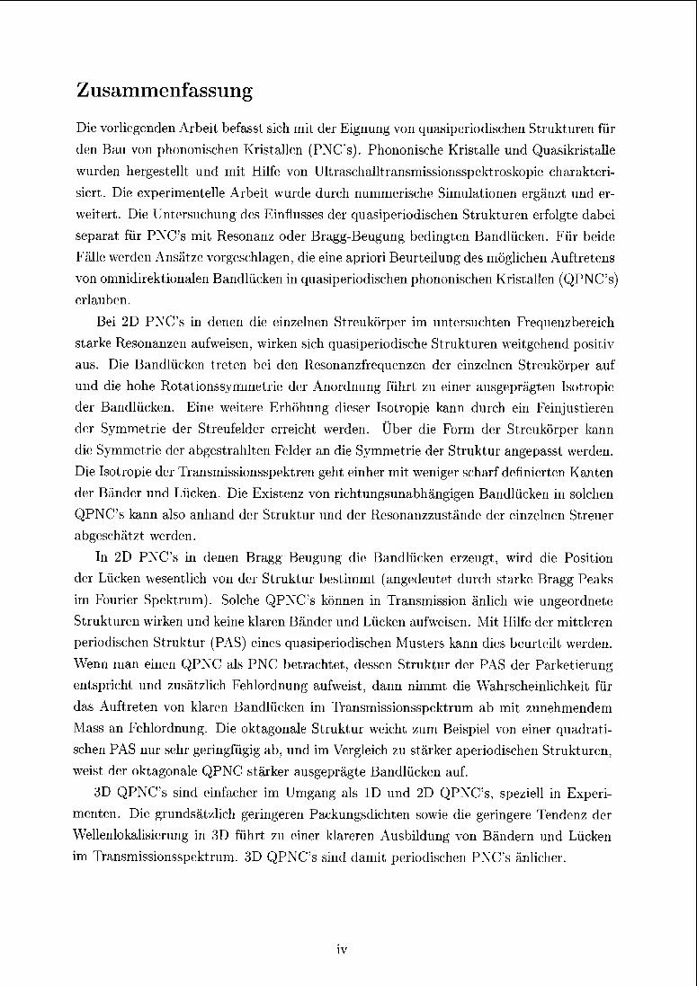
Zusammenfassung
Die vorliegenden Arbeit befa&st sich mit der Eignung von quasipcriodischen Strukturen für
den Bau von phononischen Kristallen (PNC's). Phononische Kristalle und Quasikristalle
wurden hergestellt und mit Hilfe von Ultraschalltran&mis&ionsspektroskopie charakteri¬
siert. Die experimentelle Albeit wurde durch nummerisehe Simulationen ergänzt und er¬
weitert. Die Untersuchung des Einflusses der quasiperiodischen Strukturen ei folgte dabei
separat für PNC's mit Resonanz oder Bragg-Beugung bedington Bandlücken. Für beide
Fälle werden Ansätze vorgeschlagen, die eine apriori Beurteilung des möglichen Auftretens
von omnidirektionalen Bandlücken in quasipcriodischen phononischen Kiistallon (QPNC's)erlauben.
Bei 2D PNC's in denen die einzelnen Streukörper im untersuchten Frequenzbereich
starke Resonanzen aufweisen, wirken sich quasipeiiodi&che Strukturen weitgehend positiv
aus. Die Bandlücken treten bei den Resonanzfrequenzen der einzelnen Streukörper auf
und die hohe Rotations&ymmetrio der Anordnung führt zu einer ausgeprägten lsotiopio
der Bandlücken. Eine weitere Erhöhung dieser Isotropie kann duich ein Feinju&tieren
der Symmetrie der Streufelder erreicht weiden. Über die Form der Streukörper kann
die Symmetrie der abgestrahlten Felder an die Symmetrie der Struktur angepasst weiden.
Die Isotropie der Transmissionsspektren geht einhei mit weniger scharf definierten Kanten
der Bänder und Lücken. Die Existenz von richtungsunabhängigen Bandlücken in solchen
QPNC's kann also anhand dei Struktur und der Resonanzzustände dei einzelnen Streuer
abgeschätzt weiden.
In 2D PNC's in denen Bragg Beugung die Bandlücken erzeugt, wird die Position
der Lücken wesentlich von dei Struktur bestimmt (angedeutet durch stark1 Bragg Peaks
im Fourier Spektrum). Solche QPNC's können in Transmission änlich wie ungeordnete
Strukturen wirken und keine klaren Bänder und Lücken aufweisen. Mit Hilfe der mittleren
peiiodischen Struktur (PAS) eines quasiperiodischen Musters kann dies beurteilt werden.
Wenn man einen QPNC als PNC betrachtet, dessen Struktur der PAS der Paiketierung
entspricht und zusätzlich Fehlordnung aufweist, dann nimmt die Wahrscheinlichkeit für
das Auftreten von klaien Bandlücken im Tran&missionsspektrum ab mit zunehmendem
Mass an Fehlordnung. Die oktagonale Struktur weicht zum Beispiel von einer quadrati¬
schen PAS nur sehr geringfügig ab, und im Vergleich zu stärker aperiodischen Strukturem,
weist der oktagonale QPNC stärker ausgeprägte Bandlücken auf.
3D QPNC's sind einfacher im Umgang als ID und 2D QPNC's, speziell in Experi¬
menten. Die grundsätzlich geringeren Packungsdichten sowie die geringere Tendenz der
Wellenlokalisierung in 3D führt zu einer klareren Ausbildung von Bändern und Lücken
im Transmissionsspektrum. 3D QPNC's sind damit periodischen PNC's änlichei.
IV
Abbreviations
nD n-dimensional
n-fold «-fold Patterson symiritery
tiling qiiasiperiodic arrangement of a set of tiles or the set of vertices of it
quasilattice vertices of a qiiasiperiodic tiling
PAS Periodic average structure of a qiiasiperiodic tiling
PNC phononic crystal
PTC photonic crystal
MC meta crystal
QPNC-n r?-fold phononic quasicrystal
QPTC-n n-fold photonic quasicrystal
QMC-n ra-fold qiiasiperiodic MC
APNC phononic crystal, the structure of which corresponds to the PAS of a QPNC
transmittance transmission coefficient (as a function of frequency)
u field of displacements of elastic waves
W, tp general wave-function
[d.i]
[i]
Literature references of the bibliography at the end of the thesis
Literature references of the bibliography at the end of an article
v
Chapter 1
Introduction
Phononic crystals are a very peculiar sort of matter. They are mimicking interaction of
electron waves with real crystals on altogether different scales with altogether different
waves and altogether different materials. And yet, a similarity persists. Quasicrystals on
the other hand, arc; a very peculiar sort of matter too. They are crystals and are yet none.
The intersection of these two types of matter, phononic quasicrystals, must therefore be
(peculiar)2. And that is what they are.
We start with an outline of this thesis work, which takes oik1 peculiarity at a time.
Outline of the thesis
• Phononic crystals
— Phononic crystals in a nutshell.
- Two prominent gap forming mechanisms: Bragg gaps vs. resonance gaps.
• Quasiperiodic and related structures
- Aspects of quasiperiodicity relevant for this thesis.
— Other aperiodic structures of interest.
• Phononic Quasicrystals (articles)
The main part of the report addresses 2D and 3D phononic quasicrystals. It starts
with a comprehensive review of the; literature including a host of illustrative exam¬
ples. Then the topic is tackled based on the distinction of the fundamental types of
phononic crystals, namely resonance- and Bragg-scattering based phononic crystals.
A section on cluster-based approaches and a summing up of all relevant results of
the thesis close the chapter.
• The appendices to this work provide a collection of illustrative explanations of cer¬
tain aspects of the theory of wave propagation as well as of quasiperiodic structures.
1
1.1 Phononic crystals
1.1.1 Phononic crystals in a nutshell
Historical notes
In 1987 Yablonovitchd-163 proposed a new class of materials. A periodic distribution of two
materials of different dielectric constants, nowadays known as photonic crystals (PTC's)
or photonic bandgap materials. Less noticed but at the same time, Lakhatikia et al.d-74
published an article on elastic wave propagation in a periodic array of elastic cylinders in
a different matrix material. Also a new class of materials, nowadays known as phononic
crystals (PNC's). Both names are directly referring to the analogy of these 'meta crystals'
and reals crystals, or more precisely, electronic crystals.
Motivations
Photons or phonons encounter a periodically varying environment just as do the electrons
in the potential of a crystal lattice. Interaction of waves with a periodic potential leads
to the formation of band gaps. The optical and acoustic bands and band gaps in the
dispersion relation can be engineered just as those of electrons. The ability of thereby
controlling the propagation of waves has attracted a lot of interest.
Beyond application driven research the analogy to real crystals promised also new ac¬
cess routes to quantum physical problems in solid state physics. The formal mathematical
equivalence between the solution of the wave functions of electrons in crystals (described
by Schrödinger's equation) and the1 acoustic wave functions in PNC's (described by the
elastic wave equation) is very fascinating. The essential difference is the type of boundary
conditions involved (i.e., Dirichlet conditions suit the electron and Neuman conditions
the acoustic interface problem'122). This astonishing fact still spurs, motivates and legiti¬
mates research of a highly complex topic like; electron wave; mechanics by means of simple
acoustic experiments or calculations on easily seven orders of magnitude larger length
scales.
After the rush of investigations of perfect periodic PTC's and PNC's today certain
key areas have proved most worthy for further research, which is pursued at high pace
(see J. Dowlings database'11 for a bibliography). In photonics such a focus certainly is
on optical device physics (i.e., waveguides, add-drop-filters, etc.). In acoustics among
the most promising applications thermal barrier materials'1'21 must be mentioned. In
both fields quasiperiodic structures have become very fashionable for reasons of both
potential applications as well as their fundamentally interesting spectral properties, which
are treated in detail in chapter 2. The subject is currently covered by about 300 papers
out of tin; approximately 8700 papers on photonic crystals and the 350 papers on phononic
crystals (as of March 2007). General introductions into phononic and photonic crystals
2
can be found in a review by Sigalas et al.d 1JUand the book Photonic Crystals. Towards
Nanoscale Photonic Devices*1 M2respectively.
1.1.2 Gaps happen - where and why?
In this subsection we want to introduce two fundamental mechanisms by which most types
of band gaps can be explained. This separation is important for understanding the diffei-
ent approaches to QPNC's in the articles constituting this thesis. The two mechanisms
are both well known in solid state physics and have been used to explain electronic band
structures from the very beginning. The Bragg gap picture is best imagined as analogue
to a nearly free electron approximation and the1 resonance gap picture is best viewed as a
tight-binding system.
Bragg gaps
Bragg scattering occurs, when the wave vector, k, of the incident wave points to the
boundaries of a Brillouin zone, Bragg scattering allows reflection of waves at certain
sets of scatterers (lattice planes). The interaction of incident and reflected waves (with
wave vectors k and —k = k + G = k) enforces a splitting of the dispersion relation for
acoustic waves in a PNC, which can be explained phenomenologically in many different
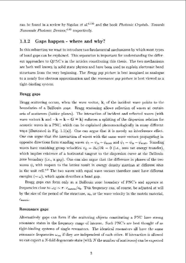
ways [illustiated in Fig. 1.1(a)]. One can argue that it is merely an interference effect.
One can argue that the inter action of waves with the same wave vectors propagating in
opposite directions form standing waves ip-\ = t^m + ^scatt and -01 = V;m _ V;scatt- Standing
waves have vanishing group velocities vq — du/dk — 0 (i.e., zero net energy transfer),which implies existence of a horizontal tangent to the dispersion curve at the Bnllouin
zone boundary (i.e., a gap). One can also argue that the difference in phases of the two
waves ipz with respect to the lattice result in energy density maxima at different sites
in the unit cell/18 The two waves with equal wave vectors therefore must have different
energies (~ o>), which again describes a band gap
Bragg gaps can form only at a Brillouin zone boundary of PNC's and appears at
frequencies close to ujg ~ tt rmatnx/a0. This fiequency can, of course, be adjusted at will
by the size of the period of the structure, a0, or the wave velocity in the matrix material,
^matrix
Resonance gaps
Alternatively gaps can form if the scatteiing objects constituting a PNC have strong
resonance states in the frequency range of interest. Such PNC's are best thought of as
tight-binding systems of single resonators. The identical resonators all have the same
resonance frequencies t^s if they are independent of each other. If interaction is allowed
we can expect a iV-fold degenerate state (with N the number of scatterers) can be expected
3
(a) jt/a0 2nla0 (b)
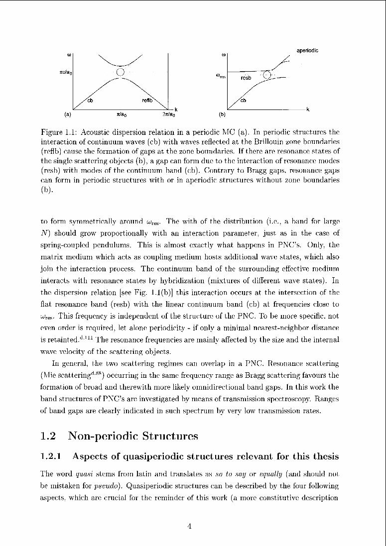
Figure 1.1: Acoustic dispersion relation in a periodic MC (a). In periodic structures the
interaction of continuum waves (cb) with waves reflected at the Brillouin zone boundaries
(reflb) cause the formation of gaps at the zone boundaries. If there are resonance states of
the single scattering objects (b), a gap can form due to the interaction of resonance modes
(resb) with modes of the continuum band (cb). Contrary to Bragg gaps, resonance gaps
can form in periodic structures with or in aperiodic structures without zone boundaries
(b).
to form symmetrically around u;res. The with of the distribution (i.e., a band for large
N) should grow proportionally with an interaction parameter, just as in the case of
spring-coupled pendulums. This is almost exactly what happens in PNC's. Only, the
matrix medium which acts as coupling medium hosts additional wave states, which also
join the interaction process. The continuum band of the surrounding effective medium
interacts with resonance states by hybridization (mixtures of different wave states). In
the dispersion relation [see Fig. 1.1(b)) this interaction occurs at the intersection of the
flat resonance band (resb) with the linear continuum band (cb) at frequencies close to
UV,. This frequency is independent of the structure; of the PNC. To be more specific, not
even order is required, let alone periodicity - if only a minimal nearest-neighbor distance
is retainted.dUl The resonance frequencies are mainly affected by the size and the internal
wave velocity of the scattering objects.
In general, the two scattering regimes can overlap in a PNC. Resonance scattering
(Mie scattering^'88) occurring in the same frequency range as Bragg scattering favours the
formation of broad and therewith more likely omnidirectional band gaps. In this work the
band structures of PNC's an; investigated by means of transmission spectroscopy. Ranges
of band gaps are clearly indicated in such spectrum by very low transmission rates.
1.2 Non-periodic Structures
1.2.1 Aspects of quasiperiodic structures relevant for this thesis
The word quasi stems from latin and translates as so to say or equally (and should not
be mistaken for pseudo). Quasiperiodic structures can be described by the four following
aspects, which are crucial for the reminder of this work (a more constitutive description
4
follows in appendix C):
• perfect short- and long-range order
• absence of a translational period (i.e. absence of a unit cell)
• a Fourier spectrum consisting of a dense set of singular 5-peaks
• Scaling symmetry of the Fourier spectrum.
The short-range order is asserted by the fact that the structures used to construct
PNC's correspond to the vertices of a tiling of the plane (or space) with at least two
different unit tiles. A finite set of nearest-neighbor distances follows from the finite set
of tiles. A finite set of nearest-neigbor distances is important for the chemistry of real
quasicrystals because it specifies the lengths of atomic bonds but it is equally important
for the interaction of scattered near-fields in phononic quasicrystals. The long-range order
allows coherent interaction of these scattered waves. This first aspect is in focus of an
approach to understanding phononic quasicrystals in Sec. 2.2.
The second aspect introduces the major difficulty. In order to calculate or measure the
physical properties of infinite quasiperiodic systems either a large finite section or the peri¬
odic repetition of a smaller section of the quasiperiodic system can be analyzed. With in¬
creasing size of the chosen sections the properties are assumed to converge towards the ones
of the infinite system. Thus, usually there are no exact solutions and existing computer
programs can be used only for approximations (with v ry few exceptions'1'67'dfi8, d109).The third point, in return, provides some help because it indicates that certain spatial
periods arc; important for the physical properties of the quasiperiodic system. This aspect
is dealt with in an approach to understanding phononic quasicrystals in Sec. 2.3. The
definition of crystals as well as quasicrystals also evolves via the Fourier space properties.
While crystals are defined by the IUCr as structures with an essentially discrete diffraction
spectrum, quasicrystals are crystals without a spatial periodicity.
1.2.2 Other aperiodic structures of interest
Other aperiodic structures which are interesting for this work differ from quasiperiodic
structures mainly in the Fourier spectrum.
If in quasiperiodic structure a degree of periodicity can be considered (due to the fact
that the Fourier spectrum consists purely of 5-peaks) then for less periodic structures
these peaks are getting sparser and sparser and continuous parts appear. Ultimately,
in critically periodic structures the 5-peaks have transformed into a singular continuous
spectrum. For instance, a structure that has a spectrum which lacks Bragg peaks is very
interesting because of the importance of Bragg peaks for the formation of band gaps.
5
Chapter 2
Phonemic quasicrystals
2.1 Overview of structures and literature review
The aim of this overview is to work out how the peculiarities of quasiperiodic order
affect the formation of band gaps in photonic and phononic crystals but also why these
structures can be interesting with regard to potential applications of band gap materials.
The overview is combined also with an overview of the literature on both quasiperiodic
phononic an photonic: crystals. The overview focuses mainly on ID aperiodic sequences
in which the relationship between the structural nature and its effect on the propagation
of waves can be most easily demonstrated. But, also certain 2D structures are considered
but their detailed discussion can be found in subsequent sections. Promising applications
and fabrication techniques are reviewed at the end of this section.
6
Introduction
The interesting property of phononic crystals, PNC's, and photonic crystals, PTC's, is
the band gap. Such band gaps can be best studied and also best exploited in applica¬
tions if their frequency range does not depend on the crystallographic direction of wave
propagation. To give an example, a waveguide can be realized in PNC's simply by a
row of missing rods. The waveguide can only be used to direct a wave along a curved
path if the surrounding crystal is impenetrable for the wave for all possible directions
the guide happens to take. Clearly, for most periodic structures such an isotropy is not
given. It may happen that in the frequency range of a band gap in direction o there
is the center of a strong band for direction fo.dJ/11 If the gaps do not overlap in the dif¬
ferent directions, then controlling the propagation of waves is difficult because there is
always a direction in which the wave can escape from confinement. This is exactly where;
quasiperiodic structures become; interesting. Quasiperiodic order is characterized by a
discrete Fourier spectrum with arbitrarily high rotational symmetry consisting purely of
Speaks, and this despite the lack of translational symmetry. The physical properties
of systems with quasiperiodic order (e.g., band gaps) can thus become highly isotropic.
Beyond isotropy of diffraction properties, quasiperiodic structures are interesting because
of their scattering activity on multiple scales as well as the special type of wave functions,
which are interesting from a point of view of fundamental physics.
But, what really is the difference between periodic and quasiperiodic order, and how
relevant is it for practical applications in such meta-crystals (MC's)? Basically, the un¬
derlying physics (i.e., the; scattering mechanisms discussed in Sec. 1.1.2) an; exactly the
same for QMC's and MC's. This is also true for potential applications as well as the
fabrication techniques. This, justifies to focus on the structural aspects of band gap engi¬
neering. One special point must thereby be considered at all times. MC's usually consist
only of hundreds to thousands of building units. In the comparison to real intermetallic
quasicrystals in which the number of atoms is larger by almost twenty orders of magnitude
the question arises, when are MC's large enough to exhibit typical physical characteristics
of quasiperiodic systems? Or in the light of future applications even more relevant may
be the question, when are MC's large enough to inherit those characteristics of quasiperi¬
odic structures, which an1 required for optimal performance. Especially the presence of
localized waves makes transport properties of finite quasiperiodic MC's prone to severely
depend on the size of the sample.
After the following summary of general aspects of quasiperiodic patterns, the structure
of this overview follows the dimensionality of the MC's. This is almost equivalent with a
chronological ordering due to the higher complexity of experimental as well as theoretical
approaches to 2D and 3D QMC's. For all dimensions, typical representatives are discussed.
7
2.1.1 The peculiarities of quasiperiodic order
Fourier spectrum
The Fourier spectrum (kinematic diffraction pattern), P(k) reveals best the; characteristics
of ordering types (see, for instance, Baaked11 or Axel and Gratiasd9). Generally, three
terms can contribute to the Fourier spectrum
F(k) = Ppp(k) + Psc(k) + PD,(k). (2.1)
The pure point part, Ppp(k), refers to the Bragg reflections, the absolute continuous
part, Pa[ (k), is a continuous function (diffuse scattering) and the singular continuous part,
Pgc(k), is somewhere in between. It is neither continuous nor does it have Bragg peaks.
It does have peaks but these are never isolated and for increasing resolution reveal more
and more detailed subpeak structures. The integrated diffraction intensity looks like a
Cantor function (see Janner'iq). The Fourier spectrum of random(ized) structures is abso¬
lute continuous but may show broadly-peaked diffuse scattering due to local correlations.
Infinite periodic structures have a pure point Fourier spectrum. The set of diffraction vec¬
tors, k, of the Bragg peaks of a dB structure form a Fourier (Z-) module of rank n = d.
Quasiperiodic structures, such as the Fibonacci sequence or the Penrose tiling, exhibit
a pure point spectrum as well, however, the rank of their Fourier module exceeds their
dimensionality, n > d (see appendix C). A Fourier module of infinite rank characterizes
almost periodic structures such as regular fractals like the Sierpinski gasket. The peaks
in spectra with n > d densely cover the plane (fill the space) and may already appear
singular continuous. An example case for a structure with a really singular continuous
spectrum is for instance; the Time-Morse sequence and for an absolute continuous Fourier
spectrum the Rudin-Shapiro sequence can be mentioned.'141
The nomenclature; of QCs is based on their experimentally accessible diffraction sym¬
metry. The point group of tin; diffraction pattern is always centrosymmetric and symmor-
phic (i.e. apart from translations, only point group operations act as generating symmetry
operations). Consequently, all 2D A^-fold tilings with odd N, exhibit Patterson symmetry
(2N)mm, and those with TV even, the symmetry Nrnrn. The 2D Penrose tiling, for in¬
stance, has Patterson symmetry 10mm although it exhibits locally 5-fold symmetry only.
In the following, we will use the notation QPTC-/V, QPNC-/V or simply QMC-N for
quasiperioidc heterostructures with A^-fold Patterson symmetry. If in the literature the
terms 5-, 7- or 9-fold symmetry are given, we use 10-, 14- and 18-fold symmetry instead.
Real space structure, Tilings and coverings
Quasiperiodic systems are often treated as intermediate between periodicity and random¬
ness. This intermediary stems from their spectral or their macroscopic physical properties.
It must not be mistaken for a structural aspect. Quasiperiodic structures are perfectly de-
8
terministic and long-range ordered as are periodic structures. The direction dependence of
some; physical properties of quasiperiodie systems may indeed be closer to that of random
systems than to that of perioidc systems. For instance, the elasticity tensor of icosahedral
quasicrystals has only two independent coefficients like it has in amorphous materials,
while cubic crystals have three. But again, real crystal structures are never truly random
structures as a point sets can be;. Real crystal structures need not to have a minimum
distance, for instance. Although an overlap of scattering objects of a MC could be ac¬
complished (for instance, if particles partially merge by sintering), this is not generally
interesting. Such a defect would rather be treated as a substitution of a certain scattering
object by a larger one. Random point sets do not generally fulfill the Delone condition,
which periodic and quasiperiodie point sets do. The Delone condition states that the
point distribution should be uniformly discrete (minimum distance; between points) and
relatively dense (maximum hole size) (see, for instance, BaakedU). Structures may, how¬
ever, be formed by random arrangements of a set of unit tiles or deviate randomly from
an ordered structure. Randomization destroys the correlations in a structure, which is
reflected directly in the Fourier spectrum.
While for periodic tilings (lattices) a single prototile suffices to cover the plane, for
quasiperiodie tilings at least two unit tiles are required. The regular Penrose tiling, for
instance, consists of two types of tiles, a skinny and a fat rhomb. One consequence of the
larger number of tiles is the increase of different possible vertex coordinations grows with
the number of unit tiles, which can be interesting for defect creation. If the unit tiles
are arranged in a (complex) periodic way, an approximant is formed. Quasiperiodicity
can be enforced by imposing matching rules that specifiy unambiguously how a certain
tile has to be joined by surrounding tiles. Alternativly, the set of unit tiles and the
corresponding matching-rules can be transformed into a unit cluster and corresponding
overlapping rules.dM In both descriptions a relaxation of the rule of connectivity permits
randomization and disorder.
A third possibility to construct a tiling is given by the higher-dimensional approach.d5rj
A quasiperiodie structure can be generated as intersection of a r?D hypercrystal, deco¬
rated with (n — d)D atomic surfaces (occupation domains) with the dD physical space (a
pedagogically more appealing description is given in appendix C). The dimension n of the
(embedding space, V, is determined by the rank of the Fourier module of the quasiperioidc
structure. The embedding space consists of the two orthogonal subspaces, the perpendic¬
ular space, V-1-, and the physical or parallel space V". The set of n basis vectors spanning
the nD lattice not commensurate with the V. Consequently, the physical space cuts the
hypercrystal irrationally, i.e. the cut hyperplane does not contain any nD lattice point
besides the origin (see Fig. C.l). If the hypercrystal is sheared parallel to the perpendic¬
ular space, additional lattice points fall into V" and the intersection results in a periodic
structure. Such a rational approximant is not equivalent to a patch punched out of a
9
quasiperiodic tiling.
The simplest way to generate a quasiperiodic tiling is by the generalized dual-gr'id
method*-17',U7
The periodic average structure (PAS)
The periodic average structure (PAS) of a quasiperiodic tiling can be obtained by oblique
projection of the nD hypercrystal onto parallel space.dAS' d137 The nD hyperlattice is
projected onto a simple periodic lattice (see Fig. C.2). The nodes of this lattice are deco¬
rated with the projections of the atomic surfaces. Equivalcntly, if the infinite quasiperiodic
structure is projected into one unit cell of its PAS, the vertices all fall into the projected
atomic surfaces leaving the rest of the cell empty.
In principle every pair of strong Bragg peaks defines a reciprocal PAS. The significance
of these infinitely many PASs is weighted by amplitudes of the Bragg peaks defining them.
The periodicity of the PAS allows to define a Brillouin zone (BZ) as usual. The Jones zone
(JZ) or pseudo-BZ used for aperiodic crystals, is spanned by the same Bragg peaks as is
the PAS only, the pseudo BZ does not form a periodically repeatable reciprocal unit cell
but has the symmetry of the diffraction pattern. In a crude approximation, a QMC can
be seen as perturbation of its PAS. The first strong Bragg reflection, which is common to
the quasiperiodic structure and its PAS, induces tin; first band gap equally to the QPNC
and the PNC with its PAS.d145 Beyond this, the PAS allows further characterisation of
a tiling with respect to its potential in QMC's as is discussed in Sec. 2.3. The concept of
the PAS can be meaningfully applied to all structures with a Fourier module.
Properties of quasiperiodic structures relevant for wave propagation
Waves in MC's encounter a spatially modulated impedance distribution and therefore
incur multiple diffraction and refraction. The resulting interference wave fields can either
be mobile and transport energy or become localized. These phenomena are quite well
understood already for periodic and disordered periodic MC's'1,125 (see appendix A.3 for
an introduction). As discussed already in the introductory section Sec. 1.1.2 the first
gap in the transmission spectrum of a QMC is often related to the first strong Bragg
reflection.'1'61'dl5G The symmetrically equivalent MC directions along which such band
gaps appear follow the diffraction symmetry. The1 higher the; rotational symmetry the
closer to a circle is the Brillouin-zone and the more overlapping are the band gaps in
the different directions. An reasonable overlap of gaps for all directions of transmission
is therefore achieved even when the gaps are narrow. Therewith constituent materials
can be used with lower impedance contrast than for the best MC's with crystallographic
symmetry. This is particularly important in the cases of self-organized colloidal MC's,
because usually only low impedance contrast can be achieved in such systems.'1135
10
What is the equivalent to propagating Bloch waves in QMC's? Despite the fact that
mathematically the Bloch/Floquet theorem does not hold for quasiperiodic structures the
observation of the Borrmann effect [i.e., anomalous (easy) transmission of X-rays through
a perfect crystal] in icosahedral Al-Mn-Pd quasicrystalsd13, dM indicates the existence of
Bloch-like waves. For anomalous transmission, a standing wave must exist with its nodes
at the planes of highest electron densities and for quasiperiodic structures these planes are
the lattice planes of the PAS.d H0 This is also true for QMC's, and we can assume that
we have propagating waves related to the respective PAS. The broader distribution of
averaged scattering densities of the PAS compared to that of the MC may be one reason
for the slower evolution of Bragg gaps in the transmission spectra of QMC's.
If suitable parameters are found for a QPNC system the scaling symmetry as well as the
self-similarity of the; diffraction pattern are both reflected in the transmission spectra and
the band structure. This is best achieved when the nature; of the scattering objects affect
band structure formation as little as possible (i.e., absence of single object resonances),
for instance, when the size of the scatterers is small with respect to the typical distances
of the structure.
Further typical for QMC's is the possible (co-)existence of extended and localized (or
confined) as we'll as critically localized modes. While in periodic structures all modes arc;
extended unless disorder is introduced, perfect quasiperiodic order seems to get along
well with localization. This fact is usually explained by the conflict of aperiodieity, which
drives for locali/ation, and self-similarity, which drives for extended wave functions.d'19 An
intermediate, weaker form of localization is reflected m the usually power law decaying,
critical wave functions. While this connection is intuitive, the nature of the wave functions
are strictly determined by the type of the spectrum and critical waves are so intrinsic to
systems with singular continuous spectra (see Kohomoto and SutherlanddG8 and references
therein).
Similarly to all this, high-symmetry patches (clusters) with a high local scatterer
density are generally assigned the prominent role to act as centers hosting localized reso¬
nance modes (coupled single object resonances). Due to the repetitive properties of some
quasiperiodic structures, such clusters will occur everywhere in the structure, again and
again. For instance, in case of the regular Penrose tiling any patch with diameter d will be
found again within a distance of 2d. Overlapping of wave functions localized at adjacent
and not too distant clusters then allows exchange of energy and therewith propagation.
Consequently, if these clusters are not distributed sparsely (e.g., singular tilings with one
high-symmety cluster in the center) the modes are trapped. This has been studied for
QPTC-8, -10, and -12 by Wang and co-workers.d-159
11
Defects and system sizes
Due to the larger number of local environments in quasiperiodic as compared to periodic-
structures many different point defects can be formed and therewith many different defect
states. Many of the strange properties of quasiperiodic and other deterministic aperiodic
structures only develop in infinite system sizes. Even the plain Fourier spectrum of a
system of experimentally or computationally realizable sizes may look rather unspectac¬
ular. In QMC's, the number of scattering objects was as large; as a few hundreds to
thousand. Whether or not much larger structures would be closer to ideal case depends
on their experimentally achievable perfection (degree of long-range order). It determines
its structural correlation or coherence length, which should best be at least of the order
of the coherence length of the probing waves used.
2.1.2 ID QPTC's and QPNC's
The effect that the special types of order have on the propagation of waves in MC's are
illustrated by ID substitutional sequences, which represent the different ordering types.
The quasiperiodic Fibonacci sequence is thereby compared to the critically periodic Thue-
Morse and the almost periodic period doubling sequence. The ID substitutional sequences
used are words defined by a finite alphabet (A, B) a seed and a substitution rule a, which
can be applied to a word. Multiple application of a. wn — <Jn{Ä) leads to longer and
longer sequences. A overview of the properties of QPTC's based on such sequences is
given by Albuquerque and Cottam.'16
All PNC's treated in this overview consist of arrays of thin epoxy sheets in water
separated by two distances A and B which are chosen as 1 and r. The thickness, d, of
the sheets is oik1 tenth of A.
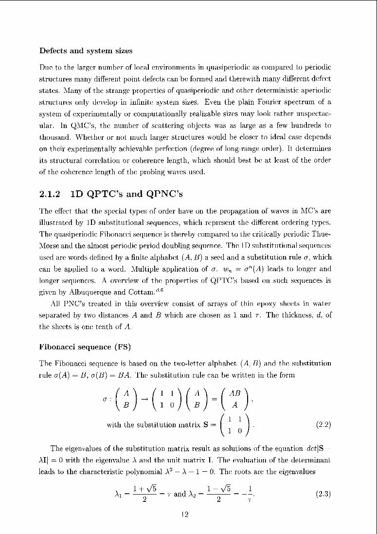
Fibonacci sequence (FS)
The Fibonacci sequence is based on the two-letter alphabet (J4, B) and the substitution
rule a (A) = B7 o(B) — BA. The substitution rule can be written in the form
with the substitution matrix S =. (2.2)
The eigenvalues of the substitution matrix result as solutions of the equation det\S —
AI| — 0 with the eigenvalue A and the unit matrix I. The evaluation of the determinant
leads to the characteristic polynomial A2 — A — 1 = 0. Tin; roots are the eigenvalues
Ai = —-— = t and A2 = —-— = —. (2.3)I It
12
If the characteristic polynomial has integer coefficients then the eigenvalue's aie always
algebraic numbers (Pisot numbers) and the sequence is quasiperiodic. One eigenvalue
is always larger than one while the modulus of its conjugate is smaller than one,d83
Ai > 1,|A2| < 1.
The structure grows as A -> AB -v ABA -> ABAAB -> ABAABABA etc.. The
length of the sequence at the iteration n is Fn+1 + Fn. The ration of the occurrence1 of
the two segments is Fn+1/Fn and conveiges towards r. If we assign intervals of lengths 1
and r to A and B then the resulting ID structure s(r) is invariant under scaling by r",
s(rr) = s(r). And so is the Fourier spectrum. The Fouiier module of the FS is of rank 2
and its diffraction pattern is a pure point spectrum (i.e., Bragg leflections only). The FS
has a periodic aveiage structuie with a period «pas = (3 — r)A
Only one year after the discovery of quasicrystals in 1984d 122 Merlin et al.d 8Tinves¬
tigated a FS based GaAs/AlAs heterostructure by Raman scattering. The theoretical
analysis of this system followed in 1987.di49 They found gaps in the density of states
of longitudinal-acoustic phonons propagating perpendicular to the multilayer structure.
Thus, in principle the fiist gap in a ID QPNC was found already two years befoie the
invention of band gap materials.
The early works on FS-QMC's clearly focused on the fundamental aspects and impli¬
cations of quasiperiodicity. First of all, it was demonstrated that band gaps can form in
non-periodic structures [see also Fig. 2.1(c)]. Kohomoto et al.d>db* further confirmed
the self-similarity and the critical nature of the wave functions in FS-QMC's in analogy to
theii previous woiiva on quasipeiiodic election systems (see also Hattori et o/.d48). An il¬
lustrative way to directly visualize the different propagation of waves in quasiperiodic and
periodic structures is to combine them in a hybrid structure. Montalban et a/.d9i have
shown how some of the waves localize in the quasiperiodic section of the structure. They
also pointed out that the bandgaps of FS-QPTC are very robust against imperfections
occurring in experimental realizations. The size-dependence of the transmission spectra
and band structure was explored by Kaliteevski and co-workers.d 62They showed, that
despite the fact that the main gaps of the band structure become cleaily visible already
for small generations of the sequence (see also Fig. 2.8), the exponential decay of the
waves inside these gaps is much weaker than in periodic structures. Additionally, in this
work a method to solving the wave equation by moans of an expansion of the fields and
the dielectric constant distribution in terms of stiong Fouriei coefficients in the diffrac¬
tion pattern of the FS. This connection appears veiy reasonable when the tiansmission
curve of FS-QPNC's are compared to the Fourier transform of its impedance distribu¬
tion (see Fig. 2.1). For every strong Bragg reflection, there is a conesponding gap And
also the fine stiucture of the tiansmission spectrum are correlated with diffraction peaks.
Furthermore1, the diffraction pattern of the FS is not only self-similar but also invariant
under scaling with factor r. The same applies to the transmission curve [Fig. 2.1(c)].
13
S (a)
|(b)
fa„„ /c
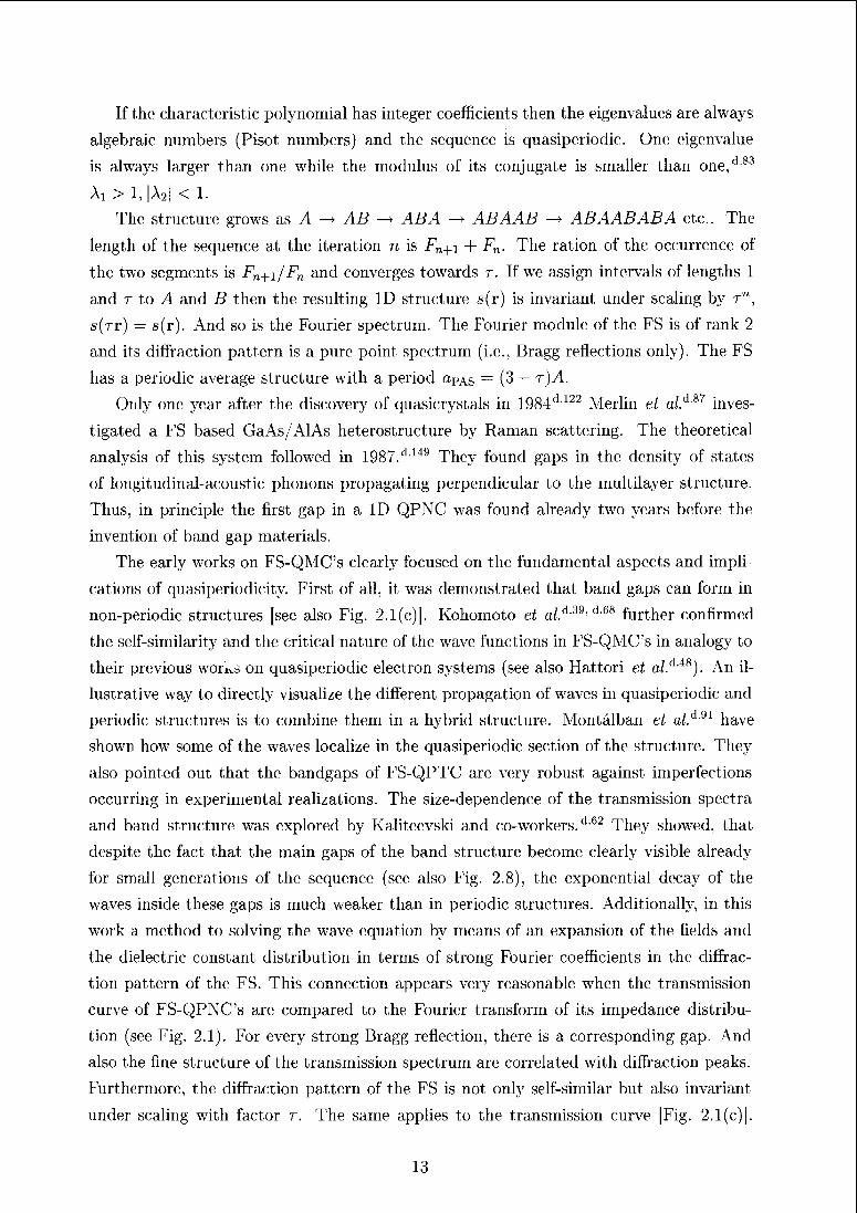
Figure; 2.1: In (a) the impedance variation of the w8 Fibonacci QPNC is shown (55
sheets) and its Fourier transform in (b). The thickness ratio of B and A blocks is 1/r.The transmission spectrum and superposed its r-scaled equivalent is shown in (c). The
inset in (c) indicates the self-similarity of the gap positions.
In the light of this analogy the fact that no connected band of strong transmission can
survive if larger and larger FS with more and more diffraction peaks are considered seems
only conclusive. The analogy of Fourier and transmission spectrum may not be very well
visible in certain realizations of FS-QMC's. The influence of the nature of the scattering
unit is best reduced by using thin interface films separating blocks of a single material
but with two different thicknesses which arc; both large with respect to the interface layer
thickness. Investigations of FS-QPTC's did not only aim for answers to fundamental
physical issues, they also proofed, that quasiperiodic structures can be well used for ap¬
plications of MC's. It was already indicated by Merlin et al.d 87 that FS-QMC's may have;
gaps which an; independent of the angle of incidence in an extended range. Indeed, a
proper design was found for an omnidirectional reflector for electromagnetic waves in the
infrared region. Lusk and Placido084 have measured an angle-independent reflectivity of
99.5 % in a FS-QPTC consisting of only 13 layers of Si02 and Si. The possibilities to
create high transmission modes in ranges of the band gaps also in aperiodic layered struc¬
tures was demonstrated by Peng and co-workers.di03 As a prerequisite for the existence
of such modes they mention the mirror symmetry of a stacking sequence. In Fibonacci
sequences mirror symmetry can be easily obtained by removal of the first two letters of
the sequence.d r'2
Typical features of a Fibonacci QPNC are shown in Fig. 2.1. The Fourier transform
of the finite ID w& structure consisting of 55 A and B blocks features already a large
number of Bragg peaks. Each of these peaks clearly induces a gap in the transmission
spectrum. The; depth as we1!! as the width of the gaps are clearly following the intensity
14
of the Bragg peaks [Fig. 2.1(c)J. The main gaps develop already in very short sequences
(i.e., the second or third generation) and do not change significantly for larger sequences.
In the ranges of the bands in between though, an increasing degree of fine structure of
gaps and peaks evolves. The positions of gaps is invariant under a scaling operation with
factor t just as is the Fourier spectrum. Also the transmission bands (which can be
determined in spectra of short sequences) show a scaling symmetry with respect to their
center as well as self similarity at any frequency. For an eighth generation sequence the
first gaps appear at foyAS/c ~ 0.2, well below the first gap induced by the Bragg peak of
the reciprocal average structure.
Thue-Morse sequence (TMS)
The (Prouhet-)Thue-Morse sequence is based on the two-letter alphabet (A,B) and the
substitution rule o~(A) = AB, o~(B) — BA. The substitution rule can be written in the
form
with the substitution matrix S —
The eigenvalues of the substitution matrix, A: = 2 and A2 — 0 can be obtained
from the characteristic polynomial A2 — 2A = 0. Despite the fact, that they are Pisot
numbers, the Fourier spectrum of the Thue-Morse sequence is singular continuous and
the sequence! is not quasiperiodic. At first glance the sequence appears to be even more
periodic than the FS. Partitioning of the sequence into AB and BA blocks results in a
periodic substructure with period A + B. Only due to the special order of the sequence
the Bragg peaks associated with the reciprocal average structure vanish for large enough
sequences as do all other Bragg peaks.d"51 The sequence grows as j4 -+ AB —» ABBA
—> ABBABAAB etc.. The length of the sequence at the iteration n is 2". The frequencies
of the letters A, B in the sequence are equal.
The facts that the Fourier spectrum of this sequence lacks Bragg peaks and that the
formation of band gaps is closely connected to Bragg scattering have spurred a surprisingly
large1 number of studies on PTC's with TMS structure1. In a very detailed theoretical
study erf the optical transmissiem as functiem e>f e>f the layer number Riklund and Severin
have shown that the transmission spectrum differs considerably from those of FS based
QPTC's in that there are certain ranges which remain almost unfragmented also for very
large numbers of layers/1110 In FS-QMC's, on the other hand, all bands are split by large
numbers of narrow gaps for sufficiently large systems [e,e)mparei Figs. 2.1(c) and 2.2(c)]. In
the; same frequene;y ranges there are almost no Bragg peaks in the Fourier spectrum. This
could be an onset of vanishing of Bragg peaks as is anticipated for the infinite sequence
(2.4)
15
S (a)
a„, /r
(b)
kUAhLk*.... ..^UjMJtjLLuJL^^JiiL
faoas /c
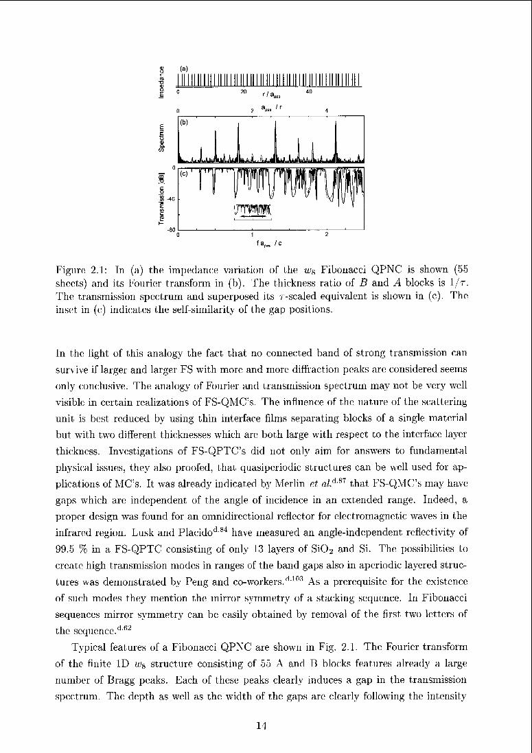
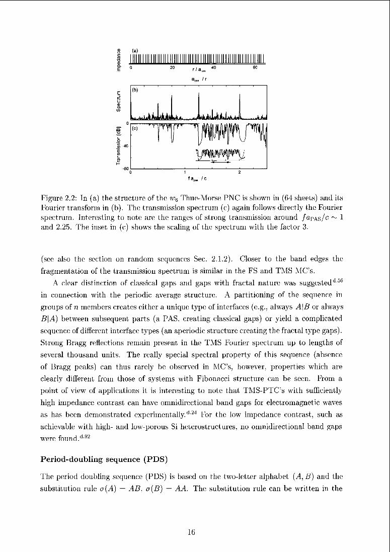
Figure 2.2: In (a) the structure of the w6 Thue-Morse PNC is shown in (64 sheets) and its
Fourier transform in (b). The transmission spectrum (c) again follows directly the Fourier
spectrum. Interesting to note are the ranges of strong transmission around /apAs/<" ~ 1
and 2.25. The inset in (c) shows the scaling of the spectrum with the factor 3.
(see also the section on random sequences Sec. 2.1.2). Closer to the band edges the
fragmentation of the transmission spectrum is similar in the FS and TMS MC's.
A clear distinction of classical gaps and gaps with fractal nature was suggestedd5&
in connection with the periodic average structure. A partitioning of the sequence in
groups of n members creates either a unique type of interfaces (e.g., always A\B or always
B\A) between subsequent parts (a PAS, creating classical gaps) or yield a complicated
sequence of different interface types (an aperiodic structure creating the fractal type gaps).
Strong Bragg reflections remain present in the TMS Fourier spectrum up to lengths of
several thousand units. The really special spectral property of this sequence (absence
of Bragg peaks) can thus rarely be observed in MC's, however, properties which are
clearly different from those of systems with Fibonacci structure can be seen. From a
point of view of applications it is interesting to note that TMS-PTC's with sufficiently
high impedance; contrast can have omnidirectional band gaps for electromagnetic waves
as has been demonstrated experimentally.d'24 For the low impedance contrast, such as
achievable with high- and low-porous Si hcterostructures, no omnidirectional band gaps
were found.d-t)2
Period-doubling sequence (PDS)
The period doubling sequence (PDS) is based on the two-letter alphabet (^4, B) and the
substitution rule a(A) = AB, cr(B) — AA. The substitution rule can be written in the
16
(a)
=
r/ani60
/r
" "Y YMV)
fa„„ /c
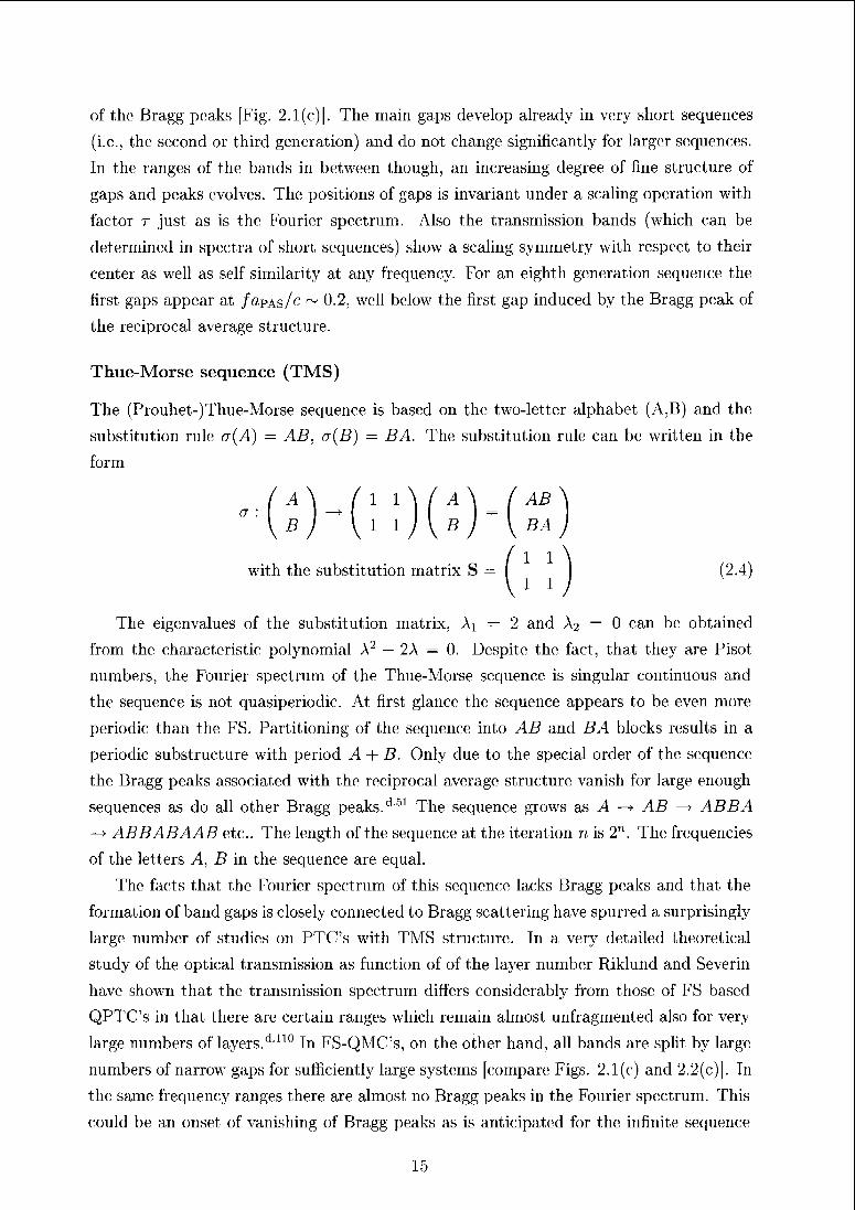
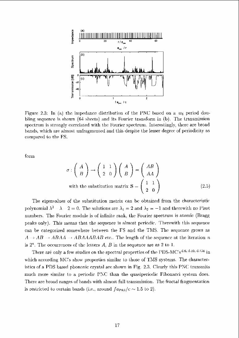
Figure 2.3: In (a) the impedance distribution of the PNC based on a Wq period dou¬
bling sequence is shown (64 sheets) and its Fourier transform in (b). The transmission
spectrum is strongly correlated with the Fourier spectrum. Interestingly, thcie are broad
bands, which are almost unfragmented and this despite the lesser degree of periodicity as
compared to the FS.
form
a
with the substitution matrix S (2.5)
The eigenvalues of the substitution matrix can be obtained from the characteristic
polynomial A2 — A — 2 = 0. The solutions aie Ai — 2 and A2 — — 1 and therewith no Pisot
numbers. The Fourier module is of infinite rank, the Fouiier spectrum is atomic (Bragg
peaks only). This means that the sequence is almost periodic. Therewith this sequence
can be categorized somewhere between the FS and the TMS The sequence grows as
A -> AB -> ABAA -> ABAAABAB etc. The length of the sequence at the iteration n
is 2n. The occurrences of the letters A, B in the sequence are as 2 to 1.
There are only a few studies on the spectral properties of the PDS-MC'sd 6'd 10, d 1 ^ in
which according MC's show properties similai to those of TMS systems. The character¬
istics of a PDS based phononic crystal an1 shown in Fig. 2.3. Cleaily this PNC transmits
much more similai to a periodic PNC than the quasiperiodic Fibonacci system does.
There are broad ranges of bands with almost full transmission. The fractal fragmentation
is restricted to certain bands (i.e., around faPAi,/c ~ 1.5 to 2).
17
Other aperiodic sequences of interest
The Rudin-Shapiro sequence bases on a four letter alphabet (A, B, C, D) and the sub¬
stitution rule a(A) = AB, a(B) = AC, a{C) = DB and a{D) = DC Alternatively a
reduced alphabet A, B —> 0 and C, D — 1 can be used. The Fourier spectrum of this
sequence1 is absolute continuous and therefore the sequence was investigated in form of
MC's several times.d 10, d ^ d i55Multilayer structures based on a Cantor set distribution
were investigated by Laviinenko and co-workers.d 7G The self-similarity of the spectral
properties weie demonstrated. In a similar work by Monsoriu et a/.d90 a strong impact
of a PAS was observed.
Modulated structures (MS)
The interesting aspect of modulated structures is that additionally to the fundamental
period, a a second scale is introduced by the period of the modulation, Amod- Modulations
can be introduced either by a periodically varying displacement of scatterers from the
basic structure or by an additional modulation of the materials properties in a MC.
Variation of the two length scales allows to significantly change the properties of a MC.
Also aperiodic sequences can be realized, of course, if the1 ratio of the two periods is
inational [incommensurately modulated structures (IMS)J. While the Fouriei spectrum is
pure point for commensurate modulations (CMS), according to Piange et al.,d lü4 IMS aie
simple prototypes for structures with singular continuous spectra (all depending on a =
^mod/tt)- The Fourier module of a dD modulated structure is of rank (d + m) with m tb°
number of wave vectors needed to describe the modulation. The Fibonacci sequence can
equally well be described as quasiperiodic or as incommensurately modulated structure.
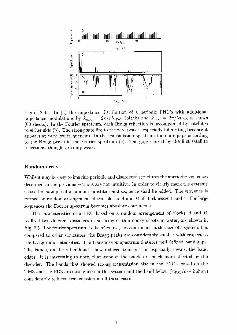
The Fourier spectrum of a periodic MC with a sinusoidally modulated impedance of the
scattering objects [see Fig. 2.4(a)! ('an have just one pair of satellite peaks accompanying
each reflection of the basic structure. There is also such a satellite peak to the reciprocal
origin and this satellite can be very intense.
The transmission spectra foi an IMS and a CMS are compared in Fig. 2.4. The
spectra are very similar at low frequencies. The satellite peaks of each Bragg reflection
introduces satellite bands to either side of the main gaps for both structures. Towards
higher frequencies moie of the aperiodic nature of the IMS come into play. The higher
bands do not reach full transmission anymore. With regard to applications, the most
interesting question concerns the satellite to the zeio reflection, which is very strong in
the Fourier spectrum. Unfortunately, the resulting attenuation peaks in the transmission
spectrum are only very weak (about 10% for the IMS and 5% for the CMS). The same
also applies to quasiperiodic MC's because also in their Fourier spectra there are Bragg
peaks in close proximity of the origin. Modulated structures are certainly a appropriate
means to study such low frequency dips.
18
(a)
20r/a„
It
wMMT-~-»"Vî
If1kn(c)
1 WJw ,g -40
Figure 2.4: In (a) the impedance distribution of a periodic PNC's with additional
impedance modulations by frmod = 27r/r4apAs (black) and &mod — 27r/5apAs it> shown
(60 sheets). In the Fourier spectrum, each Bragg reflection is accompanied by satellites
to either side (b). The stiong satellite to the zeio peak is especially inteiesting because it
appears at very low frequencies. In the transmission spectrum there aie gaps according
to the Bragg peaks in the Fourier spectrum (c). The gaps caused by the first satellite
reflections, though, are only weak.
Random array-
While it may be easy to imagine periodic and disordered structures the aperiodic sequences
described in the previous sections are not intuitive. In order to clearly mark the extreme
cases the example of a random substitutional sequence shall be added. The sequence is
formed by random arrangement of two blocks A and D of thicknesses 1 and r. For large
sequences the Fourier spectrum becomes absolute continuous.
The characteristics of a PNC based on a random arrangement of blocks A and B,
realized two different distances in an array of thin epoxy sheets in water, are shown in
Fig. 2.5. The fourier spectrum (b) is, of course, not continuous at this size of a system, but
compared to other structures, the Bragg peaks are considerably smaller with respect to
the background intensities. The transmission spectrum features well defined band gaps.
The bands, on the other hand, show reduced transmission especially toward the band
edges. It is interesting to note, that some of the bands are much more affected by the
disorder. The bands that showed strong transmission also in the PNC's based on the
TMS and the PDS are strong also in this system and the band below /apAs/c ~ 2 shows
considerably reduced transmission in all these cases.
19
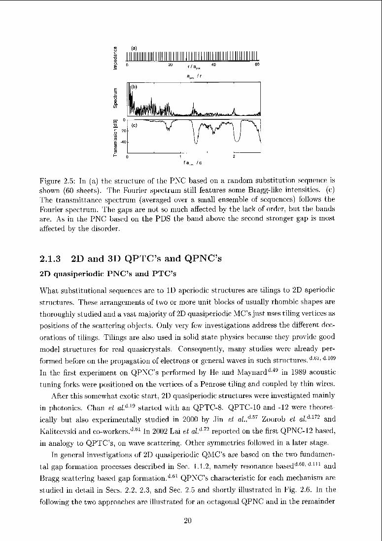
Figure 2.5: In (a) the structure of the PNC based on a random substitution sequence is
shown (60 sheets). The Fourier spectrum still features some Biagg-like intensities, (c)The transmittance spectrum (averaged over a small ensemble of sequences) follows the
Fouiier spectium. The gaps are not so much affected by the lack of order, but the bands
are. As in the PNC based on the PDS the band above the second stronger gap is most
affected by the disorder.
2.1.3 2D and 3D QPTC's and QPNC's
2D quasiperiodic PNC's and PTC's
What substitutional sequences are to ID aperiodic stiuctures are tilings to 2D aperiodic
structures. These arrangements of two or more unit blocks of usually rhombic shapes are
thoroughly studied and a vast majority of 2D quasipeiiodic MC's just uses tiling vertices as
positions of the scattering objects. Only very few investigations address the different dec¬
orations of tilings. Tilings are also used in solid state physics because they provide good
model structures for real quasicrystals. Consequently, many studies were already per¬
formed before on the propagation of electrons or general waves in such structures.d 67> d 109
In the first experiment on QPNC's performed by He and Maynardd 49 in 1989 acoustic-
tuning forks were positioned on the vertices of a Penrose tiling and coupled by thin wire's.
After this somewhat exotic start, 2D quasiperiodic structures were investigated mainly
in photonics. Chan et al.6 19 started with an QPTC-8. QPTC-10 and -12 were theoret¬
ically but also experimentally studied in 2000 by Jin et a/./157 Zoorob et al.d172 and
Kaliteevski and co-workers.d 61 In 2002 Lai et o/.d 72reported on the fiist QPNC-12 based,
in analogy to QPTC's, on wave scattering. Othei symmetries followed in a later stage.
In general investigations of 2D quasiperiodic QMC's are based on the two fundamen¬
tal gap formation processes described in Sec. 1.1.2, namely resonance basedd 60, d in and
Bragg scattering based gap formation.d6t QPNC's characteristic foi each mechanism are
studied in detail in Sees. 2.2, 2.3, and Sec. 2.5 and shortly illustrated in Fig. 2.6. In the
following the two approaches are illustrated for an octagonal QPNC and in the remainder
20
of the section more exotic aperiodic structures are discussed.
Other 2D aperiodic structures
A very simple approach to isotropic band gap materials was suggested by Horiuchi and
co-workers.d-52 They have investigated curve-linear PTC's (CPTC's) which consist of con¬
centric rings of equally spaced cylinders. They can be arbitrarily isotropic and the local
environment surrounding the individual scatterers can be quite simple square or trian¬
gular structures. Nevertheless, such circular structures do no longer have a pure point
Fourier spectrum. But a discrete spectrum is of importance for the existence of Bragg
scattering induced band gaps (see Sees, 1.1.2 and 2.3). Nevertheless, dips in the transmis¬
sion spectrum were observed indicating an omnidirectional band gap (see also Zarbakhsh
et o/.d167).As a veritable alternative to dodecagonal structures David et o/.d'16 have proposed
PTC's based on Archimedean tilings. These structures are related to dodecagonal square
triangle tilings in that they consist of the same building blocks and also have similar local
arrangements in common. As a type1 of approximant, they offer a way to achieve isotropic
band gaps (due to their local 12-fold symmetry) in less complex, periodic structures.
Also in 2D certain fractal structures were investigated by Li and co-workers.<m A
photonic crystal based on a Sirpinski structure was arranged using coaxial cables. Their
findings illustrate how the basic structure is reflected in the transmission spectra and
also how the remaining bands are more and more fragmented with increasing size of the
system. The fabrication of real MC's based on such structures is difficult due to the
very different distances that occur (i.e., these structure do not generally obey the Delone
condition). On the other hand, this is also the main motivation for constructing such
MC's. The different inherent scales can lead do gaps over a broad frequency range. This
was demonstrated also by Sheng and Chan/1125
For all the structures mentioned in this section mainly MC's with resonance-based
gaps are interesting because this mechanism is less demanding for a structure. Thereby
the question about the transmission properties of MC's with random structures naturally
arises. Random structures should, on average, be fully isotropic for infinite systems. In
principle it should be possible to create MC's, which can be described by a tight-binding
Hamiltonian, the transfer integrals of which are very small with respect to its on-site
energies (i.e., very weakly coupled resonances of the single scattering objects). The exact
structure of the system becomes increasingly unimportant the smaller this ratio is. The
factor which is directly related to the coupling strength is the volume fraction of the
scatterers in a MC. For diluted systems the formation of narrow gaps at the resonance
frequencies of the scatterers can be expected. More densely packed systems with smaller
intcr-scatterer distances should stronger respond to the lack of order and localization of
waves can be expected to gradually blurring the clear band structure in a transmission
21
(a) 20
15
10
5
coCO
e_O D
C C
aj g-4-* '-I—'CO ÜO CDCO CO
* * • • • •
t 9—9 * * »
5 10 15 20
r/apas apas ' r
CQ
c
g'cow
"ECOc
cc
0
-20
-40
-600.1
i 1 1
0.2
f r / ccy|
0.3
f apas' c
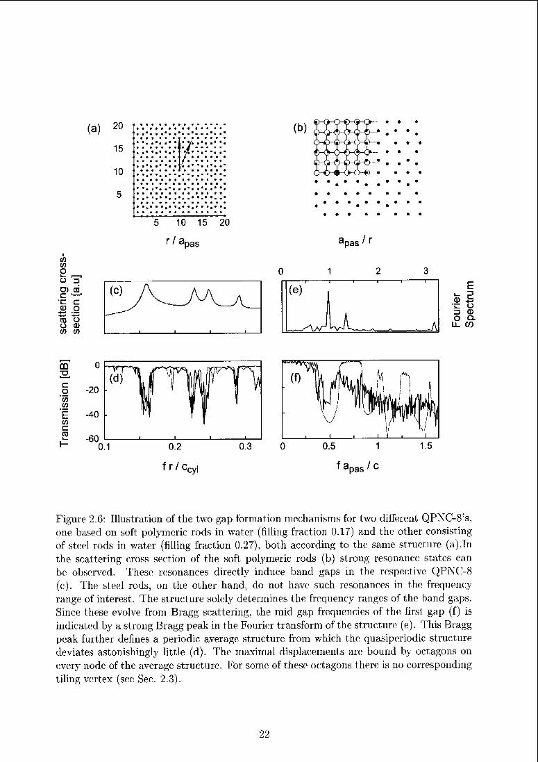
Figure 2.6: Illustration of the two gap formation mechanisms for two different QPNC-8's,
one based on soft polymeric rods in water (filling fraction 0.17) and the other consisting
of steel rods in water (filling fraction 0.27), both according to the same structure (a).Inthe scattering cross section of the soft polymeric rods (b) strong resonance states can
be observed. These resonances directly induce band gaps in the respective QPNC-8
(c). The steel rods, on the other hand, do not have such resonances in the frequency
range of interest. The structure solely determines the frequency ranges of the band gaps.
Since these evolve from Bragg scattering, the mid gap frequencies of the first gap (f) is
indicated by a strong Bragg peak in the Fourier transform of the structure; (e). This Bragg
peak further defines a periodic average structure from which the quasiperiodic structure
deviates astonishingly little (d). The maximal displacements are bound by octagons on
every node of the average structure. For some of these octagons there is no corresponding
tiling vertex (see Sec. 2.3).
22
spectrum (see Rockstuhl et al.dAU and Kaliteevski et al.dAU). In ordered systems, on
the contrary, stronger coupling rather leads to more distrinct band gaps. On the other
hand, if the filling fraction is reduced, the frequency of the first Bragg gap, fBa ~ c/2a0,
decreases too and the structure; becomes more important again due to the; overlap of the
two different scattering regimes. Thus, intermediate filling fractions appear to be most
suitable for random MC's.
3D QPNC's and QPTC's
Studies on MC's with 3D quasiperiodic structures are limited to different realizations of
the icosahedral structure. This structure is discussed in detail in Sec. 2.4.
2.1.4 Applications
While some of the applications based on QMC's can equally be produced from periodic
MC's, there are several aspects inherent to quasiperiodic structures, which make them
especially suitable. Especially the creation of wave guides can profit from the isotropy
and assumed defect insensitivity of QMC's. Waveguiding properties of QPTC-8 were
studied by Cheng and co-workers/120 The influence of the quasiperiodic structure in simple
linear waveguiding systems is difficult to be localized. A higher frequency selectivity was
proposed1' 20 but in general QPTC's mainly provide; omnidirectional band gaps and are
therefore suitable hosts for waveguides with bends/138 Waveguides with up to 180° bends
were shown to be realizable in CPTC's by Zarbakhsh and co-workers.dlf)T A special wave
guide using the coupled resonance states of high symmetry clusters in a QPTC-12 was
presented by Wang and co-workers/1-160 This system, a non-rational approximant of a
QPTC-12, is special in that it does not really contain defects.
More of the quasiperiodic structure can be exploited for the creation of cavities. The
many different vertex coordinations as well as the existence of round cluster motifs, which
can be removed to form resonators, provide a high flexibility for tuning of the frequencies
of corresponding defect modes. d,2° Resonators between adjacent waveguides in QPTC-8
were used to create add/drop filters as was impressively shown by Romero-Vivas and
co-workers.d113
Lasing sytems based on quasiperiodic PTC's wen1 investigated by Notomi et al.d,m
for penrose structure and for dodecagonal QPTC's by Nozaki and co-workers.'1-97 Non¬
linear effects like higher harmonics generation were analyzed for instance in studies by
Zhu et a/.d-m for FS-QPTC by Bratfalean el a/.d15 for penrose structures and for octag¬
onal QPTC's by Ma and co-workers.d-85 An increase in intensity of light extracted from
PTC-based light-emitting diodes was shown to result from changing the PTC structure1
from triangular periodic to dodecagonal quasiperiodic/1169 Superlenses for acoustic waves
exploiting the negative refraction index of QPNC-8, -10, and -12 were analysed by Feng
23
et al.d 35 and by Zhang*
2.1.5 Fabrication of QPTC's and QPNC's
There are many relatively simple methods to create a PNC or a PTC. Arrays of holes can
be mechanically drilled into a flat substrate, surface gratings can be machined or also fibers
or rods can be piled and mechanically connected. The same structuring possibilities are
also provided by etching techniques. These become more and more important the smaller
the constituents of the MC's become, namely in photonics. With these tools almost any
structure can be fabricated in reasonable perfection. However, they appear very inefficient
when thousands of building blocks are required. Techniques which exploit for instance a
naturally occurring ordered system like the inversion of opals or arrangements in colloidal
systems are far more elegant and efficient/1106
However efficient self-assembling routes are they will not likely yield a quasiperiodic
structure. But also other ways of efficient processing have been developed. Optical inter¬
ference lithography (holography) certainly has to be mentioned in this respect. Several
laser beams can be arranged in such a way that their interference pattern is very close
to a quasiperiodic structure.'1'13' *i58 The sets of lines of maximal intensity in such a pat¬
tern form an n-grid. This n-grid is equivalent to rotated periodic average structures of
the quasiperiodic structure, which arc spanned by symmetry equivalent Bragg peaks/1137
The number of laser beams required is equivalent to the order of diffraction symmetry of
the desired structure. Now, the energy accumulated at the maxima of such an interfer¬
ence pattern can be used to process (polymerize) a photo sensitive material. Thereby a
quasiperiodic structure can be obtained in a few seconds time (an overview is given, for
instance, by Escuti and Crawford*33). The quality of the final product can then again
be checked by laser diffraction. Instead of using multiple lasers Yang et al. have sug¬
gested that the interference pattern can also result from diffraction of a single beam on a
mask*148'*105
Interference patterns of multiple lasers can also be used to manipulate diluted col¬
loidal suspensions. Roichman and Gricr*112 have managed to arrange silica spheres on a
quasiperiodic tiling this way. A similarly versatile technique is laser-focused atomic de¬
position (Jurdik et alS1). Atoms, ablated from metallic targets, are guided by standing
waves of multiple laser beams. Thereby, the beam of atoms is focused in the nodes of the
standing waves.
A less elegant but far more flexible way to produce such grids of photoresists is given
by the direct laser writing procedure'1"77 (a collection of articles on this method can be
found in a recent MRS Bulletin*93). In this approach a single low power laser beam is
scanning the whole volume of the sample and by focusing of the beam onto certain spots
the polymerization of the resist is initiated. The resulting grids can be used as templates
for immersion processing (infiltration with a different material and subsequent chemical
24
resolving of the original mask).
Summary
The quite extensive work on quasiperiodic and other aperiodic heterostructures covers a
large variety of different topics. It is fascinating how the mathematics of fractal structures
or the theory of diffraction spectra find their way into the design and practical construction
of an exciting class of materials. The exotic aspect of multifractality can find a direct
implication on the potential of a ID MC (for which transmission and Fourier spectrum
can be very directly correlated) as broad band wave shield with many spectral gaps. The
arbitrarily high rotational symmetry and the still point diffractive spectra of 2D and 3D
quasiperiodic structures can be practically exploited to manufacture isotropic band gap
materials, which are perfectly well suitable to host wave guides or cavities. With the
future capabilities to grow largei and larger sections of QMC's the true nature of their
properties may be even better appreciated. And with the massive promotion they enjoy
currently, the reluctance to use quasiperiodic structures for further technical research on
the host of applications promised could also lessen.
25
2.2 QPNC's and single scatterer resonance states (Ar¬ticle 4)
It has been mentioned before (see Sec. 1.1.2), that strong resonance; states of the single
scattering objects can cause the formation of band gaps in the acoustic dispersion relation
of PNC's. In this article, this is demonstrated for QPNC's. More detailed investigations
of the fields eradiated from rods at resonance frequencies help to understand how this
exactly happens. Thus, the focus is on the properties of the single scattering objects.
D. Sutter and W. Sterner, Phys. Rev. B 75, 134303 (2007).
26
Prediction of band gaps in phononic quasicrystals based on
single-rod resonances
Daniel Sutter-Widmer* and Walter Steurer
Laboratory of Crystallography, Department of Materials,
ETH Zurich, 8093 Zurich, Switzerland
(Dated: March 5, 2007)
Abstract
Band-gap formation in two-dimensional quasipcriodic polymer/water hcterostructures (with 4-
to 14-fold Patterson symmetry in this study) is governed by strong acoustic resonances of the
sound-soft single scatterers. Already with an eightfold-symmetric structure the first band gap is
very isotropic. For isotropy of the higher gaps higher-symmetric structures are required. However,
this can also be achieved by a smart tuning of the properties of the scatterers. Their symmetry
(and therewith the symmetries of the scattered fields) has to better match the symmetry of a given
structure. Polygon- and star-shaped prisms on quasipcriodic structures can yield smoother and
more isotropic gaps in transmission spectra.
PACS numbers: 46.40.Cd, 01.44.Br, 43.35.+d
* Electronic address: [email protected]
27
INTRODUCTION
The study of classical wave propagation in periodic heterostructures, i.e., photonic
(PTC's) and phonemic crystals (PNC's), started almost 20 years ago [1]. Since then, the
promising applications such as optical computers and devices have spurred an almost expo¬
nential growth of the number of publications on PTC's [2] Far less work has been devoted
to PNC's. For these, potential applications are expected in noise control and ultrasonic tech¬
nology, for instance The similarity of PTC's and PNC's allows, to some extent, a knowledge
transfer and increases the impact of discoveries in each field. The fascinating type of com¬
posite materials can be described as one-, two- (2D), oi three-dimensional meta crystals
built of objects which scatter electromagnetic or elastic (acoustic) waves if the wavelength
is on the scale of the lattice period (for a comprehensive review, see Ref. 3).
The existence of omnidirectional band gaps, which is important for most applications, is
strongly favored by high symmetries of the heterostructures. The rotational symmetry of
periodic structures is limited to sixfold. For 2D quasiperiodic structures there is no upper
limit and consequently quite a few publications already report the peculiarities of quasiperi¬
odic PTC's (QPTC's) and PNC's (QPNC's) (see Rcfs. 4 8 and references therein). However,
bands and gaps m QPNC's are well defined in particular cases only (l e,in some systems
only pseudogaps were found [9] similar to the electronic pseudogaps of real quasicrystals)
and their formation and structure is not yet thoroughly understood In the following, we
present a study of the scattering properties of single rods and show how this information
supports the understanding of the formation and the optimization of band gaps in QPNC's
The transmission spectra for a square lattice PNC as well as QPNC's with 8-, 10-, 12-, and
14-fold Patterson symmetry (see Fig. 1) were calculated by a finite difference approximation
in the time domain (FDTD) [10]. For the scattering cross-section calculations of cylindri¬
cal rods we have used a multipole-expansion method [11] and for all other rods the FDTD
method.
I. SYSTEMS OF CIRCULAR CYLINDRICAL RODS
The type of scattering in PNC's has been known to be of prime importance ever since the
first PNC's were created. It can be adjusted by the impedance contrast of the constituent
28
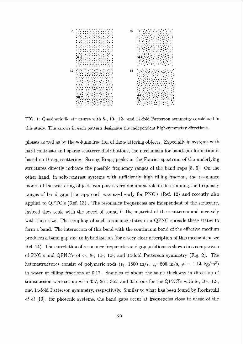
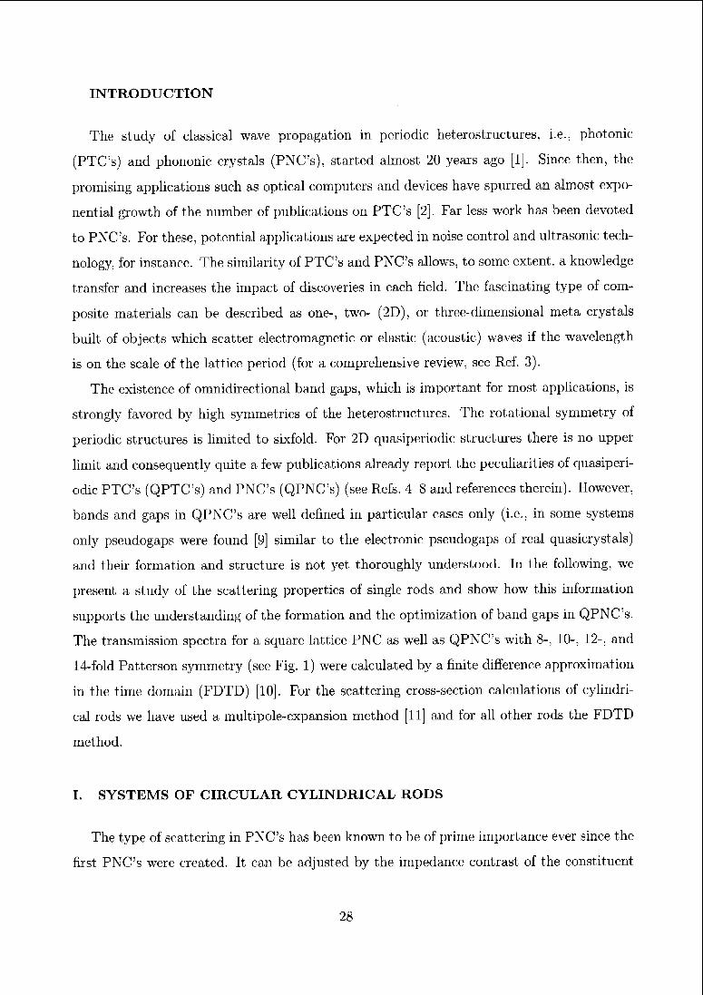
FIG. 1: Quasiperiodic structures with 8-, 10-, 12-, and 14-fold Patterson symmetry considered in
this study. The arrows in each pattern designate the independent high-symmetry directions.
phases as well as by the volume fraction of the scattering objects. Especially in systems with
hard contrasts and sparse scattcrcr distributions, the mechanism for band-gap formation is
based on Bragg scattering. Strong Bragg peaks in the Fourier spectrum of the underlying
structures directly indicate the possible frequency ranges of the band gaps [8, 9]. On the
other hand, in soft-contrast systems with sufficiently high filling fraction, the resonance
modes of the scattering objects can play a very dominant role in determining the frequency
ranges of band gaps [the approach was used early for PNC's (Ref. 12) and recently also
applied to QPTC's (Ref. 13)]. The resonance frequencies are independent of the structure,
instead they scale with the speed of sound in the material of the scatterers and inversely
with their size. The coupling of such resonance states in a QPNC spreads these states to
form a band. The interaction of this band with the continuum band of the effective medium
produces a band gap due to hybridization (for a very clear description of this mechanism see
Ref. 14). The correlation of resonance frequencies and gap positions is shown in a comparison
of PNC's and QPNC's of 4-, 8-, 10-, 12-, and 14-fold Patterson symmetry (Fig. 2). The
heterostructurcs consist of polymeric rods (^=1800 m/s, vs=800 m/s, p = 1.14 kg/m3)
in watei at filling fractions of 0.17. Samples of about the same thickness in direction of
transmission were set up with 357, 361, 365, and 355 rods for the QPNC's with 8-, 10-, 12-,
and 14-fold Patterson symmetry, respectively. Similar to what has been found by Rockstuhl
et al [13]. for photonic systems, the band gaps occur at frequencies close to those of the
29
resonance states in the scattering cross sections of a single rod. Nevertheless, in these
(Q)PNC's the arrangement of the rods does play a crucial role. For the periodic square
lattice PNC the first band gap is shifted by almost as much as its width if the direction of
transmission is changed. A very bad overlap results. This overlap is clearly getting better
with an increasing degree of rotational symmetry of the arrangement of the scatterers. While
for the 8-fold structure mainly the first gap is absolute, for the 12-fold structure all gaps are
perfectly isotropic. The increasing symmetry of the structures also leads to broadened gaps
with less sharp edges (i.e., spikes associated with localized modes appear). This effect can
also be seen as due to more inhomogeneous nearest-neighbor-distance distributions of the
highly symmetric structures. The shorter distances tend to broaden the gap and the wider
spacings to close it. In the square structure all rods have the same coordination and thus the
overlap of their scattered field lobes with those scattered from neighboring rods is equal (i.e.,
equal transfer parameters). Thus, for the formation of isotropic and sharply bound band
gaps a structure with high Patterson symmetry and only few different vertex coordinations
seems most promising (i.e., not a random arrangement). Quasiperiodic structures optimally
combine this.
In order to predict the isotropy of a band gap in (Q)PNC's, the scattered wave field \&s
can be analyzed for the resonance, which induces the gap
Mr, 0) = e1 Y, cm{u)Jm{kr)Cos{m9), (1)
with Jm being Bessel functions of the first kind and cm the coefficients obtained from eval¬
uation of the boundary condition at the cylinder surface [11]. The index m of the strongest
coefficients in the spectrum of the expansion in cylindrical harmonics cm is indicated below
the resonance peaks in Fig. 2. These eigenmodes feature 2777-fold rotational symmetry and in
the case of a single-valued spectrum, the scattered field predominantly adopts the symmetry
of this component.
For transmission in the two high-symmetry directions indicated in Fig. 1, the scattered
waves typically encounter nearest-neighbor rods on vertices of regular ri-sided polygons (with
one vertex in the forward direction) for even and 277-sided polygons for odd n (direction of
dark arrows in Fig. 1) or just between these neighbor vertices (bright arrows). Strong inter¬
action of scattered waves (i.e., a large overlap of the scattered field lobes) occurs most likely
when the field lobes point in the direction of the nearest-neighbor rods. This interaction
30
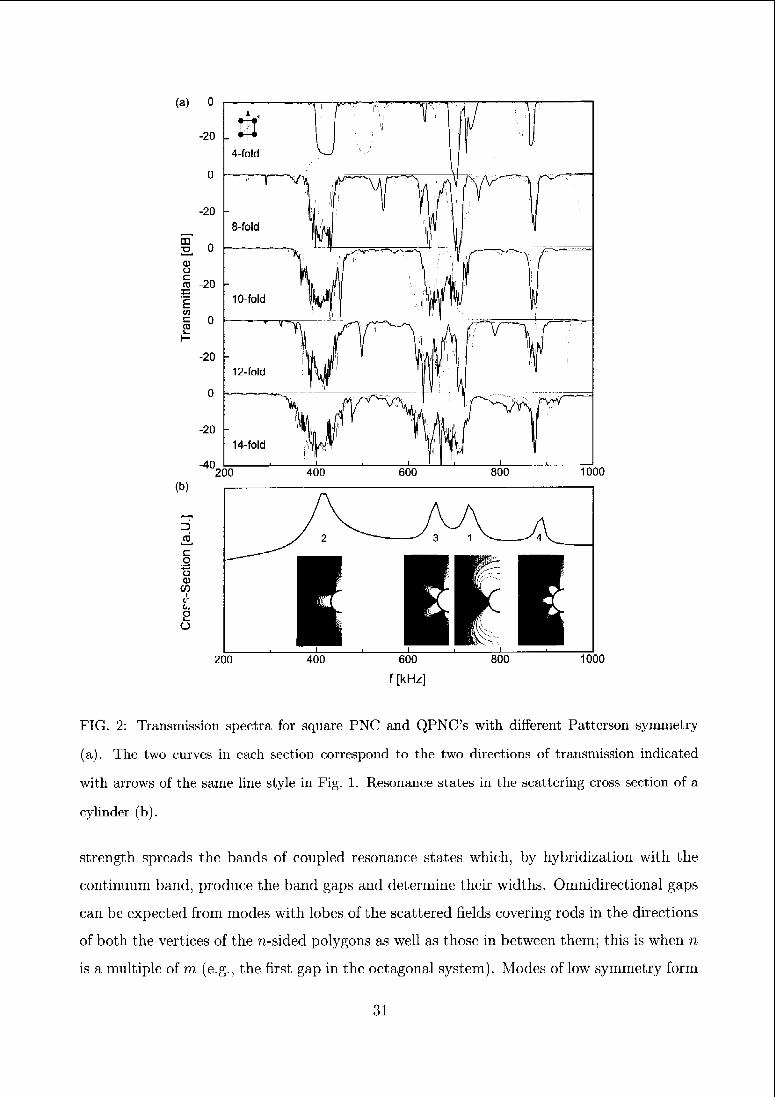
(a)
m
O
i'Ew
c
CD
(b)
ü
COI
</-
t,,
eo
1000
200 400 600
f [kHz]
800 1000
FIG. 2: Transmission spectra for square PNC and QPNC's with different Patterson symmetry
(a). The two curves in each section correspond to the two directions of transmission indicated
with arrows of the same line style in Fig. 1. Resonance states in the scattering cross section of a
cylinder (b).
strength spreads the bands of coupled resonance states which, by hybridization with the
continuum band, produce the band gaps and determine their widths. Omnidirectional gaps
can be expected from modes with lobes of the scattered fields covering rods in the directions
of both the vertices of the n-sided polygons as well as those in between them; this is when n
is a multiple of m (e.g., the first gap in the octagonal system). Modes of low symmetry form
31
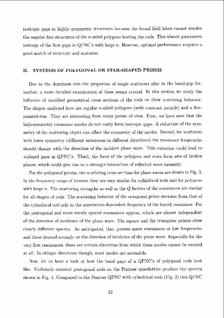
isotropic gaps in highly symmetric structures because the broad field lobes cannot resolve
the angular fine structures of the 7?-sided polygons hosting the rods. This almost guarantees
isotropy of the first gaps in QPNC's with large n. However, optimal performance requires a
good match of structure and scatterer.
II. SYSTEMS OF POLYGONAL OR STAR-SHAPED PRISMS
Due to the dominant role the properties of single scatterers play in the band-gap for¬
mation, a more detailed examination of these seems crucial. In this section we study the
influence of modified geometrical cross sections of the rods on their scattering behavior.
The shapes analyzed here are regular n-sided polygons (with constant incircle) and a five-
pointed-star. They are interesting from many points of view. First, we have seen that the
high-symmetry resonance modes do not easily form isotropic gaps. A reduction of the sym¬
metry of the scattering object can affect the symmetry of the modes. Second, for scatterers
with lower symmetry (diffeient extensions in different directions) the resonance frequencies
should change with the direction of the incident plane wave. This variation could lead to
widened gaps in QPNC's. Third, the faces of the polygons and stars form sets of broken
planes, which could give rise to a stronger interaction of reflected wave intensity.
For the polygonal prisms, the scattering cross sections for plane waves are shown in Fig. 3.
In the frequency range of interest they are very similar for cylindrical rods and for polygons
with large n. The scattering strengths as well as the Q factors of the resonances are similar
for all shapes of rods. The scattering behavior of the octagonal prism deviates from that of
the cylindrical rod only in the orientation-dependent frequency of the fourth resonance. For
the pentagonal rod more evenly spaced resonances appear, which are almost independent
of the direction of incidence of the plane wave. The square and the triangular prisms show
clearly different spectra. As anticipated, they possess more resonances at low frequencies
and these depend strongly on the direction of incidence of the plane wave. Especially for the
very first resonances, there are certain directions from which these modes cannot be excited
at all. In oblique directions though, most modes are accessible.
Now, let us have a look at how the band gaps of a QPNC's of polygonal rods look
like. Uniformly oriented pentagonal rods on the Penrose quasilattice produce the spectra
shown in Fig. 4. Compared to the Penrose QPNC with cylindrical rods (Fig. 2) this QPNC
32
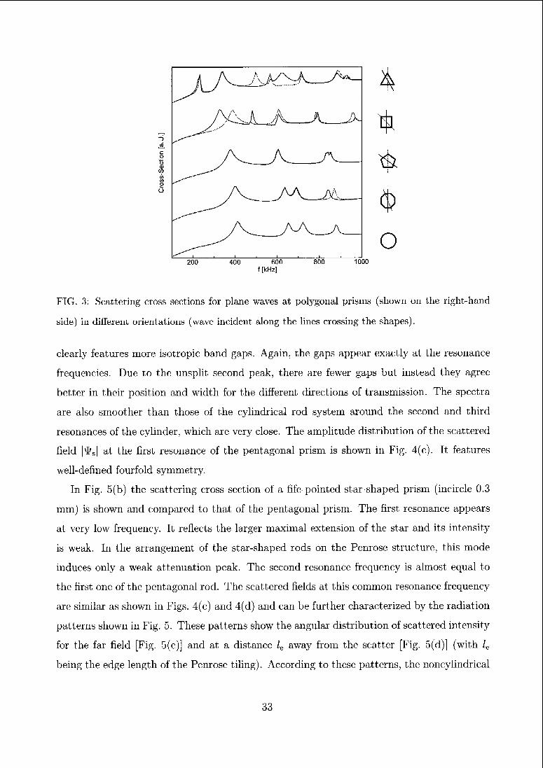
o200 400 600 800 1000
f [kHz]
FIG. 3: Scattering cross sections for plane waves at polygonal prisms (shown on the right-hand
side) in different orientations (wave incident along the lines crossing the shapes).
clearly features more isotropic band gaps. Again, the gaps appear exactly at the resonance
frequencies. Due to the unsplit second peak, there are fewer gaps but instead they agree
better in their position and width for the different directions of transmission. The spectra
are also smoother than those of the cylindrical rod system around the second and third
resonances of the cylinder, which arc very close. The amplitude distribution of the scattered
field |^s| at the first resonance of the pentagonal prism is shown in Fig. 4(c). It features
well-defined fourfold symmetry.
In Fig. 5(b) the scattering cross section of a fife-pointed-star-shaped prism (incirclc 0.3
mm) is shown and compared to that of the pentagonal prism. The first resonance appears
at very low frequency. It reflects the larger maximal extension of the star and its intensity
is weak. In the arrangement of the star-shaped rods on the Penrose structure, this mode
induces only a weak attenuation peak. The second resonance frequency is almost equal to
the first one of the pentagonal rod. The scattered fields at this common resonance frequency
are similar as shown in Figs. 4(c) and 4(d) and can be further characterized by the radiation
patterns shown in Fig. 5. These patterns show the angular distribution of scattered intensity
for the far field [Fig. 5(c)] and at a distance le away from the scatter [Fig. 5(d)] (with le
being the edge length of the Penrose tiling). According to these patterns, the noncylindrical
33
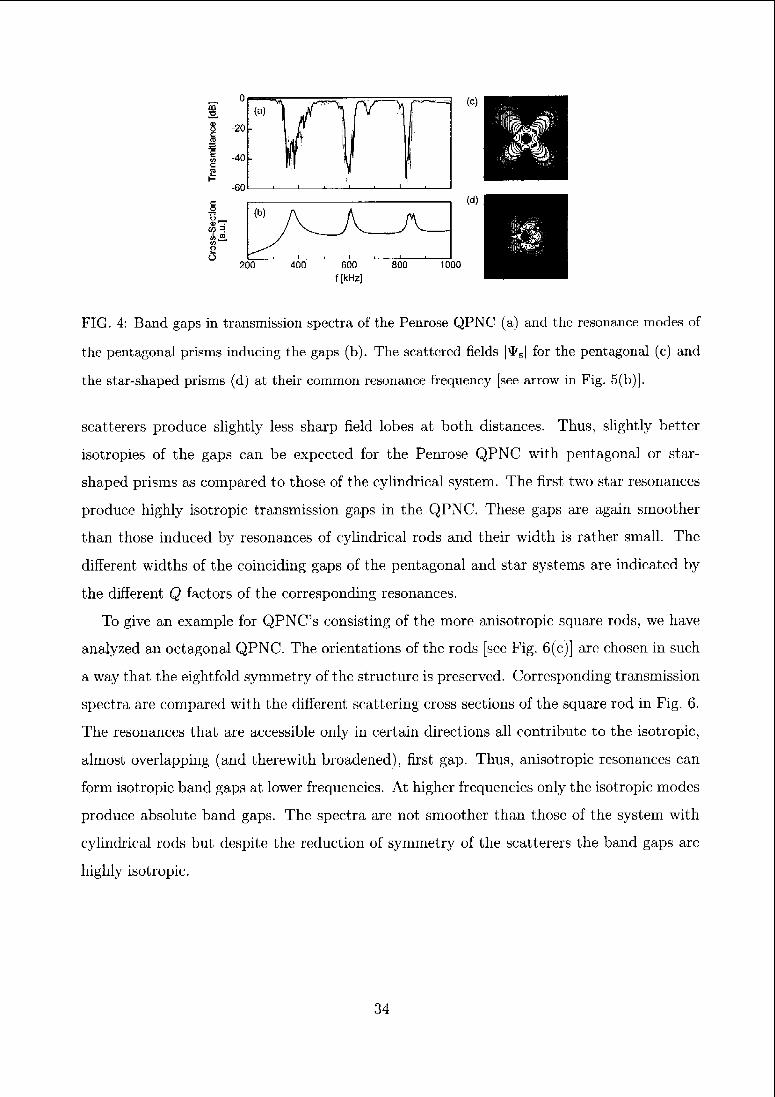
FIG. 4: Band gaps in transmission spectra of the Penrose QPNC (a) and the resonance modes of
the pentagonal prisms inducing the gaps (b). The scattered fields |\I/S| for the pentagonal (c) and
the star-shaped prisms (d) at their common resonance frequency [see arrow in Fig. 5(b)].
scatterers produce slightly less sharp field lobes at both distances. Thus, slightly better
isotropies of the gaps can be expected for the Penrose QPNC with pentagonal or star-
shaped prisms as compared to those of the cylindrical system. The first two star resonances
produce highly isotropic transmission gaps in the QPNC. These gaps are again smoother
than those induced by resonances of cylindrical rods and their width is rather small. The
different widths of the coinciding gaps of the pentagonal and star systems are indicated by
the different Q factors of the corresponding resonances.
To give an example for QPNC's consisting of the more anisotropic square rods, we have
analyzed an octagonal QPNC. The orientations of the rods [see Fig. 6(c)] are chosen in such
a way that the eightfold symmetry of the structure is preserved. Corresponding transmission
spectra are compared with the different scattering cross sections of the square rod in Fig. 6.
The resonances that are accessible only in certain directions all contribute to the isotropic,
almost overlapping (and therewith broadened), first gap. Thus, anisotropic resonances can
form isotropic band gaps at lower frequencies. At higher frequencies only the isotropic modes
produce absolute band gaps. The spectra are not smoother than those of the system with
cylindrical rods but despite the reduction of symmetry of the scatterers the band gaps arc
highly isotropic.
34
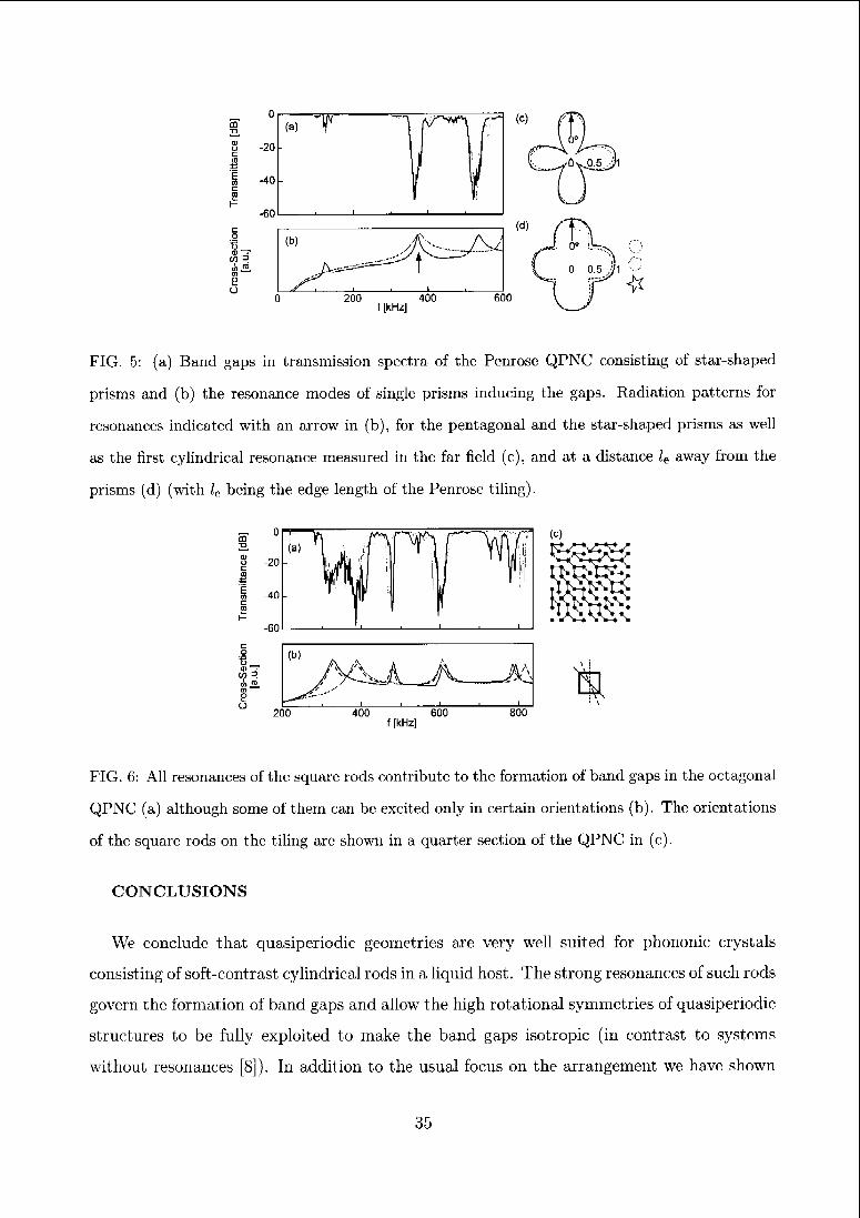
FIG. 5: (a) Band gaps in transmission spectra of the Penrose QPNC consisting of star-shaped
prisms and (b) the resonance modes of single prisms inducing the gaps. Radiation patterns for
resonances indicated with an arrow in (b), for the pentagonal and the star-shaped prisms as well
as the first cylindrical resonance measured in the far field (c), and at a distance le away from the
prisms (d) (with lc being the edge length of the Penrose tiling).
FIG. 6: All resonances of the square rods contribute to the formation of band gaps in the octagonal
QPNC (a) although some of them can be excited only in certain orientations (b). The orientations
of the square rods on the tiling are shown in a quarter section of the QPNC in (c).
CONCLUSIONS
We conclude that quasiperiodic geometries are very well suited for phononic crystals
consisting of soft-contrast cylindrical rods in a liquid host. The strong resonances of such rods
govern the formation of band gaps and allow the high rotational symmetries of quasiperiodic
structures to be fully exploited to make the band gaps isotropic (in contrast to systems
without resonances [8]). In addition to the usual focus on the arrangement we have shown
35
that simpler and more isotropic transmission spectra can be obtained alternatively by using
polygonal or star-shaped rods, the scattered fields of which better match the symmetry of the
structures. The high degree of isotropy seems very promising for all types of applications of
such heterostructures, and may also encourage further analysis of new, interesting building
blocks for phononic as well as photonic crystals other than cylindrical rods.
Acknowledgments
We would like to thank B. Djafari-Rouhani, Y. Pennec, and J. 0. Vasseur for discussions
and for providing the FDTD code we adapted. We also thank Y. Psarobas and R. Sainidou
for discussions.
[1]
[2]
[3:
[4]
[5]
[6
[7]
[8]
[9
[io:
in
[12
[13
[14
E. Yablonovitch, Phys. Rev. Lett. 58, 2059 (1987).
http://ph.ys.lsu.edu/^jdowling/pbgbib.html
M. Sigalas, M. S. Kushwaha, E. N. Economou, M. Kafesaki, I. E. Psarobas, and W. Stcurer,
Z. Kristallogr. 220, 765 (2005).
Y. Lai, Z. Q. Zhang, C. H. Chan, and L. Tsang, Phys. Rev. B 74, 054305 (2006).
Y. Lai, X. Zhang, and Z. Q. Zhang, J. Appl. Phys. 91, 6191 (2002).
M. Hase, H. Miyazaki, M. Egashira, N. Shinya, K. M. Kojima, and S. I. Uchida, Phys. Rev. B
66, 214205 (2002).
D. Sutter and W. Steurer, Phys. Status Solidi C 1, 2716 (2004).
D. Sutter-Widmer, S. Deloudi and W. Steurer, Phys. Rev. B 75, 094304 (2007).
M. A. Kaliteevski, S. Brand, R. A. Abram, T. F. Krauss, R. DeLa Rue, and P. Millar,
Nanotechnology 11, 274 (2000).
B. Djafari-Rouhani, Y. Pennec, and J. 0. Vasseur (private communication).
J. J. Faran, J. Acoust. Soc. Am. 23, 405 (1951).
M. Kafesaki and E. N. Economou, Phys. Rev. B 52, 13317 (1995).
C. Rockstuhl, U. Peschd, and F. Lederer, Opt. Lett. 31, 1741 (2006).
R. Sainidou, N. Stefanou, and A. Modinos, Phys. Rev. B 66, 212301 (2002).
36
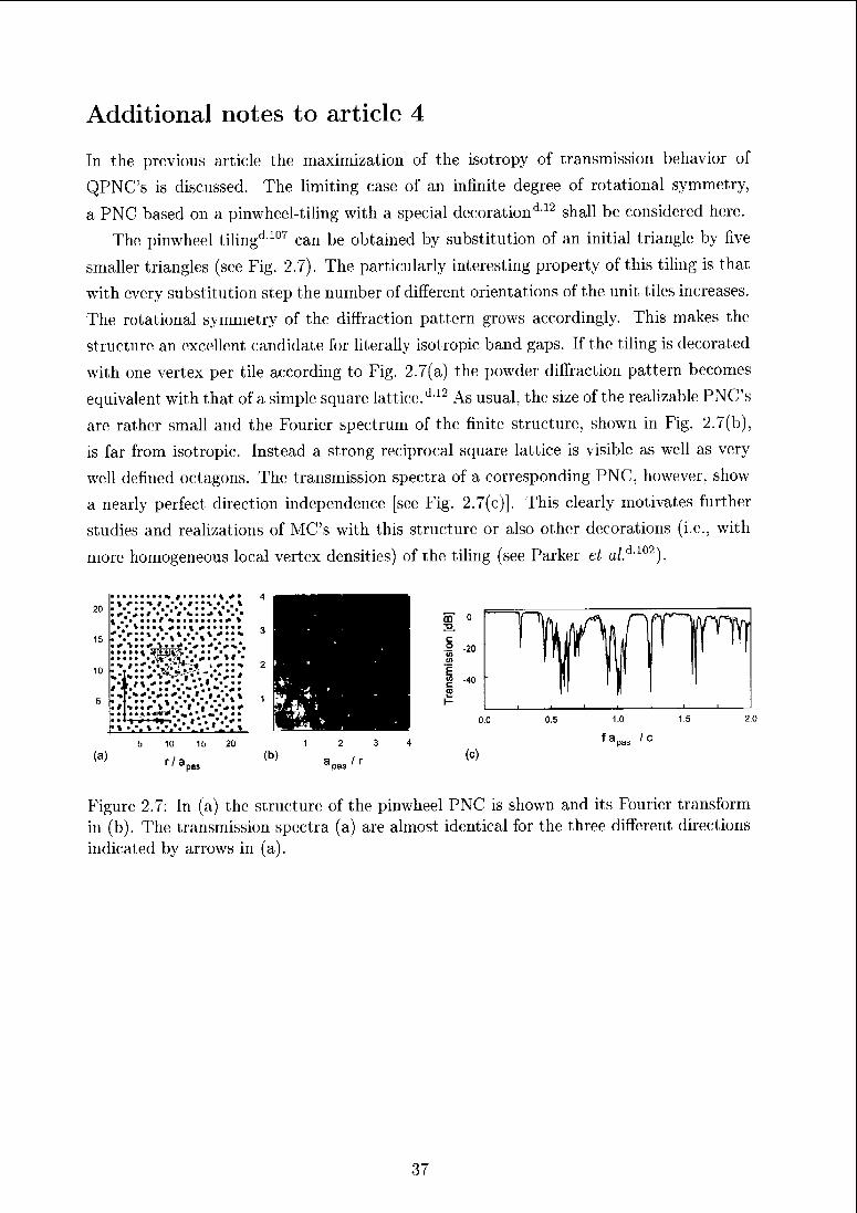
Additional notes to article 4
In the previous article the maximization of the isotropy of transmission behavior of
QPNC's is discussed. The limiting case of an infinite degree of rotational symmetry,
a PNC based on a pinwheel-tiling with a special decoration*1'12 shall be considered here.
The pinwheel tiling'1107 can be obtained by substitution of an initial triangle by five
smaller triangles (see Fig. 2.7). The particularly interesting property of this tiling is that
with every substitution step the number of different orientations of the unit tiles increases.
The rotational symmetry of the diffraction pattern grows accordingly. This makes the
structure an excellent candidate for literally isotropic band gaps. If the tiling is decorated
with one vertex per tile according to Fig. 2.7(a) the powder diffraction pattern becomes
equivalent with that of a simple square lattice.d12 As usual, tin; size of the realizable PNC's
are rather small and the Fourier spectrum of the finite structure, shown in Fig. 2.7(b),
is far from isotropic. Instead a strong reciprocal square lattice is visible as well as very
well defined octagons. The transmission spectra of a corresponding PNC, however, show
a nearly perfect direction independence [see Fig. 2.7(c)]. This clearly motivates further
studies and realizations of MC's with this structure or also other decorations (i.e., with
more homogeneous local vertex densities) of the tiling (see Parker et a/.d102).
* t * <*•
•\ * H t .• • #•! • • *
• #.'*•* •"." t •...+ X '. .
^ B• ••/ ^••••^ \
> * % • • ^ ^ • > ^ • • • • «
*,**•* • .-» •.*.* *••»
Figure 2.7: In (a) the structure of the pinwheel PNC is shown and its Fourier transform
in (b). The transmission spectra (a) are almost identical for the three different directions
indicated by arrows in (a).
37
2.3 QPNC's and Bragg scattering (Article 5)
In the overview of ID QPNC's (Sec. 2.1.2) the direct connection of the Fourier spectrum
and the transmission spectrum is demonstrated. If there aie no single rod resonances (as
discussed in the previous section) in the frequency range of interest then this connection
is valid also for 2D QPNC's. Beyond the positions of the band gaps the Fourier spectrum
provides information about the periodic average structures of a quasiperiodic pattern. In
this article periodic average structures are used to interpret the transmission spectra and
explain the occurrence 01 absence of clear band gaps.'1143
D. Sutter, S. Deloudi and W. Steuier, Phys Rev. B 75, 094304 (2007).
38
Prediction of Bragg-scattering-induced band gaps in phononic
quasicrystals
Daniel Sutter-Widmer,* Sofia Dcloudi, and Walter Steurer
Laboratory of Crystallography, Department of Materials,
ETE Zurich, 8093 Zurich, Switzerland
(Dated: January 16, 2007)
Abstract
We have studied ultrasonic wave propagation in two-dimensional quasiperiodic steel/water het-
erostructures with 8-, 10-, 12-, and 14-fold Patterson symmetry. The formation of band gaps in this
kind of quasiperiodic phononic crystal (QPNC) is mainly governed by multiple Bragg scattering.
The particular role of the periodic average structure of the QPNC in prediction and understanding
of their transmission spectra is shown. The smaller the deviations from average periodicity, the
greater is the similarity of transmission spectra of the quasiperiodic and periodic heterostructures.
Consequently, QPNC's with eightfold symmetry (QPNC-8's) show much better defined transmit-
tance bands and gaps than QPNC-10's and QPNC-14's, whose spectra resemble more those of
disordered periodic systems. Smoother transmission spectra with clear gaps can be obtained by
replacement of the cylinders of QPNC-10's by star-shaped prisms.
PACS numbers: 61.44.Br, 46.40.Cd, 43.35.+d
"Electronic address: daniel.sutterOmat .ethz.ch
39
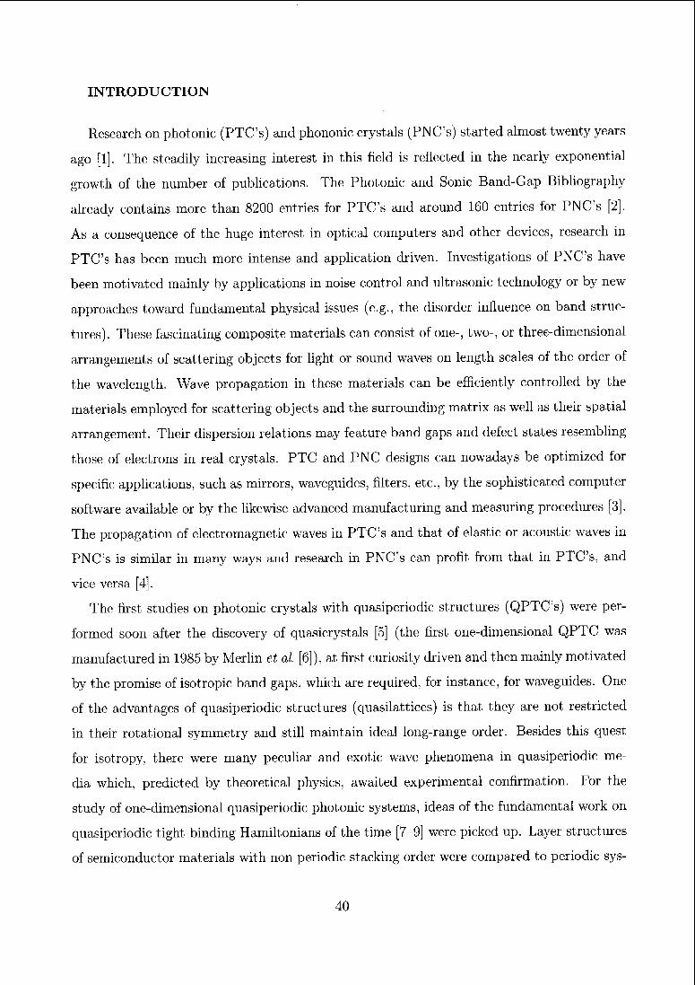
INTRODUCTION
Research on photonic (PTC's) and phononic crystals (PNC's) started almost twenty years
ago [1]. The steadily increasing interest in this field is reflected in the nearly exponential
growth of the number of publications. The Photonic and Sonic Band-Gap Bibliography
already contains more than 8200 entries for PTC's and around 160 entries for PNC's [2].
As a consequence of the huge interest in optical computers and other devices, research in
PTC's has been much more intense and application driven. Investigations of PNC's have
been motivated mainly by applications in noise control and ultrasonic technology or by new
approaches toward fundamental physical issues (e.g., the disorder influence on band struc¬
tures). These fascinating composite materials can consist of one-, two-, or three-dimensional
arrangements of scattering objects for light or sound waves on length scales of the order of
the wavelength. Wave propagation in these materials can be efficiently controlled by the
materials employed for scattering objects and the surrounding matrix as well as their spatial
arrangement. Their dispersion relations may feature band gaps and defect states resembling
those of electrons in real crystals. PTC and PNC designs can nowadays be optimized for
specific applications, such as mirrors, waveguides, filters, etc., by the sophisticated computer
software available or by the likewise advanced manufacturing and measuring procedures [3].
The propagation of electromagnetic waves in PTC's and that of elastic or acoustic waves in
PNC's is similar in many ways and research in PNC's can profit from that in PTC's, and
vice versa [4].
The first studies on photonic crystals with quasiperiodic structures (QPTC's) were per¬
formed soon after the discovery of quasierystals [5] (the first one-dimensional QPTC was
manufactured in 1985 by Merlin et al. [6]), at first curiosity driven and then mainly motivated
by the promise of isotropic band gaps, which are required, for instance, for waveguides. One
of the advantages of quasiperiodic structures (quasilattices) is that they are not restricted
in their rotational symmetry and still maintain ideal long-range order. Besides this quest
for isotropy, there were many peculiar and exotic wave phenomena in quasiperiodic me¬
dia which, predicted by theoretical physics, awaited experimental confirmation. For the
study of one-dimensional quasiperiodic photonic systems, ideas of the fundamental work on
quasiperiodic tight-binding Hamiltonians of the time [7-9] were picked up. Layer structures
of semiconductor materials with non periodic stacking order were compared to periodic sys-
40
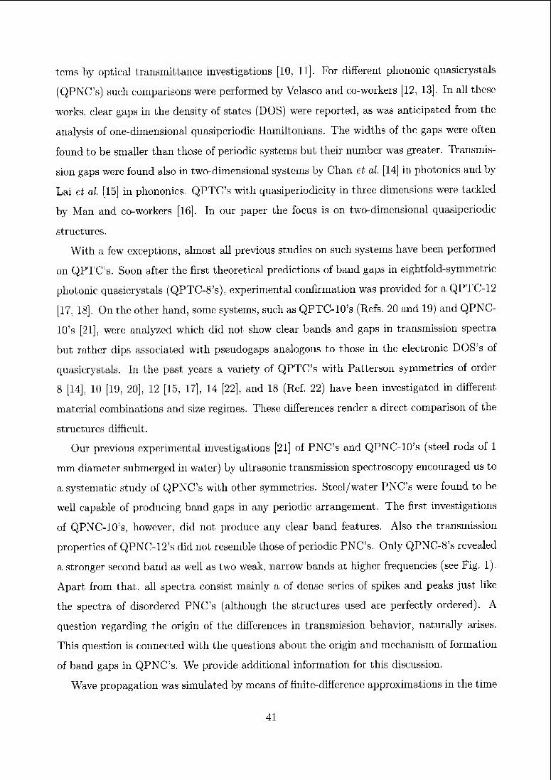
terns by optical transmittance investigations [10, 11]. For different phononic quasicrystals
(QPNC's) such comparisons were performed by Velasco and co-workers [12, 13]. In all these
works, clear gaps in the density of states (DOS) were reported, as was anticipated from the
analysis of one-dimensional quasiperiodic Hamiltonians. The widths of the gaps were often
found to be smaller than those of periodic systems but their number was greater. Transmis¬
sion gaps were found also in two-dimensional systems by Chan et al. [14] in photonics and by
Lai et al. [15] in phononics. QPTC's with quasiperiodicity in three dimensions were tackled
by Man and co-workers [16]. In our paper the focus is on two-dimensional quasiperiodic
structures.
With a few exceptions, almost all previous studies on such systems have been performed
on QPTC's. Soon after the first theoretical predictions of band gaps in eightfold-symmetric
photonic quasicrystals (QPTC-8's), experimental confirmation was provided for a QPTC-12
[17, 18]. On the other hand, some systems, such as QPTC-10's (Refs. 20 and 19) and QPNC-
10's [21], were analyzed which did not show clear bands and gaps in transmission spectra
but rather dips associated with pseudogaps analogous to those in the electronic DOS's of
quasicrystals. In the past years a variety of QPTC's with Patterson symmetries of order
8 [14], 10 [19, 20], 12 [15, 17], 14 [22], and 18 (Rcf. 22) have been investigated in different
material combinations and size regimes. These differences render a direct comparison of the
structures difficult.
Our previous experimental investigations [21] of PNC's and QPNC-10's (steel rods of 1
mm diameter submerged in water) by ultrasonic transmission spectroscopy encouraged us to
a systematic study of QPNC's with other symmetries. Steel/water PNC's were found to be
well capable of producing band gaps in any periodic arrangement. The first investigations
of QPNC-10's, however, did not produce any clear band features. Also the transmission
properties of QPNC-12's did not resemble those of periodic PNC's. Only QPNC-8's revealed
a stronger second band as well as two weak, narrow bands at higher frequencies (see Fig. 1).
Apart from that, all spectra consist mainly a of dense series of spikes and peaks just like
the spectra of disordered PNC's (although the structures used are perfectly ordered). A
question regarding the origin of the differences in transmission behavior, naturally arises.
This question is connected with the questions about the origin and mechanism of formation
of band gaps in QPNC's. We provide additional information for this discussion.
Wave propagation was simulated by means of finite-difference approximations in the time
41
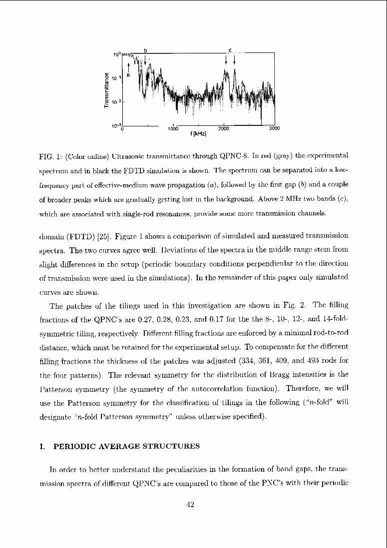
10°
g io-1
"E
I io-2
100 1000 2000 3000
f [kHz]
FIG. 1: (Color online) Ultrasonic transmittance through QPNC-8. In red (gray) the experimental
spectrum and in black the FDTD simulation is shown. The spectrum can be separated into a low-
frequency part of effective-medium wave propagation (a), followed by the first gap (b) and a couple
of broader peaks which are gradually getting lost in the background. Above 2 MHz two bands (c),
which are associated with single-rod resonances, provide some more transmission channels.
domain (FDTD) [25], Figure 1 shows a comparison of simulated and measured transmission
spectra. The two curves agree well. Deviations of the spectra in the middle range stem from
slight differences in the setup (periodic boundary conditions perpendicular to the direction
of transmission were used in the simulations). In the remainder of this paper only simulated
curves are shown.
The patches of the tilings used in this investigation are shown in Fig. 2. The filling
fractions of the QPNC's are 0.27, 0.28, 0.23, and 0.17 for the the 8-, 10-, 12-, and 14-fold-
symmetric tiling, respectively. Different filling fractions arc enforced by a minimal rod-to-rod
distance, which must be retained for the experimental setup. To compensate for the different
filling fractions the thickness of the patches was adjusted (334, 361, 409, and 493 rods for
the four patterns). The relevant symmetry for the distribution of Bragg intensities is the
Patterson symmetry (the symmetry of the autocorrelation function). Therefore, we will
use the Patterson symmetry for the classification of tilings in the following ("n-fold" will
designate "n-fold Patterson symmetry" unless otherwise specified).
I. PERIODIC AVERAGE STRUCTURES
In order to better understand the peculiarities in the formation of band gaps, the trans¬
mission spectra of different QPNC's are compared to those of the PNCs with their periodic
42
J I I L.
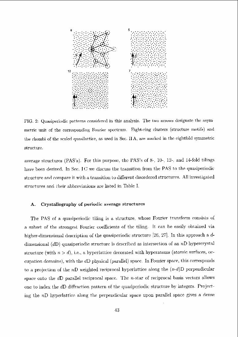
FIG. 2: Quasiperiodic patterns considered in this analysis. The two arrows designate the asym¬
metric unit of the corresponding Fourier spectrum. Eight-ring clusters (structure motifs) and
the rhomtai of the scaled quasilattice, as used in Sec. IIA, are marked in the eightfold-symmetric
structure.
average structures (PAS's). For this purpose, the PAS's of 8-, 10-, 12-, and 14-fold tilings
have been derived. In Sec. IC we discuss the transition from the PAS to the quasiperiodic
structure and compare it with a transition to different disordered structures. All investigated
structures and their abbreviations are listed in Table I.
A. Crystallography of periodic average structures
The PAS of a quasiperiodic tiling is a structure, whose Fourier transform consists of
a subset of the strongest Fourier coefficients of the tiling. It can be easily obtained via
higher-dimensional description of the quasiperiodic structure [26, 27]. In this approach a d-
dimensional (dD) quasiperiodic structure is described as intersection of an nD hypercrystal
structure (with n > d), i.e., a hyperlattice decorated with hypcratoms (atomic surfaces, oc¬
cupation domains), with the dD physical (parallel) space. In Fourier space, this corresponds
to a projection of the nD weighted reciprocal hyperlattice along the (n-d)D perpendicular
space onto the dD parallel reciprocal space. The n-star of reciprocal basis vectors allows
one to index the dD diffraction pattern of the quasiperiodic structure by integers. Project¬
ing the nD hyperlattice along the perpendicular space upon parallel space gives a dense
43
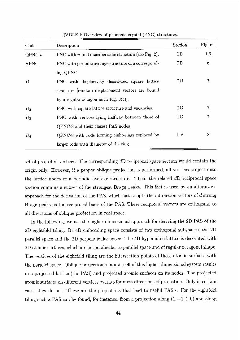
TABLE I: Overview of phononic crystal (PNC) structures.
Code Description Section Figures
QPNC-n PNC with n-fold quasiperiodic structure (see Fig. 2). IB 1,6
APNC PNC with periodic average structure of a correspond- IB 6
ing QPNC.
Di PNC with displacively disordered square lattice IC 7
structure [random displacement vectors are bound
by a regular octagon as in Fig. 3(c)].
Di PNC with square lattice structure and vacancies. IC 7
Di PNC with vertices lying halfway between those of IC 7
QPNC-8 and their closest PAS nodes
D\ QPNC-8 with rods forming eight-rings replaced by IIA 8
larger rods with diameter of the ring.
set of projected vertices. The corresponding dD reciprocal space section would contain the
origin only. However, if a proper oblique projection is performed, all vertices project onto
the lattice nodes of a periodic average structure. Then, the related f/D reciprocal space
section contains a subset of the strongest Bragg Peaks. This fact is used by an alternative
approach for the derivation of the PAS, which just adopts the diffraction vectors of d strong
Bragg peaks as the reciprocal basis of the PAS. These reciprocal vectors are orthogonal to
all directions of oblique projection in real space.
In the following, we use the higher-dimensional approach for deriving the 2D PAS of the
2D eightfold tiling. Its 4D embedding space consists of two orthogonal subspaces, the 2D
parallel space and the 2D perpendicular space. The 4D hypercubic lattice is decorated with
2D atomic surfaces, which are perpendicular to parallel space and of regular octagonal shape.
The vertices of the eightfold tiling are the intersection points of these atomic surfaces with
the parallel space. Oblique projection of a unit cell of this higher-dimensional system results
in a projected lattice (the PAS) and projected atomic surfaces on its nodes. The projected
atomic surfaces on different vertices overlap for most directions of projection. Only in certain
cases they do not. These are the projections that lead to useful PAS's. For the eightfold
tiling such a PAS can be found, for instance, from a projection along (1, —1,1,0) and along
44
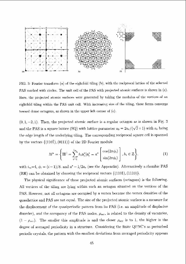
(a)
i
#. •. _ _ . »
i
.- .
I
'"! '
i •
• # -. i;:...
#ii
•
*
%
"
*
ti —....,,,. . .. —:
I.'J.VIAri.*.;..!
(c)
il&, >::oxo::::&:
FIG. 3: Fourier transform (a) of the eightfold tiling (b), with the reciprocal lattice of the selected
PAS marked with circles. The unit cell of the PAS with projected atomic surfaces is shown in (c).
Here, the projected atomic surfaces were generated by taking the modulus of the vertices of an
eightfold tiling within the PAS unit cell. With increasing size of the tiling, these forms converge
toward dense octagons, as shown in the upper left corner of (c).
(0,1, -2,1). Then, the projected atomic surface is a regular octagon as is shown in Fig. 3
and the PAS is a square lattice (SQ) with lattice parameter a0 — 2ar/(v/2 +1) with aT being
the edge length of the underlying tiling. The corresponding reciprocal square cell is spanned
by the vectors {(110Ï), (Olli)} of the 2D Fourier module
M* Hll = 5>a*|a* = a*
i=i
,hi e TL 1)
COs(27T0j)
sin(27T0j)
with z„,=4, 0i — (z — l)/8, and a* - l/2or (see the Appendix). Alternatively a rhombic PAS
(RH) can be obtained by choosing the reciprocal vectors {(110Ï), (1110)}.
The physical significance of these projected atomic surfaces (octagons) is the following.
All vertices of the tiling are lying within such an octagon situated on the vertices of the
PAS. However, not all octagons are occupied by a vertex because the vertex densities of the
quasilattice and PAS are not equal. The size of the projected atomic surface is a measure for
the displacement of the quasiperiodic pattern from its PAS (i.e. an amplitude of displacive
disorder), and the occupancy of the PAS nodes, pocc, is related to the density of vacancies,
(1 — pocc)- The smaller this amplitude is and the closer pocc is to 1, the higher is the
degree of averaged periodicity in a structure. Considering the finite QPNC's as perturbed
periodic crystals, the pattern with the smallest deviations from averaged periodicity appears
45
to be most likely the one with deep and wide gaps in the DOS, comparable to those in
PNC's. Therefore a classification of tilings according to the ratio aa of the area covered
by the projected atomic surface to the size of the PAS unit cell and also pucc is given here.
In general, a quasiperiodic tiling has infinitely many possible PAS's [27], as for instance
a*1 = a1/(y/2 + l)n, reflecting the scaling symmetry of the Fourier transform of the tiling.
The most relevant and interesting PAS's arc those with the smallest aa, with cell sizes
comparable to the tiling edge lengths (i.e., occupancy factors close to 1, because aa —» 0 for
large n), and with strong Bragg peaks. Values for aa as well as amax, the maximal, and ä,
the average, displacement of tiling vertices from the average structure are given in Tab. II
and occupancy factors can be found in Table III.
For the eightfold tiling, there is only one single atomic surface. The 10-, 12-, and 14-
fold tilings arc all generated by atomic surfaces consisting of several disconnected parts.
To illustrate the displacements of the tilings from their PAS's the modulus of all vertex
coordinates within the PAS unit cell can be calculated. For large tilings this draws nicely
the contours of the projected atomic surfaces [see Figs. 3(c), 4, and 5], The comparison
clearly reveals a homogeneous distribution of vertices in the octagon and nonhomogeneous
distributions in the projections of the atomic surfaces of the other tilings. Since all sections
of atomic surfaces have constant vertex densities (because they correspond to a projection of
an infinite str^ of the higher-dimensional lattice onto perpendicular space) a vertex density
variation in their projection must be due to overlapping projected parts (except for the 4D
atomic surfaces of the 14-fold tiling).
The tenfold tiling can be generated from a 4D hyperrhombohedral lattice decorated by five
atomic surfaces, i.e., one point at the origin of the 4D unit cell plus four regular pentagons
parallel to the perpendicular space, centered at i/bx (1,1,1,1) for i = 1,..., 4 on the the body
diagonal. It is intuitive to first project along the cell diagonal to ensure overlapping of all
pentagons and then perform a second projection to get the PAS. Choosing (4,1,1,1) as the
latter, a rhombic PAS is obtained which is decorated by the overlapping pentagons [26]. This
PAS corresponds to the vectors {(00Ï1), (01Ï0)} in the reciprocal lattice defined in Eq. (1)
with im — 4, (j)% = i/h, and a* = 2r2/5ar [with the golden ratio r = (%/5 + l)/2 — 1.618].
In the case of the 12-fold tiling, the atomic surfaces in the 6D hypercrystal structure
comprise four triangles and four nonregular hexagons and are parallel to the first perpen¬
dicular subspaee [see {v\,wi} in Eq. (A.3)] and stacked along the diagonal of the unit cell
46
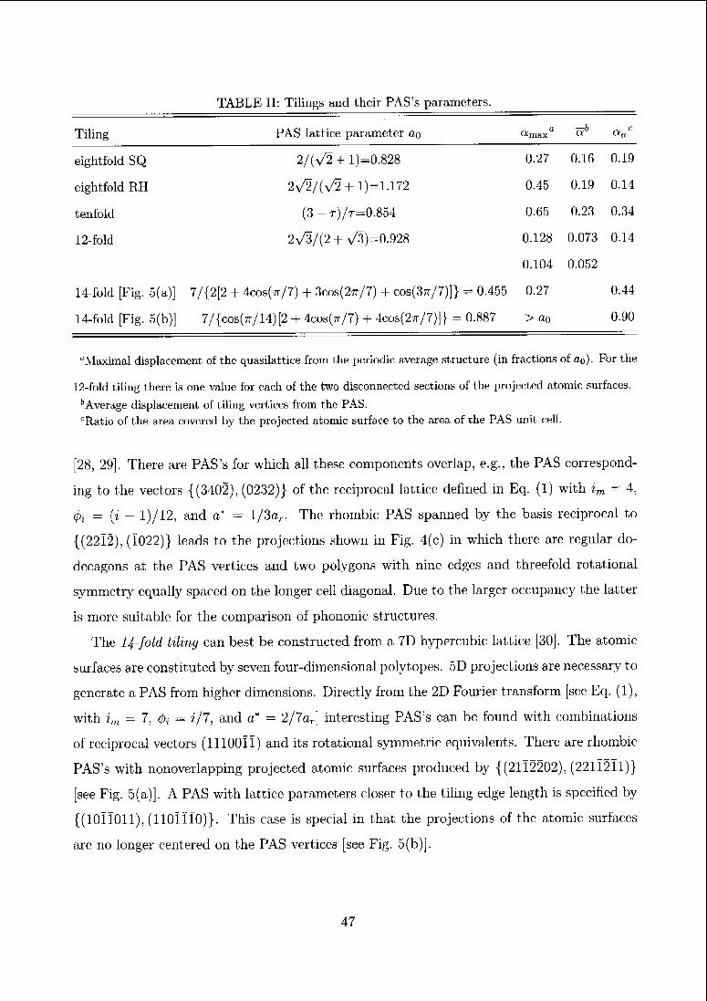
TABLE II: Tilings and their PAS's parameters.
Tiling PAS lattice parameter ciq oiniaxa ah aac
eightfold SQ 2/(v/2 + l)=0.828 0.27 0.16 0.19
eightfold RH 2>/2/(V2 +1)=1.172 0.45 0.19 0.14
tenfold (3-t)/t=0.854 0.65 0.23 0.34
12-fold 2>/3/(2 + a/3)=0.928 0.128 0.073 0.14
0.104 0.052
14-fold [Fig. 5(a)] 7/{2[2 + 4cos(tt/7) + 3cob(2tt/7) + cos(3tt/7)]} = 0.455 0.27 0.44
14-fold [Fig. 5(b)] 7/{cos(tt/14)[2 + 4cos(tt/7) + 4cos(2tt/7)]} = 0.887 > a0 0.90
"Maximal displacement of the quasilattice from the periodic average structure (in fractions of o,q). For the
12-fold tiling there is one value for each of the two disconnected sections of the projected atomic surfaces.
6Average displacement of tiling vertices from the PAS.
rRatio of the area covered by the projected atomic surface to the area of the PAS unit cell.
[28, 29]. There are PAS's for which all these components overlap, e.g., the PAS correspond¬
ing to the vectors {(3402), (0232)} of the reciprocal lattice defined in Eq. (1) with im = 4,
0i — (z — 1)/12, and a* — l/3ar. The rhombic PAS spanned by the basis reciprocal to
{(2212), (Ï022)} leads to the projections shown in Fig. 4(c) in which there are regular do¬
decagons at the PAS vertices and two polygons with nine edges and threefold rotational
symmetry equally spaced on the longer cell diagonal. Due to the larger occupancy the latter
is more suitable for the comparison of phononic structures.
The 14-fold tiling can best be constructed from a 7D hypercubic lattice [30]. The atomic
surfaces are constituted by seven four-dimensional polytopes. 5D projections are necessary to
generate a PAS from higher dimensions. Directly from the 2D Fourier transform [see Eq. (l),
with im — 7, (j), — ?/7, and a* — 2/7o,] interesting PAS's can be found with combinations
of reciprocal vectors (11100ÎÏ) and its rotational symmetric equivalents. There are rhombic
PAS's with nonoverlapping projected atomic surfaces produced by {(2112202), (221Ï2Ï1)}
[see Fig. 5(a)]. A PAS with lattice parameters closer to the tiling edge length is specified by
{(lOÏIOll), (110ÎÏÏ0)}. This case is special in that the projections of the atomic surfaces
arc no longer centered on the PAS vertices [see Fig. 5(b)].
47
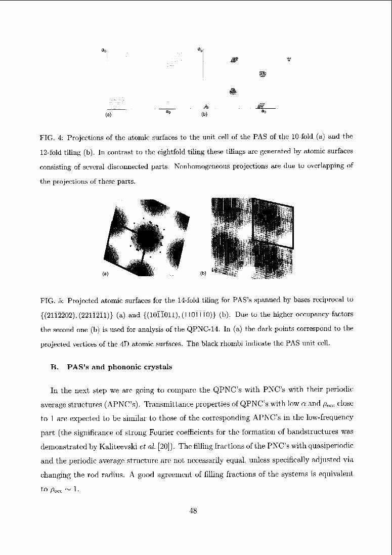
FIG. 4: Projections of the atomic surfaces to the unit cell of the PAS of the 10-fold (a) and the
12-fold tiling (b). In contrast to the eightfold tiling these tilings arc generated by atomic surfaces
consisting of several disconnected parts. Nonhomogcneous projections are due to overlapping of
the projections of these parts.
FIG. 5: Projected atomic surfaces for the 14-fold tiling for PAS's spanned by bases reciprocal to
{(21Ï2202), (221Ï2Ï1)} (a) and {(10ÏÏ011), (110ÏÏÏ0)} (b) Due to the higher occupancy factors
the second one (b) is used for analysis of the QPNC-14. In (a) the dark points correspond to the
projected vertices of the 4D atomic surfaces The black rhombi indicate the PAS unit cell.
B. PAS's and phononic crystals
In the next step we are going to compare the QPNC's with PNC's with their periodic
average structures (APNC's). Transmittance properties of QPNC's with low a and p„(( close
to 1 are expected to be similar to those of the corresponding APNC's in the low-frequency
part (the significance of strong Fourier coefficients for the formation of bandstructures was
demonstrated by Kaliteevski et al. [20]). The filling fractions of the PNC's with quasipenodic
and the periodic average structure are not necessarily equal, unless specifically adjusted via
changing the rod radius. A good agreement of filling fractions of the systems is equivalent
to pocc ~ 1.
(a) (b)
48
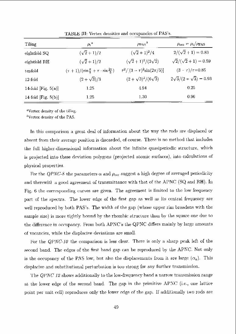
TABLE III: Vertex densities and occupancies of PAS's.
Tiling Pta PPAS1' pocc = Pt/PFAS
eightfold SQ (V2 + l)/2 (V2 + l)2/4 2/(y/2+l) = 0.83
eightfold RH (V2 + l)/2 (^+l)2/(2v^2) v/2/(v/2 + l) = 0.59
tenfold (r + l)/(sinf + r-sinf) r2/[(3 - r)2sin(27r/5)] (3 - r)/r=0.85
12-fold (2 + V3)/3 (2 + v^) 7(6^/3) 2^3/(2+ >/3) -0.93
14-fold [Fig. 5(a)] 1.25 4.94 0.25
14-fold [Fig. 5(b)] 1.25 1.30 0.96
"Vertex density of the tiling.
bVertex density of the PAS.
In this comparison a great deal of information about the way the rods are displaced or
absent from their average position is discarded, of course. There is no method that includes
the full higher-dimensional information about the infinite quasiperiodic structure, which
is projected into these deviation polygons (projected atomic surfaces), into calculations of
physical properties.
For the QPNC-8 the parameters a and pot.c suggest a high degree of averaged periodicity
and therewith a good agreement of transmittance with that of the APNC (SQ and RH). In
Fig. 6 the corresponding curves are given. The agreement is limited to the low-frequency
part of the spectra. The lower edge of the first gap as well as its central frequency are
well reproduced by both PAS's. The width of the gap (whose upper rim broadens with the
sample size) is more tightly bound by the rhombic structure than by the square one due to
the difference in occupancy. From both APNC's the QPNC differs mainly by large amounts
of vacancies, while the displacive deviations are small.
For the QPNC-10 the comparison is less clear. There is only a sharp peak left of the
second band. The edges of the first band gap can be reproduced by the APNC. Not only
is the occupancy of the PAS low, but also the displacements from it are large (aa). This
displacive and substitutional perturbation is too strong for any further transmission.
The QPNC-12 shows additionally to the low-frequency band a narrow transmission range
at the lower edge of the second band. The gap in the primitive APNC (i.e., one lattice
point per unit cell) reproduces only the lower edge of the gap. If additionally two rods are
49
introduced at positions according to the two segments of the projected atomic surface on
the longer diagonal of the PAS unit cell (see Fig. 4), both edges of the gap are reproduced.
Since these segments contribute only about half as many vertices to the tiling as do the
sections on the vertices, the diameter of the added rods was chosen half that of the others.
With these additional vertices, the displacements of the quasilattice from the PAS become
very small and because the period of the system is not changed thereby the occupancy factor
pmi remains close to 1 (however, the occupancy of the additional sites is rather low). The
QPNC-12 can be considered as an APNC with mainly vacancy disordei.
The transmission spectrum for the QPNC-14 shows even fewer cleai features than the
QPNC-10. Only the lower edge of the first gap is reproduced. In contrast to QPNC-8
and -12 this QPNC can be considered as an APNC with almost no vacancies but massive
displacive disorder. In the spectrum, there are no clear features above the first gap.
In summary, a suitable average structure of a QPNC gives information about the first
gap in its transmission spectrum (which is very important foi all applications) as well as
an estimate of transmittance in the second band. Suitable average structures have lattice
constants close to the edge length of the tiles (occupancy factor close to unity) and the
projections of the atomic surfaces are small with respect to the unit cell size. Apart from
providing information about the center and approximate width of the first gap, the average
structures can also be used to estimate its stability in case of deliberately or accidentally
introduced defects. PAS's allow one to comment on the degree of averaged periodicity of the
structure. Periodic structures are, according to Sheng [31], subject to stronger modification
of the band structure under introduction of defects than are strongly disordered structures.
This geometrical characterization of tiling is independent of the current realization of PNC's
as steel rods in water (i.e., physical systems with the structures following an eightfold tiling
are closer to periodicity on average than systems with a 14-fold tiling structure).
C. Transition structures between APNC and QPNC
The following comparison of three types of disordered PAS's of the eightfold tiling is
aimed to show how transmission changes under transition of the PAS to disordered and to
quasiperiodic structures In the first case, a statistically disordered structure {D\), the rods
are displaced from the PAS square lattice by random vectors bound by an octagon (such
50
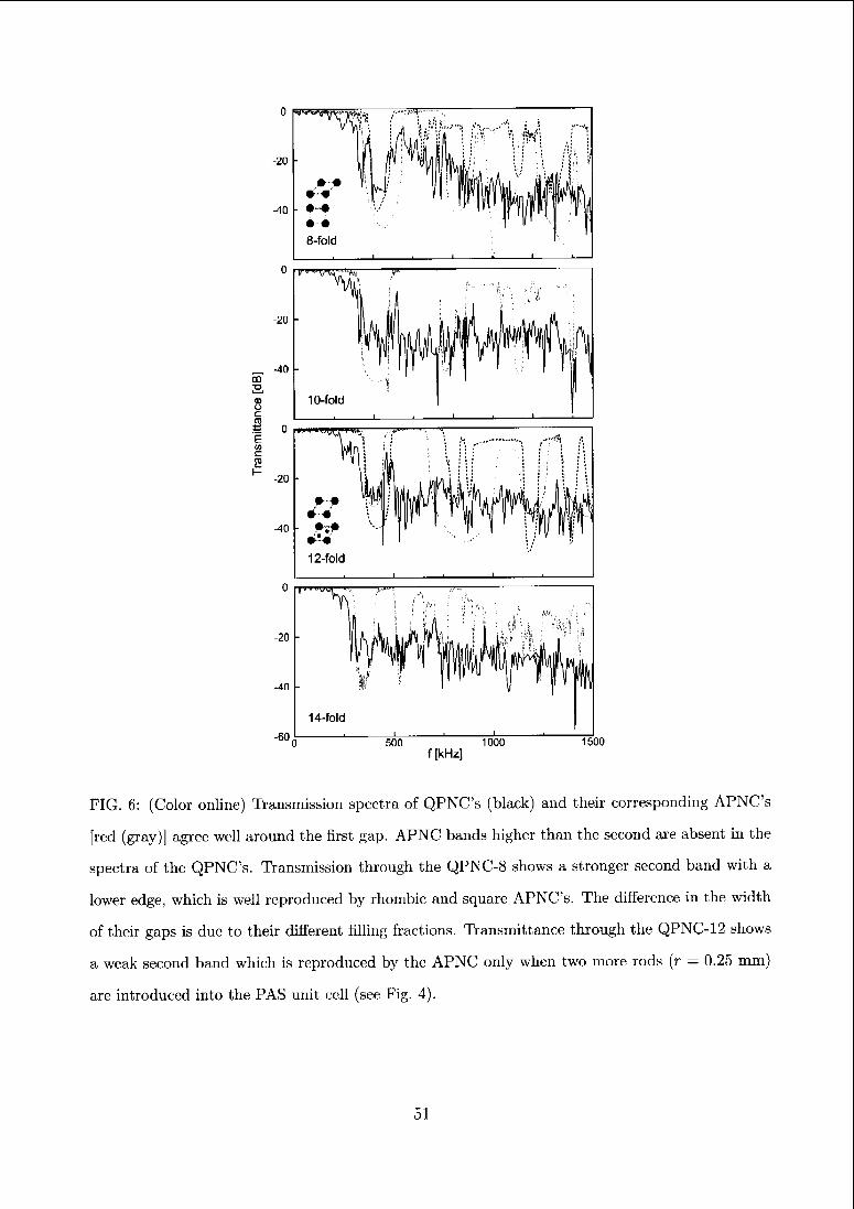
c
Einc
500 1000
f [kHz]1500
FIG. (i: (Color online) Transmission spectra of QPNC's (black) and their corresponding APNC's
[red (gray)] agree well around the first gap. APNC bands higher than the second are absent in the
spectra of the QPNC's. Transmission through the QPNC-8 shows a stronger second band with a
lower edge, which is well reproduced by rhombic and square APNC's. The difference in the width
of their gaps is due to their different filling fractions. Transmittance through the QPNC-12 shows
a weak second band which is reproduced by the APNC only when two more rods (r — 0.25 mm)
are introduced into the PAS unit cell (see Fig. 4).
51
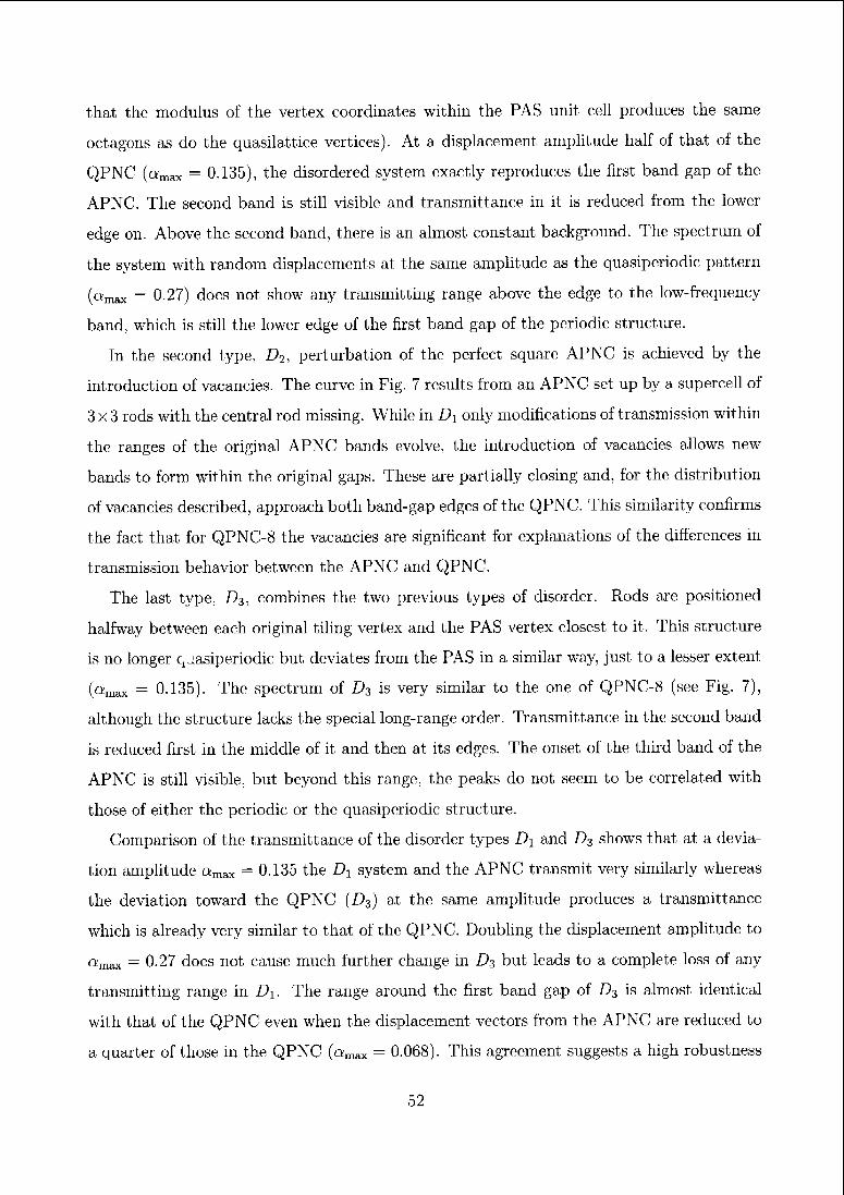
that the modulus of the vertex coordinates within the PAS unit cell produces the same
octagons as do the quasilattice vertices). At a displacement amplitude half of that of the
QPNC (amax = 0.135), the disordered system exactly reproduces the first band gap of the
APNC. The second band is still visible and transmittance in it is reduced from the lower
edge on. Above the second band, there is an almost constant background. The spectrum of
the system with random displacements at the same amplitude as the quasiperiodic pattern
("max — 0.27) does not show any transmitting range above the edge to the low-frequency
band, which is still the lower edge of the first band gap of the periodic structure.
In the second type, D2, perturbation of the perfect square APNC is achieved by the
introduction of vacancies. The curve in Fig. 7 results from an APNC set up by a supercell of
3x3 rods with the central rod missing. While in Dx only modifications of transmission within
the ranges of the original APNC bands evolve, the introduction of vacancies allows new
bands to form within the original gaps. These are partially closing and, for the distribution
of vacancies described, approach both band-gap edges of the QPNC. This similarity confirms
the fact that for QPNC-8 the vacancies are significant for explanations of the differences in
transmission behavior between the APNC and QPNC.
The last type, D3, combines the two previous types of disorder. Rods are positioned
halfway between each original tiling vertex and the PAS vertex closest to it. This structure
is no longer quasiperiodic but deviates from the PAS in a similar way, just to a lesser extent
(«max = 0.135). The spectrum of D3 is very similar to the one of QPNC-8 (see Fig. 7),
although the structure lacks the special long-range order. Transmittance in the second band
is reduced first in the middle of it and then at its edges. The onset of the third band of the
APNC is still visible, but beyond this range, the peaks do not seem to be correlated with
those of either the periodic or the quasiperiodic structure.
Comparison of the transmittance of the disorder types D\ and D3 shows that at a devia¬
tion amplitude amax = 0.135 the Dx system and the APNC transmit very similarly whereas
the deviation toward the QPNC (D3) at the same amplitude produces a transmittance
which is already very similar to that of the QPNC. Doubling the displacement amplitude to
«max — 0.27 does not cause much further change in Z)3 but leads to a complete loss of any
transmitting range in D]_. The range around the first band gap of D3 is almost identical
with that of the QPNC even when the displacement vectors from the APNC are reduced to
a quaiter of those in the QPNC (amax = 0.068). This agreement suggests a high robustness
52
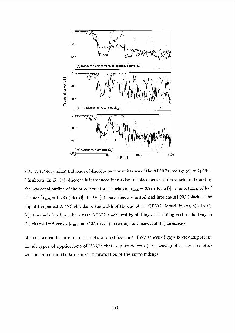
(b) Introduction of vacancies (D2)i L. —J I i 'i I
I 1 l__ —i I i_-J
0 500,
1000 1500f [kHz]
FIG. 7: (Color online) Influence of disorder on transmittance of the APNC's [red (gray)] of QPNC-
8 is shown. In D\ (a), disorder is introduced by random displacement vectors which are bound by
the octagonal outline of the projected atomic surfaces [o/max = 0.27 (dotted)] or an octagon of half
the size [«max — 0.135 (black)]. In D-i (b), vacancies are introduced into the APNC (black). The
gap of the perfect APNC shrinks to the width of the one of the QPNC [dotted, in (b),(c)]. In Ds
(c), the deviation from the square APNC is achieved by shifting of the tiling vertices halfway to
the closest PAS vertex [amax — 0.135 (black)], creating vacancies and displacements.
of this spectral feature under structural modifications. Robustness of gaps is very important
for all types of applications of PNC's that require defects (e.g., waveguides, cavities, etc.)
without affecting the transmission properties of the surroundings.
53
II. CLUSTERS AND SCALING OPERATIONS
A. Clusters and low-frequency dips
Cluster concepts for quasiperiodic structures arc based on the observation of ubiquitously
recurring structure motifs in electron microscopic images of quasicrystals. This idea is also
supported by tiling theory. Quasiperiodic structures can likewise be described by tilings
(i.e., tiles and matching rules) and coverings (i.e., clusters and overlapping rules). So far, we
have focused on the tiling description and therewith on the length scale of an edge length
or. For the 8-fold tiling, the length scale in a cluster description is illustrated in Fig. 2. A
quasilattice is shown, which is occupied by clusters whose innermost shells consist of close-
packed eight-rings (gray circles). This quasilattice [£glust (gray lines)] is related to the original
tiling [ts (black lines)] by scaling symmetry with the factor si — (v/2 + l)2. In phononics,
clusters should be defined either by their ability to support spatially confined resonance
modes (e.g., resonances in close-packed rings [23, 24]) or by their high local scatterer density,
which makes the cluster act as a larger joint-scattering object. Such close-packed structural
motifs are prominent especially in singular tilings.
The positions of band gaps formed by scattering at such eight-ring clusters can be es¬
timated by the gaps of an APNCcl,lst. The PAS of tfust is equivalently scaled by si and
the central frequency of the first APNCclust gap should be 1/si times that of the original
APNC. At these lower frequencies the scattering cross section of a single rod is rather small.
The waves encounter only an effective medium. For a gap to open up, the cluster must
mimic a larger scattering object, which scatters more strongly at low frequencies. At the
position of the expected APNCclust gap the spectrum of the QPNC-8 has no dip but reg¬
ular Fabry-Pérot oscillations (see arrow «i in Fig. 8). Thus, the local scatterer density of
the eight-ring clusters is not sufficient to act as an inhoinogeneity disturbing the effective
medium. However, if this scatterer density is modified by a replacement of the eight-ring by
a cylinder of the same radius (QPNC D4), this inhomogeneity can be accomplished. The
first gap in the spectrum of D4 opens at the position of the first band gap of the APNCclust.
In general, a PAS of fglust is also a PAS of f8 because the two structures are scaling symme¬
try equivalent. The equivalence of an s\ times larger PAS unit cell of tg [i.e., {(Ï101), (01Ï1)}]
and the main PAS [i.e., {(110Ï), (Olli)}] of an .si-times-scaled tiling is obvious. Thus, inter-
54
. _J 1_ I \J 1 _I .
0 100 200 300 400 500
f [kHz]
FIG. 8: (Color online) Transmittancc of QPNC-8 [red (gray)]. Arrows below the curves indicate
positions of the first gap of the original APNC scaled by S3 — 2cos(tt/8), S2 = \/2 + 1, and si — s^.
In transmittance of D\ (black) the disturbance of the effective medium by the larger rods leads to
an attenuation peak at the position of the first gap of the APNC for the quasilattice scaled by .sa.
esting structures for low-frequency gaps are defined by other pairs of strong Bragg peaks of
t% (at \k\ < l/oT) or equivalently by the original PAS and the scaling and rotoscaling factors
of the tiling. In Fig. 8, potential gap positions are indicated by arrows at positions of the
first gap of the original APNC inversely scaled by further scaling and rotoscaling factors of
*8 [s1 = 2cos(7r/8) and s2 — V2 +1]. The larger the scaling factor or the larger the unit cell
of the APNCclust, the larger is the required scattering strength of the cluster for the creation
of a significant gap.
B. Scaling symmetries
Regarding the global scaling symmetry of gap positions in transmittance, a very narrow
parameter space exists for structures exhibiting this special feature. Apart from that, general
mathematical restrictions (e.g., no strict self-similarity in structures with different scaling
factors) apply, as discussed by Velasco et al [12]. In one dimension, this scaling symmetry
can be quite distinct, as can be illustrated by a Fibonacci sequence of cpoxy sheets in water
(sheet thickness 0.2 mm, separations 1 and r mm). The gap positions in the spectrum are r-
scalablc and the individual bands arc self-similar with respect to their center [sec Fig. 9(a)].
This symmetry can be understood by imagining the sequence as a tight-binding system of
resonators (space between two sheets) of widths 1 and r. The ratio of their fundamental
resonance frequencies is r/1. Thus also the positions of the bands of coupled resonators
m
2,
<uo
c
to
"Ein
0
^A
-20
\f \
^0
ts,
55
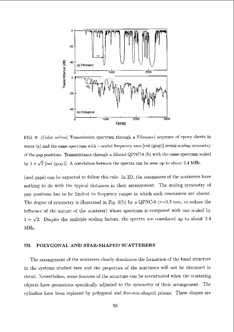
1000 2000
f [kHz]
3000
FIG. 9: (Color online) Transmission spectrum through a Fibonacci sequence of epoxy sheets in
water (a) and the same spectrum with r-scaled frequency axes [red (gray)] reveal scaling symmetry
of the gap positions. Transmittance through a diluted QPNC-8 (b) with the same spectrum scaled
by 1 + V2 [red (gray)]. A correlation between the spectra can be seen up to about 2.4 MHz.
(and gaps) can be expected to follow this rule. In 2D, the resonances of the scatterers have
nothing to do with the typical distances in their arrangement. The scaling symmetry of
gap positions has to be limited to frequency ranges in which such resonances are absent.
The degree of symmetry is illustrated in Fig. 9(b) by a QPNC-8 (r—0.3 mm, to reduce the
influence of the nature of the scatterer) whose spectrum is compared with one scaled by
1 + \/2. Despite the multiple scaling factors, the spectra are correlated up to about 2.4
MHz.
III. POLYGONAL AND STAR-SHAPED SCATTERERS
The arrangement of the scatterers clearly dominates the formation of the band structure
in the systems studied here and the properties of the scatterers will not be discussed in
detail. Nevertheless, some features of the structure can be accentuated when the scattering
objects have geometries specifically adjusted to the symmetry of their arrangement. The
cylinders have been replaced by polygonal and five-star-shaped prisms. These shapes are
56
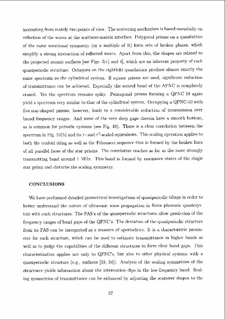
interesting from mainly two points of view. The scattering mechanism is based essentially on
reflection of the waves at the scatterer-matrix interface. Polygonal prisms on a quasilattice
of the same rotational symmetry (or a multiple of it) form sets of broken planes, which
simplify a strong interaction of reflected waves. Apart from this, the shapes are related to
the projected atomic surfaces [see Figs. 3(c) and 4], which are an inherent property of each
quasiperiodic structure. Octagons on the eightfold quasilattice produce almost exactly the
same spectrum as the cylindrical system. If squaie prisms are used, significant reduction
of transmittance can be achieved. Especially the second band of the APNC is completely
erased. Yet the spectrum remains spiky. Pentagonal prisms forming a QPNC-10 again
yield a spectrum very similar to that of the cylindrical system. Occupying a QPNC-10 with
five-star-shaped prisms, however, leads to a considerable reduction of transmission over
broad frequency ranges. And some of the very deep gaps therein have a smooth bottom,
as is common for periodic systems (see Fig. 10). There is a clear correlation between the
spectrum in Fig. 10(b) and its r- and r2-scaled equivalents. This scaling operation applies to
both the tenfold tiling as well as the Fibonacci sequence that is formed by the broken lines
of all parallel faces of the star prisms. The correlation reaches as far as the more strongly
transmitting band around 1 MHz. This band is formed by resonance states of the single
star prism and disturbs the scaling symmetry.
CONCLUSIONS
We have performed detailed geometrical investigations of quasiperiodic tilings in order to
better understand the nature of ultrasonic wave propagation in finite phononic quasicrys-
tals with such structures. The PAS's of the quasiperiodic structures allow prediction of the
frequency ranges of band gaps of the QPNC's. The deviation of the quasiperiodic structure
from its PAS can be interpreted as a measure of aperiodicity. It is a characteristic param¬
eter for each structure, which can be used to estimate transmittance in higher bands as
well as to judge the capabilities of the different structures to form clear band gaps. This
characterization applies not only to QPNC's, but also to other physical systems with a
quasiperiodic structure (e.g., surfaces [33, 34]). Analysis of the scaling symmetries of the
structures yields information about the attenuation dips in the low-frequency band. Scal¬
ing symmetries of transmittance can be enhanced by adjusting the scatterer shapes to the
57
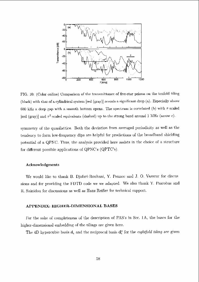
FIG. 10: (Color online) Comparison of the transmittance of five-star prisms on the tenfold tiling
(black) with that of a cylindrical system [red (gray)] reveals a significant drop (a). Especially above
600 kHz a deep gap with a smooth bottom opens. The spectrum is correlated (b) with r-scaled
[red (gray)] and T2-scaled equivalents (dashed) up to the strong band around 1 MHz (arrow c).
symmetry of the quasilattice. Both the deviation from averaged periodicity as well as the
tendency to form low-frequency dips are helpful for predictions of the broadband shielding
potential of a QPNC. Thus, the analysis provided here assists in the choice of a structure
for different possible applications of QPNC's (QPTC's).
Acknowledgments
We would like to thank B. Djafari-Rouhani, Y. Penncc and J. O. Vasseur for discus¬
sions and for providing the FDTD code we we adapted. We also thank Y. Psarobas and
R. Sainidou for discussions as well as Hans Reifler for technical support.
APPENDIX: HIGHER-DIMENSIONAL BASES
For the sake of completeness of the description of PAS's in Sec. I A, the bases for the
higher-dimensional embedding of the tilings are given here.
The 4D hypercubic basis dt and the reciprocal basis d* for the eightfold tiling are given
58
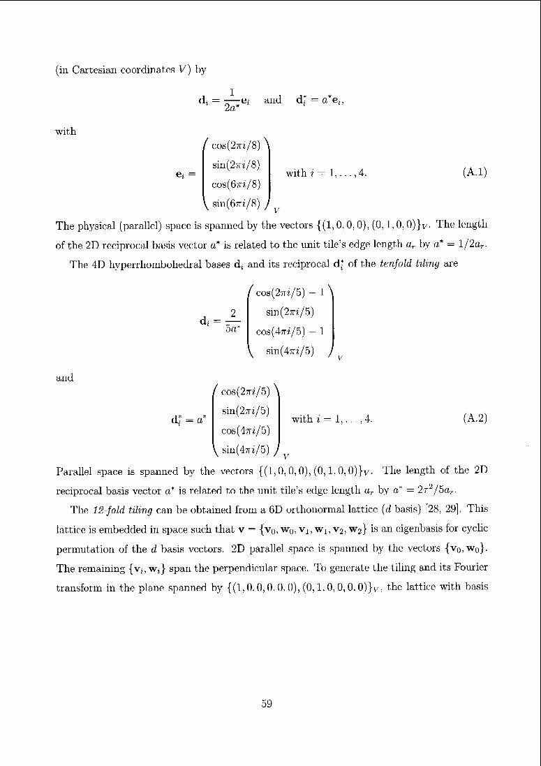
(in Cartesian coordinates V) by
d, — e, and2a*
with
e, = with i = 1, ,4. (A.1)
v
I cos(2ttz/8) \
sin(27T-i/8)
cos(67r?'/8)
\ sin(67rz/8) J
The physical (parallel) space is spanned by the vectors {(1,0, 0, 0), (0,1, 0, 0)}v. The length
of the 2D reciprocal basis vector a* is related to the unit tile's edge length aT by a* = l/2ar.
The 4D hyperrhombohedral bases dt and its reciprocal d* of the tenfold tiling are
/ cos(27ri/5) - 1 \
sin(27ri/5)
cos(47T?;/5) - 1
\ sin(47ri/5) /
d, = —5a*
with i = 1, (A.2)
v
and
/ cos(2ttz/5) \
sin(27ri/5)
cos(47n'/5)
\ sin(47rz/5) )
Parallel space is spanned by the vectors {(1,0,0,0), (0,1,0, ())}v The length of the 2D
reciprocal basis vector a* is related to the unit tile's edge length ar by a* — 2r2/5ar.
The 12-fold tiling can be obtained from a 6D orthonormal lattice (d basis) [28, 29], This
lattice is embedded in space such that v = {v0, w0, v1,w1,V2, w2} is an eigenbasis for cyclic
permutation of the d basis vectors. 2D parallel space is spanned by the vectors {v0,w0}.
The remaining {v„w,} span the perpendicular space. To generate the tiling and its Fourier
transform in the plane spanned by {(1, 0,0, 0, 0, 0), (0,1, 0, 0, 0, 0)}v, the lattice with basis
59
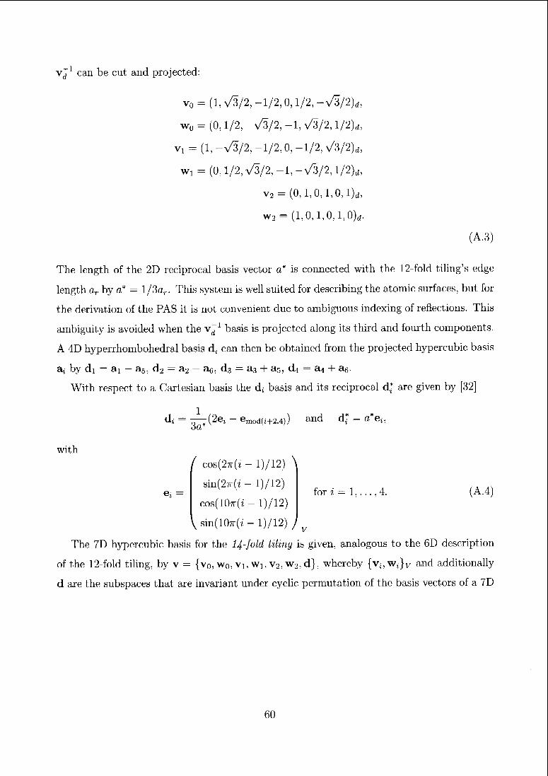
vd can be cut and projected:
v0 = (1, V3/2, -1/2, 0,1/2, - V3/2)d,
w0 - (0,1/2, -V3/2, -1, V3/2, l/2)d,
vi = (1, -A/2, -1/2, 0, -1/2, >/3/2)d)
wi - (Ü, 1/2, V3/2, -1, -n/3/2, l/2)d,
v2 = (0,l,0,l,0,l)d,
w2 = (1,0,1,0,1,0),.
(A.3)
The length of the 2D reciprocal basis vector a* is connected with the 12-fold tiling's edge
length ar by a* — l/3ar. This system is well suited for describing the atomic surfaces, but for
the derivation of the PAS it is not convenient due to ambiguous indexing of reflections. This
ambiguity is avoided when the v^1 basis is projected along its third and fourth components.
A 4D hyperrhombohedral basis d4 can then be obtained from the projected hypercubic basis
a^ by di = ai - a5, d2 = a2- a6, d3 = a3 + a5, d4 = a4 + a6.
With respect to a Cartesian basis the dt basis and its reciprocal d* are given by [32]
1
d* = ir^fäi —
em„d(i+2,4); and d* = a*eu
with
e, = for i = l, (A.4)
/ cos(2tt(z - 1)/12) \
sin(27r(i - 1)/12)
cos(10tt(z - 1)/12)
V sin(107r(/ - 1)/12) /
The 7D hypercubic basis for the 14-fold tiling is given, analogous to the 6D description
of the 12-fold tiling, by v = {v0, w0, vl5 Wi, v2, w2, d}, whereby {Vj,w,}y and additionally
d are the subspaces that are invariant under cyclic permutation of the basis vectors of a 7D
60
orthonormal lattice:
vo = (y/2/7(cos(27ri/7))7J=1)d,
w0 = (y/2/7(sm(2*i/7))7J=1)d,
vx = (y/2/7(cos(Airi/7))7J=1)d,
wi = (V2/7(svn(4iri/7))]=1)d,
v2 = {^2j7{œs^wij7))]=l)(h
w2 = (N/277(M/i(67ri/7));=1)d,
d= v^77(l, 1,1,1,1,1, l)d- (A.5)
The length of the 2D reciprocal basis vector a* is connected with the 14-fold tiling's edge
length ar by a* — 2/7ar.
IT
[9
[1«
[H
[12
[is;
[h:
E. Yablonovitch, Phys. Rev. Lett. 58, 2059 (1987).
http ://phys.lsu.edu/^jdowling/pbgbib.html
M. Sigalas, M.S. Kushwaha, E.N. Economou, M. Kafesaki, I.E. Psarobas and W. Stcurer,
Z. Kristallogr. 220, 765 (2005).
Y. Lai, Z.Q. Zhang, C.P Chan and L. Tsang, Phys. Rev. B 74, 054305 (2006).
D. Shechtman, I. Blech, D. Gratias and J.W. Cahn, Phys. Rev. Lett. 53, 1951 (1984).
R. Merlin, K. Bajema, R. Clarke, F.-Y. Juang and P.K. Bhattacharya, Phys. Rev. Lett. 55,
1768 (1985).
S. Ostlund and R. Pandit, Phys. Rev. B 29, 1394 (1984).
M. Kohmoto and B. Sutherland, Phys. Rev. B 34, 3849 (1986).
H. Tsunetsugu, T. Fujiwara, K. Ueda and T. Tokihiro, Phys. Rev. B 43, 8879 (1991).
M. Bertolotti, P. Masculli and C. Sibilia, Optics Letters 19, 777 (1994).
C. Sibilia, LS. Nefedov, M. Scalora and M. Bertolotti, J. Opt. Soc. Am. B 15, 1947 (1998).
V.R. Velasco, R. Perez-Alvarez and F. Garcia-Moliner, J. Phys.: Condens. Matter 14, 5933
(2002).
H. Aynaou, V.R. Velasco, A. Nougaoui, E.H. El Boudouti, B. Djafari-Rhouhani and D. Bria,
Surf. Sei. 538, 101 (2003).
Y.S. Chan, C.T. Chan and Z.Y. Liu, Phys. Rev. Lett. 80, 956 (1998).
61
[15] Y. Lai, X. Zhang and Z.Q. Zhang, J. Appl. Phys. 91, 6191 (2002).
[16] W. Man, M. Megens, P.J. Stcinhardt and P.M. Chaikin, Nature (London) 436, 993 (2005).
[17] M.E. Zoorob, M.D.B. Charlton, G.J. Parker, J.J. Baumberg and M.C. Netti, Nature (London)
404, 740 (2000).
[18] X. Zhang, Z.Q. Zhang and C.T. Chan, Phys. Rev. B 63, 081105(R) (2001).
[19] M. Hase, H. Miyazaki, M. Egashira, N. Shinya, K.M. Kojima and S.I. Uchida, Phys. Rev. B
66, 214205 (2002).
[20] M.A. Kaliteevski, S. Brand, R.A. Abram, T.F. Krauss, R. DeLa Rue and P. Millar, Nanotech-
nology 11, 274 (2000).
[21] D. Sutter and W. Steurer, Phys. Status Solidi C 1, 2716 (2004).
[22] S.P. Gorkhali, J. Qi and G.P. Crawford, J. Opt. Soc. Am. B 23, 149 (2006).
[23] Y. Wang, X. Hu, X. Xu, B. Cheng and D. Zhang, Phys. Rev. B 68, 165106 (2003).
[24] K. Wang, Phys. Rev. B 73, 235122 (2006).
[25] B. Djafari-Rouhani, Y. Pennée and J. O. Vasseur, (private communication).
[26] W. Steurer and T. Haibach, Acta. Crystallogr., Sect. A: Found. Crystallogr. 55, 48 (1999).
[27] A. Cervellino and W. Steurer, Acta. Crystallogr., Sect. A: Found. Crystallogr. 58, 180 (2002).
[28] J.E.S. Socolar, Phys. Rev. B 39, 10519 (1989).
[29] A. Yamamoto, Acta. Crystallogr., Sect. A: Found. Crystallogr. 52, 509 (1996).
[30] P. Repetowicz and J. Wolny, J. Phys. A 31, 6873 (1998).
[31] P. Shcng, Introduction to Wave Scattering, Localization and Mcsoscopic Phenomena, Aca¬
demic Press, San Diego (1995).
[32] W. Steurer, Z. Kristallogr. 219, 391 (2004).
[33] W. Steurer, Mat. Sei. Eng. 294, 268 (2000).
[34] Y. Weisskopf, S. Burkardt, M. Erbudak and J.-N. Longchamps, Surf. Sei., 601, 544 (2007).
62
Additional notes to article 5
The significance of strong Fourier coefficients
Wave propagation in a QPNC could be modeled by using a super-cell approach (i.e. an
approximant) and then apply the plane-wave-expansion method (see appendix B.l). In a
periodic structure the vectors of the reciprocal lattice readily designate; the Fourier coef¬
ficients important for the expansion. The same is true also for a quasiperiodic structure.
Just, these Fourier coefficients do not form a lattice. Thus, the strong Bragg-peaks can be
obtained straight forwardly from the Fourier transform and the question arises why the
simplification to the periodic average structure is necessary if the weighting of the coeffi¬
cients is known in advance? Certainly the physical quantities of a QPNC (e.g., its band
structured61 ) can be described by its stronger Fourier coefficients (which, by the way, are
often not that many). But the comparison of different structures according to a long list
of strong coefficients is not convenient. As the key parameters describing the degree of
aperiodicity, the occupancy, pocc, and the filling fraction of the PAS unit-cell, «f, seem
much more adequate. Alternatively, the ratio of the intensities of the Bragg-peaks used
to define a pseudo-Brillouin zone to the intensity of the \k\ — 0 peak could be studied.
Size dependence
The aperiodicity of quasiperiodic structures in general acts as a driving force for the lo¬
calization of waves. On the other hand, the scaling symmetry of these structures, being
a form of repetition (even though not a periodic one), pursues the formation of more
extended states. This fundamental competition has been identified early/1159 Now, ape¬
riodicity is effective in quasiperiodic systems of any size. The scaling symmetry, however,
is significant only in systems of a certain size;. Thus, the outcome of their competition is
quite crucially dependent on size.
This competition has many significant implications. Fist of all the size of the QPNC
becomes important for the interaction of waves. Finite QPNC's are likely to act like
disordered PNC's because the scaling-symmetry may require huge sections of a tiling to
be used. This may be a problem, because the chosen sections does not represent the whole
quasiperiodic structure. On the other hand, any application of QPNC's is doomed to use
such finite sections and therewith inherit only part of their properties.
The mean free path lengths, /inft„ can also be affected by this contest. If the disorder¬
like aperiodicity is favored by the chosen section, then /mfp is supposed to decrease and
if the scaling symmetry is pronounced it is supposed to increase. With decreasing Zmfp
wave propagation is expected to become more diffusion-like. And therewith, the spectral
features (e.g., bandgaps or defect states) lose their sensitivity to structural modifications
in their not to near surrounding because of their strongly limited range of coherency (see
63
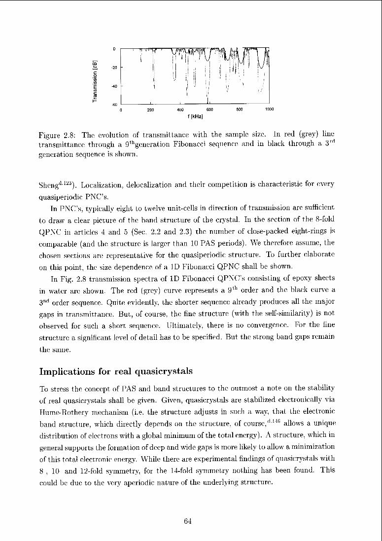
co
400 600
f [kHz]
1000
Figure 2.8: The evolution of transmittance with the sample size. In red (grey) line
transmittance through a 9thgeneration Fibonacci sequence and in black through a 3rd
generation sequence is shown.
Shengdm). Localization, delocalization and their competition is characteristic for every
quasiperiodic PNC's.
In PNC's, typically eight to twelve unit-cells in direction of transmission are sufficient
to draw a clear picture of the band structure of the crystal. In the section of the 8-fold
QPNC in articles 4 and 5 (Sec. 2.2 and 2.3) the number of close-packed eight-rings is
comparable (and the structure is larger than 10 PAS periods). We therefore assume, the
chosen sections are representative for the quasiperiodic structure. To further elaborate
on this point, the size dependence of a ID Fibonacci QPNC shall be shown.
In Fig. 2.8 transmission spectra of ID Fibonacci QPNC's consisting of epoxy sheets
in water are shown. The red (grey) curve represents a 9lh order and the black curve a
3nd order sequence. Quite evidently, the shorter sequence already produces all the major
gaps in transmittance. But, of course, the fine structure (with the self-similarity) is not
observed for such a short sequence. Ultimately, there is no convergence. For the fine
structure a significant level of detail has to be specified. But the strong band gaps remain
the same.
Implications for real quasicrystals
To stress the concept of PAS and band structures to the outmost a note on the stability
of real quasicrystals shall be given. Given, quasicrystals are stabilized electronically via
Hume-Rothery mechanism (i.e. the structure adjusts in such a way, that the electronic
band structure, which directly depends on the structure, of course,dl4(i allows a unique
distribution of electrons with a global minimum of the total energy). A structure, which in
general supports the formation of deep and wide gaps is more likely to allow a minimization
of this total electronic energy. While there are experimental findings of quasicrystals with
8-, 10- and 12-fold symmetry, for the 14-fold symmetry nothing has been found. This
could be due to the very aperiodic nature of the underlying structure.
64
2.4 Icosahedral phononic quasicrystals
D. Sutter,* P. Itten, P. Neves and W. Steurer
Laboratory of Crystallography, Department of Materials, ETH Zurich
(February 2, 2007)
Abstract
Periodic average structures (PAS) were found to assist the prediction of the band struc¬
tures of quasiperiodic phononic crystals (QPNC's) in two dimensions. In this first report
on a three-dimensional QPNC we present experimental transmission spectra of an icosa¬
hedral QPNC as well as a phononic crystal with its PAS. The transmission spectrum of
the QPNC features a very distinct band gap. This band gap agrees perfectly with the one
of the PNC in position and width. The suitability of the periodic average structure to
characterize; quasiperiodic structures and to estimate their physical properties is further
confirmed herewith.
'Electronic address: daniel. sutterOmat. ethz. ch
65
Research on quasiperiodic heterostructures has taken thirteen years (1985<i8' -1998d19)
to make the step from ID to 2D. And it took another eight years for the third dimension
(Man et al.AM). This leisurelincss in an otherwise fast developing field has many reasons
but mainly reflects the advances of production techniques for such structures on the
nanoscale (in photonics). Generally, investigations of 3D QPNCdG4, dM did not reveal
any physical properties, fundamentally different from those of 2D QPNC. Band gaps were
found in all systems but hard scattering regimes proved again to be more difficult for
obtaining clear bands and gaps.d-64 Nevertheless, then; are some interesting questions
regarding the distinctiveness of gaps or the tendency for wave-localization in 3D QPNC's.
Beyond this, of course, the fabrication of such systems is a challenging. Possible techniques
are the microwave stereolithography,d-8f) holographic methodsdii2 or inversion methods/177
This present study reports on the first 3D QPNC. The interpretation of the transmission
properties of the icosahedral QPNC (i-QPNC) is aided by using the periodic average
structure. This approach has been successfully applied to various 2D QPNC's before (see
Articles 4 and 5 in Sec. 2.2 and 2.3).
The icosahedral structure and its PAS
The icosahedral tiling,d78, d131or three-dimensional Penrose tiling has been frequently
used as a model quasilattice of real quasicrystals. While many different tilings have been
thoroughly analyzed in 2D, in 3D the icosahedral one is the very representative. For the
calculation of the vertices of the tiling we used the code by Janot,d-5/| which bases on the
higher-dimensional description (see appendix C). The 6D basis of the tiling (taken from
Steurer and Haibachd137) is given by
di1
2a*
/o\
0
1
0
0
V1/
and d, = —2a*
( sin0cos(27r?'/5) \sinÖsin(27rz/5)
cos/9
—sin0cos(47ri/5)
—sin0siii(47ri/5)—COS#
for i = 2, (2.G)
with 9 = 63.44° and a* = l/2ar (ar is the edge length of the unit building blocks).
The atomic surfaces are regular triacontahedra. Projection of the 6D lattice and the
triacontrahedra along the three directions (ïllulO)^, (OlIlOÏ)^, (Ï001Ï1)D onto parallel
G6
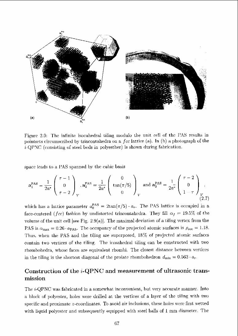
Figure 2.9: The infinite isocahedial tiling modulo the unit cell of the PAS results in
point&ets circumscribed by tiiacontahedra on a fee lattice (a). In (b) a photograph of the
z-QPNC (consisting of steel beds in polyesther) is shown during fabrication.
space leads to a PAS spanned by the cubic basis
1 \ / 0 \1
_...1
tan(7r/5)„pas_
„PAS_
An —
2a~*\ 0
and a?AS =
/
2a*
which has a lattice parameter a£AS = 2tan(7r/5) • ar. The PAS lattice is occupied in a
face-centered (fee) fashion by undistorted triacontahedra. They fill af = 19.5%) of the
volume of the unit cell [see Fig. 2.9(a)]. The maximal deviation of a tiling vertex from the
PAS is amax = 0.26 • aPAS. The occupancy of the projected atomic surfaces is pocc — 1.18.
Thus, when the PAS and the tiling are supeiposed, 18% of projected atomic surfaces
contain two veitices of the tiling. The icosahedral tiling can be constructed with two
rhombohedra, whose faces are equivalent rhombi. The closest distance between vertices
in the tiling is the shortest diagonal of the prolate rhombohedron dmm — 0.563 • a,
Construction of the z-QPNC and measurement of ultrasonic trans¬
mission
The 7-QPNC was fabricated in a somewhat inconvenient, but very accurate manner. Into
a block of polyester, holes were drilled at the vertices of a layer of the tiling with two
specific and proximate1 z-coordinates. To avoid air inclusions, these holes were first wetted
with liquid polyester and subsequently equipped with steel balls of 1 mm diametei. The
67
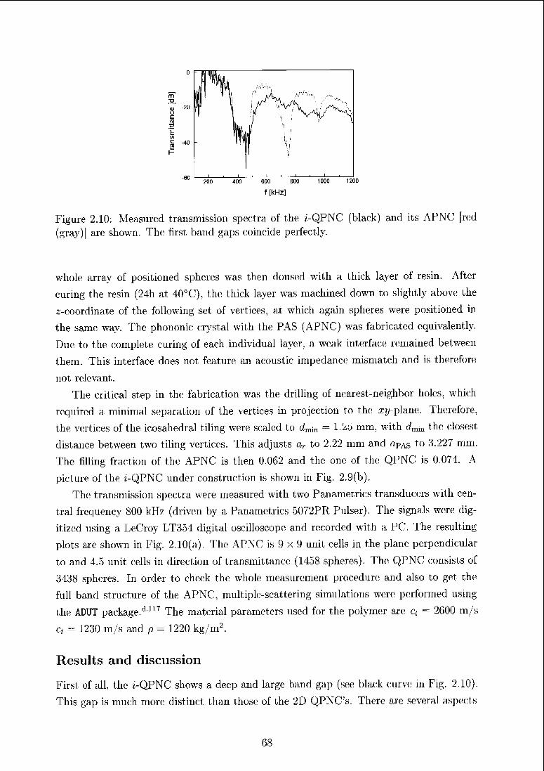
0
m
f 20
SE(A
200 400 600 800 1000 1200
f [kHz]
Figure 2.10: Measured transmission spectra of the ?-QPNC (black) and its APNC [red
(gray)] arc shown. The first band gaps coincide perfectly.
whole array of positioned spheres was then doused with a thick layer of resin. After
curing the resin (24h at 40°C), the thick layer was machined down to slightly above the
z-coordinate of the following set of vertices, at which again spheres were positioned in
the same1 way. The phononic eiystal with the PAS (APNC) was fabricated equivalently.
Due to the complete curing of each individual layer, a weak interface remained between
them. This interface does not feature an acoustic impedance mismatch and is therefore
not relevant.
The critical step in the fabrication was the drilling of nearest-neighbor holes, which
required a minimal separation of the vertices in projection to the1 xy-planc. Therefore,
the vertices of the icosahedral tiling were scaled to dmm — 1 'zo mm, with dmm the closest
distance between two tiling vertices. This adjusts ar to 2.22 mm and «pas to 3.227 mm.
The filling fraction of the APNC is then 0.062 and the one of the QPNC is 0.074. A
picture of the ?-QPNC under construction is shown in Fig. 2.9(b).
The transmission spectra were measured with two Panametrics transducers with cen¬
tral frequency 800 kHz (driven by a Panametrics 5072PR Puiser). The signals were dig¬
itized using a LeCioy LT354 digital oscilloscope and recorded with a PC. The resulting
plots are shown in Fig. 2.10(a). The APNC is 9 x 9 unit cells in the plane perpendiculai
to and 4.5 unit cells in direction of transmittance (1458 spheres). The QPNC consists of
3438 spheres. In ordei to check the whole measurement procedure and also to get the
full band structure of the APNC, multiple-scattering simulations were performed using
the ADUT package/1 m The material parameters used for the polymer are q = 2000 m/s
ct = 1230 m/s and p = 1220 kg/m2.
Results and discussion
First of all, the i-QPNC shows a deep and large band gap (see black curve1 in Fig. 2.10).
This gap is much moie distinct than those of the 2D QPNC's. There are several aspects
1 _j I i 1 ] L
68
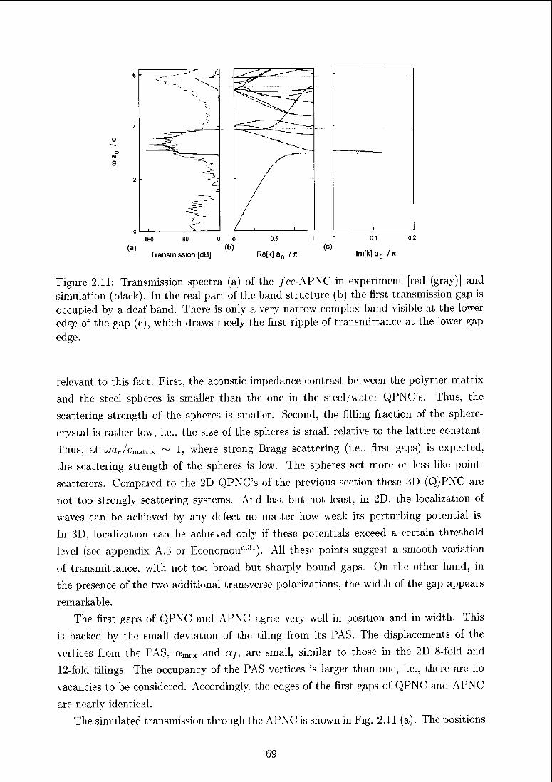
ü
o
(D
3
0
.160 -80 0 0 0.5 10 0.1 0.2
(a) (b) (c)Transmission [dB] Re[k]a0 In lm[k]a0 /jt
Figure 2.11: Transmission spectra (a) of the; /cc-APNC in experiment [red (gray)l and
simulation (black). In the; real part of the band structure (b) the first transmission gap is
occupied by a deaf band. There is only a very narrow complex band visible at the lower
edge of the gap (c), which draws nicely the first ripple of transmittance at the lower gap
edge.
relevant to this fact. First, the acoustic impedance contrast between the polymer matrix
and the steel spheres is smaller than the one in the steel/water QPNC's. Thus, the
scattering strength of the spheres is smaller. Second, the filling fraction of the sphere-
crystal is rather low, i.e., the size of the spheres is small relative to the lattice constant.
Thus, at oxZr/Cmatrix ~ 1, where strong Bragg scattering (i.e., first gaps) is expected,
the scattering strength of the spheres is low. Tin; spheres act more or less like point-
scatterers. Compared to the 2D QPNC's of the previous section these 3D (Q)PNC are
not too strongly scattering systems. And last but not least, in 2D, the localization of
waves can be achieved by any defect no matter how weak its perturbing potential is.
In 3D, localization can be achieved only if these potentials exceed a certain threshold
level (see appendix A.3 or Economou'131). All these points suggest a smooth variation
of transmittance, with not too broad but sharply bound gaps. On the other hand, in
the presence of the two additional transverse polarizations, the width of the gap appears
remarkable.
The first gaps of QPNC and APNC agree very well in position and in width. This
is backed by the small deviation of the tiling from its PAS. The displacements of the
vertices from the PAS, amax and a/, are small, similar to those in the 2D 8-fold and
12-fold tilings. The occupancy of the PAS vertices is larger than one, i.e., there are no
vacancies to be considered. Accordingly, the edges of the first gaps of QPNC and APNC
are nearly identical.
The simulated transmission through the APNC is shown in Fig. 2.11 (a). The positions
69
-
.__.- -JW
- ^_j~" -
—s--*
~~^~>e^___
-*
-
^
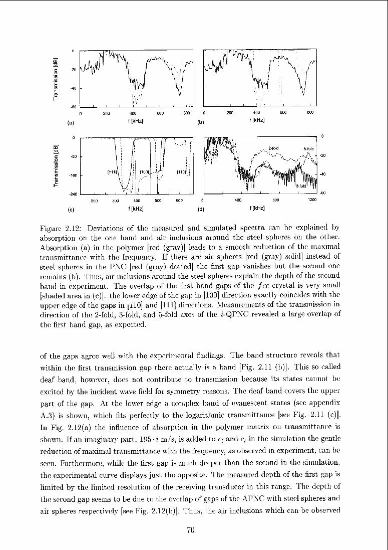
CD
TJ.
m
c
g
-160 -
I ' fII 1Il II
! il
^vx
1
1
1
1
1
jï)/ilII
! '
I !1 '
1 III '
II II
[mil ! /!\ i / i
[100],
l
1
1
1 [110]! !
\
I ' I 1
(c)
«1rV'
liF 11!"
H"Vi t
^/Jv
2-fold 5-fold
Ai
'
it* %
i
111
i 1 '3-fold
' '"||
300 400 500
f [kHz]
o
(d)
400 800
f [kHz]
-40
Figure 2.12: Deviations of the measured and simulated spectra can be explained by
absorption on the one hand and air inclusions around the steel spheres on the other.
Absorption (a) in the polymer [red (gray)] leads to a smooth reduction of the maximal
transmittance with the frequency. If there are air spheres [red (gray) solid] instead of
steel spheres in the PNC [red (gray) dotted] the first gap vanishes but the second one
remains (b). Thus, air inclusions around the steel spheres explain the depth of the second
band in experiment. The overlap of the first band gaps of the fee crystal is very small
[shaded area in (c)]. the lower edge of the gap in [100] direction exactly coincides with the
upper edge of the gaps in [il0] and [111] directions. Measurements of the transmission in
direction of the 2-fold, 3-fold, and 5-fold axes of the i-QPNC revealed a large overlap of
the first band gap, as expected.
of the gaps agree well with the experimental findings. The band structure reveals that
within the first transmission gap there actually is a band [Fig. 2.11 (b)]. This so called
deaf band, however, does not contribute to transmission because its states cannot be
excited by the incident wave field for symmetry reasons. The deaf band covers the upper
part of the gap. At the lower edge a complex band of evanescent states (see appendix
A.3) is shown, which fits perfectly to the logarithmic transmittance [see Fig. 2.11 (c)[.
In Fig. 2.12(a) the influence of absorption in the polymer matrix on transmittance is
shown. If an imaginary part, 195 i m/s, is added to q and ct in the simulation the gentle
reduction of maximal transmittance with the frequency, as observed in experiment, can be
seen. Furthermore, while the first gap is much deeper than the second in the simulation,
the experimental curve displays just the; opposite. The measured depth of the first gap is
limited by the limited resolution of the receiving transducer in this range. The depth of
the second gap seems to be due to the overlap of gaps of the APNC with steel spheres and
air spheres respectively [see Fig. 2.12(b)], Thus, the air inclusions which can be observed70
around a small fraction of spheres should support formation of a deep second gap and the
first one is underestimated due to lack of better resolution. Absorption, air inclusions as
well as limitations of the experimental setup can be expected to affect transniittance of
the i-QPNC in the same way. The isotropy of transmission of the two PNC's differs very
decisively. While the first band gap of the APNC in directions of the 2-fold and 3-fold
axes does not overlap with that along the 4-fold axes at all a narrow omnidirectional gap
opens at the upper edge of the latter [Fig. 2.12(c)]. The measurements of transmission in
different directions of the z-QPNC is rather difficult due to the oblique angle of incidence
on the sample in all but one direction. Nevertheless, along the 3-fold and 5-fold axes the
first gaps are even larger and coincide very well with the gap measured in direction of the
2-fold axes [Fig. 2.12(d)].
Conclusions
The investigation of an icosahedral phononic quasicrystal has shown that the periodic av¬
erage structure is very helpful for the prediction of physical properties of 3D quasiperiodic
systems. 3D QPNC's (QPTC's) have hardly been treated so far. The clear focus on 2D
structures can be justified by the potential applications especially of photonic quasicrys-
tals in optical devices, which ultimately are supposed to constitute the optical computer.
In optical devices the typical architectures are still planar. With increasing degree of
integration, however, the need for 3D QPTC's could arise1. More generally, 3D QPNC's
and QPTC's can be expected to act more similar to their periodic counterparts because
of the reduced tendency of wave-localization as well as the lower filling fractions. This
could ease working with such structures.
71
2.5 QPNC's and clusters (Article 2)
The following reprinted article deals in more detail with QPNC-10's based on Penrose
tilings with different decorations. The occurrence of close-packed ten rings is very different
in these; patterns. The influence of these rings on the formation of band gaps as well as
on the localization behavior of the waves is discussed.
D. Sutter and W. Steurer, Phys. Status Solidi C 1, 2716 (2004).
72
phys. stat. sol. (c) 1, No. 11, 2716-2719 (2004) / DOI 10.1002/pssc.2004Q5398
Ultrasonic investigation of phononic Penrose crystals
Daniel Sutter* and Walter Steurer
Laboratory of Crystallography, ETH Zurich, Wolfgang-Pauli-Strasse 10, 8093 Zurich, Switzerland
Received 15 July 2004, revised 9 August 2004, accepted 27 September 2004
Published online 17 November 2004
PACS 43.40.Cw, 62.30.+d, 71.23.Ft
This article reports on experimental ultrasound studies of two-dimensional phononic quasicrystals consist¬
ing of steel rods submerged in water. The arrangements follow Penrose tilings with different decorations.
Transmission spectra reveal no gaps indicating band gaps in the system, however, characteristic dips were
found for the different arrangements. Three tilings were considered. Two of them have the same unit-tiles
(same short range order), two of them the same arrangement (same long range order). In order to investi¬
gate the contributions of local arrangements to the spectral properties of the whole structure, several clus¬
ter motifs and rectangular subsections of the phononic quasicrystals were studied.
© 2004 WILEY-VCH Verlag GmbH & Co. KüaA, Weinheim
1 Introduction
In the last ten years a new interest in elastic wave propagation and localization has been prompted by
investigations of phononic crystals. Conventional (periodic) structures of this type have been investi¬
gated extensively, and the first steps towards quasiperiodic structures in one and two dimensions have
been reported (e.g. Velasco e* al. [1], Lai et al. [2] and Suiter et al. |3J). Apart from these, several papers
on photonic quasicrystals have been published [4, 5]. Zoorob et al. [6] and Bayindir et al. [7] have found
manifestations of bandgaps in transmittance measurements of their photonic structures experimentally.
Most of the published data concerns bandstructures with large gaps, which are of widths and depths
comparable to those of periodic structures. Others report on structures featuring no gaps but only de¬
pleted regions in the density of states [5]. The question as to whether or not there are gaps in bandstruc¬
tures of photonic quasicrystals is therefore positively answered. What remains is to categorize the struc¬
tures according to the existence of bandgaps and to investigate the mechanisms, which create them. Sev¬
eral proposals that address the question of possible mechanisms have already been made in literature on
photonic quasicrystals. The seminal work of Chan et al. [4] contained some of them. They investigated
the dependence of the transmittance on the extension of the crystal sample and found that the spectral
gaps can be found in rather small subsections of a structure. Their conclusion was that local scattering is
governing the formation of bandgaps rather than global scattering and that therefore long-range periodic
order is not a prerequisite for the existence of a gap (see also Hase et al. [8]). Wang et al. [9] then dis¬
covered, that there are sharp peaks in transmittance spectra of defect-free photonic quasicrystals, which
are associated with modes strictly localized at singularities in the structure. It was suggested that these
modes propagate via hopping from one singularity to another. The density and distribution of such po¬
tential sites for wave localization were found to have a strong effect on transmittance properties.
The first published work on two-dimensional phononic quasicrystals (Lai et al. [2]) did not go this far,
and only reported on the existence of gaps in the bandstructure of the investigated quasiperiodic square
triangle tiling. To our knowledge, no-one outside our group [3], has yet performed according experi-
"
Corresponding author: e-mail: [email protected] ,Phone: +41 1 632 37 27, Fax: +41 1 632 11 33
» 2004 WILEY-VCH Verlag GmbH & Co. KGaA, Wcinhdm
73
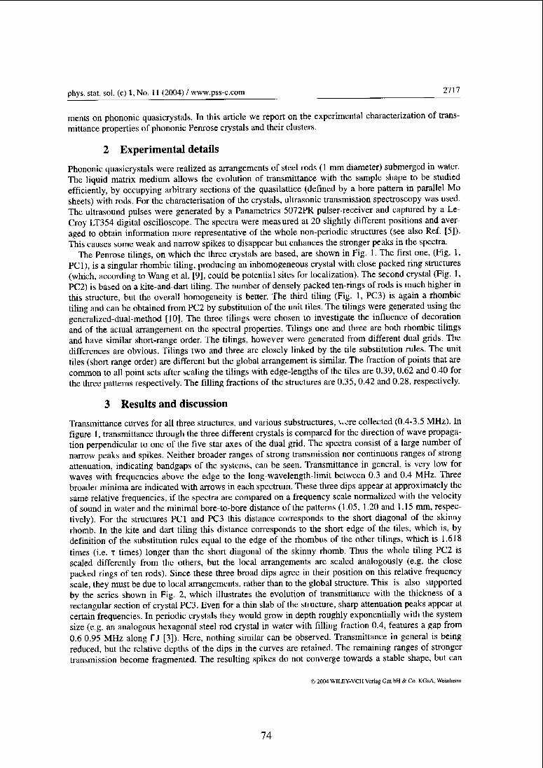
phys. stat. sol. (c) 1, No. 11 (2004) / www.pss-c.com2717
ments on phononic quasicrystals. In this article we report on the experimental characterization of trans¬
mittance properties of phononic Penrose crystals and their clusters.
2 Experimental details
Phononic quasicrystals were realized as arrangements of steel rods (1 mm diameter) submerged in water.
The liquid matrix medium allows the evolution of transmittance with the sample shape to be studied
efficiently, by occupying arbitrary sections of the quasilatlice (defined by a bore pattern in parallel Mo
sheets) with rods. For the characterisation of the crystals, ultrasonic transmission spectroscopy was used.
The ultrasound pulses were generated by a Panametrics 5072PR pulser-receiver and captured by a Le-
Croy LT354 digital oscilloscope. The spectra were measured al 20 slightly different positions and aver¬
aged to obtain information more representative of the whole non-periodic structures (see also Ref. [5]).
This causes some weak and narrow spikes to disappear but enhances the stronger peaks in the spectra.
The Penrose tilings, on which the three crystals are based, are shown in Fig. 1. The first one, (Fig. 1,
PCI), is a singular rhombic tiling, producing an inhomogeneous crystal with close packed ring structures
(which, according to Wang et al. [9], could be potential sites for localization). The second crystal (Fig. 1,
PC2) is based on a kite-and-dart tiling. The number of densely packed ten-rings of rods is much higher in
this structure, but the overall homogeneity is better. The third tiling (Fig. 1, PC3) is again a rhombic
tiling and can be obtained from PC2 by substitution of the unit tiles. The tilings were generated using the
generalized-dual-method [10]. The three tilings were chosen to investigate the influence of decoration
and of the actual arrangement on the spectral properties. Tilings one and three are both rhombic tilings
and have similar short-range order. The tilings, however were generated from different dual grids. The
differences are obvious. Tilings two and three are closely linked by the tile substitution rules. The unit
tiles (short range order) are different but the global arrangement is similar. The fraction of points that are
common to all point sets after scaling the tilings with edge-lengths of the tiles are 0.39, 0.62 and 0.40 for
the three patterns respectively. The filling fractions of the structures are 0.35,0.42 and 0.28, respectively.
3 Results and discussion
Transmittance curves for all three structures, and various substructures, \,ere collected (0.4-3.5 MHz). In
figure 1, transmittance through the three different crystals is compared for the direction of wave propaga¬
tion perpendicular to one of the five star axes of the dual grid. The spectra consist of a large number of
narrow peaks and spikes. Neither broader ranges of strong transmission nor continuous ranges of strong
attenuation, indicating bandgaps of the systems, can be seen. Transmittance in general, is very low for
waves with frequencies above the edge to the long-wavelength-limil between 0.3 and 0.4 MHz. Three
broader minima are indicated with arrows in each spectrum. These three dips appear at approximately the
same relative frequencies, if the spectra are compared on a frequency scale normalized with the velocity
of sound in water and the minimal bore-to-bore distance of the patterns (1.05, 1.20 and 1.15 mm, respec¬
tively). For the structures PCI and PC3 this distance corresponds to the short diagonal of the skinny
rhomb. In the kite and dart tiling this distance corresponds to the short edge of the tiles, which is, by
definition of the substitution rules equal to the edge of the rhombus of the other tilings, which is 1.618
times (i.e. t times) longer than the short diagonal of the skinny rhomb. Thus the whole tiling PC2 is
scaled differently from the others, but the local arrangements are scaled analogously (e.g. the close
packed rings of ten rods). Since these three broad dips agree in their position on this relative frequency
scale, they must be due to local arrangements, rather than to the global structure. This is also supported
by the series shown in Fig. 2, which illustrates the evolution of transmittance with the thickness of a
rectangular section of crystal PC3. Even for a thin slab of the structure, sharp attenuation peaks appear at
certain frequencies. In periodic crystals they would grow in depth roughly exponentially with the system
size (e.g. an analogous hexagonal steel rod crystal in water with filling fraction 0.4, features a gap from
0.6-0.95 MHz along l~J [3]). Here, nothing similar can be observed. Transmittance in general is being
reduced, but the relative depths of the dips in the curves are retained. The remaining ranges of stronger
transmission become fragmented. The resulting spikes do not converge towards a stable shape, but can
© 2004 WII.EY-VCH Verlag Cm bH & Co. KGaA, Weinheira
74
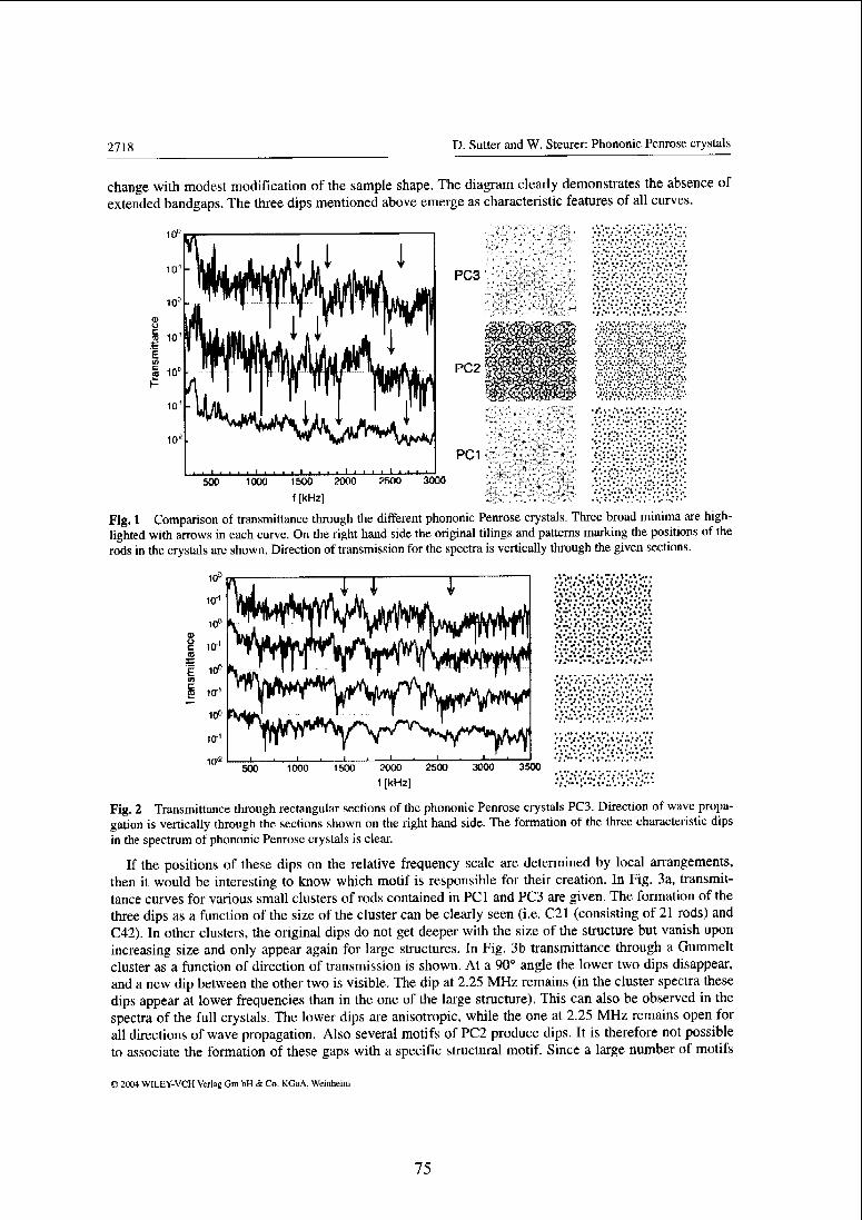
2718 D. Sutter and W. Steurer: Phononic Penrose crystals
change with modest modification of the sample shape. The diagram clearly demonstrates the absence of
extended bandgaps. The three dips mentioned above emerge as characteristic features of all curves.
PC3
*"^**W»mUPC2
PC1
soo 1000 15O0
f [kHz]
2O00 2500 3000
Fig. 1 Comparison of transmittance through the different phononic Penrose crystals. Three broad minima are high¬
lighted with arrows in each curve. On the right hand side the original tilings and patterns marking the positions of the
rods in the crystals arc shown. Direction of transmission for the spectra is vertically through the given sections.
.•."•vi-'.v;;
ra 10-
Vi-.V
3500
Fig. 2 Transmittance through rectangular sections of the phononic Penrose crystals PC3. Direction of wave propa¬
gation is vertically through the sections shown on the right hand side. The formation of the three characteristic dips
in the spectrum of phononic Penrose crystals is clear.
If the positions of these dips on the relative frequency scale are determined by local arrangements,
then it would be interesting to know which motif is responsible for their creation. In Fig. 3a, transmit¬
tance curves for various small clusters of rods contained in PCI and PC3 are given. The formation of the
three dips as a function of the size of the cluster can be clearly seen (i.e. C21 (consisting of 21 rods) and
CAT). In other clusters, the original dips do not get deeper with the size of the structure but vanish upon
increasing size and only appear again for large structures. In Fig. 3b transmittance through a Gummelt
cluster as a function of direction of transmission is shown. At a 90° angle the lower two dips disappear,
and a new dip between the other two is visible. The dip at 2.25 MHz remains (in the cluster spectra these
dips appear at lower frequencies than in the one of the large structure). This can also be observed in the
spectra of the full crystals. The lower dips are anisotropic, while the one at 2.25 MHz remains open for
all directions of wave propagation. Also several motifs of PC2 produce dips. It is therefore not possible
to associate the formation of these gaps with a specific structural motif. Since a large number of motifs
O 2004 WILLY-VtH Verlag dm hH & Co KGaA, Weinheim
75

phys. stat. sol. (c) 1, No. 11 (2004) / www.pss-c.com2719
seem to produce these spectral features, the question arises as to whether the very fundamental unit tiles
(i.e. the rhombus, kites and darts) are sufficient to determine the position of the dips on the frequency
scale. This question could be pursued further by studying the periodic approximanl structures of these
unit-tiles experimentally.
i . i i i I L, il- i J i . II « Ulli ill
500 1000 1500 2000 2500 3000 500 10O0 1500 2000 2500 3000
f [kHz] f [kHz]
Fig. 3 In diagram a, the formation of the three dips for PC 1 and its clusters is clearly present. In diagram b, trans-
mittance through PC3 and its clusters are shown. The formation of the lower two of the dips can be observed (grey
bars). There are also indications of the dip at the highest frequency of the three, but they are shifted to lower fre¬
quencies. The topmost curve (taken at 18°) also exhibits a peak there (isotropic dip), whereas the lower ones arc
replaced by a single minimum between the others (anisotropic dip).
The crystals PCI and PC2 contain very close packed clusters (e.g. featuring CI 1), which appear to the
eye as inhomogeneities (see Fig. 2). Such motifs have been identified as those responsible for localized
modes in photonic structures (see Wang et al. [9]). PC3, in contrast, consists of a rather homogeneous
arrangement of rods. The fact, that the lower dips are obscured by sharp peaks for large samples of PC2
could be connected with the presence of coupled, localized modes propagating from one such cluster to
the other. Further clarification of this suggestion should emerge from theoretical calculations.
4 Conclusions and outlook
We have shown the transmission properties of different phononic Penrose crystals. No clear evidence of
bandgaps was found but all of them exhibit broad dips in the spectra at the same relative frequencies
(normalized with minimal bore-to-bore distance of the patterns). Some dips are anisotropic and one is
isotropic. The same dips were found in transmittance curves of several clusters of the crystals featuring
the same anisotropic behaviour. The structures of the different clusters creating the characteristic dips are
quite different. A further localization of the origin of these dips will be attempted by calculating the
displacement field maps und by experimental studies of periodic approximants.
References
[1] V. R. Velasco and J. E. Zàrate, Prog. Surf. Sei. 67, 383 (2001).
[2] Y. Lai, X. Zhang, and Y. Q. Zhang, J. Appl. Phys. 91, 6191 (2002).
[3] D. Sutter, G. Krauss, and W. Steurer, Mater. Res. Soc. Symp. Proc. 805, 99 (2004).
[4] Y. S. Chan, C. T. Chan, and Z. Y. Liu, Phys. Rev. Lett. 80, 956 (1998).
[5] M. A. Kalitevski, S. Brand, R. A. Abram, T. F. Krauss, R. De La Rue, and P. Millar, Nanotechnology 11, 274
(2000).
[6] M. E. Zoorob, M. D. B. Charlton, G. J. Parker, J. J. Baumberg, and M. C. Netti, Nature 404, 740 (2000).
[7] M. Bayindir, E. Cubukcu, I. Bulu, and E. Ozbay, Europhys. Lett. 56, 41 (2001).
[8] M. Hase, H. Miyasaki, M Egashira, N. Shinya, K. M. Kqjima, and S. Uchida, Phys. Rev. B 66, 214205 (2002).
[9] Y. Wang, X. Hu, X. Xu, B. Cheng, and D. Zhang, Phys. Rev. B 68, 165106 (2003).
[10] G. G. Naumis and J. L. Aragon, Z. Kristallogr. 218, 397 (2003).
© 2004 WILEY-VCH Verlag Gm bH & Co. KGaA, Wcmheim
76
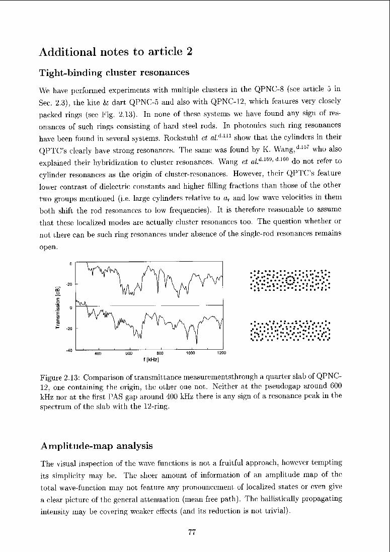
Additional notes to article 2
Tight-binding cluster resonances
We have performed experiments with multiple clusters in the QPNC-8 (see article 5 in
Sec. 2.3), the kite & dart QPNC-5 and also with QPNC-12, which features very closely
packed rings (see Fig. 2.13). In none of these systems we have found any sign of res¬
onances of such rings consisting of hard steel rods. In photonics such ring resonances
have been found in several systems. Rockstuhl et al.lLln show that the cylinders in their
QPTC's clearly have strong resonances. The same was found by K. Wang,d-157 who also
explained their hybridization to cluster resonances. Wang et fli.fL159' d,16° do not refer to
cylinder resonances as the origin of cluster-resonances. However, their QPTC's feature
lower contrast of dielectric constants and higher filling fractions than those of the other
two groups mentioned (i.e. large cylinders relative to ar and low wave velocities in them
both shift the rod resonances to low frequencies). It is therefore reasonable to assume
that these localized modes are actually cluster resonances too. The question whether or
not there can be such ring resonances under absence of the single-rod resonances remains
open.
.40 I u__- 1 . —I i 1 J 1- ' '
400 600 800 1000 1200
f [kHz]
Figure 2.13: Comparison of transmittance measurementsthrough a quarter slab of QPNC-
12, one containing the origin, the other one not. Neither at the pseudogap around 600
kHz nor at the first PAS gap around 400 kHz there is any sign of a resonance peak in the
spectrum of the slab with the 12-ring.
Amplitude-map analysis
The visual inspection of the wave functions is not a fruitful approach, however tempting
its simplicity may be. The sheer amount of information of an amplitude map of the
total wave-function may not feature any pronouncement of localized states or even give
a clear picture of the general attenuation (mean free path). The ballistically propagating
intensity may be covering weaker effects (and its reduction is not trivial).
77
Chapter 3
Synthesis
From the discussions in the preceding articles we want to draw four major conclusions
and propose issues for further investigations.
Major conclusions (recommendations)
1. in resonance-based systems, quasiperiodic structures are very favorable. Their ro¬
tational symmetry clearly induces isotropic transmission properties. Bands and
gaps form analogous to those in PNC's just more isotropic. We have identified no
draw-back for using a QPNC-14 for the fabrication of an acoustic or optical de¬
vice. However, already the 8-fold tiling produces an almost completely isotropic
first bandgap. Higher rotational symmetries are only necessary to achieve the same
for the higher gaps.
2. in strongly scattering systems without resonances, on the other hand, quasiperiodic
structurels seem less favorable. Among all quasiperiodic structures analyzed, the
most periodic one (on average), QPNC-8, produces the clearest spectral features.
Given the constraint of a high-contrast materials combination for the construction
of a QPNC- or QPTC-based device, a maximization of isotropic transmission prop¬
erties can be achieved only at the expense of clear bands and gaps.
3. especially in such cases the periodic average structures (PAS) of the quasiperiodic
tiling is very helpful tool for the prediction of physical properties of quasiperiodic
systems. This approach is applicable to all quasiperiodic structures and since it
is based on Bragg scattering its validity restricted to QPNC's (QPTC's) without
strong resonances of the single scattering.
4. SD Bragg-scattering QPNC's seem to be very convenient to work with. Because
they generally have lower filling fractions and because 3D waves are intrinsically
less prone to undergo localization, 3D QPNC's can be expected to act more similar
to PNC's and produce less chaotic transmission spectra than 2D QPNC's do.
78
Proposals
1. Experimentally, a very helpful thing to do is to measure the mean free path of
wave propagation. As discussed in Sec. A.3 this requires spatially resolved intensity
measurements.d8ü Such experiments could shed more light to the propagation of
critically localized waves in QPNC's (see Delia Villa et al.d-25).
2. Computationally, a revision of the FDTD-code implementing advanced meshing
techniques would provide the basis for the investigation of far larger samples. In¬
vestigations of large samples would favor the influence of the scaling symmetry of
quasiperiodic structures in its contest against aperiodicity.
3. With respect to applications, searching for strong resonators usable for QPNC's is
of prime importance in the light of the above recommendations.
79
Appendix A
Theory of elastic waves
In this first appendix the general theory of clastic waves and their propagation are sum¬
marized. The fundamental elastic wave equation will be discussed as well as the scattering
from solid rods in liquid hosts (Sec. A.2). Finally typical tiansmission and attenuation
legimes (types of wave functions) will be analyzed (Sec. A.3). The subsequent chapter
will then show, how this is all treated by the different computational methods (Sec. B).
A.l The wave-equation
In this section we derive the elastic wave-equation for non-homogeneous systems.tiM'a °
By non-homogeneous we understand a composite of volumes of homogeneous elastic bod¬
ies. The volumes of these1 homogeneous regions arc large in phononic crystals and therefore
there is no need to consider any aspect of atomicity. The wave-equation links the spa¬
tial distribution and the temporal evolution of the elastic stress and the elastic strain in
the materials and along their interfaces. The interaction of stress and strain govern the
propagation of elastic waves. The wave functions solving the wave-equation contain all
information about the interesting propeities of a phononic crystal (e.g., transmittance,
dispersion, local amplitude distributions etc.).
The wave-equation is a simple combination of Newton's law of motion and Hooke's
law. The tensor of the elastic tension oi stress er (present at a certain point in the system
r at a ceitain time t) is given byAF
.= - (A,)
a directed foice AF acting on an area element a with normal vector n. This area clement
then suffers the tension
/ orjnx + axyny + a^znz
(A.2)
80
The stresses on all faces of a volume element exert a total force F on it
F= [ ada. (A.3)Ja
Using the Gaussian theorem F transfers to
F% = J (alxnx + aiyny + alznz)da = J (-^ + -^ + -£f)dV. (A.4)
According to Newton's law of motion the net force F, resulting from the stresses at all
faces, accelerates the movement ù of a volume element dV about its initial position
F, = / pihdV (A.5)Jv
and therewith
/^ +^ + ^y (A6)V ox ay oz J
The stress tensor a is related to the strain tensor £ via Hooke's law
(Tij — 2_^ CijklEkl (A-7)
and e can be defined by the spatial derivatives of u (assuming small, elastic displacements,
i.e. neglecting second order terms)
£ki —1 /duk
,
duil^ + F-). (A-8)\OXl
ax* /2 VUX{ U£h
The tensor C relating stress and strain is called the elastic stiffness tensor and is of
fourth rank. In crystalline materials it induces the symmetry of the structure to the
physical property stress, it is then anisotropic and can have maximally 21 independent
parameters (triclinic crystal systems). For isotropic, homogeneous media it contains only
two independent parameters (e.g., A and p) and Eqn. A.7 becomes
a,j = 2fi£t] + XÔV ^2 Ekk- (A.9)k
The Lamé constants A and ß are connected with the longitudinal and transverse speeds
of sound by
ci = \/(\ + 2/y)/p
ct = JvTp (A-10)
Stepwise substitution of Eqn. A.9 into Eqn. A.6 gives
p =
d(7xx+
da*v+
d(Txz(A.11)
dx Oy dz
81
with
<Trx — (2p + X)Exx + H£!JV + £zz)
^xy £p&xy
Gxz = 2p£xz (A-12)
d2ux f d2uy d2vz
dx2 \dydx dzdx.
/d2ux d2uy\ /d2ux d2uz \
V dy2 dxdyJ V dz2 OxdzJ
/d2Ux d2ux d2ux\ x(d2ux d'2uy dV \
V dx2 dy2 dz2 / V dx2 dydx dzdx)
Mtt + t^ + wt-)- (a-13»\ ox1 dxdy dxdzJ
Combining the other two likewise derived components of the force F leads to the vector-
notation of the wave-equation for elastic waves in homogeneous media
F = fiV2u + (A + /z)V(V • u) = p~£. (A.14)
For composite materials (e.g., phononic crystals) the materials properties p, A and p
become functions of space p — p(r), A — A(r) and p — p(r) (following the distribution
of the different materials constituting the composite). We therefore have to resume de¬
riving and include the spatial derivatives for the mechanical parameters |j, t£ and ^ in
Eqn. A.13.
f, = (^+2W+(A +2^+|^ + ^)+A(f> + |^)\ox ox / ox ox2 ox\oy dz / \dydx dzdx/
dp /dux duy_\ (Q2ux d2u,y\ dp /dux du£\ (d2ux d2uz \
1
dy V dy dx J V dy2 dxdy J dz\dz dx / V dz2 dxdz /
grouping for terms containing A
A(^ +|i+|^)+£*(^ +^ + *!ï) »(W.u) (A.16)V dx1 dudx dzdx J dx \ dx du dz / dx
and p
( (d2ux d2uT d2ux\ /d2ux d2u, d2ux\ l
/7'I V dx2 dy2 dz2 ) V dx2 dy2 dz2 ) )
'dp dur dp, dux dp dvx \ /dp dux dp duy dp, du
dx dx dy dy dz dz'
\dx dx dy dx dz dx
d\i
V-(//Vux) + V-(//—). (A.17)
82
Combining the above produces the wave-equation for inhomogeneous elastic media
du ö\i d
p-^ = V-(/zVw,) + V-(/z—) + ~(AV-u) for x% = x,y,z. (A.18)
A.2 Scattering behavior of single rods
The scattering behavior of an object is characterized by the frequency dependent scattered
field. The most relevant information, however, can be summarized in the scattering
cross-section, o{uj). The scattering cross-section gives the scattering strength (i.e. the
probability for a phonon to be scattered) as a function of the frequency. Resonance states
of the rods can easily be identified in a{uS) and the symmetries of such modes can then
be further analyzed in plots of the scattered field.
The calculation of the scattering cross-section of sound waves at cylinders can be
realized in different ways (See Doolittle and Ueberall,d 27, d'2R Faran,d34 Klironomos and
Economoud-66 or Sutter and Steurerd144). Two methods which have been extensively used
are discussed in the following.
At large distances from the scatterer, the scattering cross-section, a can be defined as
the ratio of intensity scattered to any direction other than that of the incident wave
„ikr
kr
*tot = (A0 - u) eIkr + a--=. (A.19)Vr
Thus the full wave-fields of the incident as well as the scattered waves must be deter¬
mined. The physically most appealing method to calculate the scattered wave-field is by
means of the eigenfunctions of a cylindrical scattering potential derived in the following.
All fields can also be obtained by FDTD-simulations, of course.
Analytical determination of the scattering cross-section of solid
cylinders in a liquid host
First the general eigenfunctions for cylindrical potentials shall be given. The different
fields of the scattering process are then expanded in terms of these functions and by means
of the boundary conditions all fields are then expressed as functions of the amplitude of
the incident field.
Cylindrical Waves
The general wave equation for all types of waves
1 &
(v-?&)*-<> <A-2°>
83
in cylindrical coordinates r —> y/'x2 + y2, Ö —> arctan(y/x), z —> z and
r dr or r2 c>#2 9z
becomes for dip/dz — 0 (2D situation)
'10,0, Id2 1 d2\f--(r-)
\r dr dr+ ?m-7?w>)*=0- (A'22)
canthenbeobtainedusinga
sep
Thereby 6(#) solves
r2dd2 c2dt2,
The wave function ipcanthenbeobtainedusinga separation ansatz V; — B(r)Q(-d)eluJt.
and R(r) solves Bessels differential equation
q2a
^ + m20(t?) = 0 - 0(ï9) - cos{m'd) (A.23)
Ö2i? 1 <9i? m2
The solution for cylindrical wave equation is thus of the form
ipm(iu, t, r, 0) = J^krjcosirniïy^K (A.25)
It can be shown, that these solutions form a full basis set. Any function can thus be
expanded in series of these solutions as
ro
*(w, t, r, tf) = fi*"* ^ cr(t/n(fcr)co*(^)- (A.26)
Field expansions and boundary conditions
The total wave field, \Ptot, can be split into an incident wave, \∫, a wave inside of
the cylinder, *cyl, and the scattered field, *s. All these fields are expanded in series
of eigenfunctions as shown in Eqn. A.26 (the field inside of the cylinder has to consider
vector fields because of the shear waves present in the solid phase and the expansion must
therefore contain also vector functions).
At the surface of the cylinder, the normal component of *cyi has to match \I>inc + Ws
in equilibrium and additionally the shear stress caused by \&ryi must vanish there. For a
limited degree of expansion, these boundary conditions provide a set of linear equations.
Solving these allows to express the expansion coefficients c^1, csm as functions of c|"c, the
incident field, which can be specified at will. The scattering cross-section can then be
obtained from1 /"27r
^H = ^-r/ \*s(u,<p)\d<p, (A.27)
with I0 the intensity of the incident wave.
84
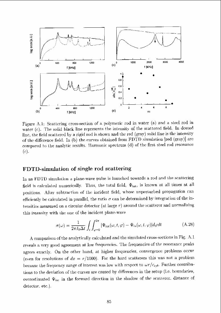
3
(A
S(A
8>
(b)
800 1200
f [kHz]
*oE
(d)
1
08
06
04
02
0
4000
Figure A 1: Scattering cross-section of a polymeric rod in water (a) and a steel rod in
water (c). The solid black line represents the intensity of the scattered held. In dotted
line, the field scattered by a rigid iod is shown and the led (gray) solid line is the intensity
of the difference field. In (b) the curves obtained from FDTD simulation [red (gray)] are
compared to the analytic results. Harmonic spectrum (d) of the first steel rod resonance
(c).
FDTD-simulation of single rod scattering
In an FDTD simulation a plane-wave pulse is launched towards a rod and the scattering
field is calculated numerically. Thus, the total field, \&tot, is known at all times at all
positions. After subtraction of the incident field, whose unperturbed propagation can
efficiently be calculated in parallel, the ratio a can be determined by integration of the in¬
tensities measured on a circular detector (at large r) around the seatterer and normalizing
this intensity with the one of the incident plane-wave
CT^) = 2^Ät//_ l*tot(w,f,v)-*in(a;,t,^)|d¥?(// (A.28)
A comparison of the analytically calculated and the simulated cross-sections in Fig. A.l
reveals a very good agreement at low frequencies. The frequencies of the resonance1 peaks
agrees exactly. On the other hand, at higher frequencies, convergence problems occur
(even for resolutions of dx — r/1000) For the hard scatterers this was not a problem
because the frequency range of interest was low with respect to ur/c^. Further contribu¬
tions to the deviation of the curves are caused by differences in the setup (i.e. boundaries,
overestimated tymc in the forward direction in the shadow of the seatterer, distance of
detector, etc.).
85
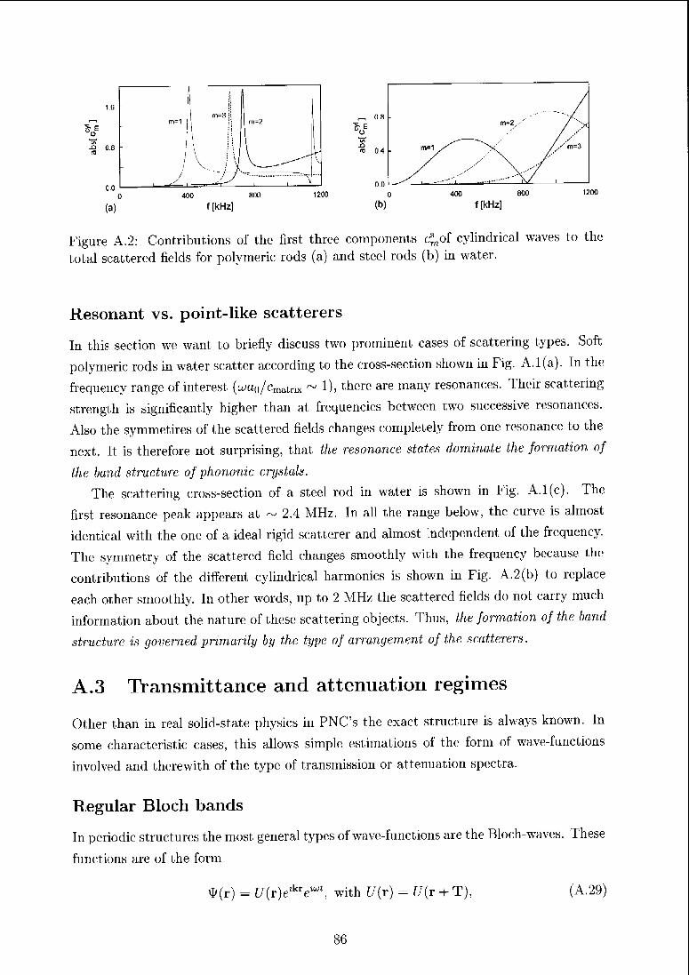
400 800
f [kHz]
1200
„08
*».Ora 04
(b)
-
m=2' / X
/ -
"
m=1.
i
y
\/
/ '* m=3
400 800
f [kHz]
Figure A.2: Contributions of the first three components <^nof cylindrical waves to the
total scattered fields for polymeric rods (a) and steel rods (b) in water.
Resonant vs. point-like scatterers
In this section we want to briefly discuss two prominent cases of scattering types. Soft
polymeric rods in water scatter according to the cross-section shown in Fig. A.1(a). In the
frequency range of interest (wa0/cmatnx ~ 1), there are many resonances. Their scattering
strength is significantly higher than at frequencies between two successive resonances.
Also the symmetires of the scattered fields changes completely from one resonance to the
next. It is therefore not surprising, that the resonance states dominate the formation of
the band structure of phononic crystals.
The scattering cross-section of a steel rod in water is shown in Fig. A.l(c). The
first resonance peak appears at ~ 2.4 MHz. In all the range below, the curve is almost
identical with the one of a ideal rigid scattcrer and almost 'ndependent of the frequency.
The symmetry of the scattered field changes smoothly with the frequency because the
contributions of the different cylindrical harmonics is shown in Fig. A.2(b) to replace
each other smoothly. In other words, up to 2 MHz the scattered fields do not carry much
information about the nature of these scattering objects. Thus, the formation of the band
structure is governed primarily by the type of arrangement of the scatterers.
A.3 Transmittance and attenuation regimes
Other than in real solid-state physics in PNC's the exact structure is always known. In
some characteristic cases, this allows simple estimations of the form of wave-functions
involved and therewith of the type of transmission or attenuation spectra.
Regular Bloch bands
In periodic structures the most general types of wave-functions are the Bloch-waves. These
functions are of the form
$(r) = C/(r)e'kV^, with U(t) = f/(r + T) (A.29)
86
where T is a primitive lattice vector of the structure. For every k the corresponding
frequency u(k) is an eigenvalue of the corresponding Hamilton operator. These; extended
Bloch waves (extended over the whole PNC) can propagate unhindered (unattenuated)
through the PNC from one end to the other. In finite PNC's, surfaces effects of course
affect the transmission spectra. The most prominent of these, the Fabry-Perot resonances,
stem from multiple surface reflections and induce a modulation with the period A/ =
ceff/2d to the low frequency range of transmittance (with the sample; thickness d). Of
course, if some of the materials employed are absorbing the Bloch-waves are damped and
transmission gently decreases towards higher frequencies.
In electronic structures, usually only solutions of the; wave equation in ranges of the
bands are considered (i.e. waves with real wave vectors). If k is allowed to be complex, on
the other hand, there is always a solution of the wave-equation (or more precisely, there
are always two,d5ü'd119) even in ranges of the bandgaps. There k — zq, with q G R3 is
purely imaginary and the corresponding waves,
#(r) = [/(r^V"', (A.30)
are obviously exponentially decaying with r and are therefore called evanescent (the wave
with exp(+kr) occurs for bandgaps opening at k = 0). Such waves are localized to the
surfaces of a PNC. In the complex k-space, the bands form continuous lines, which do
not stop abruptly at the edge of a regular Bloch band. For the evanescent waves the
imaginary wave-vectors act like attenuation parameters and the logarithmic transmission
ratio becomes directly proportional to the complex band function log(T) ~ —Im[k(uj)]
d, with d the sample thickness.'1118 In infinite PNC's, of course such waves are not of
relevance.
Diffusive wave propagation
The complete opposite of the periodically ordered PNC is the random arrangement of
scatterers. In case of strongly disordered systems and under absence of strong resonances
of the scatterers, wave propagation becomes diffusive in nature.dq9 The energy density of
the waves, $, then obeys the diffusion equation
(— + DV2)$ = 0 (A.31)
with D being the diffusion constant D. Prerequisites for the applicability of this simplified
picture is complete loss of coherence, which is easily fulfilled if scatterers are arranged
in an uncorrelated manner. Elements of the theory which are being used hen1 are very
fundamental (see for instance Gerthscn and Vogeld'4ü) and can be illustrated by the picture
of a particle P with radius r moving through a system of other particles P% with radius rx
and number density n. If these an; stationary, the mobile particle incurs a collision when
87
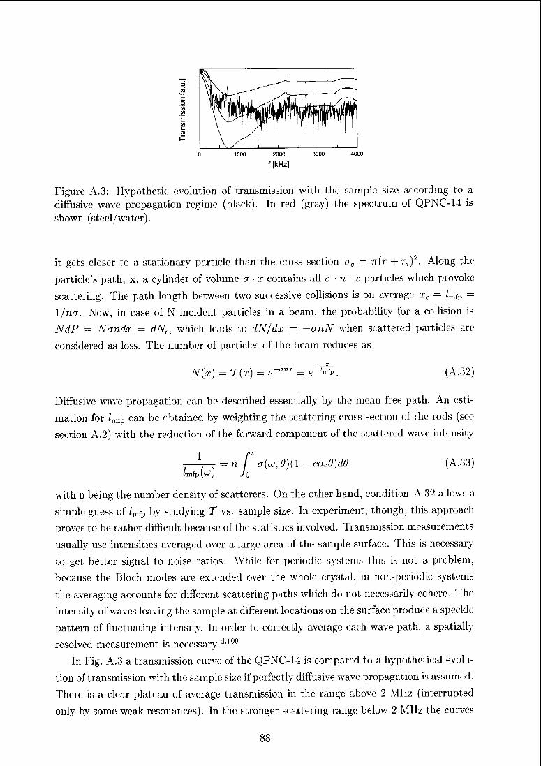
0 1000 2000 3000 4000
f [kHz]
Figure A.3: Hypothetic evolution of transmission with the sample size according to a
diffusive wave propagation regime (black). In red (gray) the spectrum of QPNC-14 is
shown (steel/water).
it gets closer to a stationary particle than the cross section ac — n(r + rt)2. Along the
particle's path, x, a cylinder of volume a • x contains all a • n x particles which provoke
scattering. The path length between two successive collisions is on average xc = lmip —
1/na. Now, in case of N incident particles in a beam, the probability for a collision is
NdP = Nandx = dNc, which leads to dN/dx — —anN when scattered particles are
considered as loss. The number of particles of the beam reduces as
N(x) = T{x) = e-'7nx^e~r^, (A.32)
Diffusive wave propagation can be described essentially by the mean free path. An esti¬
mation for /mfp can be obtained by weighting the scattering cross section of the rods (see
section A.2) with the reduction of the forward component of the scattered wave intensity
i r-—— = n / a(uj, 0)(1 - cosö)d0 (A.33)'mfp(^) ./O
with n being the number density of scattorers. On the other hand, condition A.32 allows a
simple guess of /mfp by studying T vs. sample size. In experiment, though, this approach
proves to be rather difficult because of the statistics involved. Transmission measurements
usually use intensities averaged over a large area of the sample surface. This is necessary
to get better signal to noise ratios. While for periodic systems this is not a problem,
because the Bloch modes are extended over the whole crystal, in non-periodic systems
the averaging accounts for different scattering paths which do not necessarily cohere. The
intensity of waves leaving the sample at different locations on the surface; produce a speckle;
pattern of fluctuating intensity. In order to correctly average each wave path, a spatially
resolved measurement is necessary.dl0°
In Fig. A.3 a transmission curve of the QPNC-14 is compared to a hypothetical evolu¬
tion of transmission with the sample size if perfectly diffusive wave propagation is assumed.
There is a clear plateau of average transmission in the range above 2 MHz (interrupted
only by some weak resonances). In the stronger scattering range; betaw 2 MHz the curves
88
are fai more deviating. Transmittance of waves with these frequencies clearly reflect
structural features of the quasiperiodic arrangement, which cause, for instance, the sharp
edge at — 300 kHz. This edge wc have identified as the lower edge of the first bandgap of
the PNC with the periodic average structure of the 14-fold tiling. Clearly the comparison
demonstrates the inadequacy of diffusive propagation regime for the example at hand.
Localization and renormalized diffusion
In real PNC's, neither peifect periodicity nor real randomness can ever be achieved.
There are always two competing forces at work. Order on the one hand, which drives
for extended wave1-functions and disorder on the other, which drives towaids complete
incoherence of wave propagation (i.e. diffusion). Intermediate between these two extreme
regimes, gradually increasing localization occurs. Localization is a process happening at
the edge of coherent and incoherent wave propagation but still is an interfeience effect.
Localization due to disorder has first been addressed by Anderson in 1958.d7 His
seminal input spurred a lot of work on this specific diagonally disordered Hamiltonians
(diagonal elements of the hamiltonian (on-site energies) deviate1 from an average energy by
a certain AE). Without lequirement of a specific type of structure all waves can be shown
to localize if this disorder, AE, exceeds a certain threshold value (Anderson transition).
Anderson localization is to be distinguished from localized modes due to resonances.
We want to approach localization in two steps. A first step is given by the Ioffe-
Regel criterion k • lmfp ~ l.d29 If the scattering strength of scatterers is large and their
arrangement is disordered and not too diluted (a strongly scattering medium), the mean
free path length of wave propagation becomes short, shorter than the wave length even.
If this is the case, the uncertainity of k is getting large. The spatial periodic nature
of a wave is lost thereby. Or, if Ak is getting large (spiead in reciprocal space), the
'wave' is becoming confined in direct space. The wave is not localized thereby, it is still
propagating. Only the1 coherence of its propagation is lost to a large extent.
In literature the onset of localization is usually assigned to the enhancement of coherent
backscattering/1 5> d 123 This effect is due to the interaction of two waves traveling on
exactly the same paths through the medium just in opposite directions. A significant
increase of the intensity scattered in the backwaid duection results. Thus, the overall
transmission is reduced thereby, which is termed weak localization.
With gradually stronger localization transmittance is reduced more and more until
complete isolation is achieved (i.e. conductivity, diffusion constant, etc. —> 0). Trans¬
mittance, howevei, cannot easily be guessed as in the case of classical diffusion. It is a
typical feature of systems with localized waves that properties related to conductivities
are depending on the size of the system as long as their spatial extensions are small with
respect to the localization length £. This is so, because the exponentially decaying tails
of the wave functions can still feel the boundaries and absorb or release energy from the
89
exterior. In such small systems, properties like conductivities are even depending on the
system size.dl2:i Regarding the strength of localization, two fundamental aspects must be
discussed. According to Shcngd123 fundamental difference must be made between disor¬
dered periodic systems and purely random systems. Periodic systems feature a special
type of waves, close to a band edge, whose velocity is, by means of dispersion, already
close to zero. Such waves can be expected to first localize once disorder is introduced.
With gradually stronger disorder AE, more and more waves towards the center of a band
fall for localization. At AEclü, the Anderson transition, this mobility edge reaches the
band center and all waves are localized. In real random systems there; is no such aid for
localization. Therefore AEcrit is larger.
The second most crucial parameter is the dimensionality of the system. In ID and 2D
Anderson Hamiltonians any degree of disorder AE suffices to create some localized states
(see, for instance, Economoud31). In 3D this is not the case. A first threshold value for
AE is required for the first states to localize.
For 2D random arrangements of hard scatterers, Condat and Kirkpatrkkd-22 have
calculated the localization length £(u). At 0.35 filling fraction of scatterers, they claim
a minimal length of £/a ~ 100 if a is the size of the scatterer. Since at edges of bands in
periodic or other ordered arrangements localization is much easier established, localization
could be expected also in samples of the size analyzed in this work. In 3D PNC's the
localization behavior has been theoretically studied by Sainidou and co-workers.dii8 They
found that cubic PNC's with displacive disorder are weakly and such with substitutional
disorder strongly subject to localization (periodic but 3D). In both systems a severe
enlargement of the width of bandgaps was observed.
In order to establish a connection with the description of the diffusive wave propagation
in the previous section, a short overview of the formalism of Condat and Kirkpatrickd*22' d"23
as well as Shengd123 shall be given. They state their theory in the framework of the self-
consistent diagrammatic approach (SCDA) to localization. The system under study is
a multiple scattering process in a random arrangement of scattering bodies. The phys¬
ical quantity of interest is thereby the evolution of the elastic energy density e:(r, t) =
Po[V$(r,t)]2. On a macroscopic level (for long times scales and large distances) this evo¬
lution is diffusion-like, which is in agreement with the conservation of energy (in absence
of absorption). Its propagator P is given by
P(r,£|r',0)-G2M|r',0)
and the diffusion equation Eqn. A.31
(Z)V2 + jjP(r,t\r', 0) - ö(r - r')ô(t). (A.35)
Thereby, G is the Green's function of the system from which the wave functions can be
(A.34)
90
obtained by
W(M) = y"G(r,f|r',0)/(r>/r', (A.36)
and which itself solves the wave equation Eqn. A. 18 as well as appropriate boundary
conditions [/(r') is then the excitation of the system, e.g., an incident pulse]. From the
Laplace transform of P
1 f°°
PMW) = ~J G%+(r\v')GE_(r'\r)dE, (A.37)
with/OO
G+(r|r')= / e«E±a)tG{r,t\r',Q)dt (A.38)Jo
and E± = E ± | it becomes clear, that P is a two body propagator. This may seem a
formal affair, but its physical implications are vital. The averaging of [Pfc>(r|r')]average
over a homogeneous random arrangement of scatterers is not performed on a single par¬
ticle's propagator (i.e. the temporal displacement of a particle, a random walk) but on a
property which intrinsically includes interaction of waves (an interference effect as initially
mentioned). The Fourier transform of [PB,u;(r|r')]average then becomes for k,u —> 0
[P«AE)U^ ~
_lu + D{E^)^(A-39)
P has a diffusive pole, which designates correct forms of e(r, t). Thereby, D is a frequency
dependent Diffusion constant. Diffusion is understood here in a sense, that at distances
far away over long time scales the distribution of scattered intensity would follow the laws
of diffusion, while locally full multiple scattering processes are at work.
The evaluation of the diffusion constant can now account for the typical localization
effects. The diffusion constant D is reduced by an amount, which is partially ascribed to
the coherent backscattering effect. The coherent interaction of two waves, which travel
exactly on the same path through the sample only in opposite directions results in a severe
enhancement of the backscattered intensity. The forward propagation of the average
intensity is reduced thereby - this is equivalent with a renormalization of the diffusion
constant.
91
Appendix B
Computational methods used
The methods used through out the thesis project aim to simply solve the fundamental
Eqn. A. 18 discussed in Appendix A. The approaches are very different and each of the
methods has its very own advantages. We give here only short sketches of these methods
and refer the reader to more extensive source. Descriptions and comparisons of these as
well as other methods used in the field are given, for instance by Sigalas et a/.dJ30 and
Soukoulis.d-133
B.l The plane wave expansion method
The plain wave expansion method (PWE) is transforming all variables of the wave; equa¬
tion into Fourier space. In Fourier space they are connected by systems of linear equations
which can be easily solved numerically.
The PWE-method was the first of the classical band structure calculation schemes
applied to phononic crystals.*169 In this procedure the periodic variations of the mechanical
properties p and cl are exploited to express them as Fourier scries
P(r) - p(r) = ]Tp(GmyG~rGm
c,(r) -> cl(r) = ^cf(GmyG-r. (B.l)
Due to the; periodicity of the system, the wave functions solving the wave equation must
be of Bloch type
u(r,G) = C/(r)VGr (B.2)
with U(t) — U(r + T) (Ta lattice; vector of the structure). Thereby a discretization
(required for computation) is achieved in Fourier space. Substitution of Eqns.B.l,B.2
into Eqn. A. 18 gives
p(Gm)|^(G) = y • (/i(Gm)Vu,(G)) + V • ^(GJ^pi) + £ (A(Gm)V u(G))(B.3)
92
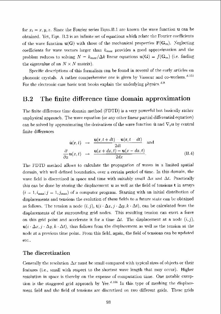
for Xi = x,y,z. Since the Fourier series Eqns.B.l are known the wave function u can be
obtained. Yet, Eqn. B.3 is an infinite set of equations which relate the Fourier coefficients
of the wave function u(G) with those of the mechanical properties F(Gm). Neglecting
coefficients for wave vectors larger than kmax provides a good approximation and the
problem reduces to solving N = kmax/Ak linear equations u(G) — /(Gm) (i.e. finding
the eigenvalue of an N x TV matrix).
Specific descriptions of this formalism can be found in several of the early articles on
phononic crystals. A rather comprehensive one is given by Vasseur and co-workers.d151
For the electronic case basic text books explain the underlying physics.'1'8
B.2 The finite difference time domain approximation
The finite difference time; domain method (FDTD) is a very powerful but basically rather
unphysical approach. The wave equation (or any other linear partial differential equation)
can be solved by approximating the derivatives of the wave function ù and Vru by central
finite differences
..
,u(r, t + dt) — u(r, t — dt)
u(r,t) ->->
—
'- and
d_ u{x + dx,t)-u(x-dx,t)dxU[ ' j
2dx[ '
The FDTD method allows to calculate the propagation of waves in a limited spatial
domain, with well defined boundaries, over a certain period of time. In this domain, the
wave field is discretized in space and time with suitably small Ax and At. Practically
this can be done by storing the displacement u as well as the field of tensions t in arrays
(?' — l,imax;i — It jmax) °f a computer program. Starting with an initial distribution of
displacements and tensions the evolution of these fields to a future state can be obtained
as follows. The tension a node (?', j), t(z • Ax, j Ay, k At), can be calculated from the
displacements of the surrounding grid nodes. This resulting tension can exert a force
on this grid point and accelerate it for a time Ai. The displacement at a node (i,j),
u(z • Ax, j • Ay, k At), thus follows from the displacement as well as the tension at the
node at a previous time point. From this field, again, the field of tensions can be updated
etc..
The discretization
Generally the resolution Ax must be small compared with typical sizes of objects or their
features (i.e., small with respect to the shortest wave length that may occur). Higher
resolution in space is thereby on the expense of computation time. One notable excep¬
tion is the staggered grid approach by Yee.d'166 In this type of meshing the displace¬
ment field and the field of tensions are discretized on two different grids. These grids
93
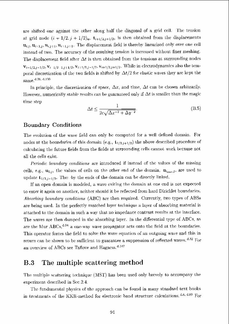
are shifted one against the other along half the diagonal of a grid cell. The tension
at grid node (i + 1/2, j + l/2)u, tî+1/2j+i/2, is then obtained from the displacements
Uj^Ui+i^Ujj+^Uj+^+x. The displacement field is thereby linearized only over one cell
instead of two. The accuracy of the resulting tension is increased without finer meshing.
The displacement field after At is then obtained from the tensions at surrounding nodes
v,_i/2j-i/2, vt_1/2+i,,+i/2, v,+1/2j-i/2, v,+i/2,j+i/2. While in electrodynamics also the tem¬
poral discretization of the two fields is shifted by At/2 for elastic waves they are kept the
same/126' di30
In principle, the discretization of space, Ax, and time, At can be chosen arbitrarily.
However, numerically stable results can be guaranteed only if At is smaller than the magic
time step
At <,
X(B.5)
~
2cVAx"2 + Ay~2
Boundary Conditions
The evolution of the wave field can only be computed for a well defined domain. For
nodes at the boundaries of this domain (e.g., ti/2,.,+1/2) the above described procedure of
calculating the future fields from the fields at surrounding cells cannot work because not
all the cells exist.
Periodic boundary conditions are introduced if instead of the values of the missing
cells, e.g., Uo,;, the values of cells on the other end of the domain, uïmaxJ, are used to
update ti/2,^+1/2- The; by the ends of the domain can be directly linked.
If an open domain is modeled, a wave exiting the domain at one end is not expected
to enter it again on another, neither should it be reflected from hard Dirichlet boundaries.
Absorbing boundary conditions (ABC) are then required. Currently, two types of ABSs
are being used. In the perfectly matched layer technique a layer of absorbing material is
attached to the domain in such a way that no impedance contrast results at the interface.
The waves are then damped in the absorbing layer. In the differential type of ABCs, as
are the Mur ABCs,d94 a one-way wave propagator acts onto the field at the boundaries.
This operator forces the field to solve the wave equation of an outgoing wave and this in
return can be shown to be sufficient to guarantee a suppression of reflected waves.d32 For
an overview of ABCs see Taflove and Hagness.d1'17
B.3 The multiple scattering method
The multiple scattering technique; (MST) has been used only brevely to accompany the
experiment described in Sec. 2.4.
The fundamental physics of the approach can be found in many standard text books
in treatments of the KKR-method for electronic band structure calculations.118'089 For
94
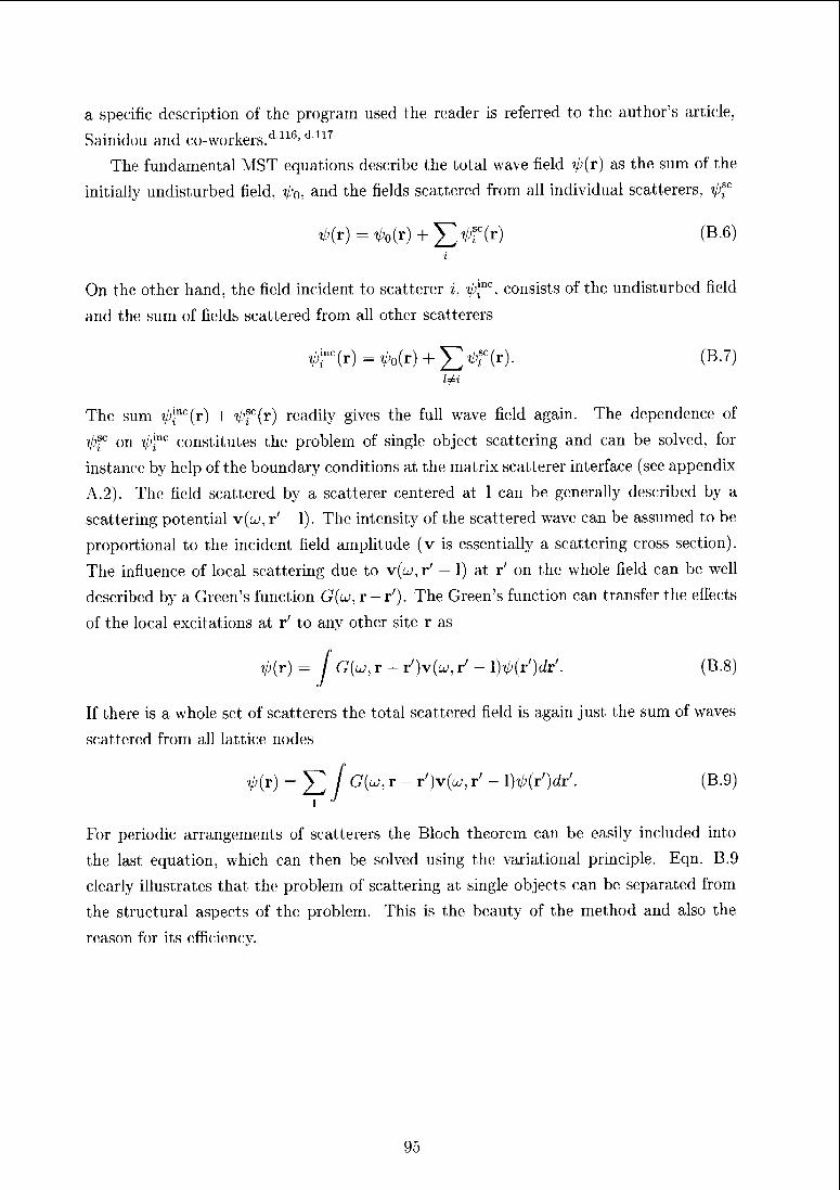
a specific description of the program used the reader is referred to the author's article,
Sainidou and co-workers.d116, d117
The fundamental MST equations describe the total wave field VKr) as the snm OI the
initially undisturbed field, t/;o, and the fields scattered from all individual scatterers, Vf°
V;(r) = ^o(r) + J>r(r) (B.6)
On the other hand, the field incident to scatterer i, ij)c, consists of the undisturbed field
and the sum of fields scattered from all other scatterers
0r(r)=V;o(r) + J>r(r)- (B-7)
The sum V;,mc(r) + V;fc(r) readily gives the full wave field again. The dependence of
0fc on V;J"r constitutes the problem of single object scattering and can be solved, for
instance by help of the boundary conditions at the matrix scatterer interface (see appendix
A.2). The field scattered by a scatterer centered at 1 can be generally described by a
scattering potential v(lj, r' — 1). The intensity of the scattered wave can be assumed to be
proportional to the incident field amplitude (v is essentially a scattering cross section).
The influence of local scattering due to v(<^, r' - 1) at r' on the whole field can be well
described by a Green's function G(u>, r — r'). The Green's function can transfer the effects
of the local excitations at r' to any other site r as
V;(r) - / G(u, r - r')v(Lj, r' - \)^(r')dr'. (B.8)
If there is a whole set of scatterers the total scattered field is again just the sum of waves
scattered from all lattice nodes
V;(r) = Y1 [ G(w' r - r')v(w' r' " WOdr'. (B.9)l
'
For periodic arrangements of scatterers the Bloch theorem can be easily included into
the last equation, which can then be solved using the variational principle. Eqn. B.9
clearly illustrates that the problem of scattering at single objects can be separated from
the structural aspects of the problem. This is the beauty of the method and also the
reason for its efficiency.
95
Appendix C
Systematic description of quasiperiodicstructures
In this appendix quasiperiodic structures and especially their higher-dimensional descrip¬
tion shall be discussed in more detail and in more illustrative ways.
A systematic description and categorization of quasiperiodic structures (quasilattices)
first has to distinguish structures, which are quasiperiodic in one-, two- or three dimensions
(and periodic 01 constant in the other ones). In the course of the cm rent thesis all
types have been treated but the focus clearly is on planar quasilattices. In 2D and 3D,
quasilattices are further specified by the degree of rotational symmetry of their diffraction
pattems. In ID structures the recursive generation (i.e. their degree of scaling symmetry)
is chaiacteristic. How and why exactly this can be achieved is described in this section
as well as in several reviews and books.d 7R< d 131' d i32' d 136' d lf>4
Crystallographic prerequisites
It is well known, that 2D (3D) translational periodic structures can exhibit 2-, 3-, 4-
and 6-fold rotational symmetries only. A 5-fold axis, or othei elements of the non-
crystallographic point groups (including rotational symmetries of any degree a e N other
than the above mentioned) are prohibited. They are prohibited because tiles (e.g., regular
pentagons) which have such a symmetry (e.g., a 5-fold axis) cannot be densely packed to
cover the plane (space) without leaving voids.
If periodicity is dropped as a restriction though, there is no need anymore foi a single
unit cell, but arrangements of different unit tiles are possible. Two kinds of rhombs, for
instance, with angles Qi — 2-7r/5 and a2 — tt/5 can be arranged to densely cover the
plane in such a way that even 10-fold global symmetry results. Quasiperiodic structures
are special cases of such airangemcnts of several constituent prototiles and have the four
properties mentioned in the1 introductory chapter on structures in Sec. 1.2
96
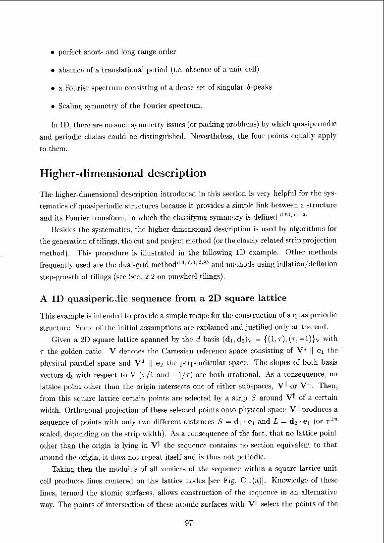
• perfect short- and long-range order
• absence of a translational period (i.e. absence; of a unit cell)
• a Fourier spectrum consisting of a dense set of singular <5-peaks
• Scaling symmetry of the Fourier spectrum.
In ID, there are no such symmetry issues (or packing problems) by which quasiperiodic
and periodic chains could be distinguished. Nevertheless, the four points equally apply
to them.
Higher-dimensional description
The higher-dimensional description introduced in this section is very helpful for the sys-
tematics of quasiperiodic structures because it provides a simple link between a structure
and its Fourier transform, in which the classifying symmetry is defined/154, d136
Besides the systematica, the higher-dimensional description is used by algorithms for
the generation of tilings, the cut and project method (or the closely related strip projection
method). This procedure is illustrated in the following ID example. Other methods
frequently used are the dual-grid method'14' d-3, d95 and methods using inflation/deflation
step-growth of tilings (see Sec. 2.2 on pinwheel tilings).
A ID quasiperiodic sequence from a 2D square lattice
This example is intended to provide a simple recipe for the construction of a quasiperiodic
structure. Some of the initial assumptions are explained and justified only at the end.
Given a 2D square lattice spanned by the d basis (di,d2)v = {(1,T), (T, _i)}v with
t the golden ratio. V denotes the Cartesian reference space consisting of V" || ei the
physical parallel space and V1 || e2 the perpendicular space. The slopes of both basis
vectors d; with respect to V (r/1 and — 1/r) are both irrational. As a consequence, no
lattice point other than the origin intersects one of either subspaces, V" or V1. Then,
from this square lattice certain points are selected by a strip S around V" of a certain
width. Orthogonal projection of these selected points onto physical space V" produces a
sequence of points with only two different distances S — di ei and L — d2 • ei (or r±n
scaled, depending on the strip width). As a consequence of the fact, that no lattice point
other than the origin is lying in VH the sequence contains no section equivalent to that
around the origin, it does not repeat itself and is thus not periodic.
Taking then the modulus of all vertices of the sequence within a square lattice unit
cell produces lines centered on the lattice nodes [see Fig. C.l(a)]. Knowledge of these
lines, termed the atomic surfaces, allows construction of the sequence in an alternative
way. The points of intersection of these atomic surfaces with V" select the points of the
97
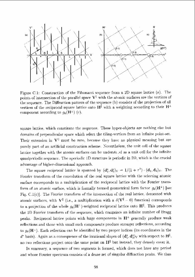
Figure Cl: Construction of the; Fibonacci sequence from a 2D square lattice (a). The
points of intersection of the parallel space V'l with the atomic surfaces are the vertices of
the sequence. The Diffraction pattern of the sequence (b) consists of the projection of all
vertices of the reciprocal square lattice onto H" with a weighting according to their Hx
component according to ^(H-1) (c).
square lattice, which constitute the sequence. These hyper-objects are nothing else but
domains of perpendicular space which select the tiling-vertices from an infinite point-set.
Their extension in V" must be zero, because they have no physical meaning but are
purely part of an artificial construction scheme. Nevertheless, the unit cell of the square
lattice together with the atomic surfaces can be understc jd as a unit cell for the infinite
quasiperiodic sequence. The aperiodic ID structure is periodic in 2D, which is the crucial
advantage of higher-dimensional approach.
The square reciprocal lattice is spanned by (d^d^v = 1/(1 + r2) (di,d2)v- The
Fourier transform of the convolution of the real square lattice with the selecting atomic
surface corresponds to a multiplication of the reciprocal lattice with the Fourier trans¬
form of an atomic surface, which is formally termed geometrical form factor gfc(Hx) [see
Fig. C.l(c)]. The Fourier transform of the intersection of the real lattice, decorated with
atomic surfaces, with V^ (i.e., a multiplication with a £(V" - 0) function) corresponds
to a projection of the whole pfc(Hx)-weighted reciprocal lattice onto H'1. This produces
the ID Fourier transform of the sequence, which comprises an infinite number of Bragg
peaks. Reciprocal lattice points with large components in H-1 generally produce weak
reflections and those with small such components produce stronger reflections, according
to ^(H-1). Each reflection can be identified by two proper indices (its coordinates in the
d* basis). Again as a consequence of the irrational slopes of (d^d^v with respect to H",
no two reflections project onto the same point on H" but instead, they densely cover it.
In summary, a sequence of two segments is formed, which does not have any period
and whose Fourier spectrum consists of a dense set of singular diffraction peaks. We thus
98
deduce, the structure must be quasiperiodic. And indeed the chosen example sequence is
the well known Fibonacci chain (for certain widths of S).
The remaining questions concerning the description of our Fibonacci example are, how
can we know in advance; which lattice and what widths of the selection strip must be taken.
First, the basis vectors of the square lattice are the eigenvectors of the recursive growth
matrix of the Fibonacci sequence (i.e. eigenvectors of its scaling symmetry operator)
(S, L) -, (S, L) f J 1\=(L,L + S)=t-(S,L),
with L and S the long and short elements of the sequence. Or the other way round, the
sequence; is lying in a subspace of a 2D Cartesian lattice. This whole subspace is invariant
under scaling with factor r, and so is the sequence itself. The width of the strip is not
clear in advance. Yet, variation of the width of the strip reveals, that the same sequences
appear again and again at certain values. These different (singular) values for the strip
width producing exactly a Fibonacci chain are reflecting again its self-similarity. The
atomic surfaces can either be determined subsequently, when the singular values for the
strip width are known or it can be deduce from the; closeness condition. This condition
guarantees that from every unit cell of the square lattice; only (maximally) one point is
selected for the sequence [see the dashed horizontal line connecting two atomic surfaces
in the first unit cell of the square lattice in Fig. C.l(a)]. Their length is then equivalent
with the projection of a unit cell of the square lattice onto V-1.
A 2D quasiperiodic structures from higher dimensional lattices
In order to obtain a structure, which is quasiperiodic in two (three) dimensions, the rank
n of the; Z-module of its embedding space must certainly be large;r than two (thre;e). Its
specific dimension is given by the desired symmetry of the structure. The construction
of a tiling of, for instance, 10-fold symmetry can certainly be; achie'ved by using a 10D
cubic lattice. In a first step the cigenspaces of a 10-fold axis (i.e., subspaces, which remain
invariant under cyclic permutation of the basis vectors di,..., d10) are determined. The
2D tiling must lie in such an eigenspace; in order to have a 10-fold symmetry. This
eigenspace is then assigned V" while all other dimensions constitute V1, which is of
n — 2 — 8 dimensions. A transformation of coe)rdinate,s with V^1 brings everything
into the form analogous to that in the Fibonacci example in the previous subsection
(a Cartesian reference lattice and a skewly embedded e;ubie- d basis). A quasiperiodic
structure can be obtained by projection of vertices of the Z10-module selected by a strip
S\\ V" ontoVH.
A structure featuring 10-fold diffraction symmetry, however, can be obtained also from
five or even four dimensions (because of the centrosymmetry of all diffraction patterns).
This is a consequence of the fact that the projection e)f the; 5-fold reciproe-al lattice onto
99
V" produces also a 10-fold symmetric pattern. This is analogous to the example of a 3D
cubic lattice projected along the [1 1 1] direction onto a (1 1 1) plane. The projection
along [1 1 1] transforms the 3 axis into a 6-fold axis. This effect N —> 2N applies to all
odd N. Further reductions of the required rank of the Z-module can be achieved by using
non-cubic d basis, which better fit the desired symmetry (for instance, the dodecagonal
structure can be produced from 12, 6 and 4 dimensions). The minimal dimension required
is given by Euler's totient function <f>(n) (i.e., the number of integers smaller or equal to
n with no common devisor greater than ldn).
The atomic surfaces in higher dimensions have a dimension smaller than or equal to
the dimension of V1- and may adopt very complex shapes or also consist of several uncon¬
nected pieces. The closeness condition equally applies and becomes rather complicated
with the complicated shapes of the atomic surfaces.
Quasiperiodic structures can be conveniently and systematically described by higher-
dimensional periodic unit cells, given by a basis and the exact shape of the atomic surfaces
therein. Additionally a direct link to the Fourier transform of the structure is established.
Periodic average structures
In the introduction to this section we already stated that there is a certain degree of peri¬
odicity associated with every quasiperiodic structure. This degree varies for the different
types of structures and can be used to characterize them (see article 5 in Sec. 2.3). The
periodic average strucjire (PAS) of a quasiperiodic tiling is defined as a periodic structure
whose reciprocal lattice basis vectors point to the strongest reflections in the diffraction
image of the tiling.018' dl3T The concept of the PAS has been already successfully applied
to surface science of quasicrystals.dl38> dlfi1Deposition of crystalline matter on quasicrys-
tal surfaces was found to evolve in such a way that coincidence of the crystal lattice with
the PAS is best achieved.
In the higher-dimensional description, the PAS of a 2D tiling can be understood as
follows: choosing two strong reflections, i.e. two reciprocal lattice vectors from the infinite
Z-module, corresponds to a cut of a plane through the nD reciprocal embedding space.
The plane spanned by the origin and the two reflections contains a subset of reflections.
For large n it is easier to imagine the cutting as stepwise reduction of dimensions. A nD
polytope is cut by a (n — 1)D hyperplane to give a (n — 1)D polytope. This polytope
is cut by a (n - 2)D hyperplane to give a (n - 2)D polytope etc.. Since the 2D plane
used in the last step must cut an infinite plane out of the original reciprocal lattice,
all previous cuts must cut parallel to this plane (include this plane). To give a simple
example, suppose we want to choose one reflection additional to the origin from a 3D
reciprocal lattice. We can then first cut space with any arbitrary plane including the
two reflections and then cut the line out of this plane. In direct space; this is equivalent
100
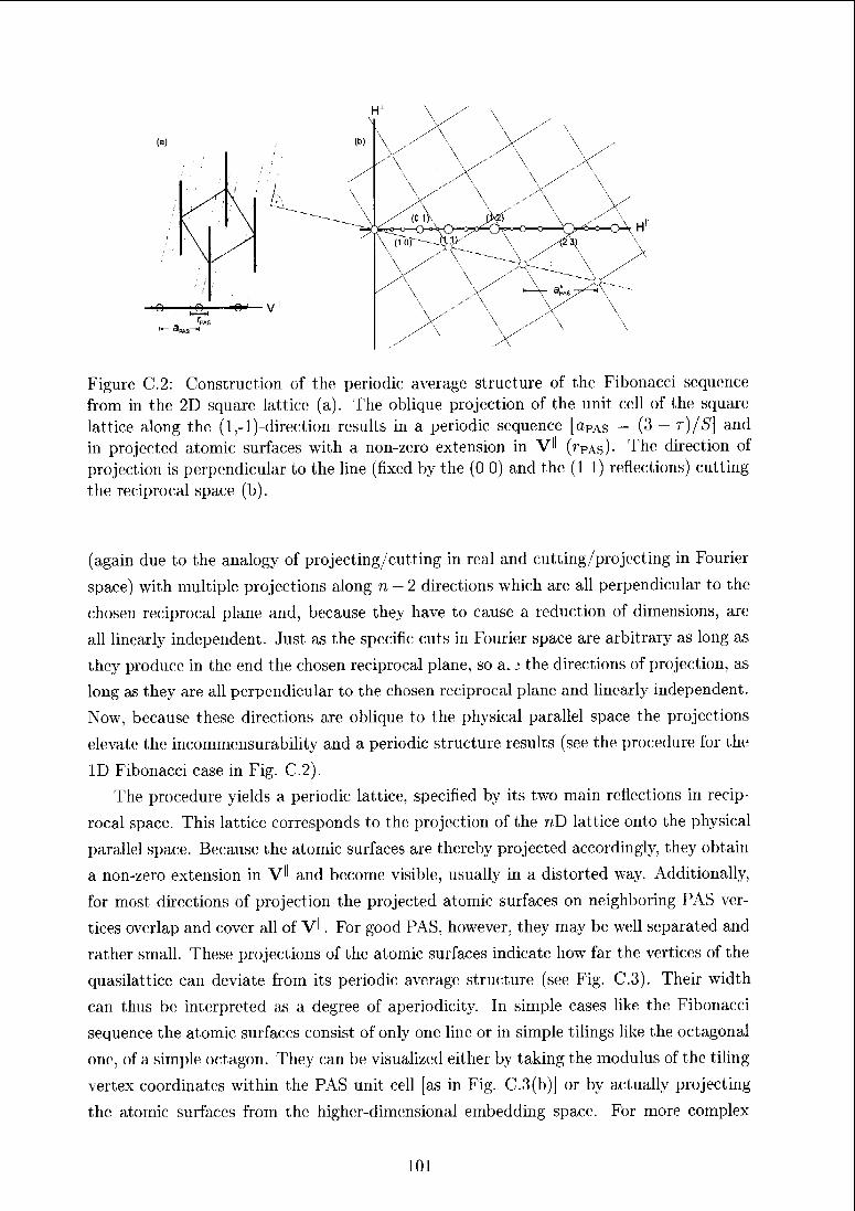
Figure C.2: Construction of the periodic average structure of the Fibonacci sequence
from in the 2D square lattice (a). The oblique projection of the unit cell of the square;
lattice along the (l,-l)-direction results in a periodic sequence [aPAs — (3 — t)/S\ and
in projected atomic surfaces with a non-zero extension in V" (rPAs)- The direction of
projection is perpendicular to the line (fixed by the (0 0) and the (1 1) reflections) cutting
the reciprocal space (b).
(again due to the analogy of projecting/cutting in real and cutting/projecting in Fourier
space) with multiple projections along n — 2 directions which are all perpendicular to the
chosen reciprocal plane and, because they have to cause a reduction of dimensions, are
all linearly independent. Just as the specific cuts in Fourier space are arbitrary as long as
they produce in the end the chosen reciprocal plane, so a.j the directions of projection, as
long as they are all perpendicular to the chosen reciprocal plane and linearly independent.
Now, because these directions are oblique to the physical parallel space the projections
elevate the incommensurability and a periodic structure results (see the procedure for the
ID Fibonacci case in Fig. C.2).
The procedure yields a periodic lattice, specified by its two main reflections in recip¬
rocal space. This lattice corresponds to the projection of the nD lattice onto the physical
parallel space. Because the atomic surfaces are thereby projected accordingly, they obtain
a non-zero extension in V" and become visible, usually in a distorted way. Additionally,
for most directions of projection the projected atomic surfaces on neighboring PAS ver¬
tices overlap and cover all of VK For good PAS, however, they may be well separated and
rather small. These projections of the atomic surfaces indicate how far the vertices of the
quasilattice can deviate from its periodic average; structure (see Fig. C.3). Their width
can thus be interpreted as a degree of aperiodicity. In simple cases like the Fibonacci
sequence the atomic surfaces consist of only one line or in simple tilings like the octagonal
oik;, of a simple octagon. They can be visualized either by taking the modulus of the tiling
vertex coordinates within the PAS unit cell [as in Fig. C.3(b)J or by actually projecting
the atomic surfaces from the higher-dimensional embedding space. For more complex
101
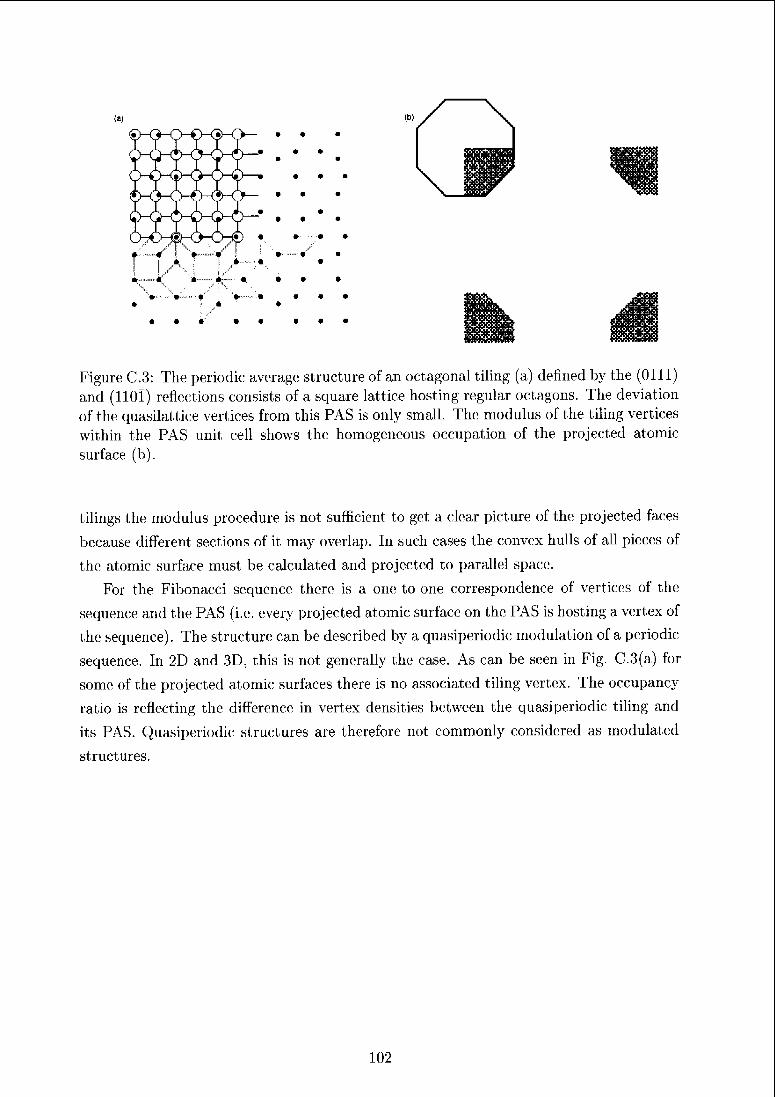
Figure C.3: The periodic average structure of an octagonal tiling (a) defined by the (Olli)and (110Ï) reflections consists of a square lattice hosting regular octagons. The deviation
of the quasilattice vertices from this PAS is only small. Tin; modulus of the tiling vertices
within the PAS unit cell shows the homogeneous occupation of the projected atomic
surface (b).
tilings the modulus procedure is not sufficient to get a clear picture of the projected faces
because different sections of it may overlap. In such cases the convex hulls of all pieces of
the atomic surface must be calculated and projected to parallel space.
For the Fibonacci sequence there is a one-to-one correspondence of vertices of the
sequence and the PAS (i.e. (-very projected atomic surface on the PAS is hosting a vertex of
the sequence). The structure; can be described by a quasiperiodic modulation of a periodic
sequence. In 2D and 3D, this is not generally the case. As can be seen in Fig. C.3(a) for
some of the projected atomic surfaces there is no associated tiling vertex. The occupancy
ratio is reflecting the difference in vertex densities between the quasiperiodic tiling and
its PAS. Quasiperiodic structures are therefore not commonly considered as modulated
structures.
102
Bibliography
[d.l] http://phys.lsu.edu/ jdowling/pbgbib.html1
fd.2| http://www.phys.uoa.gr/pliononicR/
[d.3] http://mcs.open.ac.uk/ugg2/quasi.shtml
[d.4] J.L. Aragon, G.G. Naumis, and M. Torres, Acta Cryst. A58, 352 (2002).
[d.5] E. Akkermans, P.E. Wolf, R. Maynard, and G. Maret, J. Phys. France 49, 77
(1988).
[d.6l E.L. Albuquerque and M.G. Cottam, Phys. Rep. 376, 225 (2003).
[d.7] P.M. Anderson, Phys. Rev. 109, 1492 (1958).
[d.8] N.W. Ashcroft and N.D. Mermin, Solid State Physics, Thomson Learning, London
(1976).
[d.9] F. Axel and D. Gratias, Beyond Quasicrystals, Springer Verlag, Berlin (1995).
Id.10] H. Aynaou, E.H. El Boudouti, Y.El Hassouani, A.Akjouj, B. Djafari-Rouhani,
J. Vasseur, A. Benomar, and V.R. Velasco, Phys. Rev. E 72, 056601 (2005).
[d.ll] M. Baake in: J.B. Suck, M. Schreiber, and P. Haussier (Ed.), Quasicrystals: In¬
troduction to Structure, Physical Properties, and Applications, 17, Springer Berlin
(2002).
[d.l2j M. Baake, D. Frettlöh, and U. Grimm, Phil. Mag. 87 (in press, 2007).
[d.13] R. Berenson and J.L. Birman, Phys. Rev. B 34, 8926 (1986).
fd.14] M. Bcrtolotti, P. Masculli, and C. Sibilia, Optics Letters 19, 777 (1994).
[d.15] R.T. Bratfalean, A.C. Peacock, N.G.R. Broderick, K. Gallo, and R. Lewen,
Opt. Lett. 30, 424 (2005).
1 Titles of the bibliography appear in alphabetical order of the first author's name.
103
[d.16] S. David, A. Chelnokov, and J.M. Lourtioz, IEEE J. Quant. Electr. 37, 1427
(2001).
d.17] N.G. De Brujn, J. Phys. (Paris) 47, 9 (1986).
d.18] A. Cervellino and W. Steurer, Acta. Cryst. A 58, 180 (2002).
d.19] Y.S. Chan, CT. Chan, and Z.Y. Liu, Phys. Rev. Lett. 80, 956 (1998).
d.20] S.S.M. Cheng, L.M. Li, CT. Chan, and Z.Q. Zhang, Phys. Rev. B 59, 4091
(1999).
d.21] A.N. Cleland, D.R. Schmidt, and CS. Yung, Phys. Rev. B 64, 172301 (2001).
d.22] C.A. Condat and T.R. Kirkpatrick, Phys. Rev. Lett. 58, 226 (1987).
d.23] C.A. Condat and T.R. Kirkpatrick in: P. Sheng (Ed.), Scattering and localization of
classical waves in random media (World Scientific scries on directions in condensed
matter physics ; vol. 8), World Scientific, cop., Singapore (1990).
d.24] L. Dal Negro, M. Stolfi, Y. Yi, J. Michel, X. Duan, L.C Kimerling, J. LeBlanc,
and J. Haavisto, Appl. Phys. Lett. 84, 5186 (2004).
d.25] A. Delia Villa, S. Enoch, G. Taycb, V. Pierro, V. Galdi, and F. Capolino,
Phys. Rev. Lett. 94, 183903 (2005).
d.26] B. Djafari-Rouhani, Y. Pennec, and J.O. Vasseur, private communication (2004).
d.27] R.D. Doolittle and H. Ueberall, J. Acoust. Soc. Am. 39, 272 (1966).
d.28] R.D. Doolittle and H. Ueberall, J. Acoust. Soc. Am. 43, 1 (1967).
d.29] J.M. Drake and A.Z. Genack, Phys. Rev. Lett. 63, 259 (1989).
d.30] M. Duneau and M. Audier, Acta Cryst. A55, 746 (1999).
d.31] E.N. Economou, Green's functions in quantum physics, Springer Verlag, Berlin
(1979).
d.32] B. Engquist and A. Majada, Math. Comp. 31, 629 (1977).
d.33] M.J. Escuti and G.P. Crawford, Opt. Eng. 43, 1973 (2004).
d.34] J.J. Faran, J. Acoust. Soc. Am. 23, 405 (1951).
d.35] Z. Feng, X. Zhang, Y.Q. Wang, Z.Y. Li, B. Cheng, and D.Z. Zhang,
Phys. Rev. Lett. 94, 247402 (2005).
104
[d.36] R.P. Feynman, R.B. Leighton, and M. Sands, The Feynman Lectures on Physics
Vol. II, Addison-Wesley Publishing Company, Reading Massachusetts (1964).
fd.37] F. Gähler and J. Rhyner, J. Phys. A: Math. Gen. 19, 267 (1986).
[d.38] R.C. Gauthier and K. Mnaymneh, Opt. Comm. 13, 1986 (2005).
|d.39] W. Gellermann, M. Kohomoto, B. Sutherland, and P. C. Taylor,
Phys. Rev. Lett. 72, 633 (1994).
[d.401 C. Gerthsen and H. Vogel, Physik. 17te Auflage, Springer, Berlin (1993).
fd.41] C. Godrèche and J.M. Luck, J. Phys. A: Math. Gen. 23, 3769 (1990).
[d.42] C. Goffaux, J. Saiichoz-Dchcsa, A.L. Yeyati, Ph. Lambin, A. Khelif, J.O. Vasseur,
and B. Djafari-Rhouhani, Phys. Rev. Lett. 88, 225502 (2002).
[d.43] S.P. Gorkhali, J. Qi, and G.P. Crawford, J. Opt. Soc. Am. B 23, 149 (2006).
[d.44] P. Gummelt, Geometr. Dedic. 62, 1 (1986).
[d.45l B.C. Gupta and Z. Ye, Phys. Rev. E 67, 036603 (2003).
[d.46l J. Hartwig, S. Agliozzo, J. Baruchel, R. Colella, M. deBoissieu, J. Gastaldi,
H. Klein, L. Mancini, and J. Wang, J Physics D 34, A103 (2001).
[d.47j M. Hase, H. Miyazaki, M. Egashira, N. Shinya, K.M. Kojima, and S.I. Uchida,
Phys. Rev. B 66, 214205 (2002).
[d.48] T. Hattori, N. Tsurumachi, S. Kawato, and H. Nakatsuka, Phys. Rev. B 50, 4220
(1994).
[d.49] S. He and J.D. Maynard, Phys. Rev. Lett. 62, 1888 (1989).
[d.50] V. Heine, Surf. Sei. 2, 1 (1964).
[d.51] M. Hoffe and M. Baake, Z. Kristallogr. 215, 441 (2000).
[d.52] N. Horiuehi, Y. Segawa, T. Nozokido, K. Mizuno, and H. Miyazaki, Opt. Lett. 29,
1084 (2004).
[d.53] R.M. Hornreich, M. Kugler, S. Shtrikman, and C. Sommers, J. Phys. 1 France 7,
509 (1997).
[d.54] C. Janot, Quasicrystals : a primer - Second ed., Clarendon Press, Oxford (1997).
fd.55] T. Janssen, Acta Crystallogr. A 42, 261 (1986).
105
[d.56] X.Y. Jiang, Y.G. Zhang, S.L. Feng, K.C. Huang, Y.H. Yi, and J.D. Joannopoulos,
Appl. Phys. Lett. 86, 1110 (2005).
[d.57] C.J. Jin, B.Y. Cheng, B.Y. Man, Z.L. Li, and D.Z. Zhang, Phys. Rev. B 61,
107C2 (2000).
[d.58] C.J. Jin, B.Y. Cheng, B.Y. Man, Z.L. Li, and D.Z. Zhang, Appl. Phys. Lett. 75,
1848 (1999).
[d.59] E. Jurdik et ed., Phys. Rev. B 69, 201102(R) (2004).
[d.60] M. Kafesaki and E.N. Economou, Phys. Rev. B 52, 13317 (1995).
[d.61] M.A. Kaliteevski, S. Brand, R.A. Abram, T.F. Krauss, R. DeLa Rue, and P. Mil¬
lar, Nanotechnology 11, 274 (2000).
[d.62] M.A. Kaliteevski, V.V. Nikolaev, R.A. Abram, and S. Brand, Opt. Speetr. 91,
109 (2001).
[d.63] M.A. Kaliteevski, D.M. Boggs, S. Brand, R.A. Abram, and V.V. Nikolaev,
Phys. Rev. E 73, 05G616 (2006).
fd.64] S. Kanoko, K. Edagawa, R. Tamura, and Y. G. So, Phil. Mag., submitted (2007).
[d.65] A. Khelif, B. Djafari-Rhouhani, J.O. Vasseur, P.A. Deymier, Ph. Lambin, and
L. Dobrzyns*i, Phys. Rev. B 65, 174308-1 (2002).
[d.66] A.D. Klironomos and E.N. Economou, Solid State Commun. 105, 327 (1997).
[d.67] M. Kohmoto and B. Sutherland, Phys. Rev. B 34, 3849 (1986).
fd.68l M. Kohmoto, B. Sutherland, and K. Iguchi, Phys. Rev. Lett. 58, 2436 (1987).
[d.69] M.S. Kushwaha, P. Halevi, L. Dobrzynski, and B. Djafari-Rouhani,
Phys. Rev. Lett. 71, 2022 (1993).
[d.70] M.S. Kushwaha, Appl. Phys. Lett. 70, 3218 (1997).
[d.71] M.S. Kushwaha and B. Djafari-Rouhani, J. of Sound and Vibration 218, 697
(1998).
[d.72] Y. Lai, X. Zhang, and Z.Q. Zhang, J. Appl. Phys. 91, 6191 (2002).
fd.73] Y. Lai, Z.Q. Zhang, C.H. Chan, and L. Tsang, Phys. Rev. B 74, 054305 (2006).
d.74] A. Lakhtakia, V.V. Varadan, and V.K. Varadan, J. Acoust. Soc. Am. 83, 1267
(1988).
106
fd.75] L.D. Landau and E.M. Lifshitz, Theory of elasticity - Third English edition,
Butterworth-Heinemann, Oxford (2002).
fd.76] A.V. Laviinenko, S.V. Zhukovsky, K.S. Sandomirski, and S.V. Gaponenko,
Phys. Rev. B 65, 036621 (2002).
fd.77] A. Ledeimann, L. Cademartiii, M. Hermatschweiler, C. Toninelli, G.A Ozin,
D.S. Wiersma, M. Wegener, and G. von Freymann, Nature Materials (London)
5, 942 (2006).
[d.78] D. Levine and P.J. Steinhardt, Phys. Rev. B 34, 596 (1986).
[d.79] M. Li, Y. Liu, and Z.Q. Zhang, Phys. Rev. B 61, 16193 (2000).
[d.80] Z. Liu, C.T. Chan, P. Sheng, A.L. Goertzen, and J.H. Page, Phys. Rev. B 62,
2446 (2000).
[d.81J Z. Liu, X. Zhang, Y. Mao, Y.Y. Zhu, Z. Yang, C.T. Chan, and P. Sheng, Science
289, 1734 (2000).
fd.82] J-M. Lourtioz, H. Benistiy, V. Berger, J-M. Gerard, D. Maystre, and A. Tchel-
nokov, Photonic Crystals Towards Nanoscale Photonic Devices. Springer Berlin
(2005).
[d.83] J.M. Luck, C. Godrèche, A. Janner, and T. Janssen, J. Phys. A 26, 1951 (1993).
[d.84] D. Lusk and R. Placido, Thin Solid Films 492, 226 (2005).
[d.85] B.Q. Ma, T. Wang, Y. Sheng, P.G. Ni, Y.Q. Wang, B.Y. Cheng, and D.Z. Zhang,
Appl. Phys. Lett. 87, 51103 (2005).
[d.86] W. Man, M. Megens, P.J Steinhardt, and P.M. Chaikin, Nature 436, 993 (2005).
[d.87] R. Meilin, K. Bajema, R. Claike, F.Y. Juang, and P.K. Bhattacharya,
Phys. Rev. Lett. 55, 1768 (1985).
[d.88] G. Mie, Ann. Phys. (Leipzig) 25, 377 (1908).
d.89] U. Mizntani, Introduction to the electron theory of metals, Cambridge University
Press, Cambridge (2001).
d.90] J.A. Monsoriu, C.J. Zapata-Rodrigue/, E. Silvestre, and W.D. Furlan,
Opt. Comm. 252, 46 (2005).
d.91] A. Montalbän, V.R. Vela&co, J. Tutor, and F.J. Fernandez-Vehcia, Phys. Rev. B
70, 132301 (2004).
107
[d.92] L. Moretti, I. Rea, L. Rotiroti, I. Rendina, G. Abbate, A. Marino, and L. Do
Stefano, Opt. Expr. 14, 6264 (2006).
[d.93] Laser Direct-Write Processing, MRS Bulletin 32, No. 1 (2007).
[d.94j G. Mur, IEEE Trans. Electromagn. Compat., 23, 377 (1987).
fd.95] G.G. Naumis and J.L. Aragon, Z. Kristallogr. 218, 397 (2003).
fd.96l M. Notomi, H. Suzuki, T. Tamamura, and K. Edagawa, Phys. Rev. Lett. 92,
123906 (2004).
fd.97] K. Nozaki, A. Nakagawa, D. Sano, and T. Baba, IEEE J. Selected Topics in
Quantum Eletronics 9, 1355 (2003).
[d.98] S. Ostlund and R. Pandit, Phys. Rev. B 29, 1394 (1984).
[d.99] J.H. Page, H.P. Schriemer, A.E. Bailey, and D.A. Weitz, Phys. Rev. E 52, 3106
(1995).
[d.100] J.H. Page, H.P. Schriemer, I.P. Jones, P. Sheng, and D.A. Weitz, Pysica A 241,
64 (1997).
[d.1011 J.H. Page, A.L. Goertzen, S. Yang, Z. Liu, C.T. Chan, and P. Sheng, NATO ASI
on Photonic Crystals and Light Localization, Crete (2000).
|d,102] G.J. Parker, M.D.B. Charlton, M.E. Zoorob, J.J. Baumberg, M.C. Netti, and
T. Lee, Phil. Trans. R. Soc. A 364, 189 (2006)
[d.103] R.W. Peng, X.Q. Huang, E. Qiu, M. Wang, A. Hu, S.S. Jiang, and M. Mazzer,
Appl. Phys. Lett. 80, 3063 (2002).
[d.l04j R.E. Prange, D.R. Grempel, and S. Fishman, Phys. Rev. B 28, 7370 (1983).
|d,105l I.E. Psarobas, N. Stefanou, and A. Modinos, Phys. Rev. B 62 (1), 278 (2000).
[d.1061 I.E. Psarobas, A. Modinos, R. Sainidou, and N. Stefanou, Phys. Rev. B 65 (1),
064307 (2001).
[d.1071 C. Radin, Annal. Math. 139, 661 (1994).
[d.108] P. Repetowicz and J. Wolny, J. Phys. A: Math. Gen. 31, 6873 (1998).
[d.109] P. Repetowicz, U. Grimm, and M. Schreiber, Phys. Revl. B 58, 13482 (1998).
[d.110] R. Riklund and M. Sevcrin, J. Phys. C 21, 3217 (1988).
[d.llll C. Rockstuhl, U. Peschel, and F. Lederer, Opt. Lett. 31, 1741 (2006).
108
[d.112] Y. Roichman and D.G. Grier, Opt. Expr. 13, 5434 (2005).
fd.113] J. Romero-Vivas, D.N. Chigrin, A.V. Lavrinenko, and C.M. Sotomayor-Torres,
Phys. Status Solidi (a) 202, 997 (2005).
[d.114] D.R. Roper, D.M. Beggs, M.A. Kaliteevski, S. Brand, and R.A. Abram, Journal
of Modern Optics 53, 407 (2006).
[d.115] R. Sainidou and N. Stefanou, Phys. Rev. B 66, 212301 (2002).
[d.H6j R. Sainidou and N. Stefanou, Phys. Rev. B 69, 064301 (2004).
[d. 117] R. Sainidou, N. Stefanou, I.E. Psarobas, and A. Modinos, Computer Physics
Communications 166, 197 (2005).
[d.118] R. Sainidou, N. Stefanou, and A. Modinos, Phys. Rev. Lett. 94, 205503 (2005).
[d.H9j R. Sainidou, N. Stefanou, I.E. Psarobas, and A. Modinos, Z. Kristallogr. 220,
848 (2005).
[d.120] .I.V. Sanchez, D. Caballero, R. Mârtinez-Sala, J. Sânchez-Dehesa, F. Meseguer,
J. Llinares, and F. Gâlvez, Phys. Rev. Lett. 80 (24), 5325 (1998).
[d.121] L. Sanchis, A. Hakansson, F. Cervera, and J. Sanchéz-Dehesa, Phys. Rev. B 67,
035422 (2003).
fd.1221 D. Shechtman, I. Blech, D. Gratias, and J.W. Cahn, Phys. Rev. Lett, 53, 1951
(1984).
[d.l23j P. Sheng, Introduction to Wave Scattering, Localization and Mesoscopic Phenomena,
Academic Press, San Diego (1995).
fd.124] P. Sheng, X.X. Zhang, Z. Liu, and C.T. Chan, Physica B 338, 201 (2003).
fd.125] P. Sheng and C.T. Chan, Z. Kristallogr. 220, 871 (2005).
[d.126] M. Shen and W. Cao, Appl. Phys. Lett. 75 (23), 3713 (1999).
[d,127j C. Sibilia, LS. Nefedov, M. Scalora, and M. Bertolotti, J. Opt. Soc. Am. B 15,
1947 (1998).
[d.128] M.M. Sigalas and E.N. Economou, J. Appl. Phys. 75 (6), 2845 (1994).
Id.l29j M.M. Sigalas, J. Appl. Phys. 84 (6), 3026 (1998).
[d.130] M. Sigalas, M.S. Kushwaha, E.N. Economou, M. Kafesaki, I.E. Psarobas, and
W. Steurer, Z. Kristallogr. 220, 765 (2005).
109
d.131] J.E.S. Socolar and P.J. Steinhardt, Phys. Rev. B 34, 617 (1986).
d.132] J.E.S. Socolar, Phys. Rev. B 39, 10519 (1989).
d.133] CM. Soukoulis, Photonic Band Gap Materials, Kluwer Academic Publishers, Dor¬
drecht (1996).
d.135] N. Stetiger, J-L. Rehspringer, and C. Hirlimann, J. Lumin. 21, 278 (2006).
d.136] W. Steurer and T. Haibach in: Z. M. Stadnik (Ed.), Physical properties of qua-
sicrystals, Springer, Berlin, Heidelberg (1999).
d.137] W. Steurer and T. Haibach, Acta. Cryst. A 55, 48 (1999).
d.138] W. Steurer, Mat. Sei. Eng. A 294, 268 (2000).
d.139] W. Steurer, Z. Kristallogr. 219, 391 (2004).
d.l40j W. Steurer, Z Kristallogr. 221, 402 (2006).
d.141] D. Sutter, G. Krauss, and W. Steurer, MRS Proceedings 805, 99 (2004).
d.1421 D. Sutter and W. Steurer, Phys. Status Solidi C 1, 2716 (2004).
d.1431 D. Sutter-Widmer, S. Deloudi, and W. Steurer, Phil. Mag. 87, 3095 (2007).
d.144] D. Sutter-Widmer and W. Steurer, Phys. Rev. B 75, 134303 (2007).
d.145] D. Sutter-Widmer, S. Deloudi and W. Steurer, Phys. R,ev. B 75, 094304 (2007).
d.146] A.P. Sutton, Electronic structure of materials, Oxford university press, Oxford
(1993).
d.147] A. Taflove and S.C. Hagness, Computational electrodynamics : the finite-difference
time-domain method - 2nd ed., Artech House, Boston (2000).
d.148] W.Y. Tarn, Appl. Phys. Lett. 89, 251111 (2006).
d.l49j S. Tamura and J.P. Wolfe, Phys. Rev. B 36, 3491 (1987).
d.150] H. Tsunetsugu, T. Fujiwara, K. Ueda, and T. Tokihiro, Phys. Rev. B 43, 8879
(1991).
d.151] J.O. Vasseur, B. Djafari-Rouhani, L. Dobrzynski, M.S. Kushwaha, and P. Halevi,
J. Phys. Condens. Matter 6, 8759 (1994).
d.152] J.O. Vasseur, P.A. Deymier, M. Chenni, M. Djafari-Rouhani, L. Dobrzynski, and
D. Prévost, Phys. Rev. Lett. 86, 3014 (2001).
110
[d.153] J.O. Vasseur, P.A. Dcymier, A. Khelif, Ph. Lambin, B. Djafari-Rouhaiii,
A. Akjouj, L. Dobrzynski, N. Fettouhi, and J. Zemmouri, Phys. Rev. E 65, 56608
(2002).
d.1541 M.S. Vasconcelos and E.L. Albuquerque, Phys. Rev. B 59, 11128 (1999).
d.l55j V.R. Velasco, R. Perez-Alvarez, and F. Garcia-Moliner, J. Phys.: Condens. Mat¬
ter 14, 5933 (2002).
d.l56j K. Wang, S. David, A. Chelnokov, and J.M. Louritioz, Journal of Modern Optics
50, 2095 (2003).
d.157] K. Wang, Phys. Rev. B 73, 235122 (2006).
d.158] X. Wang, C.Y. Ng, W.Y. Tarn, CT. Chan, and P. Sheng, Adv. Mater. 15, 1526
(2003).
d.159] Y. Wang, X. Hu, X. Xu, B. Cheng, and D. Zhang, Phys. Rev. B 68, 165106
(2003).
d.l60j Y. Wang, J. Liu, B. Zhang, S. Feng, and Z.Y. Li, Phys. Rev. B 73, 155107 (2006).
d.1611 Y. Weisskopf, S. Burkardt, M. Erbudak, and J.N. Longchamps, Surf. Sei. 601,
544 (2007).
d.162] F. Wu, Z. Liu, and Y. Liu, Phys. Rev. E 66, 046628 (2002).
d.163] E. Yablonovitch, Phys. Rev. Lett. 58, 2059 (1987).
d.164] A. Yamamoto, Acta Cryst. A 52, 509 (1996).
d.1651 Y. Yang, S.H. Zhang, and G.P. Wang, Appl. Phys. Lett. 88, 51104 (2004).
d.1661 K.S. Yee, IEEE Trans. Antennas Propagat. 14, 302 (1966).
d.167] J. Zarbakhsh, F. Hagmann, S.F. Mingaleev, K. Busch, and K. Hingerl,
Appl. Phys. Lett. 84, 4687 (2004).
d.168] X. Zhang, Z.Q. Zhang, and CT. Chan, Phys. Rev. B 63, 081105(R) (2001).
d.l69j Z.S. Zhang, B. Zhang, J. Xu, K. Xu, Z.J. Yang, Z.X. Qin, T.J. Yu, and D.P. Yu,
Appl. Phys. Lett. 88, 171103 (2006).
d.170] X. Zhang, Phys. Rev. B 75, 024209 (2007).
d.1711 S.N. Zhu, Y.Y Zhu, Y.Q. Qin, H.F. Wing, C.Z. Ge, and N.B. Ming,
Phys. Rev. Lett. 78, 2752 (1997).
11]
[d.172] M.E. Zoorob, M.D.B. Charlton, G.J. Parker, J.J. Baumberg, and M.C. Netti,
Nature 404, 740 (2000).
Acknowledgements
I am deeply indebted to Prof. W. Steurer for his support of this thesis, his constant
participation, his many ideas and suggestions as well as his patience. I much enjoyed the
freedom he granted me in my work.
Many members of the laboratory of crystallography earn my gratitude. They provided
first of all a friendly ambience at the laboratory but also constant support with whatever
problems there were.
We thank Dr. J.O. Vasseur and his collaborators at Université de Lille for their introduc¬
tory advises and provision of FDTD codes. We also thank him for acting as co-referee of
this thesis.
We thank Dr. U.G. Grimm for surveying this thesis.
We thank Dr. Y. Psarobas at University of Athens for fruitful discussions and collaboration
in the sphere project.
We thank Dr. R. Sainidou at University of Athens for discussions.
I thank the students which have contributed with semester works or thesis: Edith Fuchs-
berger, Stefan Waldburger, Angela Furier. Pedro Neves and Patrick Itten.
My parents have provided unconditional support during all of my education. They have
much earned my deepest gratitude (not only for this, of course).
My thanks to my loving wife Barbara.
Curriculum Vitae
Name
First name
Date of birth
Place of birth
Citizen
Marital status
Current adress
Sutter - Widmer
Daniel
May 12 1978
Lausen (BL)
of Bretzwil (BL)
married to Barbara Sutter - Widmer
Triemlistrasse 186, CH-8047 Zürich
2003 - 2007
2002
1998 - 2003
1994 - 1997
1985 - 1994
Ph. D. studies, Lab. of Crystallography, ETH Zürich
Material science studies, Australian National University (Canberra
ACT)
Material science studies, ETH Zürich
Gymnasium in Liestal (BL)
Elementary school in Holstein and Progymnasium in Oberdorf (BL)
2003 - 2007
2003
2002 - 2003
Ph. D. thesis "phononic quasicrystals" at the laboratory of crys¬
tallography ETHZ under supervision of Prof. W. Steurer.
Diploma thesis "Phononische Kristalle" at the laboratory of crys¬
tallography ETHZ under supervision of Prof. W. Steurer.
Semester thesis "Kristallstruktur von magnetoplastischen
NiMnGa-Legicrungen" at the institute of applied physics ETHZ
under supervision of Prof. G. Kostorz.
Publications
D. Sutter, G. Krauss, and W. Steurer, MRS Proceedings 805, 99 (2004).
D. Sutter and W. Steurer, Phys. Status Solidi C 1, 2716 (2004).
D. Sutter-Widmer, S. Deloudi, and W. Steurer, Phil. Mag. 87, 3095 (2007).
D. Sutter-Widmer and W. Steurer, Phys. Rev. B 75, 134303 (2007).
D. Sut ter-Widmer, S. Dcloudi and W. Steurer, Phys. Rev. B 75, 094304 (2007).
W. Steurer and D. Sutter-Widmer, Sol. State Phen. 130, 33 (2007).
W. Steurer and D. Suttor-Widmor, J. Phys. D: Appl. Phys. 40, R229 (2007).