Embed Size (px)
Citation preview

October 2011 •1/6
Phonak CROS
A guide to verifying CROS and Bi-CROS fittings using probe-microphone measures
Introduction
A common management approach for those with hearing loss
in one ear that isn’t directly aidable but normal/near-normal
hearing in the other ear is to fit a system that transfers sound
from the unaidable side across to the better side. Known as
Contralateral Routing of the Signal, or CROS (Harford & Barry,
1965), this approach generally entails a microphone worn on/in
the unaidable ear which sends its output via either a wire or
wireless transmission to an amplifier and receiver worn
behind/in the normal/near-normal hearing ear. A so called
transcranial CROS can also be achieved by transferring
information from the unaidable to good ear via bone
conduction using either a high powered in-the-ear hearing aid
(Hayes & Chen, 1998) or a bone anchored hearing aid (Hol et al.,
2010). Because the hearing in the better ear is normal/near-
normal, little or no amplification is provided to the crossed
signal as the concept is simply to overcome the head-shadow
effect (Courtois et al.,1988).
For patients who also have a hearing loss in their better hearing
ear, a Bi-CROS (Bilateral Contralateral Routing of the Signal)
solution will be more suitable (Dillon, 2001). In a Bi-CROS
system, a microphone is worn behind both ears. Again, the
signal from the unaidable ear is transferred from one side of
the head to the other; however, this signal is then amplified
according to the hearing loss in the better ear. At the same
time, the microphone behind the better albeit impaired ear is
also amplified according to the hearing loss on this side.
Interestingly, Mueller & Hawkins (1992) reported that patients
sometimes find it challenging to reliably report whether their
CROS system/transmitter is operational, particularly if the
better ear is normal/near-normal. Thus, probe microphone
measures present an ideal, objective way for verifying if
CROS/Bi-CROS systems are functioning and overcoming the
head shadow effect (Pumford, 2005). Further support for
utilizing probe-microphone measures comes from MarkeTrak
findings, showing those patients receiving best fitting practice
experience double the reduction in hearing handicap compared
to those that don’t (Kochkin, 2011).
This document is based on the verification protocol outlined by
Pumford (2005) and uses case examples, photos of the test set-
up and typical electro-acoustic results to clearly illustrate how
to verify CROS/Bi-CROS fittings using both the real-ear
insertion-gain (REIG) and Speech-Map (SpMap) method.
Equipment Set-Up & Requirements
To enable accurate probe microphone measures of
CROS/Bi-CROS system function, real-ear measurement systems
(such as the Audioscan Verifit system) must have two reference
microphones, one placed on each ear, and the ability to
switch between these whilst keeping the same probe-
microphone active. This enables the hearing healthcare
professional to switch the active reference microphone across
ears, which is essential for accurately comparing output when
sound is presented to the better versus unaidable ear. Regarding equip-ment set-up, the probe-microphone is only
inserted into the normal/better hearing ear. This is because the better hearing ear is the only ear that has an output from
the CROS/Bi-CROS system.
CROS Fittings
To illustrate the method for verifying CROS fittings, consider
this case of a 24 year old male who suffered a sudden severe-
profound sensorineural hearing loss on the right, with very poor
residual speech discrimination in this ear. The left ear has
normal hearing (Fig. 1). He attends university and is having
difficulty hearing in tutorials, especially people on his right side.
This difficulty also occurs socially, when he is a passenger in the
car (left hand drive road system) and in his part-time job. He is
keen for help with his hearing and his hearing healthcare
professional fitted a Phonak Cassia microM and Phonak CROS
BTE transmitter for trial.
October 2011 •2/6
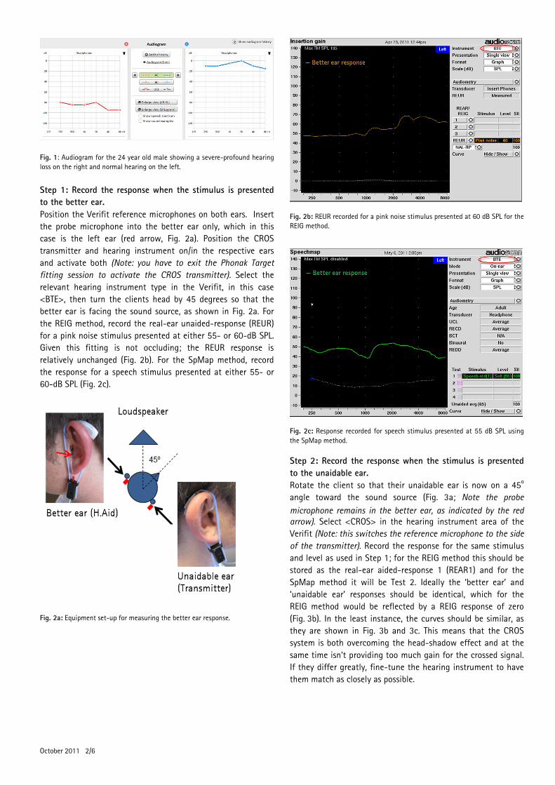
Fig. 1: Audiogram for the 24 year old male showing a severe-profound hearing
loss on the right and normal hearing on the left.
Step 1: Record the response when the stimulus is presented
to the better ear.
Position the Verifit reference microphones on both ears. Insert
the probe microphone into the better ear only, which in this
case is the left ear (red arrow, Fig. 2a). Position the CROS
transmitter and hearing instrument on/in the respective ears
and activate both (Note: you have to exit the Phonak Target
fitting session to activate the CROS transmitter). Select the
relevant hearing instrument type in the Verifit, in this case
<BTE>, then turn the clients head by 45 degrees so that the
better ear is facing the sound source, as shown in Fig. 2a. For
the REIG method, record the real-ear unaided-response (REUR)
for a pink noise stimulus presented at either 55- or 60-dB SPL.
Given this fitting is not occluding; the REUR response is
relatively unchanged (Fig. 2b). For the SpMap method, record
the response for a speech stimulus presented at either 55- or
60-dB SPL (Fig. 2c).
Fig. 2a: Equipment set-up for measuring the better ear response.
Fig. 2b: REUR recorded for a pink noise stimulus presented at 60 dB SPL for the
REIG method.
Fig. 2c: Response recorded for speech stimulus presented at 55 dB SPL using
the SpMap method.
Step 2: Record the response when the stimulus is presented
to the unaidable ear.
Rotate the client so that their unaidable ear is now on a 45o
angle toward the sound source (Fig. 3a; Note the probe
microphone remains in the better ear, as indicated by the red arrow). Select <CROS> in the hearing instrument area of the
Verifit (Note: this switches the reference microphone to the side
of the transmitter). Record the response for the same stimulus
and level as used in Step 1; for the REIG method this should be
stored as the real-ear aided-response 1 (REAR1) and for the
SpMap method it will be Test 2. Ideally the ‘better ear’ and
‘unaidable ear’ responses should be identical, which for the
REIG method would be reflected by a REIG response of zero
(Fig. 3b). In the least instance, the curves should be similar, as
they are shown in Fig. 3b and 3c. This means that the CROS
system is both overcoming the head-shadow effect and at the
same time isn’t providing too much gain for the crossed signal.
If they differ greatly, fine-tune the hearing instrument to have
them match as closely as possible.

October 2011 •3/6
Fig. 3a: Equipment set-up for measuring the unaidable ear response.
Fig. 3b: REAR1 recorded for a pink noise stimulus presented at 60 dB SPL for
the REIG method.
Fig. 3c: Response recorded for speech stimulus presented at 55 dB SPL using
the SpMap method.
Step 3: Record a response with the stimulus presented at 00
azimuth.
This ensures that the REAR response is smooth and there are no
irregularities in the response. This can be done with either
reference microphone selected (i.e., <CROS> or <BTE> selected
in the Verifit hearing instrument menu) because they are
equidistant from the sound source.
Bi-CROS Fittings
To illustrate the method used for Bi-CROS fittings, consider the
case of a 48 year old male who had longstanding mild-
moderate hearing loss bilaterally which he tolerated.
Unfortunately, he sustained a head injury during a car accident
that fractured his right temporal bone causing a profound
hearing loss on this side (Fig. 4). His previously annoying but
tolerable hearing issues have now become a huge burden and
are impacting on the quality of his life. Therefore a Phonak
Solana microM and Phonak CROS BTE are fitted for trial.
Fig. 4: Audiogram for the 48 year old male showing a profound hearing loss on
the right – following the head injury and a mild-moderate hearing loss on the
left .
Step 1: Fit and verify the hearing instrument in the
conventional way.
Position the Verifit reference microphones on both ears and
insert the probe microphone into the better ear only (red arrow,
Fig. 5a).
Fig. 5a: Test set-up for conventional verification of the left hearing instrument.

October 2011 •4/6
Fig. 5b: Example of electro-acoustic results using the REIG method.
Fig. 5c: Example of electro-acoustic results using the SpMap method.
Position both the hearing instrument and CROS transmitter
on/in the ears and select <on ear measure> & the relevant
hearing device in the Verifit, in this case <BTE>. Activate the
hearing instrument only and verify your hearing instrument in
the normal fashion using either the REIG or SpMap method
(Fig. 5b and 5c respectively).
Step 2: Record the response from the better ear.
Turn the CROS transmitter on (Note: you need to exit Phonak
Target fitting session to activate the CROS transmitter). Keep the
hearing instrument type the same in the Verifit, in this case
<BTE>. Turn clients head by 45 degrees so that the better ear is
angled toward the sound source (Fig. 6a). For the REIG method,
present a pink noise stimulus at either 55- or 60-dB SPL and
record this response as the REUR (Fig. 6b). For the SpMap
method, present a speech stimulus at either 55- or 60-dB SPL
and record this as Test 1 (Fig. 6c).
Fig. 6a: Equipment set-up for measuring the better ear response.
Fig. 6b: REUR recorded for a pink noise stimulus presented at 55 dB SPL for the
REIG method.
Fig. 6c: Response recorded for speech stimulus presented at 55 dB SPL using
the SpMap method.

October 2011 •5/6
Step 3: Record the response from the unaidable ear. Rotate the client so that their unaidable ear is now on a 45
o
angle toward the sound source (Fig. 7a; Note - the probe
microphone remains in the better ear, as indicated by the red arrow). Select <CROS> in the hearing instrument area of the
Verifit (Note: this switches the reference microphone to the side
of the transmitter). Record the response for the same stimulus
type and level as used in Step 2. For the REIG method, record
this as the REAR1, and for the SpMap method it will be Test 2.
Again, the better ear and unaidable ear responses should be
identical, or in the least instance quite similar, as they are in
this case (Fig. 7b and 7c). For the REIG method, close similarity
between the better and unaidable ear responses is reflected by
a REIG curve of approximately zero. When the responses have
good similarity, this means that the Bi-CROS system is both
overcoming the head shadow effect and the crossed signal is
receiving appropriate gain for the hearing loss in the better ear.
If they differ greatly, fine-tune the instrument using the
microphone balancing tool in Phonak Target in order to have
them match as closely as possible.
Step 4: Record a response with the stimulus presented at 00
azimuth with the Bi-CROS system active. This is to ensure the response is smooth and there are no irregularities. This can be done with either reference micro-phone selected (i.e., <CROS> or <BTE> selected in the Verifit hearing instrument menu) because they are equidistant from the sound source.
Fig. 7a: Equipment set-up for measuring the unaidable ear response.
Fig. 7b: REUR recorded for a pink noise stimulus presented at 55 dB SPL for the
REIG method.
Fig. 7c: Response recorded for speech stimulus presented at 55 dB SPL using
the SpMap method.
Summary
Probe microphone measures provide an easy, objective and
reliable way to verify CROS and Bi-CROS fittings. You can use
either the REIG or SpMap method depending on which you are
most familiar with. The main system requirements are two
probe and reference microphone complexes and the ability to
switch reference microphones whilst keeping one probe
microphone active to record output in the better hearing ear.

October 2011 •6/6 © Phonak AG All rights reserved
References
Courtois et al. (1988). Hearing aid fitting in asymmetrical
hearing loss. In J.H. Jensen (Ed) Hearing aid fitting: theoretical
and practical views (243-256.) Copenhagen: Stougard Jensen
Dillon, H. 2001. Hearing aids. Sydney: Boomerang / New York:
Thieme
Harford, E. and Barry, F. 1965 A rehabilitative approach to the
problem of unilateral hearing impairment: Contralateral routing
of signals. J. Speech & Hearing Disorders, Vol. 30: pp. 121-138
Hayes, D. E. and Chen, J. M. (1998) Bone-conduction
amplification with completely-in-the-canal hearing aids. J. Am
Acad. Audiol., Vol. 9(1): pp. 59-66.
Hol.et al. 2010. Pilot study of the effectiveness of the
conventional CROS, the transcranial CROS and the BAHA
transcranial CROS in adults with unilateral inner ear deafness.
Eur Arch Otorhinolaryngol., Vol. 267(6): pp. 889-898. Epub
2009 Nov 11
Kochkin, S. 2011. MarkeTrak VIII: Patients report improved
quality of life with hearing aid usage. Hearing Journal, Vol.
64(6): pp. 25-32.
Mueller, H.G. and Hawkins, D. B. 1992. Assessment of fitting
arrangements, special circuitry, and features. In Mueller HG,
Hawkins DB, Northern JL, eds., Probe Microphone
Measurements: Hearing Aid Selection and Assessment. San
Diego: Singular, pp: 201-225.
Pumford, J. October 2005. Benefits of probe-mic measures with
CROS/Bi-CROS fittings. The Hearing Journal, Vol. 58(10): pp.
34-40.
This article was written by David Crowhen, Audiologist, Phonak
NZ Ltd