Embed Size (px)
Citation preview

MAN-0044 Rev 15 IR3S-XX December 02, 2008
PHOENIX Triple Infrared Flame Detector
User Manual
Models:
IR3S-A, IR3S-R, IR3S-D, IR3S-AD


Net Safety Monitoring Inc.
MAN-0044 Rev 15 IR3S-XX 3 December 02, 2008
IMPORTANT INFORMATION
This manual is for informational purposes only. Although every effort has been made to ensure the correctness of the information, technical inaccuracies may occur and periodic changes may be made without notice. Net Safety Monitoring Inc., assumes no responsibility for any errors contained within this manual.
If the products or procedures are used for purposes other than as described in the manual, without receiving prior confirmation of validity or suitability, Net Safety Monitoring Inc., does not guarantee the results and assumes no obligation or liability.
No part of this manual may be copied, disseminated or distributed without the express written consent of Net Safety Monitoring Inc.
Net Safety Monitoring Inc., products are carefully designed and manufactured from high quality components and can be expected to provide many years of trouble free service. Each product is thoroughly tested, inspected and calibrated prior to shipment. Failures can occur which are beyond the control of the manufacturer. Failures can be minimized by adhering to the operating and maintenance instructions herein. Where the absolute greatest of reliability is required, redundancy should be designed into the system.
Warranty
Net Safety Monitoring Inc., offers a pro-rated 7 year warranty on the IR3S, from date of purchase.
No other warranties or liability, expressed or implied, will be honoured by Net Safety Monitoring Inc.
Contact Net Safety Monitoring Inc., or an authorized representative for details.
We welcome your input at Net Safety Monitoring. If you have any comments please contact us at the phone/address below or visit our web site and complete our on-line customer survey: www.net-safety.com.
Contact Information
Net Safety Monitoring Inc. 2721 Hopewell Place NE Calgary, AB Canada T1Y 7J7 Telephone: (403) 219-0688 Fax: (403) 219-0694 www.net-safety.com E-mail: [email protected]
Copyright © 2007 Net Safety Monitoring Inc. Printed in Canada
Net Safety Monitoring Inc
TABLE OF CONTENTS IMPORTANT INFORMATION ............................................................................. 3
WARRANTY ............................................................................................................. 3 CONTACT INFORMATION ......................................................................................... 3
INTRODUCTION .................................................................................................... 5
LOCATE DETECTOR ............................................................................................ 5
POTENTIAL FIRE SOURCES ....................................................................................... 5 POTENTIAL INHIBITORS ........................................................................................... 5 IMMUNE ................................................................................................................... 5 SENSITIVITY ............................................................................................................ 6 FIELD OF VIEW (AS PER FM AND NFPA DEFINITION) .............................................. 6 SENSITIVITY SETTING CONSIDERATIONS ................................................................. 6 NOTE: THE DATA IN TABLE ABOVE IS NOT FM PERFORMANCE VERIFIED. ................ 6 INSTALLATION CONSIDERATIONS ............................................................................ 6
UNPACK ................................................................................................................... 7
FIELD INSTALLATION ......................................................................................... 8
WIRING .................................................................................................................... 8 GROUNDING ............................................................................................................ 9 SEALING .................................................................................................................. 9 CONNECTING ........................................................................................................... 9 NON-ISOLATED AND ISOLATED POWER CONFIGURATION (IR3S-A OR IR3S-AD ONLY) ...................................................................................................................... 9
DETECTOR SETUP .............................................................................................. 13
SYSTEM SENSITIVITY ............................................................................................. 13 Important Fire Sensitivity Considerations ........................................................ 13 Time Delay Settings of 3, 5 and 10 seconds ...................................................... 13 Sensitivity Setting .............................................................................................. 13 DIP Switch Access ............................................................................................ 13
RELAY SETTINGS (IR3S-R ONLY) .......................................................................... 14 Coil Status Setting ............................................................................................. 14 Relay Contact Setting ........................................................................................ 14
MODBUS RTU ( IR3S-D & AD) ............................................................................ 15 Install Phoenix PC Set Up Software ................................................................. 15 Modbus Set Up .................................................................................................. 16
Get Current Setting ........................................................................................... 17 Modbus Set Up Failure/Reset ........................................................................... 17
DETECTOR FUNCTIONALITY ......................................................................... 17
START UP PROCEDURE ........................................................................................... 17 MONITOR ............................................................................................................... 18 CONDITION STATUS—CURRENT OUTPUT .............................................................. 18 CONDITION STATUS—LEDS ................................................................................. 18 AUTOMATIC DIGITAL ZOOM (ADZ) ...................................................................... 19
TESTING ................................................................................................................. 20
AUTOMATIC VISUAL INTEGRITY (VI) TEST ........................................................... 20
MAINTAIN ............................................................................................................. 20
CLEAN THE WINDOW/LENS ................................................................................... 20 O-RING .................................................................................................................. 20
TROUBLE SHOOT ................................................................................................ 21
HOW TO RETURN EQUIPMENT ...................................................................... 22
APPENDIX A: ELECTROSTATIC SENSITIVE DEVICE (ESD) .............. 23
APPENDIX B: RESISTANCE TABLE (OHMS) ........................................... 24
APPENDIX C: SPECIFICATION ................................................................... 25
APPENDIX D: IR3S DATA .............................................................................. 26
Net Safety Monitoring Inc.
MAN-0044 Rev 15 IR3S-XX 5 December 02, 2008
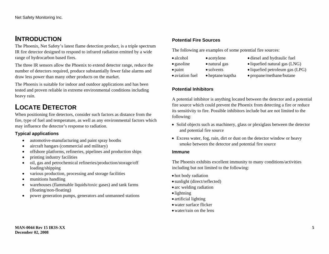
INTRODUCTION The Phoenix, Net Safety’s latest flame detection product, is a triple spectrum IR fire detector designed to respond to infrared radiation emitted by a wide range of hydrocarbon based fires. The three IR sensors allow the Phoenix to extend detector range, reduce the number of detectors required, produce substantially fewer false alarms and draw less power than many other products on the market. The Phoenix is suitable for indoor and outdoor applications and has been tested and proven reliable in extreme environmental conditions including heavy rain.
LOCATE DETECTOR When positioning fire detectors, consider such factors as distance from the fire, type of fuel and temperature, as well as any environmental factors which may influence the detector’s response to radiation.
Typical applications • automotive-manufacturing and paint spray booths • aircraft hangars (commercial and military) • offshore platforms, refineries, pipelines and production ships • printing industry facilities • oil, gas and petrochemical refineries/production/storage/off
loading/shipping • various production, processing and storage facilities • munitions handling • warehouses (flammable liquids/toxic gases) and tank farms
(floating/non-floating) • power generation pumps, generators and unmanned stations
Potential Fire Sources
The following are examples of some potential fire sources:
• alcohol • acetylene • diesel and hydraulic fuel • gasoline • natural gas • liquefied natural gas (LNG) • paint • solvents • liquefied petroleum gas (LPG) • aviation fuel • heptane/naptha • propane/methane/butane
Potential Inhibitors
A potential inhibitor is anything located between the detector and a potential fire source which could prevent the Phoenix from detecting a fire or reduce its sensitivity to fire. Possible inhibitors include but are not limited to the following:
• Solid objects such as machinery, glass or plexiglass between the detector and potential fire source
• Excess water, fog, rain, dirt or dust on the detector window or heavy smoke between the detector and potential fire source
Immune
The Phoenix exhibits excellent immunity to many conditions/activities including but not limited to the following:
• hot body radiation • sunlight (direct/reflected) • arc welding radiation • lightning • artificial lighting • water surface flicker • water/rain on the lens
Net Safety Monitoring Inc
MAN-0044 Rev 15 IR3S-XX 6 December 02, 2008
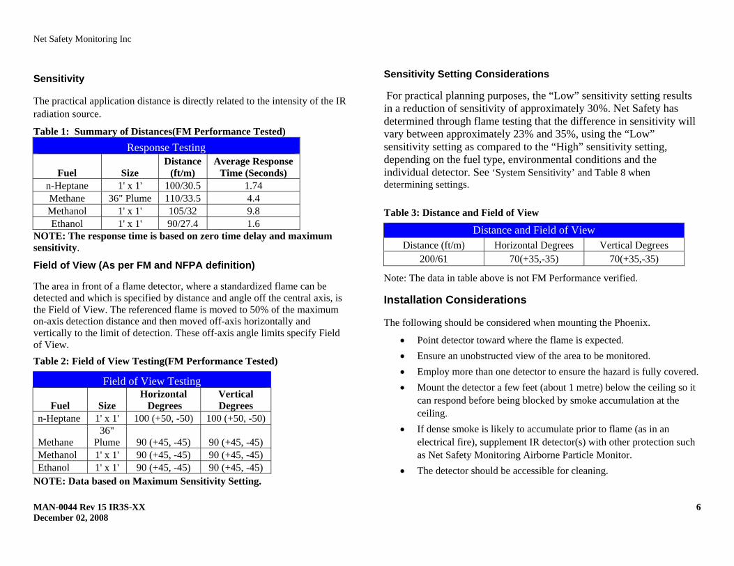
Sensitivity
The practical application distance is directly related to the intensity of the IR radiation source.
Table 1: Summary of Distances(FM Performance Tested) Response Testing
Fuel Size Distance
(ft/m) Average Response
Time (Seconds) n-Heptane 1' x 1' 100/30.5 1.74 Methane 36" Plume 110/33.5 4.4 Methanol 1' x 1' 105/32 9.8 Ethanol 1' x 1' 90/27.4 1.6
NOTE: The response time is based on zero time delay and maximum sensitivity.
Field of View (As per FM and NFPA definition)
The area in front of a flame detector, where a standardized flame can be detected and which is specified by distance and angle off the central axis, is the Field of View. The referenced flame is moved to 50% of the maximum on-axis detection distance and then moved off-axis horizontally and vertically to the limit of detection. These off-axis angle limits specify Field of View. Table 2: Field of View Testing(FM Performance Tested)
Field of View Testing
Fuel Size Horizontal Degrees
Vertical Degrees
n-Heptane 1' x 1' 100 (+50, -50) 100 (+50, -50)
Methane 36"
Plume 90 (+45, -45) 90 (+45, -45) Methanol 1' x 1' 90 (+45, -45) 90 (+45, -45) Ethanol 1' x 1' 90 (+45, -45) 90 (+45, -45)
NOTE: Data based on Maximum Sensitivity Setting.
Sensitivity Setting Considerations
For practical planning purposes, the “Low” sensitivity setting results in a reduction of sensitivity of approximately 30%. Net Safety has determined through flame testing that the difference in sensitivity will vary between approximately 23% and 35%, using the “Low” sensitivity setting as compared to the “High” sensitivity setting, depending on the fuel type, environmental conditions and the individual detector. See ‘System Sensitivity’ and Table 8 when determining settings. Table 3: Distance and Field of View
Distance and Field of View Distance (ft/m) Horizontal Degrees Vertical Degrees
200/61 70(+35,-35) 70(+35,-35)
Note: The data in table above is not FM Performance verified.
Installation Considerations
The following should be considered when mounting the Phoenix.
• Point detector toward where the flame is expected. • Ensure an unobstructed view of the area to be monitored. • Employ more than one detector to ensure the hazard is fully covered. • Mount the detector a few feet (about 1 metre) below the ceiling so it
can respond before being blocked by smoke accumulation at the ceiling.
• If dense smoke is likely to accumulate prior to flame (as in an electrical fire), supplement IR detector(s) with other protection such as Net Safety Monitoring Airborne Particle Monitor.
• The detector should be accessible for cleaning.
Net Safety Monitoring Inc
MAN-0044 Rev 15 IR3S-XX 7 December 02, 2008
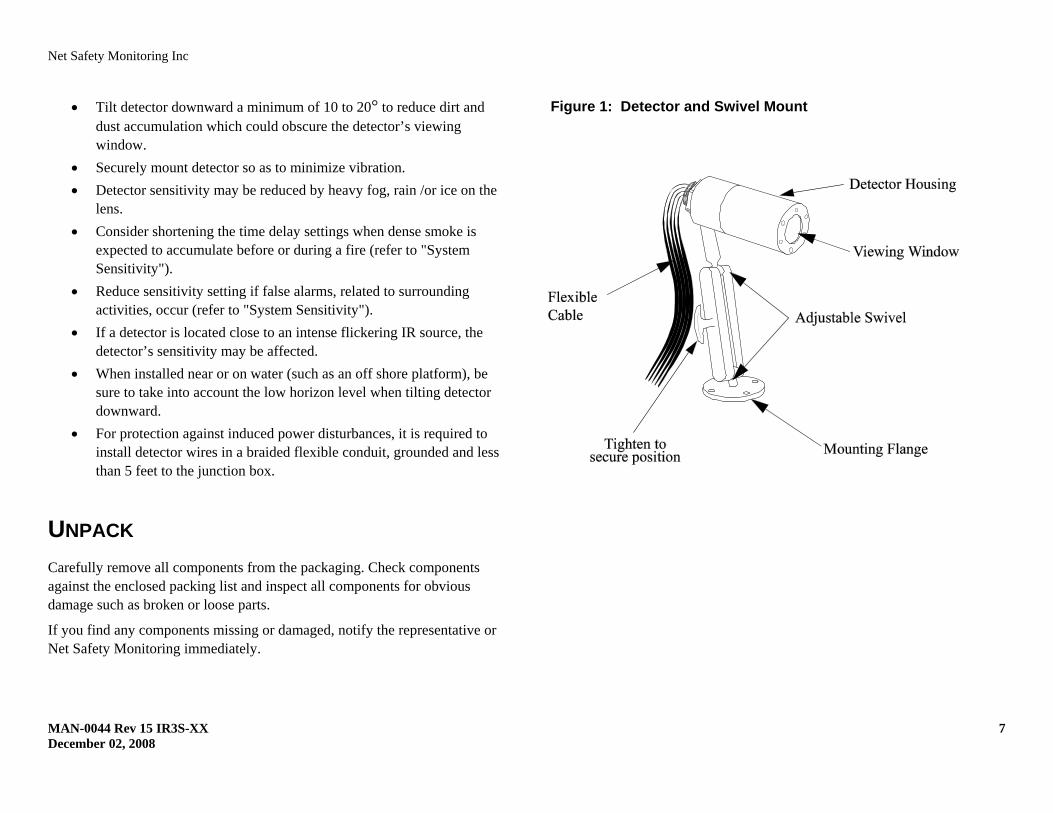
• Tilt detector downward a minimum of 10 to 20° to reduce dirt and dust accumulation which could obscure the detector’s viewing window.
• Securely mount detector so as to minimize vibration. • Detector sensitivity may be reduced by heavy fog, rain /or ice on the
lens. • Consider shortening the time delay settings when dense smoke is
expected to accumulate before or during a fire (refer to "System Sensitivity").
• Reduce sensitivity setting if false alarms, related to surrounding activities, occur (refer to "System Sensitivity").
• If a detector is located close to an intense flickering IR source, the detector’s sensitivity may be affected.
• When installed near or on water (such as an off shore platform), be sure to take into account the low horizon level when tilting detector downward.
• For protection against induced power disturbances, it is required to install detector wires in a braided flexible conduit, grounded and less than 5 feet to the junction box.
UNPACK Carefully remove all components from the packaging. Check components against the enclosed packing list and inspect all components for obvious damage such as broken or loose parts.
If you find any components missing or damaged, notify the representative or Net Safety Monitoring immediately.
Figure 1: Detector and Swivel Mount
Net Safety Monitoring Inc
MAN-0044 Rev 15 IR3S-XX 8 December 02, 2008
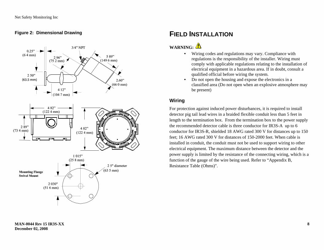
Figure 2: Dimensional Drawing
FIELD INSTALLATION WARNING:
• Wiring codes and regulations may vary. Compliance with regulations is the responsibility of the installer. Wiring must comply with applicable regulations relating to the installation of electrical equipment in a hazardous area. If in doubt, consult a qualified official before wiring the system.
• Do not open the housing and expose the electronics in a classified area (Do not open when an explosive atmosphere may be present)
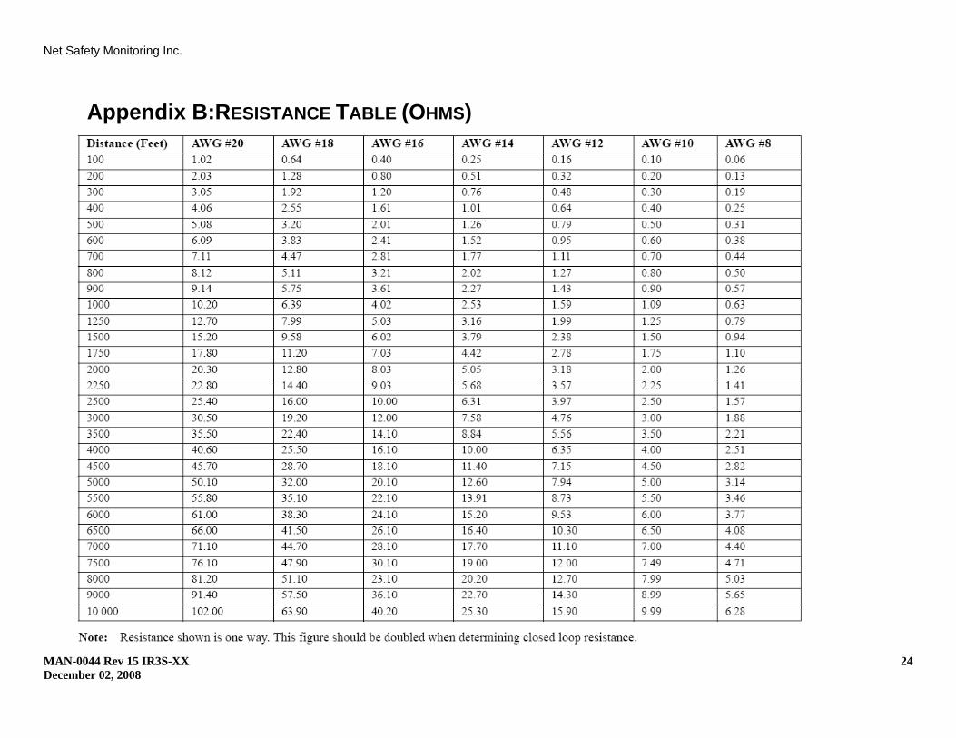
Wiring For protection against induced power disturbances, it is required to install detector pig tail lead wires in a braided flexible conduit less than 5 feet in length to the termination box. From the termination box to the power supply the recommended detector cable is three conductor for IR3S-A up to 6 conductor for IR3S-R, shielded 18 AWG rated 300 V for distances up to 150 feet; 16 AWG rated 300 V for distances of 150-2000 feet. When cable is installed in conduit, the conduit must not be used to support wiring to other electrical equipment. The maximum distance between the detector and the power supply is limited by the resistance of the connecting wiring, which is a function of the gauge of the wire being used. Refer to “Appendix B, Resistance Table (Ohms)".
Net Safety Monitoring Inc
MAN-0044 Rev 15 IR3S-XX 9 December 02, 2008
Grounding Proper shielding and grounding procedures, for the specific area must be followed. Consult local electrical code.
Sealing Water-proof and explosion-proof conduit seals are always recommended to prevent the accumulation of moisture within the junction box. Seals should be located as close to the device as possible and not more than 18 inches (46 cm) away. Explosion-proof installations may require an additional seal where conduit enters a non-hazardous area. When pouring a seal, use a fibre dam to ensure proper formation of the seal. Seals should never be poured at temperatures below freezing.
The jacket and shielding of the cable should be stripped back to permit the seal to form around the individual wires. This will prevent air, gas and water leakage through the inside of the shield and into the enclosure.
It is recommended that explosion-proof drains and conduit breathers be used. Changes in temperature and barometric pressure can cause 'breathing' which allows moist air to enter the conduit. Joints are seldom enough to prevent this 'breathing'.
CONNECTING The Phoenix can be either an Analog, Analog/Digital, Relay or Digital model. Refer to the following tables for specifics regarding connections for the various models. A termination junction box can be also be supplied by Net Safety if required.
WARNING: Prior to wiring, ensure power is disconnected. Improper wiring can cause damage to the detector.
Non-Isolated and Isolated Power Configuration (IR3S-A or IR3S-AD only)
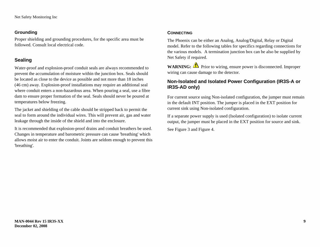
For current source using Non-isolated configuration, the jumper must remain in the default INT position. The jumper is placed in the EXT position for current sink using Non-isolated configuration.
If a separate power supply is used (Isolated configuration) to isolate current output, the jumper must be placed in the EXT position for source and sink.
See Figure 3 and Figure 4.
Net Safety Monitoring Inc
MAN-0044 Rev 15 IR3S-XX 10 December 02, 2008
Figure 3: Current Output Jumper Placement
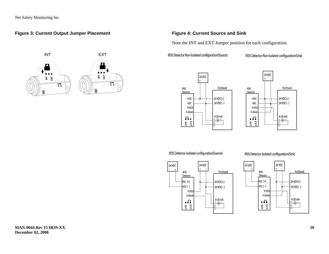
Figure 4: Current Source and Sink
Note the INT and EXT Jumper position for each configuration.
INT EXT
Net Safety Monitoring Inc
MAN-0044 Rev 15 IR3S-XX 11 December 02, 2008
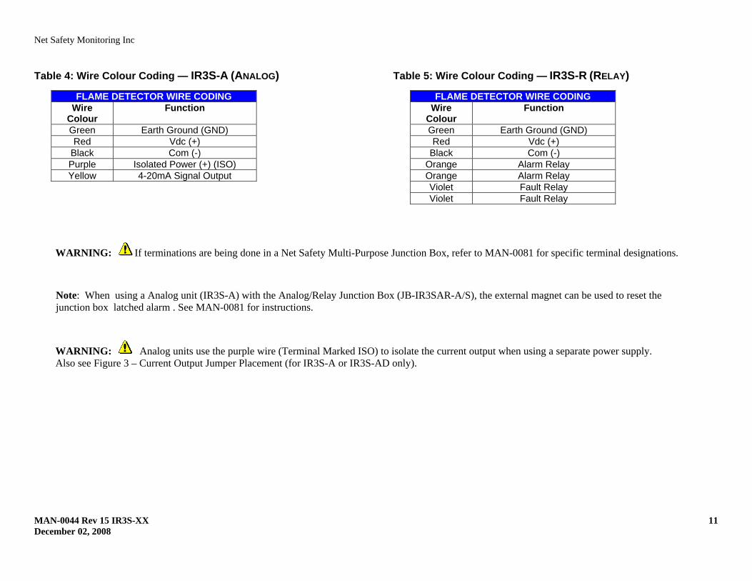
Table 4: Wire Colour Coding — IR3S-A (ANALOG)
FLAME DETECTOR WIRE CODING Wire
Colour Function
Green Earth Ground (GND) Red Vdc (+)
Black Com (-) Purple Isolated Power (+) (ISO) Yellow 4-20mA Signal Output
Table 5: Wire Colour Coding — IR3S-R (RELAY)
FLAME DETECTOR WIRE CODING Wire
Colour Function
Green Earth Ground (GND) Red Vdc (+)
Black Com (-) Orange Alarm Relay Orange Alarm Relay Violet Fault Relay Violet Fault Relay
WARNING: Analog units use the purple wire (Terminal Marked ISO) to isolate the current output when using a separate power supply. Also see Figure 3 – Current Output Jumper Placement (for IR3S-A or IR3S-AD only).
WARNING: If terminations are being done in a Net Safety Multi-Purpose Junction Box, refer to MAN-0081 for specific terminal designations.
Note: When using a Analog unit (IR3S-A) with the Analog/Relay Junction Box (JB-IR3SAR-A/S), the external magnet can be used to reset the junction box latched alarm . See MAN-0081 for instructions.
Net Safety Monitoring Inc
MAN-0044 Rev 15 IR3S-XX 12 December 02, 2008
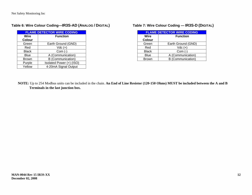
Table 6: Wire Colour Coding—IR3S-AD (ANALOG / DIGITAL)
FLAME DETECTOR WIRE CODING Wire
Colour Function
Green Earth Ground (GND) Red Vdc (+)
Black Com (-) Blue A (Communication)
Brown B (Communication) Purple Isolated Power (+) (ISO) Yellow 4-20mA Signal Output
Table 7: Wire Colour Coding — IR3S-D (DIGITAL)
FLAME DETECTOR WIRE CODING Wire
Colour Function
Green Earth Ground (GND) Red Vdc (+)
Black Com (-) Blue A (Communication)
Brown B (Communication)
NOTE: Up to 254 Modbus units can be included in the chain. An End of Line Resistor (120-150 Ohms) MUST be included between the A and B
Terminals in the last junction box.
Net Safety Monitoring Inc
MAN-0044 Rev 15 IR3S-XX 13 December 02, 2008
DETECTOR SETUP SYSTEM SENSITIVITY Important Fire Sensitivity Considerations The desired fire performance standard is to always respond quickly to a real fire and never respond to a false alarm condition. The best performance is obtained through user adjustments to meet the specific application conditions. Some applications such as the interior of a storage warehouse may have very little infrared or thermal activity and therefore allow the use of full sensitivity and low time delay settings. Applications exposed to intense sunlight reflected from metallic surfaces or water, hot process bodies, exhaust pipes and flare stacks, may require custom combinations of sensitivity and time delay settings. It is recommended that initial settings be low sensitivity and 5 second time delay. If false alarms occur, change the time delay to 10 seconds. If false alarms continue, consult the factory for other recommendations, such as Field of View restrictor. If there are no false alarms after a trial period at the above settings and it is important to alarm on very small or distant fires, then change sensitivity setting to high. If there are still no false alarms and an alarm response to short term transient fire conditions is required, reduce time delay to 3 seconds. A time delay of zero can only be considered in very controlled applications where instantaneous response is necessary and if there is a tolerance for possible false alarms.
Time Delay Settings of 3, 5 and 10 seconds The time delay setting defines the length of time that a fire signal must be continuously present for the detector to output a fire alarm. After the fire has persisted for the set delay time, the alarm output will occur within 5 seconds. This secondary delay of up to 5 seconds is not user adjustable.
Sensitivity Setting
The adjustable Sensitivity setting is used to optimize the Phoenix for a particular application.
When selecting Low or High Sensitivity, consider the following:
- Size of potential fire - Distance between possible fire and detector - Type of flammable substance to be detected - Environmental factors
Response time can vary depending on the intensity and type of fire.
See Table 8 for Time Delay and Sensitivity settings.
DIP Switch Access
DIP Switches are used to define various functional settings and are located on the internal electronics module of the Phoenix. Simply slide a DIP Switch to the ON or OFF position (as marked in Figure 5). Also refer to Table 8 for DIP Switch positioning instructions.
WARNING: Do not open the fire head in a classified area. The area must be de-classified prior to opening the fire head. When open, keep water away from electronics.
WARNING: Do not touch internal components other than the DIP Switches (refer to Appendix A, Electrostatic Sensitive Device (ESD).
Net Safety Monitoring Inc
MAN-0044 Rev 15 IR3S-XX 14 December 02, 2008
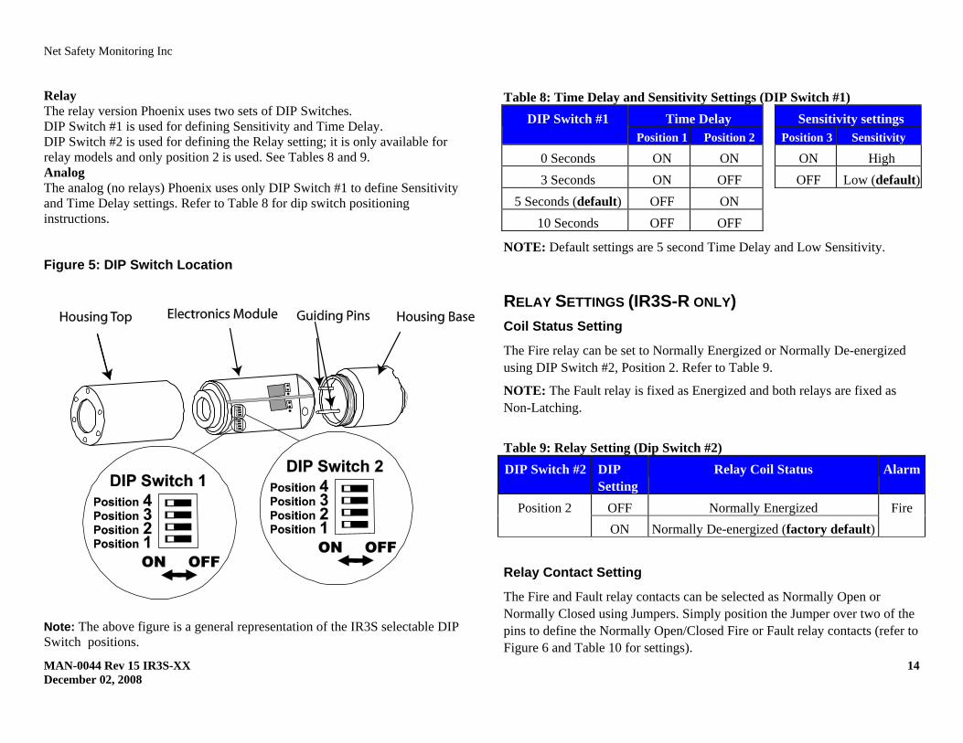
Relay The relay version Phoenix uses two sets of DIP Switches. DIP Switch #1 is used for defining Sensitivity and Time Delay. DIP Switch #2 is used for defining the Relay setting; it is only available for relay models and only position 2 is used. See Tables 8 and 9. Analog The analog (no relays) Phoenix uses only DIP Switch #1 to define Sensitivity and Time Delay settings. Refer to Table 8 for dip switch positioning instructions.
Figure 5: DIP Switch Location Note: The above figure is a general representation of the IR3S selectable DIP Switch positions.
Table 8: Time Delay and Sensitivity Settings (DIP Switch #1) DIP Switch #1 Time Delay Sensitivity settings
Position 1 Position 2 Position 3 Sensitivity
0 Seconds ON ON ON High 3 Seconds ON OFF OFF Low (default)
5 Seconds (default) OFF ON 10 Seconds OFF OFF
NOTE: Default settings are 5 second Time Delay and Low Sensitivity.
RELAY SETTINGS (IR3S-R ONLY) Coil Status Setting
The Fire relay can be set to Normally Energized or Normally De-energized using DIP Switch #2, Position 2. Refer to Table 9.
NOTE: The Fault relay is fixed as Energized and both relays are fixed as Non-Latching.
Table 9: Relay Setting (Dip Switch #2) DIP Switch #2 DIP
Setting Relay Coil Status Alarm
Position 2 OFF Normally Energized Fire ON Normally De-energized (factory default)
Relay Contact Setting
The Fire and Fault relay contacts can be selected as Normally Open or Normally Closed using Jumpers. Simply position the Jumper over two of the pins to define the Normally Open/Closed Fire or Fault relay contacts (refer to Figure 6 and Table 10 for settings).
Net Safety Monitoring Inc
MAN-0044 Rev 15 IR3S-XX 15 December 02, 2008
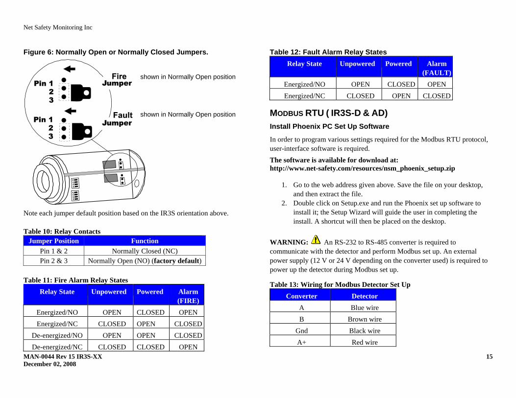
Figure 6: Normally Open or Normally Closed Jumpers.
Note each jumper default position based on the IR3S orientation above. Table 10: Relay Contacts
Jumper Position Function Pin 1 & 2 Normally Closed (NC) Pin 2 & 3 Normally Open (NO) (factory default)
Table 11: Fire Alarm Relay States
Relay State
Unpowered Powered Alarm (FIRE)
Energized/NO OPEN CLOSED OPEN Energized/NC CLOSED OPEN CLOSED
De-energized/NO OPEN OPEN CLOSEDDe-energized/NC CLOSED CLOSED OPEN
Table 12: Fault Alarm Relay States Relay State
Unpowered Powered Alarm
(FAULT)Energized/NO OPEN CLOSED OPEN Energized/NC CLOSED OPEN CLOSED
MODBUS RTU ( IR3S-D & AD) Install Phoenix PC Set Up Software
In order to program various settings required for the Modbus RTU protocol, user-interface software is required. The software is available for download at: http://www.net-safety.com/resources/nsm_phoenix_setup.zip
1. Go to the web address given above. Save the file on your desktop, and then extract the file.
2. Double click on Setup.exe and run the Phoenix set up software to install it; the Setup Wizard will guide the user in completing the install. A shortcut will then be placed on the desktop.
WARNING: An RS-232 to RS-485 converter is required to communicate with the detector and perform Modbus set up. An external power supply (12 V or 24 V depending on the converter used) is required to power up the detector during Modbus set up.
Table 13: Wiring for Modbus Detector Set Up Converter Detector
A Blue wire B Brown wire
Gnd Black wire A+ Red wire
shown in Normally Open position
shown in Normally Open position
Net Safety Monitoring Inc
MAN-0044 Rev 15 IR3S-XX 16 December 02, 2008
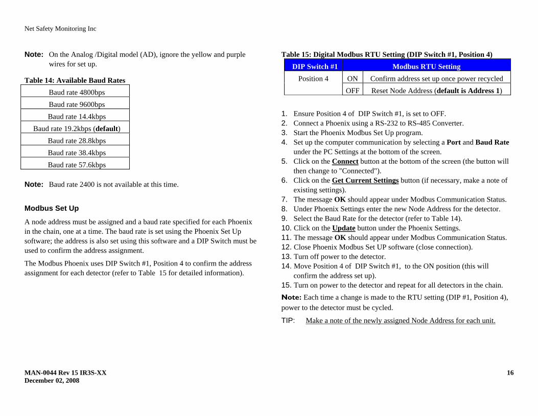
Note: On the Analog /Digital model (AD), ignore the yellow and purple wires for set up.
Table 14: Available Baud Rates Baud rate 4800bps Baud rate 9600bps Baud rate 14.4kbps
Baud rate 19.2kbps (default) Baud rate 28.8kbps Baud rate 38.4kbps Baud rate 57.6kbps
Note: Baud rate 2400 is not available at this time.
Modbus Set Up
A node address must be assigned and a baud rate specified for each Phoenix in the chain, one at a time. The baud rate is set using the Phoenix Set Up software; the address is also set using this software and a DIP Switch must be used to confirm the address assignment.
The Modbus Phoenix uses DIP Switch #1, Position 4 to confirm the address assignment for each detector (refer to Table 15 for detailed information).
Table 15: Digital Modbus RTU Setting (DIP Switch #1, Position 4) DIP Switch #1 Modbus RTU Setting
Position 4 ON Confirm address set up once power recycled OFF Reset Node Address (default is Address 1)
1. Ensure Position 4 of DIP Switch #1, is set to OFF. 2. Connect a Phoenix using a RS-232 to RS-485 Converter. 3. Start the Phoenix Modbus Set Up program. 4. Set up the computer communication by selecting a Port and Baud Rate
under the PC Settings at the bottom of the screen. 5. Click on the Connect button at the bottom of the screen (the button will
then change to "Connected"). 6. Click on the Get Current Settings button (if necessary, make a note of
existing settings). 7. The message OK should appear under Modbus Communication Status. 8. Under Phoenix Settings enter the new Node Address for the detector. 9. Select the Baud Rate for the detector (refer to Table 14). 10. Click on the Update button under the Phoenix Settings. 11. The message OK should appear under Modbus Communication Status. 12. Close Phoenix Modbus Set UP software (close connection). 13. Turn off power to the detector. 14. Move Position 4 of DIP Switch #1, to the ON position (this will
confirm the address set up). 15. Turn on power to the detector and repeat for all detectors in the chain. Note: Each time a change is made to the RTU setting (DIP #1, Position 4), power to the detector must be cycled.
TIP: Make a note of the newly assigned Node Address for each unit.
Net Safety Monitoring Inc
MAN-0044 Rev 15 IR3S-XX 17 December 02, 2008
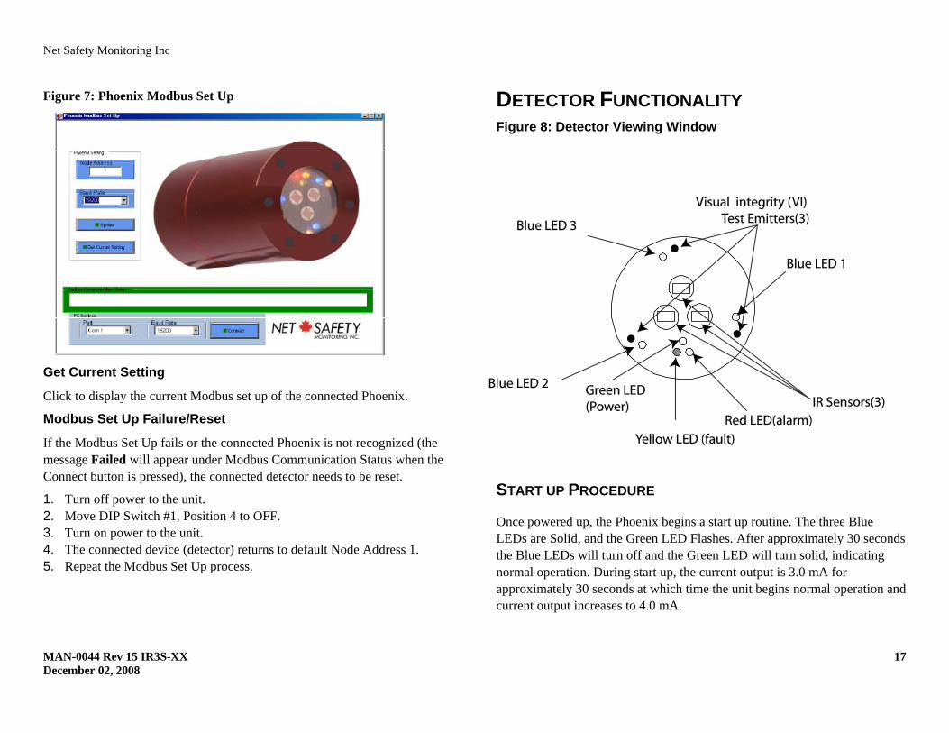
Figure 7: Phoenix Modbus Set Up
Get Current Setting Click to display the current Modbus set up of the connected Phoenix.
Modbus Set Up Failure/Reset If the Modbus Set Up fails or the connected Phoenix is not recognized (the message Failed will appear under Modbus Communication Status when the Connect button is pressed), the connected detector needs to be reset.
1. Turn off power to the unit. 2. Move DIP Switch #1, Position 4 to OFF. 3. Turn on power to the unit. 4. The connected device (detector) returns to default Node Address 1. 5. Repeat the Modbus Set Up process.
DETECTOR FUNCTIONALITY Figure 8: Detector Viewing Window
START UP PROCEDURE
Once powered up, the Phoenix begins a start up routine. The three Blue LEDs are Solid, and the Green LED Flashes. After approximately 30 seconds the Blue LEDs will turn off and the Green LED will turn solid, indicating normal operation. During start up, the current output is 3.0 mA for approximately 30 seconds at which time the unit begins normal operation and current output increases to 4.0 mA.
Net Safety Monitoring Inc
MAN-0044 Rev 15 IR3S-XX 18 December 02, 2008
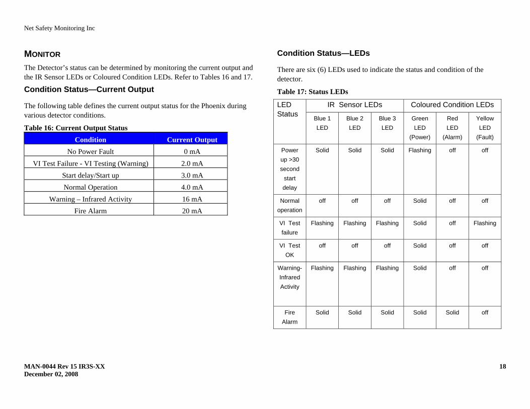
MONITOR The Detector’s status can be determined by monitoring the current output and the IR Sensor LEDs or Coloured Condition LEDs. Refer to Tables 16 and 17.
Condition Status—Current Output
The following table defines the current output status for the Phoenix during various detector conditions.
Table 16: Current Output Status Condition Current Output
No Power Fault 0 mA VI Test Failure - VI Testing (Warning) 2.0 mA
Start delay/Start up 3.0 mA Normal Operation 4.0 mA
Warning – Infrared Activity 16 mA Fire Alarm 20 mA
Condition Status—LEDs
There are six (6) LEDs used to indicate the status and condition of the detector.
Table 17: Status LEDs
LED Status
IR Sensor LEDs Coloured Condition LEDs
Blue 1 LED
Blue 2 LED
Blue 3 LED
Green LED
(Power)
Red LED
(Alarm)
Yellow LED
(Fault)
Power up >30 second
start delay
Solid Solid Solid Flashing off off
Normal operation
off off off Solid off off
VI Test failure
Flashing Flashing Flashing Solid off Flashing
VI Test OK
off off off Solid off off
Warning-Infrared Activity
Flashing Flashing Flashing Solid off off
Fire Alarm
Solid Solid Solid Solid Solid off
Net Safety Monitoring Inc
MAN-0044 Rev 15 IR3S-XX 19 December 02, 2008
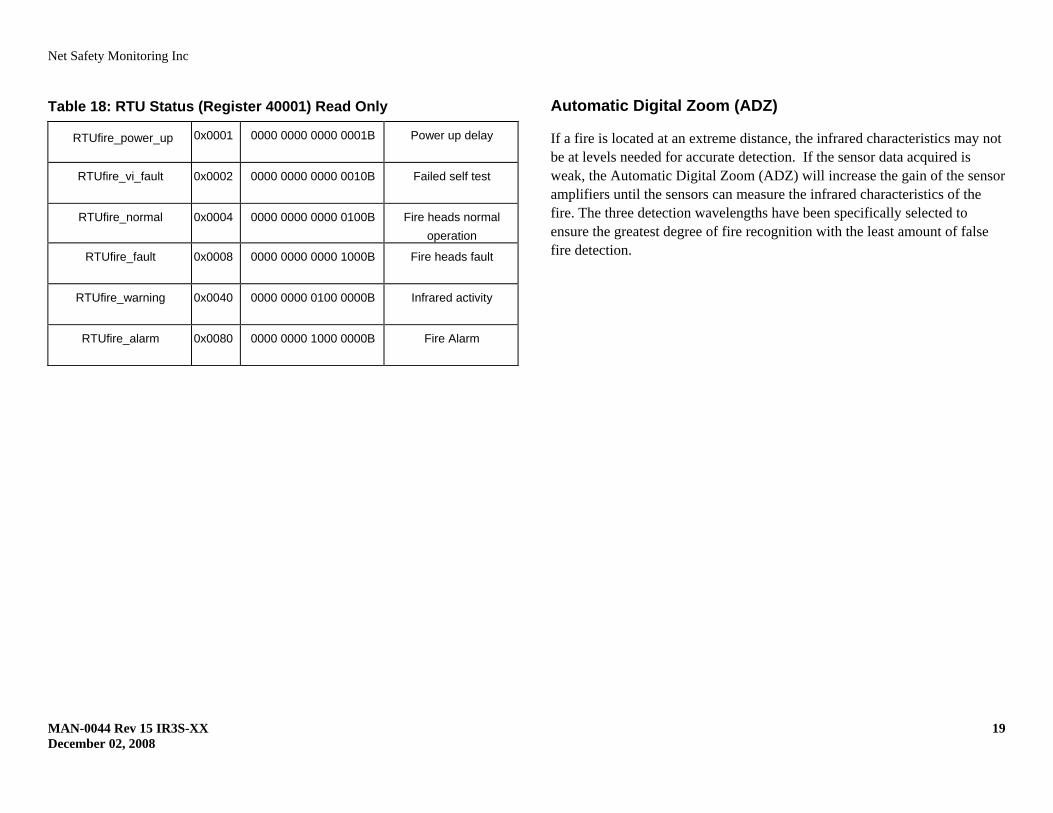
Table 18: RTU Status (Register 40001) Read Only
RTUfire_power_up 0x0001 0000 0000 0000 0001B
Power up delay
RTUfire_vi_fault 0x0002 0000 0000 0000 0010B
Failed self test
RTUfire_normal 0x0004 0000 0000 0000 0100B Fire heads normal operation
RTUfire_fault 0x0008 0000 0000 0000 1000B
Fire heads fault
RTUfire_warning 0x0040 0000 0000 0100 0000B
Infrared activity
RTUfire_alarm 0x0080 0000 0000 1000 0000B
Fire Alarm
Automatic Digital Zoom (ADZ)
If a fire is located at an extreme distance, the infrared characteristics may not be at levels needed for accurate detection. If the sensor data acquired is weak, the Automatic Digital Zoom (ADZ) will increase the gain of the sensor amplifiers until the sensors can measure the infrared characteristics of the fire. The three detection wavelengths have been specifically selected to ensure the greatest degree of fire recognition with the least amount of false fire detection.
Net Safety Monitoring Inc
MAN-0044 Rev 15 IR3S-XX 20 December 02, 2008
TESTING Automatic Visual Integrity (VI) Test
To evaluate the cleanliness of the lens and verify the function of the detection circuits, the Phoenix performs an automatic Visual Integrity (VI) test every 3 minutes.
If accumulation of material on the surface of the lens reaches a factory calibrated preset level, which could substantially reduce flame detection sensitivity, the Phoenix will transmit a VI fault signal indicating that the cause of the fault should be investigated and, if necessary, the window cleaned. Refer to Table 19 for fault types and possible solutions.
Note: Unusual heavy oil accumulations may not be easily detected by the internal VI Test, but are easily identified by an observer during regular inspections.
MAINTAIN
Monitoring the VI fault signal is only part of the necessary routine to ensure the safe operating condition of the detector. If conditions exist, whereby foreign materials could accumulate on the detector’s lens, maintenance routines should include regular visual inspection of the detector and cleaning when necessary, by qualified personnel.
Clean The Window/Lens
WARNING: Always bypass Alarm Output and disconnect external response equipment when performing cleaning and maintenance tasks.
When cleaning the window/lens, use the cloth and the cleaning solution provided with the detector. Use only the cleaning solution provided, as some cleaners may leave a residue or film that blocks IR radiation.
O-ring
The rubber o-ring on the detector housing is used to ensure the detector is watertight. The housing should be opened periodically and the o-ring inspected for breaks, cracks or dryness. To test the o-ring, remove it from the detector housing and stretch it slightly. If cracks are visible, the o-ring should be replaced. If it feels dry to the touch, a thin coating of lubricant should be applied (such as polyalphaolefin grease). When re-installing the o-ring, be sure that it is properly seated in the groove on the housing.
The o-ring must be properly installed and in good condition to prevent water from entering the detector and causing failure. The life expectancy of rubber o- rings varies depending on the type and amount of contaminants present in the area. The person who maintains the system must rely on experience and common sense to determine how frequent the rings should be inspected. A coating of lubricant should also be applied to the enclosure threads before reassembling the detector to help prevent moisture from entering.
Net Safety Monitoring Inc
MAN-0044 Rev 15 IR3S-XX 21 December 02, 2008
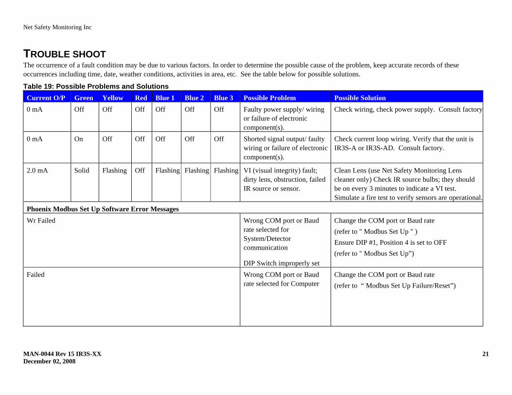
TROUBLE SHOOT The occurrence of a fault condition may be due to various factors. In order to determine the possible cause of the problem, keep accurate records of these occurrences including time, date, weather conditions, activities in area, etc. See the table below for possible solutions.
Table 19: Possible Problems and Solutions Current O/P Green Yellow Red Blue 1 Blue 2 Blue 3 Possible Problem Possible Solution 0 mA Off Off Off Off Off Off Faulty power supply/ wiring
or failure of electronic component(s).
Check wiring, check power supply. Consult factory
0 mA On Off Off Off Off Off Shorted signal output/ faulty wiring or failure of electronic component(s).
Check current loop wiring. Verify that the unit is IR3S-A or IR3S-AD. Consult factory.
2.0 mA Solid Flashing Off Flashing Flashing Flashing VI (visual integrity) fault; dirty lens, obstruction, failed IR source or sensor.
Clean Lens (use Net Safety Monitoring Lens cleaner only) Check IR source bulbs; they should be on every 3 minutes to indicate a VI test. Simulate a fire test to verify sensors are operational.
Phoenix Modbus Set Up Software Error Messages Wr Failed
Wrong COM port or Baud rate selected for System/Detector communication
DIP Switch improperly set
Change the COM port or Baud rate (refer to " Modbus Set Up " ) Ensure DIP #1, Position 4 is set to OFF (refer to " Modbus Set Up”)
Failed Wrong COM port or Baud rate selected for Computer
Change the COM port or Baud rate (refer to “ Modbus Set Up Failure/Reset”)
Net Safety Monitoring Inc
MAN-0044 Rev 15 IR3S-XX 22 December 02, 2008
HOW TO RETURN EQUIPMENT A Material Return Authorization number is required in order to return equipment. Please contact Net Safety Monitoring at (403) 219-0688 before returning equipment or consult our Service Department to possibly avoid returning equipment.
If you are required to return equipment, include the following information:
1. A Material Return Authorization number (provided over the phone to you by Net Safety).
2. A detailed description of the problem. The more specific you are regarding the problem, the quicker our Service department can determine and correct the problem.
3. A company name, contact name and telephone number. 4. A Purchase Order, from your company, authorizing repairs or request for
quote. 5. Ship all equipment, prepaid to:
Net Safety Monitoring Inc 2721 Hopewell Place NE Calgary, Alberta, Canada T1Y 7J7
6. Mark all packages: RETURN for REPAIR
Waybills, for shipments from outside Canada, must state: Equipment being returned for repair All charges to be billed to the sender
Also, please ensure a duplicate copy of the packing slip is enclosed inside the box indicating item 1-4 along with the courier and account number for returning the goods.
All Equipment must be Shipped prepaid. Collect shipments will not be accepted.
Pack items to protect them from damage and use anti-static bags or aluminum- backed cardboard as protection from electrostatic discharge.
Net Safety Monitoring Inc
MAN-0044 Rev 15 IR3S-XX 23 December 02, 2008
Appendix A:ELECTROSTATIC SENSITIVE DEVICE (ESD) Electrostatic discharge (ESD) is the transfer, between bodies, of an electrostatic charge caused by direct contact or induced by an electrostatic field.
The most common cause of ESD is physical contact. Touching an object can cause a discharge of electrostatic energy—ESD! If the charge is sufficient and occurs near electronic components, it can damage or destroy those components.
In some cases, damage is instantaneous and an immediate malfunction occurs. However, symptoms are not always immediate—performance may be marginal or seemingly normal for an indefinite period of time, followed by a sudden failure.
To eliminate potential ESD damage, review the following guidelines:
• Handle boards by metal shields—taking care not to touch electronic components
• Wear grounded wrist or foot straps, or ESD shoes or heel grounders to dissipate unwanted static energy
• Prior to handling boards, dispel any charge in your body or equipment • Ensure components are transported and stored in static safe packaging • When returning boards, carefully package in the original carton and static
protective wrapping • Ensure ALL personnel are educated and trained in ESD Control
Procedures
In general, exercise accepted and proven precautions normally observed when handling electrostatic sensitive devices.
A warning label is placed on the packaging, identifying product using electrostatic sensitive semiconductor devices.
Net Safety Monitoring Inc.
MAN-0044 Rev 15 IR3S-XX 24 December 02, 2008
Appendix B:RESISTANCE TABLE (OHMS)
Net Safety
MAN-004Decembe
A
N
y Monitoring Inc
44 Rev 15 IR3S-Xer 02, 2008
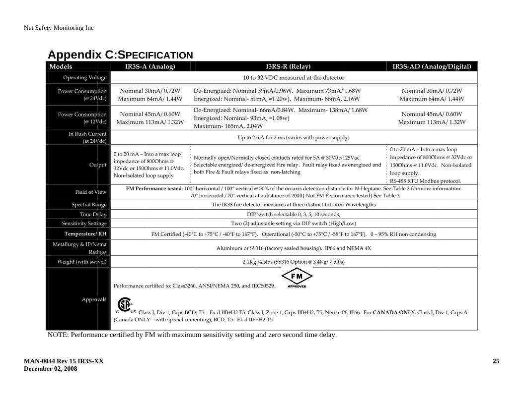
AppendixModels
Operating Volt
Power Consumpt(@ 24V
Power Consumpt(@ 12V
In Rush Curr(at 24V
Out
Field of V
Spectral Ra
Time De
Sensitivity Setti
Temperature/
Metallurgy & IP/NeRati
Weight (with swi
Approv
NOTE: Performa
XX
x C:SPECIIR3S‐A
tage
tion Vdc)
Nominal 3Maximum
tion Vdc)
Nominal 4Maximum 1
rent Vdc)
tput
0 to 20 mA – Inimpedance of 32Vdc or 150ONon‐Isolated l
View FM Perfo
ange
elay
ings
RH
ema ings
vel)
vals
Performance c
Cla(Canada ONLY
ance certified by F
IFICATIONA (Analog)
30mA/ 0.72W 64mA/ 1.44W
DE
45mA/ 0.60W 113mA/ 1.32W
DEM
nto a max loop 800Ohms @ Ohms @ 11.0Vdc. loop supply
NSb
ormance tested: 100° 70
FM Certified (‐40°C
certified to: Class3260
ss I, Div 1, Grps BCDY – with special ceme
FM with maximu
1
De‐Energized: NomEnergized: Nomina
De‐Energized: NomEnergized: NominaMaximum‐ 165mA,
Up
Normally open/NormSelectable energized/ both Fire & Fault relay
horizontal / 100° vert0° horizontal / 70° vert
The IR3S fire d
Two (
C to +75°C / ‐40°F to 1
Aluminum o
2
, ANSI/NEMA 250, a
D, T5. Ex d IIB+H2 T5enting), BCD, T5. Ex
um sensitivity sett
I3RS‐R (R10 to 32 VDC measu
minal 39mA/0.96W.al‐ 51mA, =1.20w).
minal‐ 66mA/0.84Wal‐ 93mA, =1.08w) , 2.04W
p to 2.6 A for 2.ms (va
mally closed contacts rde‐energized Fire relays fixed as non‐latchi
tical @ 50% of the on‐atical at a distance of 2
detector measures at t
DIP switch selectabl
(2) adjustable setting v
67°F). Operational (‐
or SS316 (factory seal
2.1Kg /4.5lbs (SS316 O
nd IEC60529.
5. Class I, Zone 1, Grpd IIB+H2 T5.
ting and zero seco
Relay) ured at the detecto
Maximum 73mA/Maximum‐ 86mA,
W. Maximum‐ 138m
aries with power supp
rated for 5A @ 30Vdc/ay. Fault relay fixed ing
axis detection distanc200ft( Not FM Perform
three distinct Infrared
le 0, 3, 5, 10 seconds,
via DIP switch (High
‐50°C to +75°C / ‐58°F
ed housing). IP66 an
Option @ 3.4Kg/ 7.5lbs
ps IIB+H2, T5; Nema 4
ond time delay.
r
/ 1.68W 2.16W
mA/ 1.68W
ply)
/125Vac. as energized and
0i1lR
ce for N‐Heptane. Seemance tested) See Tab
d Wavelengths
h/Low)
F to 167°F). 0 – 95% R
nd NEMA 4X
s)
4X, IP66. For CANAD
IR3S‐AD (Analo
Nominal 30mAMaximum 64m
Nominal 45mAMaximum 113m
0 to 20 mA – Into a mimpedance of 800Ohm150Ohms @ 11.0Vdc. loop supply. RS‐485 RTU Modbus e Table 2 for more infoble 3.
RH non condensing
DA ONLY, Class I, Di
og/Digital)
A/ 0.72W A/ 1.44W
A/ 0.60W mA/ 1.32W
max loop ms @ 32Vdc or Non‐Isolated
protocol. ormation.
iv 1, Grps A
25
Net Safety Monitoring Inc
MAN-0044 Rev 15 IR3S-XX 26 December 02, 2008
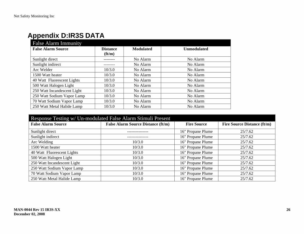
Appendix D:IR3S DATA False Alarm Immunity False Alarm Source Distance
(ft/m) Modulated Unmodulated
Sunlight direct -------- No Alarm No Alarm Sunlight indirect -------- No Alarm No Alarm Arc Welder 10/3.0 No Alarm No Alarm 1500 Watt heater 10/3.0 No Alarm No Alarm 40 Watt Fluorescent Lights 10/3.0 No Alarm No Alarm 500 Watt Halogen Light 10/3.0 No Alarm No Alarm 250 Watt Incandescent Light 10/3.0 No Alarm No Alarm 250 Watt Sodium Vapor Lamp 10/3.0 No Alarm No Alarm 70 Watt Sodium Vapor Lamp 10/3.0 No Alarm No Alarm 250 Watt Metal Halide Lamp 10/3.0 No Alarm No Alarm
Response Testing w/ Un-modulated False Alarm Stimuli Present False Alarm Source False Alarm Source Distance (ft/m) Fire Source Fire Source Distance (ft/m)
Sunlight direct --------------- 16" Propane Plume 25/7.62 Sunlight indirect --------------- 16" Propane Plume 25/7.62 Arc Welding 10/3.0 16" Propane Plume 25/7.62 1500 Watt heater 10/3.0 16" Propane Plume 25/7.62 40 Watt Fluorescent Lights 10/3.0 16" Propane Plume 25/7.62 500 Watt Halogen Light 10/3.0 16" Propane Plume 25/7.62 250 Watt Incandescent Light 10/3.0 16" Propane Plume 25/7.62 250 Watt Sodium Vapor Lamp 10/3.0 16" Propane Plume 25/7.62 70 Watt Sodium Vapor Lamp 10/3.0 16" Propane Plume 25/7.62 250 Watt Metal Halide Lamp 10/3.0 16" Propane Plume 25/7.62
Net Safety Monitoring Inc
MAN-0044 Rev 15 IR3S-XX 27 December 02, 2008
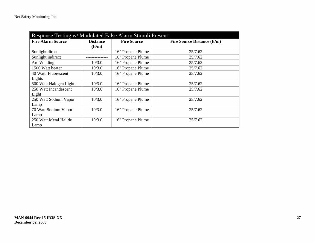
Response Testing w/ Modulated False Alarm Stimuli Present Fire Alarm Source Distance
(ft/m) Fire Source Fire Source Distance (ft/m)
Sunlight direct --------------- 16" Propane Plume 25/7.62 Sunlight indirect --------------- 16" Propane Plume 25/7.62 Arc Welding 10/3.0 16" Propane Plume 25/7.62 1500 Watt heater 10/3.0 16" Propane Plume 25/7.62 40 Watt Fluorescent Lights
10/3.0 16" Propane Plume 25/7.62
500 Watt Halogen Light 10/3.0 16" Propane Plume 25/7.62 250 Watt Incandescent Light
10/3.0 16" Propane Plume 25/7.62
250 Watt Sodium Vapor Lamp
10/3.0 16" Propane Plume 25/7.62
70 Watt Sodium Vapor Lamp
10/3.0 16" Propane Plume 25/7.62
250 Watt Metal Halide Lamp
10/3.0 16" Propane Plume 25/7.62

Net Safety Monitoring Inc. 2721 Hopewell Place NE, Calgary, AB Canada T1Y 7J7 1‐866‐FIREGAS (347‐3427) | ph. (403) 219‐0688 | fx. (403) 219‐0694 http://www.net‐safety.com | Email: nsmsales@net‐safety.com
PRODUCT SERVICES CONTACT INFORMATION Telephone [ 8am ‐ 5pm MDT ]: (403) 769‐6074 | (403) 717‐8219 Fax: (403) 219‐0694 Email: productservices@net‐safety.com http://www.net‐safety.com/service/product_services.html