Embed Size (px)
Citation preview
PHOBOS N BT & PHOBOS NL BT
INSTALLER REFERENCEVERSION 101115
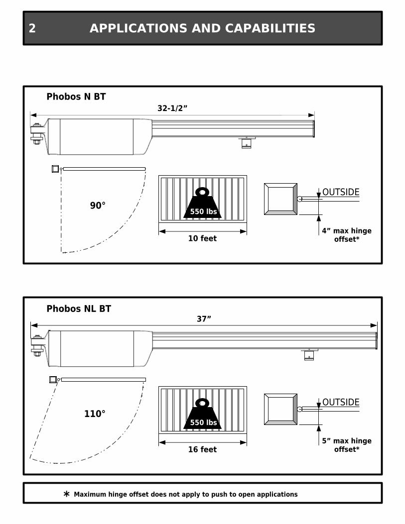
550 lbs
10 feet
90°
Phobos N BT
110°
Phobos NL BT
16 feet
550 lbs
OUTSIDE
4” max hingeoffset*
OUTSIDE
5” max hingeoffset*
32-1/2”
37”
APPLICATIONS AND CAPABILITIES2
* Maximum hinge offset does not apply to push to open applications
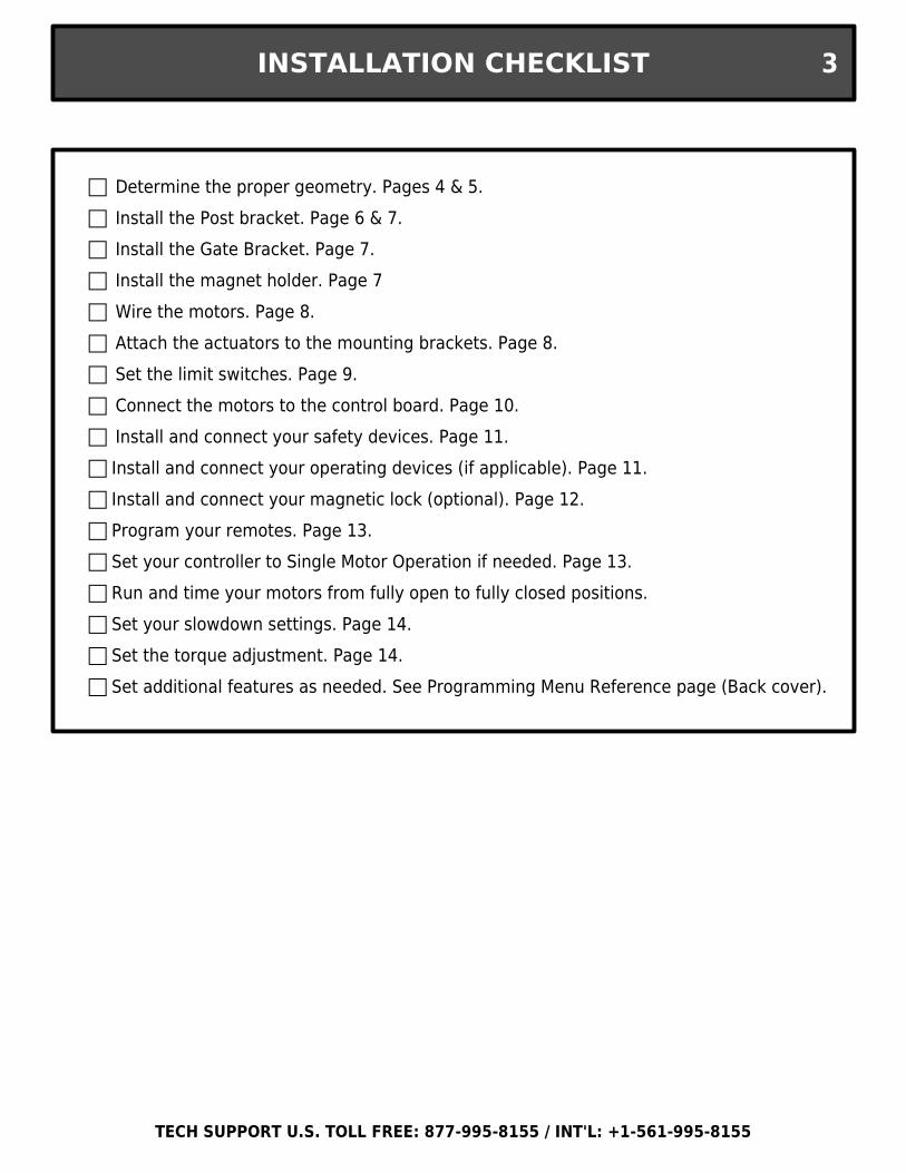
INSTALLATION CHECKLIST 3
Determine the proper geometry. Pages 4 & 5. Install the Post bracket. Page 6 & 7. Install the Gate Bracket. Page 7. Install the magnet holder. Page 7 Wire the motors. Page 8. Attach the actuators to the mounting brackets. Page 8. Set the limit switches. Page 9. Connect the motors to the control board. Page 10. Install and connect your safety devices. Page 11. Install and connect your operating devices (if applicable). Page 11. Install and connect your magnetic lock (optional). Page 12. Program your remotes. Page 13. Set your controller to Single Motor Operation if needed. Page 13. Run and time your motors from fully open to fully closed positions. Set your slowdown settings. Page 14. Set the torque adjustment. Page 14. Set additional features as needed. See Programming Menu Reference page (Back cover).
TECH SUPPORT U.S. TOLL FREE: 877-995-8155 / INT'L: +1-561-995-8155
A
B
A
90°90°B
90°90°
PIVOT POINT
PIVO
T PO
INT
PHOBOS' PIVOT POINT
Gate hinge
Gate frameGate post
C
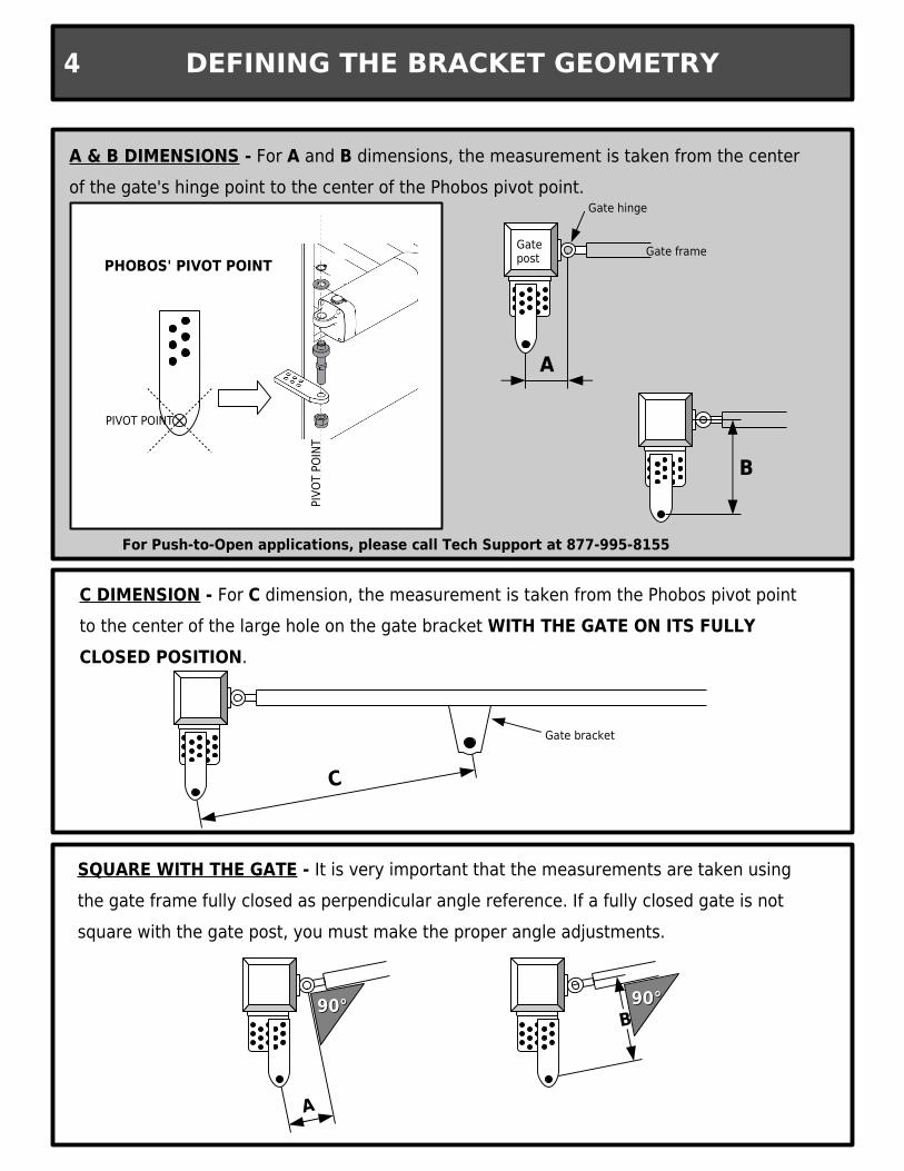
C DIMENSION - For C dimension, the measurement is taken from the Phobos pivot point to the center of the large hole on the gate bracket WITH THE GATE ON ITS FULLY CLOSED POSITION.
Gate bracket
A & B DIMENSIONS - For A and B dimensions, the measurement is taken from the center of the gate's hinge point to the center of the Phobos pivot point.
SQUARE WITH THE GATE - It is very important that the measurements are taken using the gate frame fully closed as perpendicular angle reference. If a fully closed gate is not square with the gate post, you must make the proper angle adjustments.
DEFINING THE BRACKET GEOMETRY4
For Push-to-Open applications, please call Tech Support at 877-995-8155
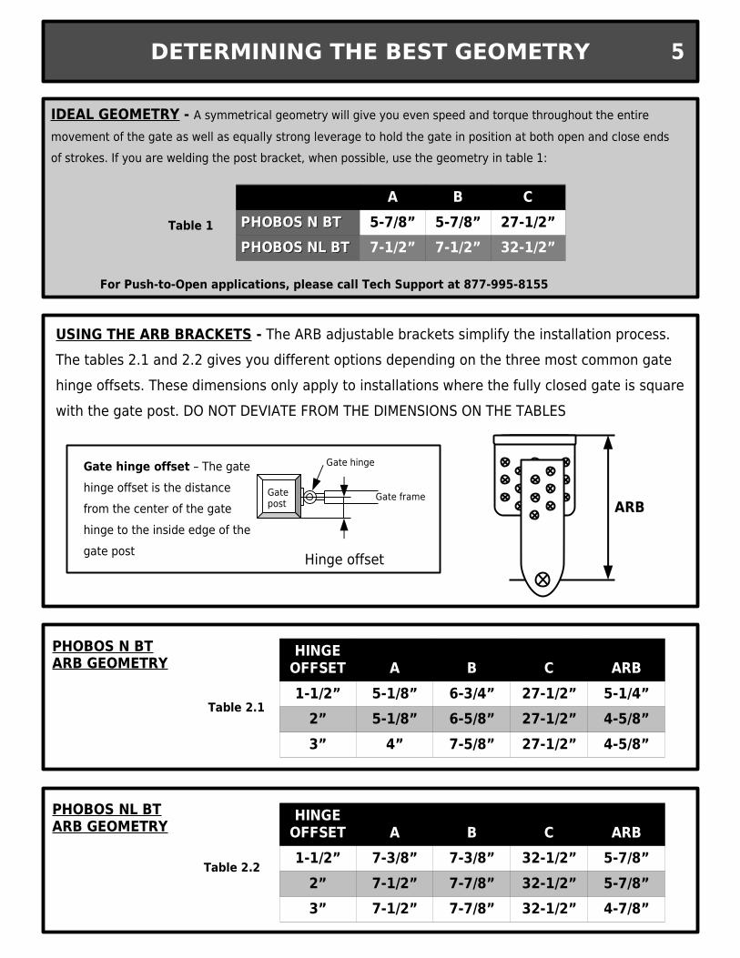
Table 2.1
IDEAL GEOMETRY - A symmetrical geometry will give you even speed and torque throughout the entire movement of the gate as well as equally strong leverage to hold the gate in position at both open and close ends of strokes. If you are welding the post bracket, when possible, use the geometry in table 1:
Table 1
USING THE ARB BRACKETS - The ARB adjustable brackets simplify the installation process. The tables 2.1 and 2.2 gives you different options depending on the three most common gate hinge offsets. These dimensions only apply to installations where the fully closed gate is square with the gate post. DO NOT DEVIATE FROM THE DIMENSIONS ON THE TABLES
Gate hinge
Gate frameGate post
Hinge offset
Gate hinge offset – The gate hinge offset is the distance from the center of the gate hinge to the inside edge of the gate post
ARB
Table 2.2
A B C ARB1-1/2” 5-1/8” 6-3/4” 27-1/2” 5-1/4”
2” 5-1/8” 6-5/8” 27-1/2” 4-5/8”3” 4” 7-5/8” 27-1/2” 4-5/8”
HINGE OFFSET
A B C ARB1-1/2” 7-3/8” 7-3/8” 32-1/2” 5-7/8”
2” 7-1/2” 7-7/8” 32-1/2” 5-7/8”3” 7-1/2” 7-7/8” 32-1/2” 4-7/8”
HINGE OFFSET
PHOBOS N BT ARB GEOMETRY
PHOBOS NL BT ARB GEOMETRY
DETERMINING THE BEST GEOMETRY 5
A B CPHOBOS N BTPHOBOS N BT 5-7/8” 5-7/8” 27-1/2”PHOBOS NL BTPHOBOS NL BT 7-1/2” 7-1/2” 32-1/2”
For Push-to-Open applications, please call Tech Support at 877-995-8155
ARB BRACKET LENGTHS
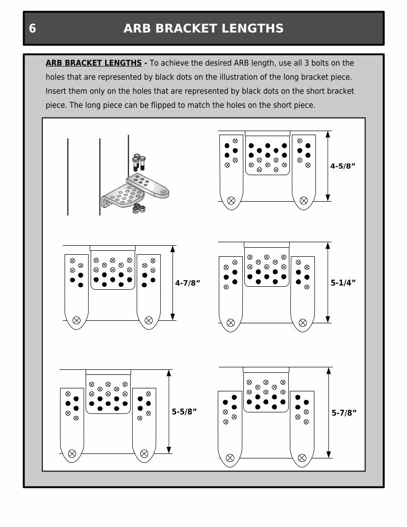
ARB BRACKET LENGTHS - To achieve the desired ARB length, use all 3 bolts on the holes that are represented by black dots on the illustration of the long bracket piece. Insert them only on the holes that are represented by black dots on the short bracket piece. The long piece can be flipped to match the holes on the short piece.
5-5/8”
5-1/4”
5-7/8”
6
3-7/8”
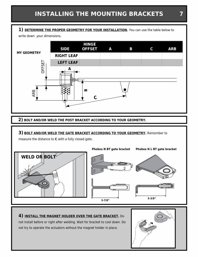
Phobos N BT gate bracket
5-3/8”
Phobos N L BT gate bracket
1) DETERMINE THE PROPER GEOMETRY FOR YOUR INSTALLATION. You can use the table below to write down your dimensions.
3) BOLT AND/OR WELD THE GATE BRACKET ACCORDING TO YOUR GEOMETRY. Remember to measure the distance to C with a fully closed gate.
WELD OR BOLT
4) INSTALL THE MAGNET HOLDER OVER THE GATE BRACKET. Do not install before or right after welding. Wait for bracket to cool down. Do not try to operate the actuators without the magnet holder in place.
2) BOLT AND/OR WELD THE POST BRACKET ACCORDING TO YOUR GEOMETRY.
SIDE A B C ARBRIGHT LEAF
LEFT LEAF
HINGE OFFSET
MY GEOMETRY
INSTALLING THE MOUNTING BRACKETS 7
C
OFFS
ET
ARB
A
B
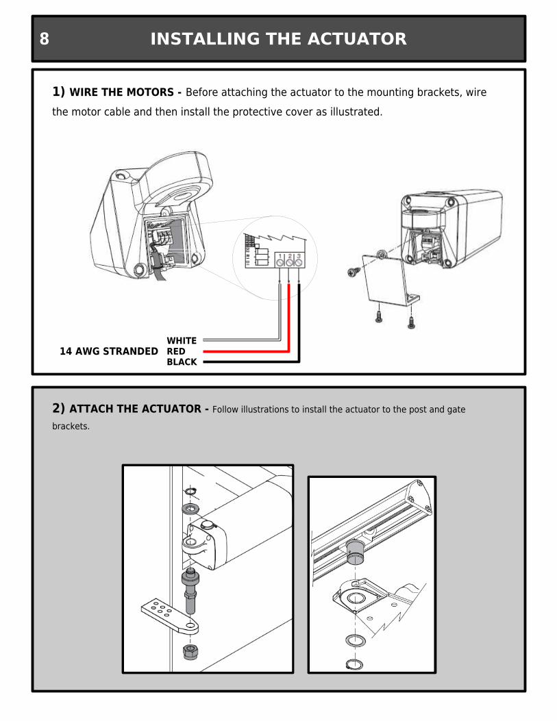
WHITEREDBLACK
14 AWG STRANDED
1) WIRE THE MOTORS - Before attaching the actuator to the mounting brackets, wire the motor cable and then install the protective cover as illustrated.
2) ATTACH THE ACTUATOR - Follow illustrations to install the actuator to the post and gate brackets.
INSTALLING THE ACTUATOR8

1) SET TO MANUAL OPERATION - Disengage the drive gear by using the triangular key and turning clockwise.
2) SET THE CLOSE LIMIT - Push the gate to its fully closed position. Remove the screw that holds the proximity sensor at the front end of the actuator. Slide it back so that the back end of the sensor housing is 3-1/2” from the center of the drive carriage and re-attach screw that secures sensor in place.
3) SET THE OPEN LIMIT - Push the gate to its fully open position. Remove the screw that holds the proximity sensor closest to the actuator body. Slide it forward so that the back end of the sensor housing is 3-1/2” from the center of the drive carriage and re-attach screw that secures sensor in place.
3-1/2”
4) RE-ENGAGE THE MANUAL RELEASE - Use triangular key and turn counterclockwise to re-engage gears.
SETTING THE LIMIT SWITCHES 9
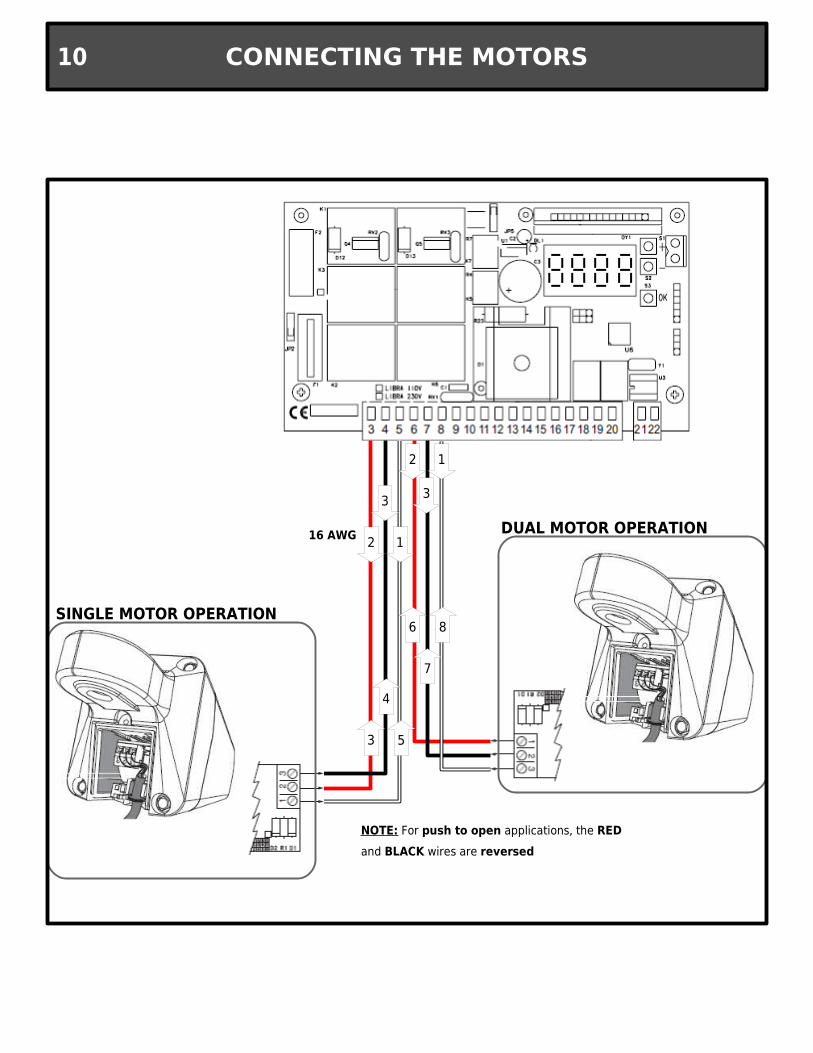
SINGLE MOTOR OPERATION
DUAL MOTOR OPERATION16 AWG
NOTE: For push to open applications, the RED and BLACK wires are reversed
CONNECTING THE MOTORS10
2
3
1
2
3
1
3 5
4
6 8
7
Common 3
1
2
5Normally closed
TRANSMITTER
RECEIVER
1
2 14→
13→ ←12
←11
←15
←18
CONTROL INPUTS 11
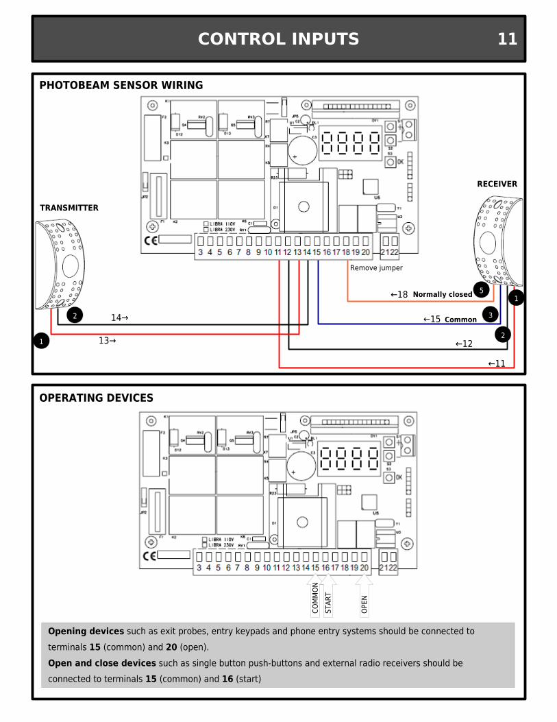
Opening devices such as exit probes, entry keypads and phone entry systems should be connected to terminals 15 (common) and 20 (open).Open and close devices such as single button push-buttons and external radio receivers should be connected to terminals 15 (common) and 16 (start)
PHOTOBEAM SENSOR WIRING
OPERATING DEVICES
COM
MON
STAR
T
OPEN
Remove jumper
Normally closed (Orange)
Common (Blue)
Positive
Negative
EXTERNAL POWER SUPPLYFOR MAGNETIC LOCK
24V AC/DCDouble throw
RelayPart No. KRELAY24V
+ (Red)
- (White)
OTHER CONNECTIONS12
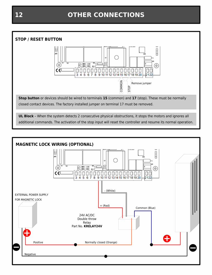
MAGNETIC LOCK WIRING (OPTIONAL)
Stop button or devices should be wired to terminals 15 (common) and 17 (stop). These must be normally closed contact devices. The factory installed jumper on terminal 17 must be removed.
COM
MON
STOP
STOP / RESET BUTTON
Remove jumper
UL Block – When the system detects 2 consecutive physical obstructions, it stops the motors and ignores all additional commands. The activation of the stop input will reset the controller and resume its normal operation.
INITIAL PROGRAMMING 13
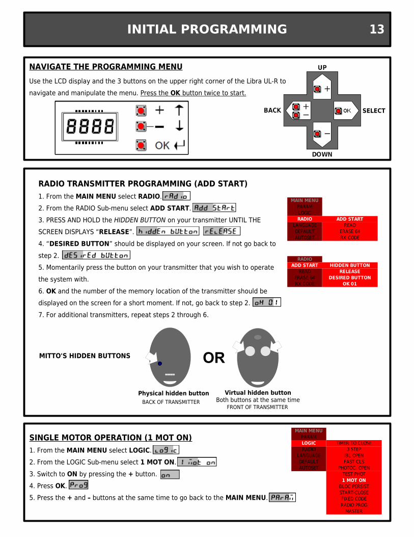
SINGLE MOTOR OPERATION (1 MOT ON)1. From the MAIN MENU select LOGIC.2. From the LOGIC Sub-menu select 1 MOT ON.3. Switch to ON by pressing the + button.4. Press OK.5. Press the + and – buttons at the same time to go back to the MAIN MENU.
MAIN MENUPARAMLOGIC TIMER TO CLOSERADIO 3 STEP
LANGUAGE IBL OPENDEFAULT FAST CLSAUTOSET PHOTOC. OPEN
TEST PHOT1 MOT ON
BLOC PERSISTSTART-CLOSEFIXED CODERADIO PROG
MASTER
MAIN MENUPARAMLOGICRADIO ADD START
LANGUAGE READDEFAULT ERASE 64AUTOSET RX CODE
RADIO TRANSMITTER PROGRAMMING (ADD START)1. From the MAIN MENU select RADIO.2. From the RADIO Sub-menu select ADD START.3. PRESS AND HOLD the HIDDEN BUTTON on your transmitter UNTIL THE SCREEN DISPLAYS “RELEASE”.4. “DESIRED BUTTON” should be displayed on your screen. If not go back to step 2.5. Momentarily press the button on your transmitter that you wish to operate the system with.6. OK and the number of the memory location of the transmitter should be displayed on the screen for a short moment. If not, go back to step 2.7. For additional transmitters, repeat steps 2 through 6.
RADIOADD START HIDDEN BUTTON
READ RELEASEERASE 64 DESIRED BUTTONRX CODE OK 01
BACK OF TRANSMITTERPhysical hidden button
FRONT OF TRANSMITTER
Virtual hidden buttonBoth buttons at the same time
ORMITTO'S HIDDEN BUTTONS
SELECT
Use the LCD display and the 3 buttons on the upper right corner of the Libra UL-R to navigate and manipulate the menu. Press the OK button twice to start.
NAVIGATE THE PROGRAMMING MENU
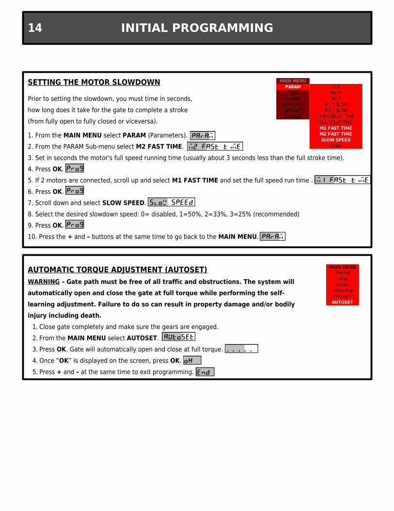
SETTING THE MOTOR SLOWDOWN
1. From the MAIN MENU select PARAM (Parameters).2. From the PARAM Sub-menu select M2 FAST TIME.3. Set in seconds the motor's full speed running time (usually about 3 seconds less than the full stroke time).4. Press OK.5. If 2 motors are connected, scroll up and select M1 FAST TIME and set the full speed run time .6. Press OK.7. Scroll down and select SLOW SPEED.8. Select the desired slowdown speed: 0= disabled, 1=50%, 2=33%, 3=25% (recommended)9. Press OK.10. Press the + and – buttons at the same time to go back to the MAIN MENU.
Prior to setting the slowdown, you must time in seconds, how long does it take for the gate to complete a stroke (from fully open to fully closed or viceversa).
MAIN MENUPARAM TCALOGIC M1 TRADIO M2 T
LANGUAGE M1 T SLOWDEFAULT M2 T SLOWAUTOSET OPEN DELAY TIME
CLS DELAY TIMEM1 FAST TIMEM2 FAST TIMESLOW SPEED
ZONE
AUTOMATIC TORQUE ADJUSTMENT (AUTOSET)WARNING – Gate path must be free of all traffic and obstructions. The system will automatically open and close the gate at full torque while performing the self-learning adjustment. Failure to do so can result in property damage and/or bodily injury including death.
1. Close gate completely and make sure the gears are engaged.2. From the MAIN MENU select AUTOSET.3. Press OK. Gate will automatically open and close at full torque.4. Once “OK” is displayed on the screen, press OK.5. Press + and – at the same time to exit programming.
MAIN MENUPARAMLOGICRADIO
LANGUAGEDEFAULT
AUTOSET
INITIAL PROGRAMMING14
INITIAL PROGRAMMING 15
MAIN MENUPARAMLOGIC TIMER TO CLOSERADIO 3 STEP
LANGUAGE IBL OPENDEFAULT FAST CLSAUTOSET PHOTOC. OPEN
TEST PHOT1 MOT ON
BLOC PERSISTSTART-CLOSEFIXED CODERADIO PROG
MASTER
MAIN MENUPARAMLOGIC TCARADIO 3 STEP
LANGUAGE IBL OPENDEFAULT FAST CLSAUTOSET PHOTOC. OPEN
TEST PHOT1 MOT ON
BLOC PERSISTSTART-CLOSEFIXED CODERADIO PROG
MASTER
MAIN MENUPARAM TCALOGIC M1 TRADIO M2 T
LANGUAGE M1 T SLOWDEFAULT M2 T SLOWAUTOSET OPEN DELAY TIME
CLS DELAY TIMEM1 FAST TIMEM2 FAST TIMESLOW SPEED
ZONE
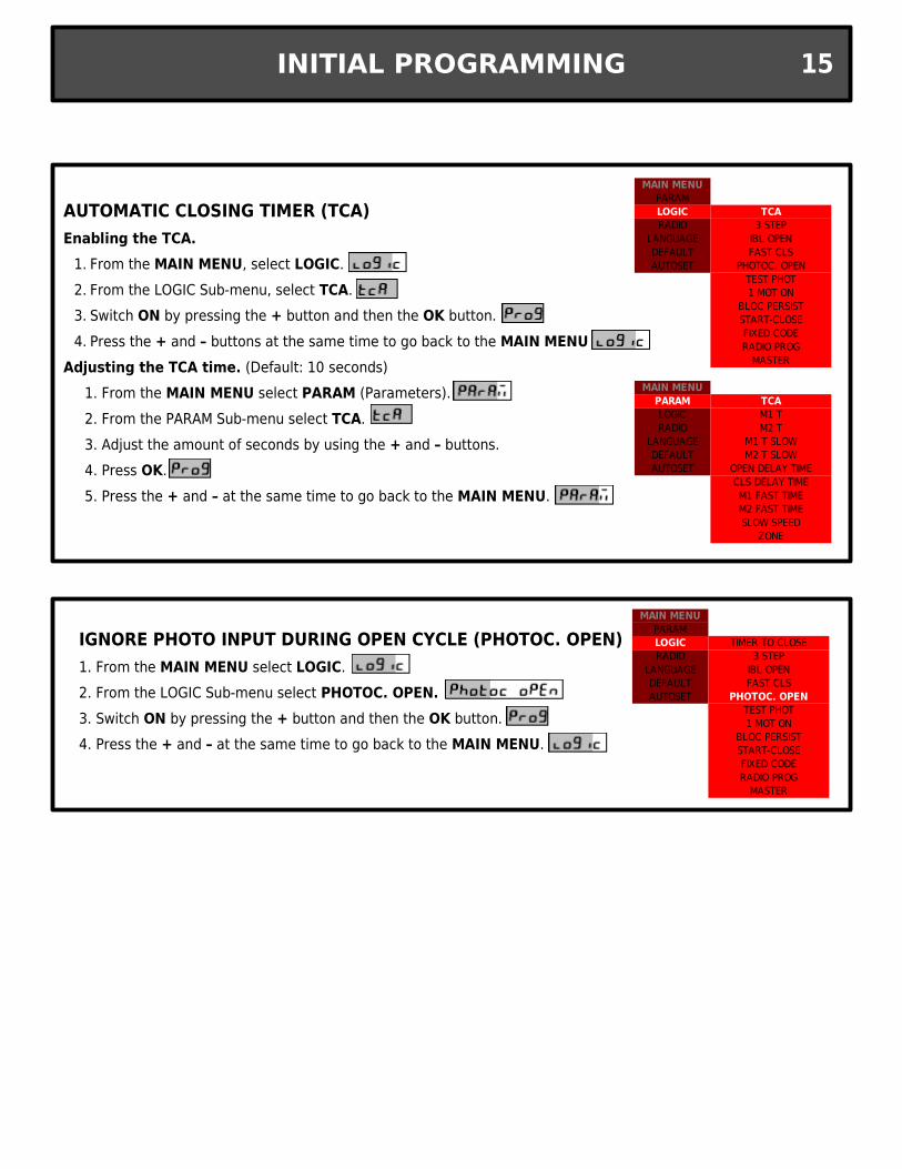
AUTOMATIC CLOSING TIMER (TCA)Enabling the TCA.
1. From the MAIN MENU, select LOGIC.2. From the LOGIC Sub-menu, select TCA.3. Switch ON by pressing the + button and then the OK button.4. Press the + and – buttons at the same time to go back to the MAIN MENU
Adjusting the TCA time. (Default: 10 seconds)1. From the MAIN MENU select PARAM (Parameters).2. From the PARAM Sub-menu select TCA.3. Adjust the amount of seconds by using the + and – buttons.4. Press OK.5. Press the + and – at the same time to go back to the MAIN MENU.
IGNORE PHOTO INPUT DURING OPEN CYCLE (PHOTOC. OPEN)1. From the MAIN MENU select LOGIC.2. From the LOGIC Sub-menu select PHOTOC. OPEN.3. Switch ON by pressing the + button and then the OK button.4. Press the + and – at the same time to go back to the MAIN MENU.
MAINTENANCE & TROUBLESHOOTING16
TECH SUPPORT U.S. TOLL FREE: 877-995-8155 / INT'L: +1-561-995-8155
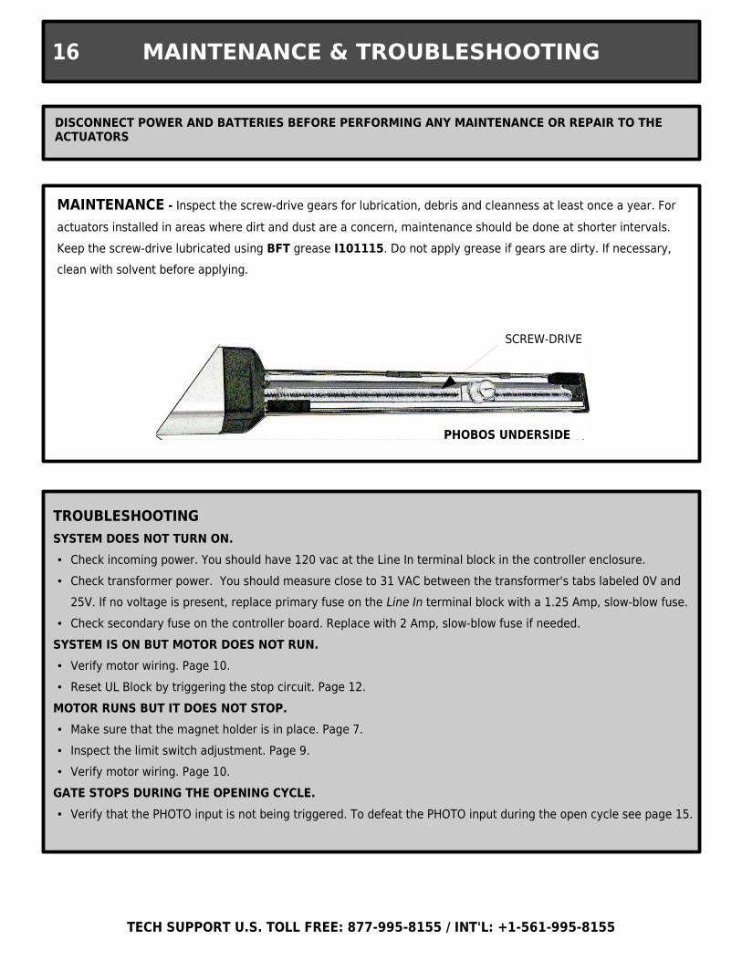
DISCONNECT POWER AND BATTERIES BEFORE PERFORMING ANY MAINTENANCE OR REPAIR TO THE ACTUATORS
MAINTENANCE - Inspect the screw-drive gears for lubrication, debris and cleanness at least once a year. For actuators installed in areas where dirt and dust are a concern, maintenance should be done at shorter intervals. Keep the screw-drive lubricated using BFT grease I101115. Do not apply grease if gears are dirty. If necessary, clean with solvent before applying.
PHOBOS UNDERSIDE
SCREW-DRIVE
TROUBLESHOOTINGSYSTEM DOES NOT TURN ON.● Check incoming power. You should have 120 vac at the Line In terminal block in the controller enclosure.● Check transformer power. You should measure close to 31 VAC between the transformer's tabs labeled 0V and
25V. If no voltage is present, replace primary fuse on the Line In terminal block with a 1.25 Amp, slow-blow fuse.● Check secondary fuse on the controller board. Replace with 2 Amp, slow-blow fuse if needed.
SYSTEM IS ON BUT MOTOR DOES NOT RUN.● Verify motor wiring. Page 10.● Reset UL Block by triggering the stop circuit. Page 12.
MOTOR RUNS BUT IT DOES NOT STOP.● Make sure that the magnet holder is in place. Page 7.● Inspect the limit switch adjustment. Page 9.● Verify motor wiring. Page 10.
GATE STOPS DURING THE OPENING CYCLE.● Verify that the PHOTO input is not being triggered. To defeat the PHOTO input during the open cycle see page 15.
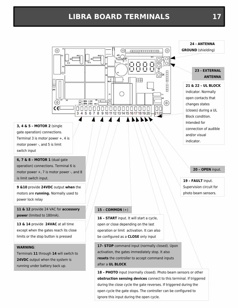
9 &10 provide 24VDC output when the motors are running. Normally used to power lock relay
11 & 12 provide 24 VAC for accessory power (limited to 180mA).
13 & 14 provide 24VAC at all time except when the gates reach its close limits or the stop button is pressed
21 & 22 – UL BLOCK indicator. Normally open contacts that changes states (closes) during a UL Block condition. Intended for connection of audible and/or visual indicator.
15 – COMMON (+)
16 – START input. It will start a cycle, open or close depending on the last operation or limit activation. It can also be configured as a CLOSE only input
17- STOP command input (normally closed). Upon activation, the gates immediately stop. It also resets the controller to accept command inputs after a UL BLOCK
18 – PHOTO input (normally closed). Photo beam sensors or other obstruction sensing devices connect to this terminal. If triggered during the close cycle the gate reverses. If triggered during the open cycle the gate stops. The controller can be configured to ignore this input during the open cycle.
20 – OPEN input.
19 – FAULT input. Supervision circuit for photo beam sensors.
6, 7 & 8 – MOTOR 1 (dual gate operation) connections. Terminal 6 is motor power +, 7 is motor power -, and 8 is limit switch input.
3, 4 & 5 – MOTOR 2 (single gate operation) connections. Terminal 3 is motor power +, 4 is motor power -, and 5 is limit switch input
23 - EXTERNAL ANTENNA
24 - ANTENNA GROUND (shielding)
WARNING: Terminals 11 through 14 will switch to 24VDC output when the system is running under battery back up.
LIBRA BOARD TERMINALS 17
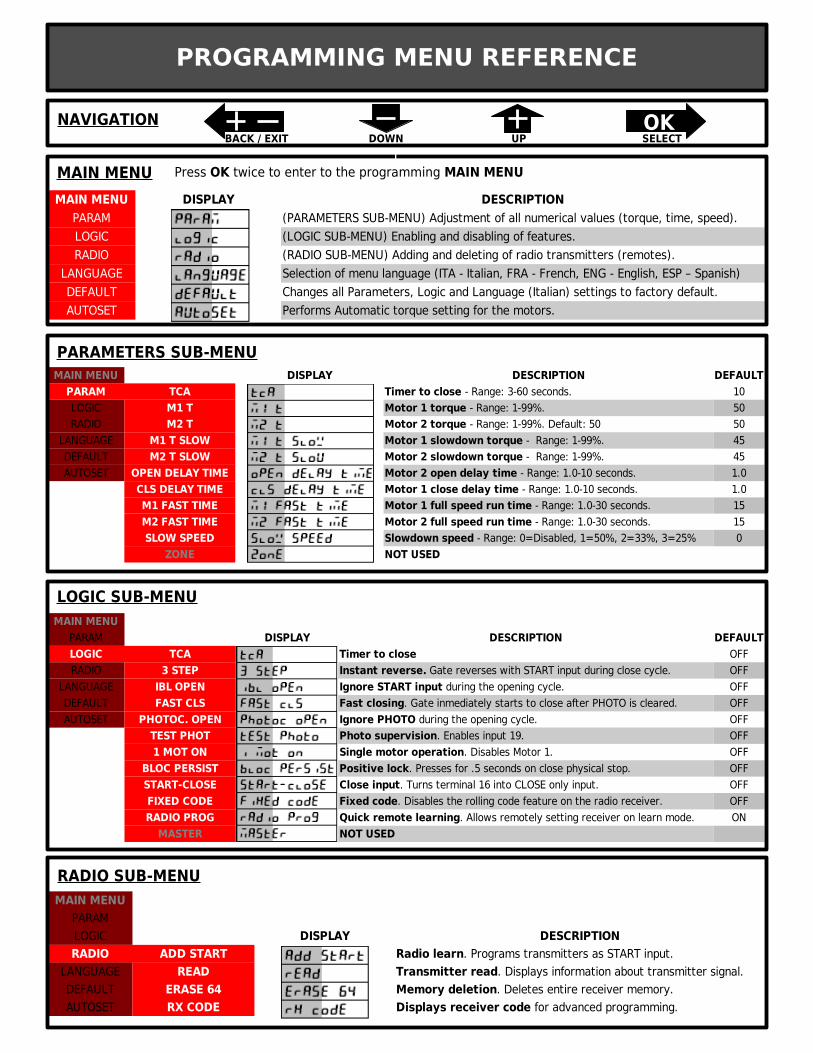
MAIN MENU DISPLAY DESCRIPTIONPARAM (PARAMETERS SUB-MENU) Adjustment of all numerical values (torque, time, speed).LOGIC (LOGIC SUB-MENU) Enabling and disabling of features.RADIO (RADIO SUB-MENU) Adding and deleting of radio transmitters (remotes).
LANGUAGE Selection of menu language (ITA - Italian, FRA - French, ENG - English, ESP – Spanish)DEFAULT Changes all Parameters, Logic and Language (Italian) settings to factory default.AUTOSET Performs Automatic torque setting for the motors.
MAIN MENU DISPLAY DESCRIPTION DEFAULTPARAM TCA 10LOGIC M1 T 50RADIO M2 T 50
LANGUAGE M1 T SLOW 45DEFAULT M2 T SLOW 45AUTOSET OPEN DELAY TIME 1.0
CLS DELAY TIME 1.0M1 FAST TIME 15M2 FAST TIME 15SLOW SPEED 0
ZONE NOT USED
Timer to close - Range: 3-60 seconds.Motor 1 torque - Range: 1-99%.Motor 2 torque - Range: 1-99%. Default: 50Motor 1 slowdown torque - Range: 1-99%.Motor 2 slowdown torque - Range: 1-99%.Motor 2 open delay time - Range: 1.0-10 seconds.Motor 1 close delay time - Range: 1.0-10 seconds.Motor 1 full speed run time - Range: 1.0-30 seconds.Motor 2 full speed run time - Range: 1.0-30 seconds.Slowdown speed - Range: 0=Disabled, 1=50%, 2=33%, 3=25%
MAIN MENU
PARAMETERS SUB-MENU
MAIN MENUPARAM DISPLAY DESCRIPTION DEFAULTLOGIC TCA Timer to close OFFRADIO 3 STEP OFF
LANGUAGE IBL OPEN OFFDEFAULT FAST CLS OFFAUTOSET PHOTOC. OPEN OFF
TEST PHOT OFF1 MOT ON OFF
BLOC PERSIST OFFSTART-CLOSE OFFFIXED CODE OFFRADIO PROG ON
MASTER NOT USED
Instant reverse. Gate reverses with START input during close cycle.Ignore START input during the opening cycle. Fast closing. Gate inmediately starts to close after PHOTO is cleared.Ignore PHOTO during the opening cycle.Photo supervision. Enables input 19.Single motor operation. Disables Motor 1.Positive lock. Presses for .5 seconds on close physical stop.Close input. Turns terminal 16 into CLOSE only input.Fixed code. Disables the rolling code feature on the radio receiver.Quick remote learning. Allows remotely setting receiver on learn mode.
LOGIC SUB-MENU
PROGRAMMING MENU REFERENCE
MAIN MENUPARAMLOGIC DISPLAY DESCRIPTIONRADIO ADD START
LANGUAGE READDEFAULT ERASE 64AUTOSET RX CODE
Radio learn. Programs transmitters as START input.Transmitter read. Displays information about transmitter signal.Memory deletion. Deletes entire receiver memory.Displays receiver code for advanced programming.
RADIO SUB-MENU
NAVIGATION OKBACK / EXIT DOWN UP SELECT
Press OK twice to enter to the programming MAIN MENU