Embed Size (px)
Citation preview
VOL.I0 No. 6, pp. 157-188 'DECEMBER 1948
Philips Technical ReviewDEALING WITH TECHNICAL PROBLEMS
RELATING TO THE PRODUCTS, PROCESSES AND ~STIGATIONS OFTHE PHILIPS INDUSTRIES
by W. PARRISH*) and E. CISNEY*). 548',73: 621.38~.1: 7J8.332
EDITED BY THE RESEARCH LABORATORY OFN.V. PHILIPS' GLOEJLAMPENFABRIEKEN, EINDHOVEN, NETHERLANDS.
AN IMPROVED X-RAY DIFFRACTION CAMERA
For obtaining high quality X-ray diffraction patterns with minimum exposure times,an improved Debye-Scherrer camera has been designed and is produced by NorthAmerican Philips Co.,Inc. Various factors entering the design of the camera and interrelatedin their influence on the properties of the patterns are considered in this article. Thenecessary compromises between such properties as line intensity, line sharpness (reso-lution), contrast and line shape are favorably affected by several resources. Line intensityis improved without loss of resolution by using a rectangular collimuting aperture for theX-ray beam. Contrast is enhanced by surrounding the primary beam on its path to andfrom the specimen by a collimator and exit tube, thus diminishing the film blackeningresulting from radiation scattered in the air. It is shown that these "anti-air-scattertubes" must have definite dimensions in order to insure the limitation of air scatter to aminimum ~thout causing undesirable blind areas in the diffraction patterns and avoid-ing any scattering from the tubes themselves. The optimum forms of the tubes fordifferent purposes have been computed, and the cameras can be provided with one ofseveral systems designed in accordance with the results of these computations. Thetubes are made easily interchangeable. Handling of the cameras in general is simplifiedto a considerable extent by the application of certain mechanical design principles out-lined by Buerger. '
In this article a description is given of animproved camera for the photographic recording ofX-ray diffraction patterns of polycrystalline (e.g.powder) specimens according, to the Deb y e-Scherrer method. There is no need to enumeratehere the many purposes which these patterns mayserve. It is sufficient to state that they aré usedextensively in research and industrial Iaboratoriesfor the identifieation or chemical -analysis ofmaterials, for the examination of crystalline struc-ture and grain size, and for the analysis of stresses,texture etc. 1).Fig. 1 illustrates the well-known principle of the
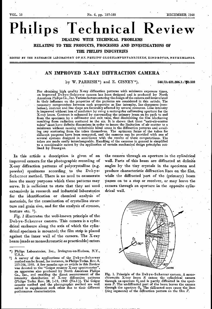
Debye-Scherrer camera. "I'his camera is a cylin-,drical enclosure along the axis of which the cylin-drical.specimen is mounted; the film strip is placedagainst the inner wall of the camera. The X-raybeam (made as monochromatië as practicable) enters
*) Philips Laboratories, Inc., Irvington-on-Hudson, N.Y.,U.S.A.
1) A survey of the applications of the Debye-Scherrermethod canbe found, for instance, in Philips Techn. Rev. 5,157-166,1940. A few months ago an article in this Reviewwas devoted to the "Geiger counter X-ray spectromcter",an apparatus also produced by North American PhilipsCo., Inc., and enabling the direct measurement of theintensity distribution of X-ray diffraction patterns(Philips Techn Rev. 10, 1-12, 1948 (No.I». The Geigercounter method and the photographic method are wellsuited to supplement each other due to their differentperformance characteristics.
the camera through an aperture in the cylindricalwall. Parts of- this beam are diffracted at definit~angles by the tiny crystals in the specimen andproduce characteristic diffraction lines on the film,while the diffracted 'part of the (primary) beampasses on to a stop or receiver, or may leave thecamera through an aperture in the opposite cylin-drical wall.
Fig. 1. Principle of the Debye-Scherrer camera. A mono-chromatic X-ray beam R enters the cylindrical camerathrough an aperture Ol and is partly diffracted in the sped-men P. The undiffracted part of the beam leaves the camerathrough the aperture O2, The diffracted rays cause the lines(ring segments) of the diffraction pattern on the film F.

158 PHILIPS TECHNICAL REVIEW VOL. 10, No. 6
A weU designed Debye-Scherrer camerashould meet the requirements that, on the' onehand, the recording of a pattern be made as easyand quick as possible, while, on the other hand, thehighest possible quality of the resulting patternsbe secured.
As far as ease of handling is concerned, thecameras produced by North American Philips Co.,Inc., have been designed in the main in accordancewith the cameras described a few years ago by M. J.Buerger 2). The principles outlined by Buerger
Fig. 2. The Debye-Scherrer cameras with diameters of57.3 and 114.6 mm, as manufactured by North AmericanPhilips Co., Inc. Next to the cameras are the covers, fittinglight-tight on the cameras, so that it is not-necessary to makeexposures in a dark room nor to cover the film with blackpaper. In each of these cameras the primary X-ray beampasses through two conical tubes between which tbe very thinrod-shaped specimen is mounted. After placing the specimenroughly on the axis of the camera it is accurately centered bymeans of a threaded "pusher" perpendicular to the axis. This isfacilitated by slipping a small magnifying glass on the end ofthe exit tube. During the exposure the glass is replaced by acap containing a small fluorescent screen, on which the pri-mary beam and the shadow of the specimen may be observed.Thus the alignment of the camera and the centering of thespecimen are checked. The fluorescent screen is covered at theinside with black paper, making the camera light-tight, andat the outside with lead glass, absorbing the remainder of theprimary beam without obstructing the view of the fluorescentscreen. The film is placed in the camera according to theStraumanis method: the film takes up nearly 360°, andtwo holes of normalized width of 9 mm are punched in itwhere the tubes are to be inserted. Careful design and machiningof the tubes make it possible to remove them easily formounting the film and to replace them in exactly the correctalignment. The film is -expanded tightly against the innerwall of the camera by means of a movable finger whichpushes one end of the film, the other end being fixed by a stop.
2) M. J. Buerger, The design of X-ray powder cameras,J. Appl. Phys. 16, 501-510, 1945. Cf. also: M. J. Buerger,An X-ray powder camera, Amer. Mineralogist 21, 11-17,1936.
were aimed, among other things, at facilitating thealignment of the camera with the X -ray tube, therecovering of the alignment after temporary remov-al of the camera from its position, the centeringof the specimen in the camera, the rapid mountingof the film, etc. The successful realization of suchprinciples depends mainly on precise mechanicalconstruction. Those are not the subjects which areextensively treated in this article, although somedetails relating to the aforementioned principlesare given in figs 2 and 3 and explained in theaccompanying legends. On the contrary, this articledeals much more thoroughly with the spe edof recording and the quality of the p a t t er n sobtained.
Properties involved in quality of pattern
Information about the nature of the X-rayedspecimen can be deduced from the positions (i.e.,the diffraction angles) of the diffraction lines, fromtheir relative intensities and from the line shape.High quality patterns, therefore, will exhibit thefollowing properties:1) Recording of all lines that are of importance.
This especially refers to very we ak lines,which may often be important in quantitativechemical analysis by X-ray diffraction, and tolines at very small or very large diffractionangles (28 near 'zero or 180°, 8 = Braggangle).
2) Great sharpness of lines. This will enable thediffraction angles to be determined very accu-rately and at the same time it wil] provide a,good resolution of adjacent lines.
3) Good contrast of recorded picture, i.e., mini-mum and relatively uniform background densityon the film in comparison to the density of thelines. A strong background would not onlyaffect the observable recording of very weaklines mentioned in (1), but also impair the mea-surement of the correct relative intensities, forstrong as weU as for weak lines.
4) Good Iine shape, i.e., correct contour, uniformdensity, and constant intensity along theusable length of each line (insofar as the desireddata do not actually depend on broadening,spottiness or specific intensity distribution ofeach line). This property is important for gooddefinition of the position of the lines and forcorrect intensity measurements.
In order to meet the requirement of quickrecording of patterns, especially in view ofpoint (1), we must add to this list of desiderata:
5) High intensity of diffracted rays.
DECEMBER 1948 AN IMPROVED X-RAY DIFFRACTION CAMERA 159
Camera design considerations relating to quality ofpattern and speed of recording
When considering the design factors whichinfluence the abovemerrtioned properties it becomesapparent that in several instances the requirementsare conflicting. For the sake of convenience let usstart from the sharpness of lines.
Sharp definition of the lines mainly depends onthe diameter of the camera, the width and diver-gence of the primary X-ray beam, and the thick-ness of the specimen.Simple geometrical considerations show that the
lines become sharper (i.e. narrower in relation totheir mutual separation distances) with an increase
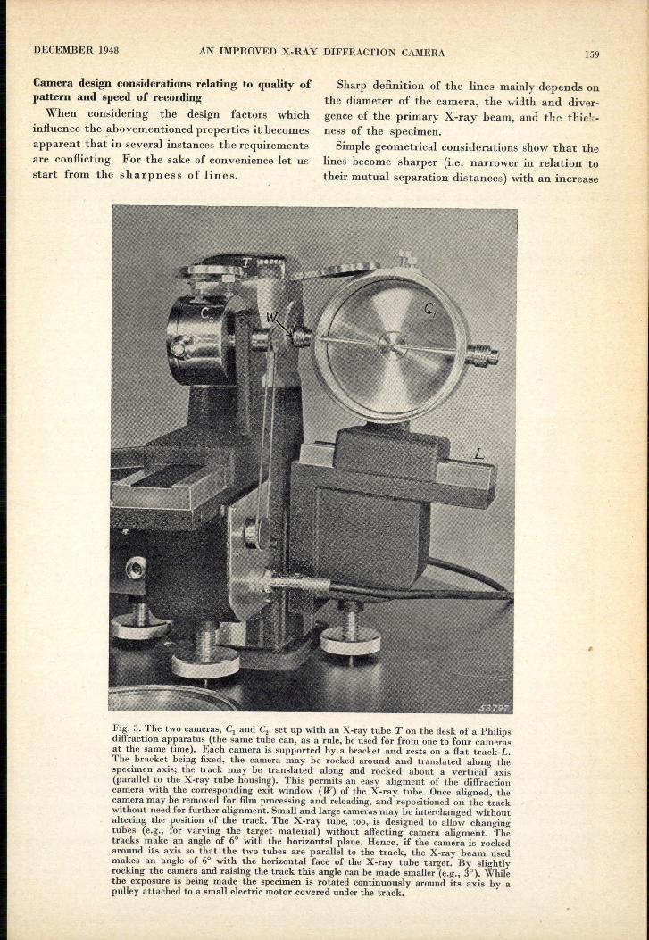
Fig. 3. The two cameras, Cl and Cz, set up with an X-ray tube T on the desk of a Philipsdiffraction apparatus (the same tube can, as a rule, be used for from one to four camerasat the same time). Each camera is supported by a bracket and rests on a flat track L.The bracket being fixed, the camera may be rocked around and translated along thespecimen axis; the track may be translated along and rocked about a vertical axis(parallel to the X-ray tube housing). This permits an easy aligment of the diffractioncamera with the corresponding exit window (W) of the X-ray tube. Once aligned, thecamera may be removed for film processing and reloading,and repositioned on the trackwithout need for further alignment. Small and large camerasmay be interchanged withoutaltering the position of the track. The X-ray tube, too, is designed to allow changingtubes (e.g., for varying the target material) without affecting camera aligment. Thetracks make an angle of 6° with the horizontal plane. Hence, if the camera is rockedaround its axis so that the two tubes are parallel to the track, the X-ray beam usedmakes an angle of 6° with the horizontal face of the X-ray tube target. By slightlyrocking the camera and raising the track this angle can be made smaller (e.g., 3°). Whilethe exposure is being made the specimen is rotated continuously around its axis by apulley attached to a small electric motor covered under the track.

160 PHILIPS TECHNICAL REVIEW VOL. 10, No. 6
in the diameter. of the camera. Enlarging thecamera, however, is soon limited by the rapiddecrease in line intensity. In order to keep theexposure times within reasonable limits, one does
- not go any further, as a rule, with the came:.:_atypeunder consideration, than the frequently used.114.59 mm diameter. The Philips cameras possessdiameters of 114.59 and 57.3 mm 3).
Next, consider the divergence of the irradiatingX-ray beam. Lines will he sharper' for a smallerbeam divergence, as may. be seen from fig. 4. Onthe other hand, a larger area of the X-ray tubefocus contributing to the irradiating energy corres- .ponds with a greater divergence of the beam (thedistance between focus and specimen, and theangle at which the anode surface is viewed beinggiven). Hence, a compromise between line sharp-ness and line intensity. again will be necessary.
A ~ -
~a F~,',~ ., ," ,"/26, .
~~rf::__1...._ -.--.__ :
I,:
54079/. \
Fig. 4. Vertical cross-section of the cylindrical camera (notdrawn to scale), showing film F, specimen P, anode A, focalspot D and beam collimating apertures 81 and 82, The diver-gence of the primary X-ray beam R (in this case limited byaperture S1 and specimen diameter) is a. The same angular .divergence appears between rays diffracted at the outermostpoints of the specimen cross-section and contributing to one .diffraction line (201 = diffraction jmgle). .
Finally the thickness of the specimen (which also~etermines the p.ecessary width of the primarybeam) should be considered. To obtain sufficientlysharp lines, -the specimen must be extremely thin,in some instances 0.3 mm or even less. Evidentlythe X-ray energy diffracted by the specimen will,then, be very small.' So we have once again theconflict between line sharpness and line intensity.In this case, however, other requirements men-tioned above are involved i~ the conflict too.Diminishing the specimen diameter is apt to createa very unfavorable condition with respect to thecontrast of the pattern and the line shape.This may be seen in -the following way:
3) These seemingly odd diameter values have the advantagethat the diffraction angles 2<9are in a simple way numer-ically related to the line distances measured in mm on thefilm: 1° of 20 corresponds to 1 mm with the 114.59 mmcamera, to t!2 mm with the 57.3 mm camera•
. .
The main cause of the occurrence-of a uniformbackground on the film, detrimental to contrast,is the scattering of the primary }(eam in the airthrough which it passes on its way through thecamera 4). Given a certain path length of the beamin air and assuming the beam width in all casesto be equal to the thickness of the specimen, theair volume contributing to the undesired scatteringwill decrease prop ortiona tely to this thickness.The volume of the specimen contributing to thedesired diffraction, however, decreases accordingto the square of the specimen thickness, so thatthe air scatter will he relatively more pronouncedthe thinner the specimen.Similarly, the unfavorable effect on the line shape'
may be understood. Given the average size of thecrystals oriented at random in the specimen, thenumber of crystals irradiated decreases with thesquare of the specimen 'thickness, and so does theaverage number' of spots from which each diffrac- -tion line is built up, while the line width on whichthe spots are distributed diminishes' only propor-tionately to this thickness. Thus, the lines in thediffraction pattern will be less uniformly blackenedand, in the extreme case, tend. to get a spottyappearance on decreasing the specimen diameter .(This. is quite. noticeable· in the examination ofcompounds of low crystal symmetry, for which agiven type of lattice planes will attain an orien-tation suitable for reflecting only ~. a single orvery few positions of the crystal.)The various conflicts pointed out to exist between
desired features and necessitatiI.lg as many com-promises in camera design, may have caused asomewhat gloomy impression as to camera perform-ances which .can be expected. Fortunately, thereare 'several resources which favorably affect thenecessary compromises and which have been appliedin 'the Philips cameras with' considerable success.One such resource, well-known fo; a long time, isthe rotating of the specimen during the exposure(combined with a translation along its axis ifdesired); cf. fig. 3. This results in more crystals.4) We will not consider ill this article causes such as possible
fluorescence (X-rays or light) which is brought about bythe primary beam in the specimen and which is non-directional, or the "white" (non-monochromatic) compo-nents of the X-ray bcam which produce a diffractionspectrum for every wavelength that is present, all thesespectra being superimposed to form a continuous back-ground. These contributions to background (and henceindirectly also the contribution from air scatter) may bediminished by special measures for making the primarybeam more monochromatic, e.g, by means of a "crystalmonochromator" . Such a device mayalso be used withthe Philips cameras. The scattering of the beam at .various apertures through which it passes will be dis-cussed below. .

DECEMBER 1948 AN IMPROVED X-RAY D<IFFRACTION,CAMERA 161
coming+temporarily in an appropriate position forcontributing to a specific diffraction line and, hence,in diminishing the.spottiness of lines. Other resour-ees, also' well-known but, in our case, applied in anovel manner, are concerned with the X-ray beamgeometry and the reduction of air scatter. Thesewill be treated to somewhat greater detail in thefollowing parts of this article.
Geometry of beam eollimating system
The desired beam shape is obtained by means,of a eollimator system, commonly consisting of twopinhole apertures (cf. fig. 4). When' diminishing thespecimen thickness to values of, say, 0.5 or 0.3 mm,the width of the X-ray beam had to be adapted tothe specimen thiekness by making the collimatorapertures narrower. This was necessary, because, allparts of th~ primary beam failing to strik~ thespecimen do not add to the line intensity but onlyto the undesired air scatter. This necessity, how-ever, applies only to the- width of the beam in the"equatorial" cross-section of the camera and thespecimen, represented in fig. 4. The width of thebeam in a direction parallel to the specimen axis,need not he limited to the same content. This means,that the beam need not be made rotation-symme-trical but that it can be given an oblong cross-seetion, by taking a rectangular slit ratherthan a circular pinhole as a first eollimator aper-ture; cf. fig. 5. The obvious advantage ofthis is thata relatively long part of the rod-shaped specimenis irradiated, resulting in a higher intensity of thediffraction lines and, at the same time, in a moreuniform blackening of the lines and truer relativeintensities because a larger number of crystallitesare irradiated 5).. A limit to the slit length is set by the fact thatwith too great a divergence of the X-ray beam in a'direction parallel to the specimen axis, the linesharpness and line shape will àgain begin tosuffer. This is explained with reference to fig. 6. Anideal diffraction line is the intersection of the filmwith a eone of rays the apex of whieh lies in thespecimen and the axis of whieh is the direetion of
5) On the use of a rectangular first collimating aperturesee e.g, F. HaHa and H. Mark, Röntgenographische
. Untersuchung von Kristallen, Leipzig 1937, p. 156. Thesuccessful application of this device depends on extremeprecision in the mechanical construction and particularlyin the alignment of the slit with the focus and the speci-men. Special precision techniques' and tools have beendeveloped for this purpose in the case of our cameras. Theslit is punched out of a piece of lead by means of a specialhob, which, when pressed further (without withdrawing),cuts a circle out of the lead. Thus the slit is automaticallycentered :in: a circular lead disc which may then be fixed atits proper place in the collimator tube.
Fig. 5. Horizontal section of the 'primary X-ray beam. Thefirst collimator aperture Sl is made rectangular; S2 is thecircular second aperture; P, the specimen; D, projected focalspot. At P the X-ray beam has an oblong cross-section, (Thecross-sections of D and of the beam at Sl' S2 and P are turned
. in the plane of the drawing and indicated by dotted lines.)
the primary ray. With a diverging primary beameach ray will produce its separate diffraction cone.Each diffraction "line", then, is formed by thesuperposition of a conunuous series of cones withdifferent axes. This results in a broom-shapedbroadening of each line on .either side of the"equator" of the film, and in the case of a stronglydiverging primary beam it also results in a linebroadening at the equator itself. The effect is verynoticeable at very small and large diffraction angleswhere the arcs form complete circles. .
This well-known "slit effect" is not troublesomewitli the aperture dimensions chosen for ourcameras. The first aperture is 0.5 mm wide and 2 mmlong, the second one is circular, with a diameterof, say, 0.5 mm. The resolving power for adjacentlines . proves to be hardly less than that of theusual systems with two circular pinhole aperturesof 0.5 mm diameter, and it is certainly better than
" Ct\)
\ \\ \\ ,\ \\ \I \I I/ ,
/ I1 /
_~ _,,// /1,/---'
Fig. 6. Slit effect on shape of diffraction lines. Diverging raysof the, primary X-ray beam R produce different cones ofdiffracted rays, each having its original ray as an axis. Diffrac-tion lines on the film are obtained by the superposition ofeccentric rings arising from the Intersection of such coneswith the film. Cl and C2 are the rings produced on the (virtu-ally extended) film surface by the rays rt and rg respectively ;E is the "equator" of the film F.
162 PHILIPS TECHNICAL REVIEW VOL. to, No. 6
that of a similar system with 0.75 mm apertures.Compared with the first system, an intensityfactor of 3 is gained, when this collimator systemis completely filled with radiation.
The value of 0.5 mm was chosen for the aperture widthsbecause it was assumed that in general the specimen wouldbe no thicker than 0.5 mm, and also because this value is welladapted to the focal spot dimensions of the Philips X-raytubes supplied for use in the Philips diffraction apparatus.
- A few remarks should be made concerning this latter point.The collimator system must, on the one hand, insure the
beam width and divergence not to exceed the limits set bythe desired resolution. On the other hand, it is desired thatthe radiation of the X-ray tube be used to good efficiency.This evidently will not be the case if the outermost points ofthe specimen circumference cannot "see" the full projectedsizeof the focal spot because rays comingfrom the ends of thefocal spot are cut off by apertures (cf. fig.4). Therefore, wemight say that the focal spot and the collimator system arewell adapted one to the other if the first collimator aperturein fact could be omitted without affecting the beam shape 6).With the Philips X-ray tube mentioned above the focal
spot is 9mm long. At an angle of 3° from the face of the anodethe projected width of the focal spot is 0.5mm; in that case,rays from the entire focal spot pass through the aperturesof sizementioned above to each point of the specimen cross-section, and the full radiation intensity is utilized. At anangle of 6°, however, which is more commonly used in dif-fraction apparatus, the projected width of the focal spot willbe 0.9mm, resulting in the ends of the spot not being used.If the 3° angle is always used the only function of the first
collimator aperture is to collimate the beam ID case an X-raytube having a larger focal spot than that ofthe Philips tubesis to be used.A similar consideration applies to the 2 mm length of
the first aperture: the dimensions of the focal spot of PhilipsX-ray tubes in this direction being on an average only 1.2mm, the collimating action of the first aperture in this direc-tion likewise becomes apparent ouly if other tubes, havingwider focal spots, are used. With the focus width of 1.2 mmmentioned above, the first aperture is not completely filledby the beam and the intensity gain as compared with twocircular 0.5 mm pinholes, therefore, is somewhat smallerthan indicated above (gain factor about 2-21/2),
Anti-air-scatter tubes
The deleterious effect of air scatter on thecontrast of diffraction patterns can be eliminatedby evacuating the camera. This technique, thoughapplied in some cases, is not convenient in instru-ments for routine investigations. An alternativeand much simpler resource consists in confining theprimary beam on its path to and from the specimenwithin two metal tubes (see fig. 2). The entrancetube also contains the collimator system. Filmbackground is reduced because the air path is nowlimited to the distance between the ends of the twotubes.
6) For a set-up without "first" collimator aperture, cf. A.Guinier, Radiocristallographie, Dunod Paris 1945, p. 80.Tbe same principle is applied also in the Geiger counterspectrometer (cf, footnote-j).
As is well known, incorporating the beam collimatingsystem in a tube inside the camera has, moreover, theimportant advantage that the focus-to-specimen distancecan be made smaller, entailing a considerable increase inintensity.
To reduce air scatter to a minimum one wouldprefer to bring the tubes as close as possible to thespecimen. It is obvious, however, that sufficientspace must be allowed around the specimen forthe emission of the rays diffracted by the specimen.The diffraction lines at angles near 00 and 1800
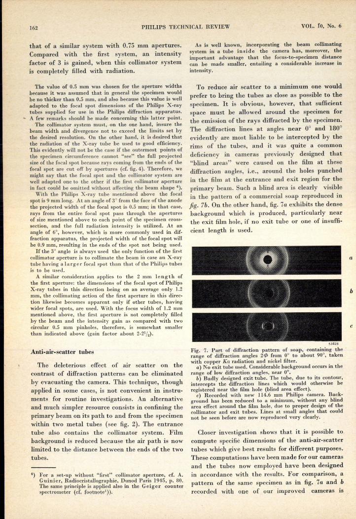
evidently are most liable to be intercepted by therims of the tubes, and it was quite a commondeficiency in cameras previously designed that"blind areas" were caused on the film at thesediffraction angles, i.e., around the holes punchedin the film at the entrance and exit region for theprimary beam. Such a blind area is clearly visiblein the pattern of a commercial soap reproduced infig. 7b. On the other hand, fig. 7a exhibits the densebackground which is produced, particularly nearthe exit film hole, if no exit tube or one of insuffi-cient length is used.
a
b
1 ( ) , c
53825
Fig. 7. Part of diffraction pattern of soap, containing the'range of diffraction angles 2(/1from 0° to about 90°, takenwith copper Ka radiation and nickel filter.
a) No exit tube used. Considerablebackground occursin therange of low diffraction angles, near 0°.
b) Badly designed exit tube. The tube, due to its contour,intercepts the diffraction lines which would otherwise beregistered near the film hole (blind area effect).c) Recorded with new 114.6 mm Philips camera. Back-
ground has been reduced to a minimum, without any blindarea effect around the film hole, due to proper design of thecollimator and exit tubes. Lines at small angles that couldnot be seen before are now reproduced very clearly.
Closer investigation shows that it is possible tocompute specific dimensions of the anti-air-scattertubes which give best results for different purposes.These computations have been made for our camerasand the tubes now employed have been designedin accordance with the results. For comparison, apattern of the same specimen as in fig. 7a and brecorded with one of our improved cameras IS

DECEMBER 1948 AN IMPROVED X-RAY DIFFRACTION CAMERA
I
reproduced in fig. 7c. The occurrence of a "blindarea" outside the film hole is completely avoided;some lines close to the hole, which could not he seenwith previous systems on account of either back-ground or blind area, can now be seen very clearly.The line of thought for the computation of the
tubes will be outlined below.
Computation of optimum form of anti-air-scattertubes
Exit tube
Let us take the exit tube first; see fig. 8. Thediameter of the camera, the diameter of the speci-men and the diameter of the film hole are consideredas being fixed. The primary Xvray beam - provi-sionally assumed to have rotational symmetry -is also considered to be given. The simplest formfor the exit tube to take will he that of a truncatedcone, with the base falling within the film holewhile the width and the position of the tip stillhave to he chosen. -The exit port Will, of course, have to receive the
whole of the' primary beam, whose edge is indi- .cated by line I in fig. 8; The inner rim of the exit
54080Fig. 8. Dimensioning ofthe exit tube. R, diverging X-ray beam;P, specimen;F, film; A, rim of the exit film hole. For the mostfavorable design .the inner rim of the tip of the exit tubemust lie at the point Z. "
port will therefore' have to be outside line I,measured from the axis, or rather outside line I',drawn parallel to I in order to provide a certainclearance t, so 'that the tip of the exit port willnot he touched by the beam (otherwise therewould be considerable scattering from this tip andthe scattered rays would reach' the film witho~thindrance).
On the other hand, we want to introduce therequirement that the abovementioned blind areaeffect should be completely eliminated, i.e., thatthe exi.tport should not obstruct any rays diffracted
163
from the specimen, not even for the lowest usable-diflraction angles. That means that the whole ofthe specimen must be visible from the rim A of the ~film hole. The outer rim, of the exit port will there-fore have to he within line 11, and the inner rimwithin line 11' which has been drawn parallel toline 11 at a distance d equal to the thickness ofthe wall of the tube.The two conditions stated above limit the
allowable position of the inner rim of the exit portto the hatched region between lines l' and 11'.To envelop the primary beam' over the greatestpossible dista~ce it is necessary .to place the innerrim of the exit port in the extreme corner-of thehatched area, i.e., at the point Z where the ,linesI' and I I' intersect.
Collimator tube
Similar considerations lead to the required shapeof the collimator tube, though here the problem is~ore' intricate, as the collimating of the primaryX-ray beam also is involved. We shall provi-sionally adhere to the supposition that the beam . ,is made rotation-symmetrical, thus that both colli-mating apertures are circular, their widths, 251 and252 (which need not be equal}, being determinedin advance on' grounds in part explained above.Also it is assumed that the position of the firstaperture, can be considered fixed on the strengthof certain. geometrical and physical considerations;we have placed it, at a distance à = 20 mm infront of the entrance hole in the film. We are stillfree to choose the position of the second collimatingaperture, of course within certain limits.We can start once again from the fact that the
part of the collimator lying inside the camera maybe shaped as a truncated cone, with the base fallingwithin the hole punched in the film at the spotwhere the beam enters the camera. We shall nowhave to choose the most. suitable ,width and positionof the opening at the strip of the tube. _ .First of all we have to observe that this opening
cannot itself be successfully utilized as a secondcollimating aperture. The primary X-rays are'strongly scattered at the edges of the beam-limit-ing' apertures. If the second beam-limiting aper-ture were to he located at the end of the collimatortube this scattered radiation would reach thefilm unhindered and that result would he worsethan the air scatter it is desired to eliminate. Theseco~d collimating .aperture must, therefore, beplaced inside the collimator tube, and the tube'tip (scatter cup), in addition to its function ofdiminishing air scatter, must keep the rays scattered
",

164 PHILIPS TECHNICAL REVIEW VOL.'lO, No. 6
,. by the aperture away from the film 7). Thus wearrive at the configuration sketched qualita~ivelyin fig. 9.
Fig. 9. Configuration of collimator and exit tubes Kl "andK2
(qualitatively). The second beam-limiting aperture 82 isinside the collimator tube, so that the rays scattered at thisaperture are kept away from the film F by the tube port M(scatte'r cup). P, specimen, A, anode. (At the end of theexit tube, the three closures mentioned in the description offig. 2 are indicated schematically.) • .
From fig.lO we can now deduce the conditionswhich have to be fulfilled by the collimator tube.
The tube tip must not cut off any part of thedivergent beam formed by the apertures 81 and 82(for if it did it would itself act as a second aperture).Hence the condition: 1) The inner rim of the scattercup must be outside line I, measured from the axis,or rather outside line I' drawn parallel to I, againto allow for the necessary clearance t.
Furthermore, the scatter .cup must intercept allscattered rays which, coming from the oircum-ference of 82, ~ould fall outside the film hole onthe opposite side of the camera (point A). Conse-.quently: 2) The inner rim of the scatter cup mustlie inside line Ill. The two conditions taken to-gether indicate that the inner rim of the scattercup must lie in the hatched region shown in fig. 10.
Finally, any blind area in the 1800 region outsidethe entrance film hole must be avoided, whichmeans that it must be possible to see the whole ofthe specimen unhindered from the rim C of thefilm hole. Hence it follows that the outer rim of thescatter cup must lie on the inside öf line IV, or,if we draw a line IV' parallel" to TV at a distanceequal to the wall thickness of the tube: 3) Theinner rim of the scatter cup must be on the insideof line IV'.) J
We see that all three conditions together stillleave us" free to place the rim of the scatter cupsomewhere in the trianguiar part of the hatched.field delineated by heavy lines. To envelop the7) It is a common fault in many camera designs that this
requirement is not met. The importance of the require-ment was pointed out by M. J. Bu erg er, l.c. (1945),p. 505. '
primary beam over the greatest possible length,the rim of the scatter cup will have to be placed inthe farthermost right-hand corner (W') of thetriangle. .
The position and the width of the collimatortube tip are thus fixed as soon as the position ofthe second collimating aperture 82, as yet unspeci-fied, has been established. When we vary thisposition we see that the more nearly horizontalline I (and 1') becomes, and thus the smaller thedivergence of the X-ray beam, the closer the pointW' is brought to the specimen. It is thereforedesirable to place the aperture 82 as close to thespecimen as possible. A limit to this is set because,as a closer examination will show, as 82 is broughtnearer to the specimen the apex (W) of thehatched area is shifted in the same direction. 82
can only be shifted, therefore, until point Whas r e a ch ed-t he line IV', the delineated tri-angle in this case being reduced to that single point.The position of the second collimating aperture isthen unambiguously established and the largestpossible length of the collimator tube correspondsto this situation.
At· the same time this position of the secondaperture is also the most suitable for the design ofthe exit tube. In. our· discussion on this pointwith reference to fig. 8, which led to the tip of thist~be being placed at point Z, we had assumed the 'primary beam to be limited by line I as given. It isapparent that point Z, too, now comes closer tothe specimen the more nearly horizontal line I ismade. The permissible lengths of both the colli-mator tube and the exit tube thus become a maxi-mum when the position of 82 is determined bythe, foregoing ·considerations 8).
• 54082Fig. 10. Dimensioning of the collimator tube. R, X-ray beam;P, specimen; 81 and 82, apertures; F, film; C and A, rims of theentrance and exit film holes. With the position of 82 being
. chosen arbitrarily as yet, for best results the inner rim of thecollimator tube port must lie at the corner W'of the delineatedtriangle. .
8) Incidentally, it should be pointed out that care must betaken to prevent rays scattered back from the wall insidethe exit tube from returning through the tube tip andreaching the film. This requirement can easily b!l met bymaking thl~ Wp.~ çQlljçal or by step-drilling it.

DECEMBER 1948. AN,IMPROVED X-RAY DIFFRACTION CAMERA 165
The optimum dimensi~ns of the anti-air-scatter tubes cannow be computed in an elementary, though not very simplemanner, from the criteria established above. We introduce asystem of coordinates ç, 1], having its origin 0 at the centerof the entrance film hole as indicated in fig. 11. There are fiveunknowns: u, the ç-coordinate defining the position of thesecond collimating aperture 82; v and w, coordinates of pointW, indicating the position and half the width of the collima-tor tube tip; x and y, coordinates of point Z, indicating theposition and half the width of the exit tube tip.According to elementary principles of analytic geometry
we can write the equation for each of the straight lines I'-IV'in the form '
1/-171 1/-1/2Ç-Ç1 = Ç-Ç2'
where Ç1' 1/1and Ç2' 1/2are the, coordinates of two fixed pointsthrough which the line is drawn. Since, according to theabove, point W must be situated simultaneouslyon 'thelines 1', III and IV', we get for the three unknowns u, v, w,the three equations:
w+ (Sl-t) w- (52+ t)1': v+ a, v-u
HI:w + S2 w-fv-u = v-2R'
IV': w + (r + d) = w - (f - d)v-R v
'I
y.+ (r + d), y - (f - d)x-R x-2R
Elimination of u and v'from the first three of these equa-tions yields a rather cumbersome quadratic equation for w.After w is known, v and u may readily he computed, andlikewise x and y with the help of u. We need not give here,the detailed solutions and the computation of the numericalvalues.
H':
Different types of anti-air-scatter tubesIn the above the' rigorous requirement was set
that nothing must be lost from the diffractionpattern, that is to say, the whole of thé specimenmust be visible from the rims of :the film holes.In practice, however, -this will never be requiredfor the 0° section and the 180° section of the patternat the same time. Organic compounds which oftenpossess large interplanar spacings and, thereby, willproduce very low angle diffraction lines, in generalwill not yield any "back-reflection" lines (near180°). Conversely, inorganic compounds ordinarilygive distinct back-reflection lines hut rarely showlines corresponding to large spacings.
"..1
54-084-
Fig. 11. The position of the second aperture 82, and that of the points Wand Z, indi-cating the best locution and width of the tips of the two tubes, are given in the 1;, 1/-coordinate system by the cd'ordinates u; v, W; x, y, respectively. The coordinates of allpoints used for the equations of lines I', -II', III and IV' are indicated in the diagram.
"
Here' R is the radius' of the camera, r the radius of thespecimen, d the wall thickness of the tube, t the desiredclearance between the primary beam and the inner rim of thetube tip, f the radius of the entrance and exit hole punchedin the film, 52 half the width of the second collimating aper-ture; crand SI indicate the position and half the width of thefirst collimating aperture 9). All these symbols stand forknown "numerical _values. ' .Since'point Z lies on the lines I' and II' we derive for the
unknowns x and y the equations:
I':
9) These and the following equations contain two veryobvious simplifications (cf. fig. 11): the circular cross-section of the specimen to which linesH and IV should betangent was replaced by its vertical diameter; and therim of the two holes in the curved film was assumed tohave l;-coordinates zero and 2R, respectively. Actualcomputations showed that the latter simplification ispermissible even in the case of the small camera (2R =57.3 mm) in which the film curvature is greatest.
Thus three different cases may be distinguishedas regards the desired angle region of the diffractionpatter~:' the examination of - forward diffractiononly, of back-reflection only, and general wo~kwhere neither very large nor very .~mall angles areof interest but an optimal record of the entire"normal" angle region is desired. We have deve-loped a number of different anti-air-scatter tubesystems for these various purposes. Some of theseare described below, the indica~ed figures corre~-ponding to the. 114.6 mm camera.
The first tube system (No.77) is calculated forforward diffraction work. The rigorous blind areacondition has been applied to the exit tube. Fullline intensity is' obtained at angles > 4.5° [theminimum angle permitted by the film hole). Linesat angles larger than 90° need not be recorded in

166 PHILIPS TECHNICAL 'REVIEW, VOL. 10, No. 6
this case. The collimator tube, therefore, has beenextended so as nearly to touch the specimen. Thishas reduced the non-enveloped length of the primaryX-ray beam to 19.9 mm. /An analogous tube system (No.85) is made for
back-reflection work. In this case only the colli-mator tube is subjected to the rigorous blind areacondition, providing full line intensity up toangles of 175.5°. This tube system is used, e.g., forthe precision determination of lattice constants.The non-enveloped beam length is 28.8 mm.
For the third case, i.e., all general work as innormal identification of compounds etc., the rigor-ous blind. area condition has been replaced by aless rigorous one for both the collimator and theexit tube. This less rigorous condition consists insetting the requitement that, though not the entirespecimen cross-section, at least part of it should bevisible from the rim of the film holes. This meansthat a gradual intensity drop (a kind of "half-shadow") of the outermost lines towards the holesis allowed. Pig. 12 illustrates the gain, in tube length
54083
Fig. 12. For the strict requirement made above, viz., thatthe exit tube tip must not cause any obscuration of thespecimen for points outside the film hole (rim A), in mostpractical cases the less strict requirement can be substitutedthat there should be no complete obscuration while apartial one could be tolerated. The former border line (Il')
, dotted in.this diagram may then he replaced bythe full line IJ'.The intersection point (Z) will come closer to the specimen,at Z. The exit tube may, therefore, be longer. Similar consi-derations apply to the collimator tube.
obtainable by' substituting this less rigorous condi~tion for the rigorous one. Accordingly, the non-enveloped primary beam path with the third systemof tubes (No. SS) has been reduced to 10.9 mm!The air scatter is extraordinarily weak, with thistube system. The intensity drop of the diffractionlines as they approach the film holes is noticeableat angles' smaller than 6° and greater than 172.5°.For cases where high intensity is of prime impor-
tance, and a smaller resolution and stronger back-ground are permissible, a similar' tube' systemhaving a wider second collimating aperture hasbeen designed (0.9 mm; No.73). The non-envelopedbeam length is 30.2 mm for these tubes.
The same five equations as used above hold for the compu-tation of the tubes with the less rigorous blind area condition,the only difference being that +r has to be replaced by -r,as may easily be seen from fig. 12.'In the computation of collimator ánd exit tubes outlined
above it was assumed that the X-ray beam has a. circularcross-section. Its real shape, however, is oblong (fig. 5). Inorder to take in this oblong cross-section, a slit-shaped exitport evidently would be best suited. Nevertheless, for prac-tical reasons the exit port, as well as the scatter cup, are,made circular in all cases. This means that the exit port inthe equatorial plane of the camera is about 3 times widerthan is requiredfor taking in the whole width of the primarybeam. As a result, in order to prevent the occurrence of ablind region in the equatorial plane, the exit tube tip must berelatively a little farther away from the specimen, and thetube, therefore, has not the full theoretically feasible length.The difference is approximately compensated by the gainin length, obtained by changing from the rigorous to the lessrigorous blind area condition.
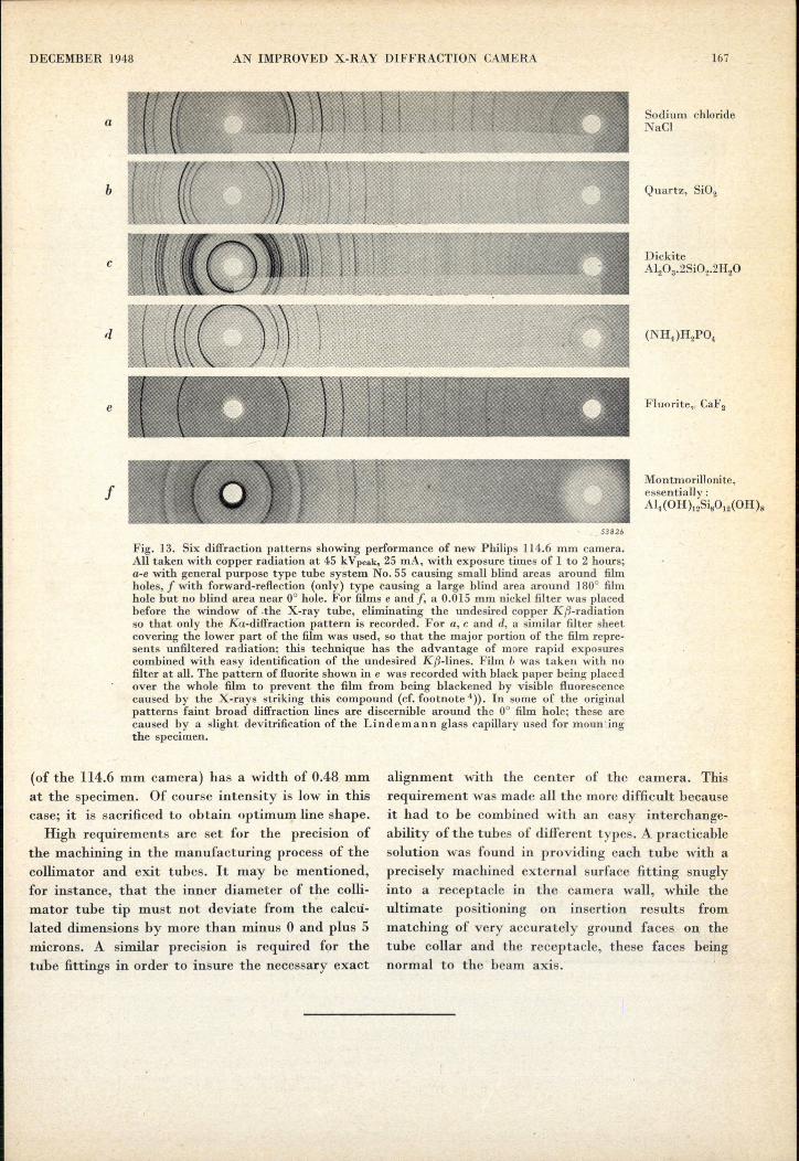
In fig. 13 a number of patterns are reproducedwhich were recorded by the 114.6 mm camera,making use of the general purpose type No. 55(films a-e) or of the forward-reflection type (filmf) of anti-air-scatter tubes. The latter pattern hasno blind area around the 0°film hole, the heavy broaddiffraction ring in this region corresponding to alattice plane spacing of ca. 15A, but has a large blindarea around 180°. (The film of soap, fig. 7c, was alsoobtained with this type of collimator.) In thecase of the former patterns (a-e) .. the very smallpartial blind area around both holes can he seen-''].All the patterns are remarkable for their low back-ground and their sharp and uniformly blacke~edlines. The exposure times for these patterns, takenwith copper radiation at 45 kVpeak, 25 mA, wereno longer than 1 to 2 hours, while a good patternof quartz powder (b) could be obtained even withmuch 'shorter exposures (10 to 15 minutes).
Finally,ït should he mentioned that for studiesdepending on differences in line shape, e.g., for themeasurement .of particle size- by line broadening,or , the examination of preferred orientations ofcrystallites by non-uniform. line blackening, it isdesirable to irradiate the specimen only along anaxial 'length about equal to the diameter of thespecimen. For this purpose collimators of a- moreconventional type having two circular pinholes areprovided: with a first aperture of, e.g., 0.2 mmand' a second one of 0.4 mm diameter, the beam
10) The blind area becomes visible by virtue of ilie fam'tresidual background of the film which is caused mainlyby white radiation diffracted by the specimen.
DECEMBER 1948 AN IMPROVED X-RAY DIFFRACTION CAMERA
a
b
c
e
f
. 53826
Fig. 13. Six diffraction patterns showing performance of new Plrilips 114.6 mm camera.AU taken with copper radiation at 45 kVpeak, 25 mA, with exposure times of 1 to 2 hours;a-e with general purpose type tube system No. 55 causing small blind areas around filmholes, J with forward-reflection (only) type causing a large blind area around 180° filmhole but no blind area near 0° hole. For films e and J, a 0.015 mm nickel filter was placedbefore the window of .the X-ray tube, eliminating the undesired copper Kf1-radiationso that only the Ka-diffraction pattern is recorded. For a, c and cl, a similar filter sheetcovering the lower part of the film was used, so that the major portion of the film repre-sents unfiltered radiation; this technique has the advantage of more rapid exposurescombined with easy identification of the undesired Kf1-lines. Film b was taken with nofilter at all. The pattern of fluorite shown in e was recorded with black paper being placedover the whole film to prevent the film from being blackened by visible fluorescencecaused by the X-rays striking this compound (cf. footnote 4». In some of the originalpatterns faint broad diffraction lines are discernible around the 0° film hole; these arecaused by a slight devitrification of the Lindemann glass capillary used for mountingthe specimen.
(of the 114.6 mm camera) has a width of 0.48 mmat the specimen. Of course intensity is low in thiscase; it is sacrificed to obtain optimum line shape.High requirements are set for the precision of
the machining in the manufacturing process of thecollimator and exit tubes. It may be mentioned,for instance, that the inner diameter of the colli-mator tube tip must not deviate from the calcu-lated dimensions by more than minus 0 and plus 5microns. A similar precision is required for thetube fittings in order to insure the necessary exact
167
Sodium chlorideNaCl
Quartz, Si02
DickiteAI.03·2Si02·2H20
Fluorite, CaF 2
Montmorillonite,essentially:Al4 (OH)12Siij0)2(OH)a
alignment with the center of the camera. Thisrequirement was made all the more difficult becauseit had to be combined with an easy interchange-ability of the tubes of different types. A practicablesolution was found in providing each tube with aprecisely machined external surface fitting snuglyinto a receptacle in the camera wall, while theultimate positioning on insertion results frommatching of very accurately ground faces on thetube collar and the receptacle, these faces beingnormal to the beam axis.
--- ------------------~---------------------------------------------------------------------------------------
168 PHILIPS TECHNICAL REVIEW VOL. 10, No. 6
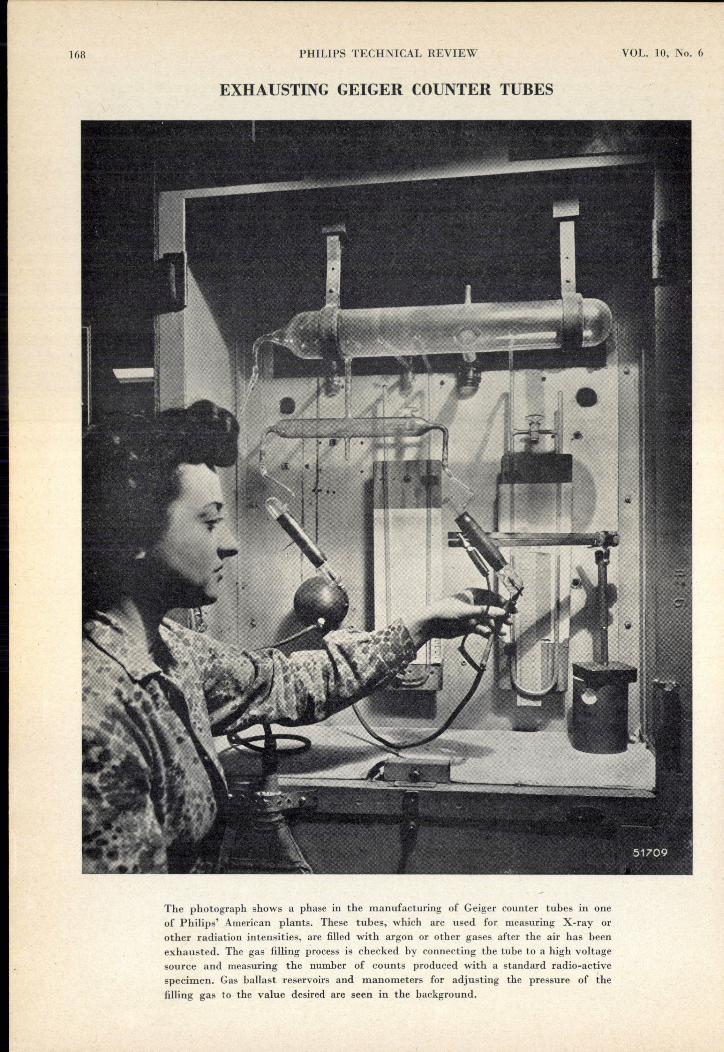
EXHAUSTING GEIGER COUNTER TUBES
The photograph shows a phase in the manufacturing of Geiger counter tubes in oneof Philips' American plants. These tubes, which are used for measuring X-ray orother radiation intensities, are filled with argon or other gases after the air has beenexhausted. The gas filling process is checked by connecting the tube to a high voltagesource and measuring the number of counts produced with a standard radio-activespecimen. Gas ballast reservoirs and manometers for adjusting the pressure of thefilling gas to the value desired are seen in the background.


![Rosetta Langmuir probe performance - DiVA portal680862/FULLTEXT01.pdf1.3.1 Debye shielding and Debye length Debye shielding [1] is an innate ability of the plasma to shield out local](https://img.pdfslide.us/doc/110x75/60ffba69c4d405429359b4af/rosetta-langmuir-probe-performance-diva-680862fulltext01pdf-131-debye-shielding.jpg)