Embed Size (px)
Citation preview
April 11, 2020
Philips Respironics E30 ventilator -device training presentation
Julie Yarascavitch, Sr. Global Clinical Applications Manager
Emergency Use Authorization
The Philips Respironics E30 Ventilator is not FDA cleared or approved. The Philips Respironics E30 Ventilator is provided globally for use under local emergency use authorizations, such as the FDA Emergency Use Authorization for ventilators, Health Canada Interim Order for use in relation to COVID-19, and waiver of CE marking, which authorize its use for the duration of the COVID-19 public health emergency, unless terminated or revoked (after which the products may no longer be used).
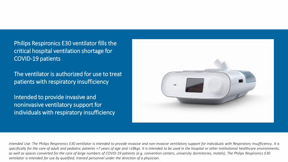
Intended Use: The Philips Respironics E30 ventilator is intended to provide invasive and non-invasive ventilatory support for individuals with Respiratory Insufficiency. It is specifically for the care of adult and pediatric patients >7 years of age and >18kgs. It is intended to be used in the hospital or other institutional healthcare environments, as well as spaces converted for the care of large numbers of COVID-19 patients (e.g. convention centers, university dormitories, motels). The Philips Respironics E30 ventilator is intended for use by qualified, trained personnel under the direction of a physician.
Philips Respironics E30 ventilator fills the critical hospital ventilation shortage for COVID-19 patients
The ventilator is authorized for use to treat patients with respiratory insufficiency
Intended to provide invasive and noninvasive ventilatory support for individuals with respiratory insufficiency
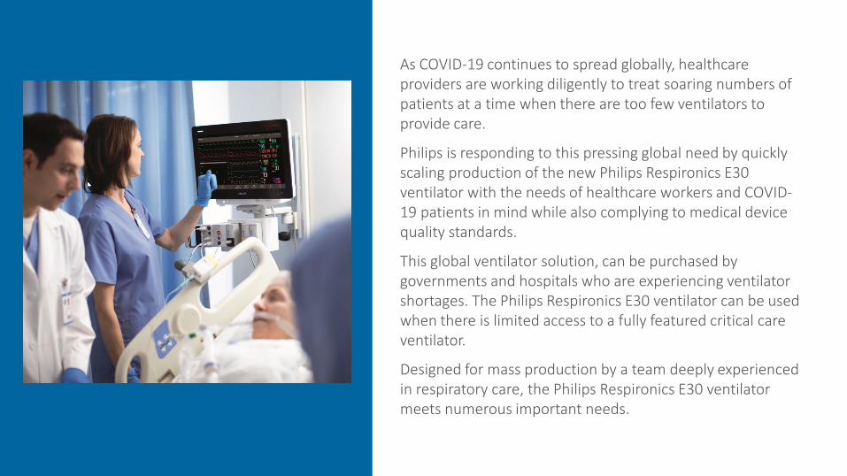
As COVID-19 continues to spread globally, healthcare providers are working diligently to treat soaring numbers of patients at a time when there are too few ventilators to provide care.
Philips is responding to this pressing global need by quickly scaling production of the new Philips Respironics E30 ventilator with the needs of healthcare workers and COVID-19 patients in mind while also complying to medical device quality standards.
This global ventilator solution, can be purchased by governments and hospitals who are experiencing ventilator shortages. The Philips Respironics E30 ventilator can be used when there is limited access to a fully featured critical care ventilator.
Designed for mass production by a team deeply experienced in respiratory care, the Philips Respironics E30 ventilator meets numerous important needs.
5
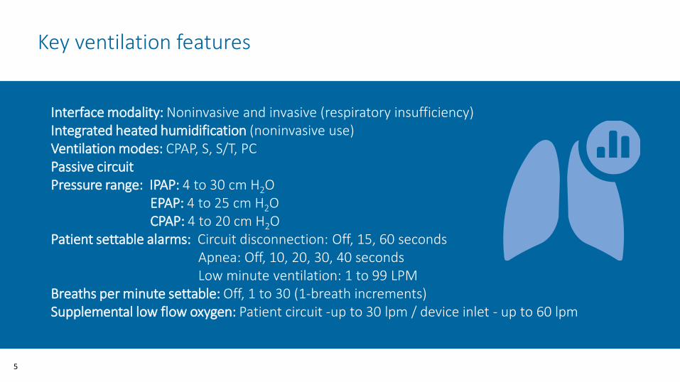
Interface modality: Noninvasive and invasive (respiratory insufficiency)Integrated heated humidification (noninvasive use)Ventilation modes: CPAP, S, S/T, PC Passive circuitPressure range: IPAP: 4 to 30 cm H2O
EPAP: 4 to 25 cm H2OCPAP: 4 to 20 cm H2O
Patient settable alarms: Circuit disconnection: Off, 15, 60 secondsApnea: Off, 10, 20, 30, 40 secondsLow minute ventilation: 1 to 99 LPM
Breaths per minute settable: Off, 1 to 30 (1-breath increments)Supplemental low flow oxygen: Patient circuit -up to 30 lpm / device inlet - up to 60 lpm
Key ventilation features
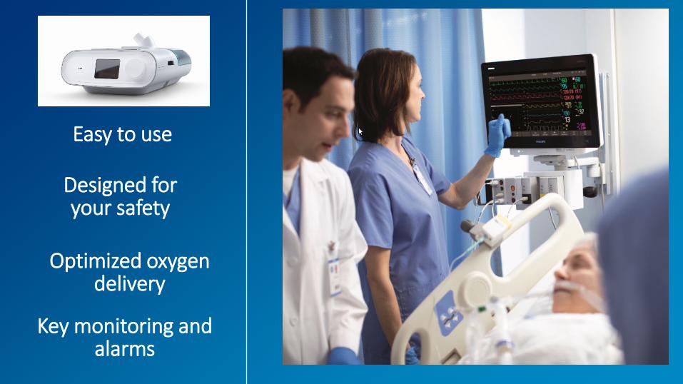
Easy to use Designed for your safety
Optimized oxygen delivery
Key monitoring and alarms

Quick set-up and simple operations allowing healthcare providers with a wide range of skill sets to treat and monitor patients.
Easy to use
Device overview• Device front with humidifier• Removing the humidifier• Device back
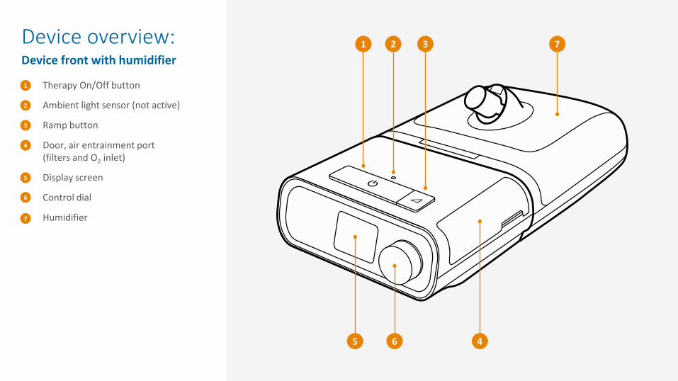
Device overview: Device front with humidifier
Therapy On/Off button
Ambient light sensor (not active)
Ramp button
Door, air entrainment port(filters and O2 inlet)
Display screen
Control dial
Humidifier
1
2
3
4
5
6
1 2 3 7
5 6 4
7
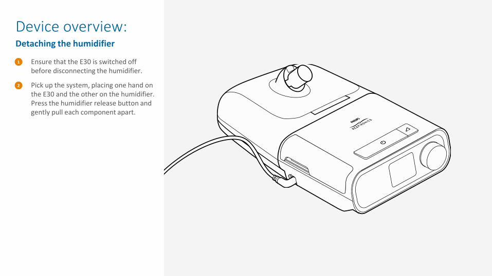
Ensure that the E30 is switched off before disconnecting the humidifier.
Pick up the system, placing one hand on the E30 and the other on the humidifier. Press the humidifier release button and gently pull each component apart.
2
1
Device overview: Detaching the humidifier
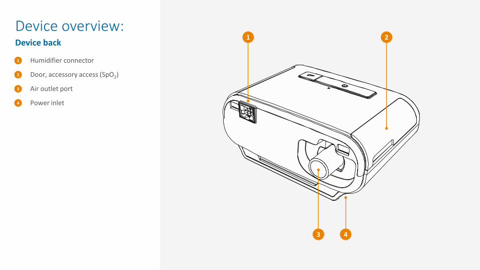
Device overview: Device back
Humidifier connector
Door, accessory access (SpO2)
Air outlet port
Power inlet
1
2
3
4
1 2
3 4

Setting up the device power• Configuration A – External Alarm Module (EAM)• Configuration B – Uninterrupted Power Supply (UPS)
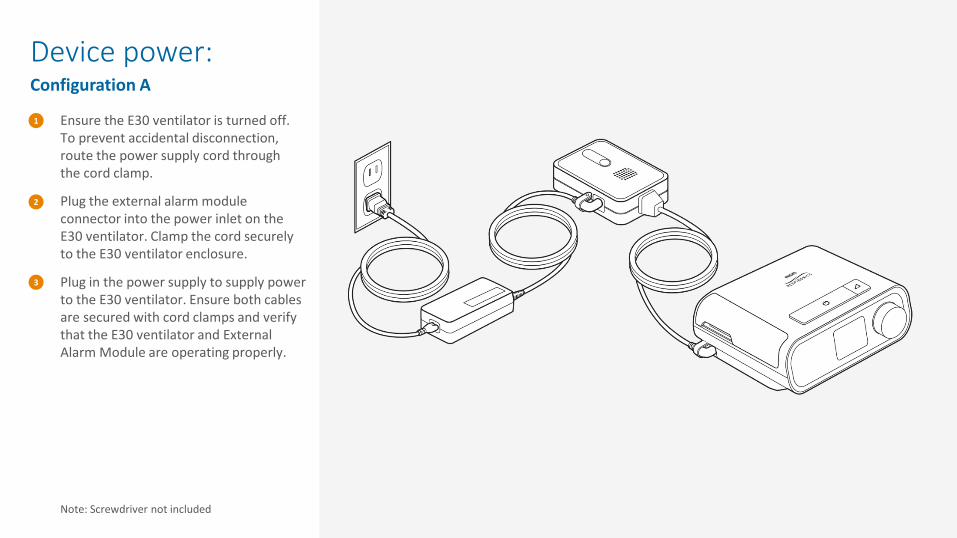
Device power: Configuration A
Ensure the E30 ventilator is turned off. To prevent accidental disconnection, route the power supply cord through the cord clamp.
Plug the external alarm module connector into the power inlet on the E30 ventilator. Clamp the cord securely to the E30 ventilator enclosure.
Plug in the power supply to supply power to the E30 ventilator. Ensure both cables are secured with cord clamps and verify that the E30 ventilator and External Alarm Module are operating properly.
Note: Screwdriver not included
1
2
3
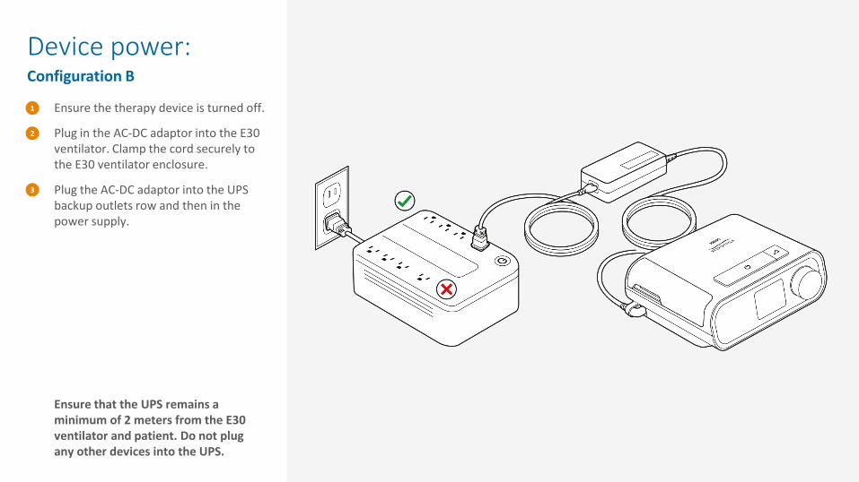
Device power: Configuration B
Ensure the therapy device is turned off.
Plug in the AC-DC adaptor into the E30 ventilator. Clamp the cord securely to the E30 ventilator enclosure.
Plug the AC-DC adaptor into the UPS backup outlets row and then in the power supply.
Ensure that the UPS remains a minimum of 2 meters from the E30 ventilator and patient. Do not plug any other devices into the UPS.
1
2
3

Navigating the menu• Adjusting therapy settings
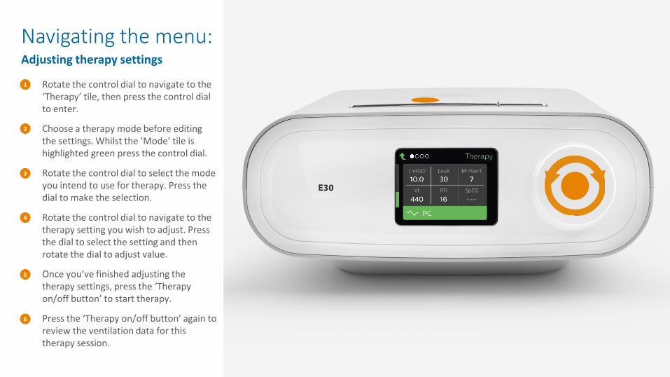
Rotate the control dial to navigate to the ‘Therapy’ tile, then press the control dial to enter.
Choose a therapy mode before editing the settings. Whilst the ’Mode’ tile is highlighted green press the control dial.
Rotate the control dial to select the mode you intend to use for therapy. Press the dial to make the selection.
Rotate the control dial to navigate to the therapy setting you wish to adjust. Press the dial to select the setting and then rotate the dial to adjust value.
Once you’ve finished adjusting the therapy settings, press the ‘Therapy on/off button’ to start therapy.
Press the ‘Therapy on/off button’ again to review the ventilation data for this therapy session.
6
5
4
3
2
1
Navigating the menu: Adjusting therapy settings

Recommended circuit set-ups contain a bacterial/viral filter to minimize exposure for healthcare providers when used invasively or noninvasively with example accessories that may be used, such as a full-face, non-vented (without integrated leak) mask, or helmet.
Designed for your safety
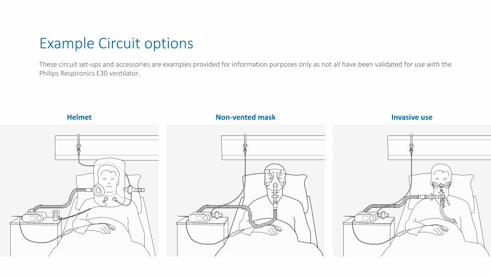
Example Circuit optionsThese circuit set-ups and accessories are examples provided for information purposes only as not all have been validated for use with the Philips Respironics E30 ventilator.
Helmet Non-vented mask Invasive use
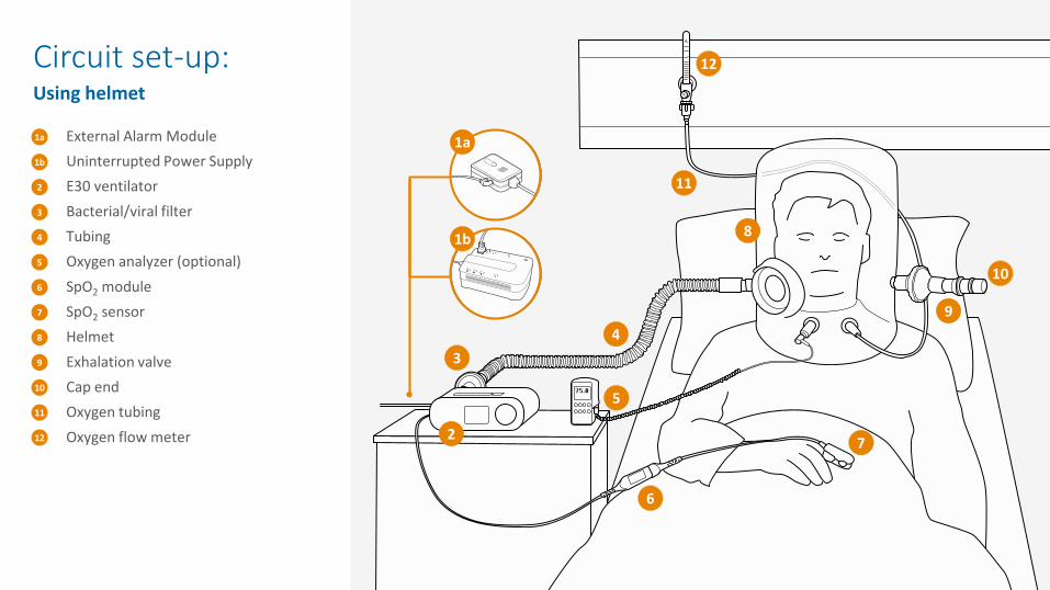
External Alarm Module Uninterrupted Power SupplyE30 ventilatorBacterial/viral filterTubingOxygen analyzer (optional)SpO2 moduleSpO2 sensorHelmetExhalation valveCap endOxygen tubingOxygen flow meter
1a
2
3
4
5
6
2
34
5
6
Circuit set-up: Using helmet
7
8
9
10
11
12 7
8
9
10
11
12
1b
1b
1a
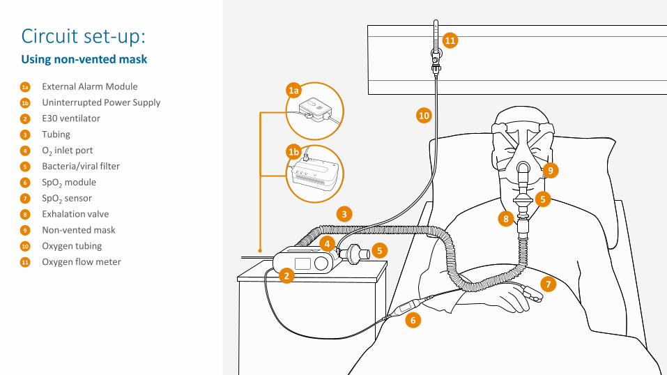
External Alarm Module Uninterrupted Power SupplyE30 ventilatorTubingO2 inlet portBacteria/viral filterSpO2 moduleSpO2 sensorExhalation valveNon-vented maskOxygen tubingOxygen flow meter
1a
2
3
4
5
6
2
3
45
6
Circuit set-up: Using non-vented mask
7
8
9
10
11
7
8
9
10
11
1b
5
1b
1a
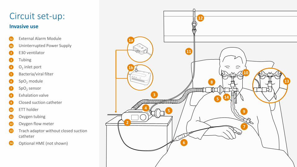
External Alarm Module Uninterrupted Power SupplyE30 ventilatorTubingO2 inlet portBacteria/viral filterSpO2 moduleSpO2 sensorExhalation valveClosed suction catheterETT holderOxygen tubingOxygen flow meterTrach adaptor without closed suction catheterOptional HME (not shown)
1a
2
3
4
5
6
2
3
4 5
6
Circuit set-up: Invasive use
7
8
9
10
11
7
8
9
10
11
12
1b
5 14
12
13
14
1b
1a
13

Safe entrainment of oxygen (device inlet up to 60 lpm / patient circuit up to 30 lpm) to deliver high levels of inspired oxygen.
Optimized oxygen delivery
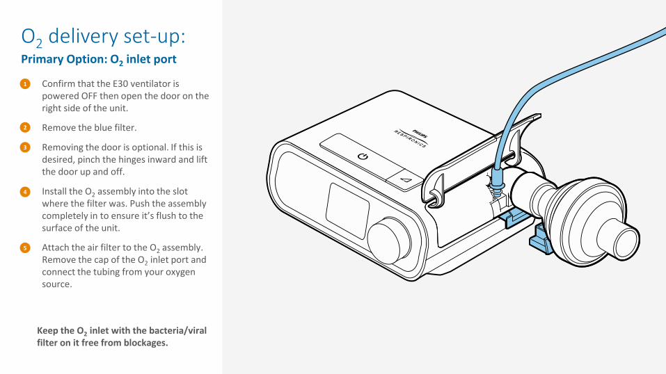
Confirm that the E30 ventilator is powered OFF then open the door on the right side of the unit.
Remove the blue filter.
Removing the door is optional. If this is desired, pinch the hinges inward and lift the door up and off.
Install the O2 assembly into the slot where the filter was. Push the assembly completely in to ensure it’s flush to the surface of the unit.
Attach the air filter to the O2 assembly. Remove the cap of the O2 inlet port and connect the tubing from your oxygen source.
1
2
3
4
5
O2 delivery set-up: Primary Option: O2 inlet port
Keep the O2 inlet with the bacteria/viral filter on it free from blockages.
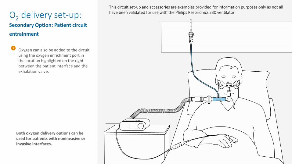
Oxygen can also be added to the circuit using the oxygen enrichment port in the location highlighted on the right between the patient interface and the exhalation valve.
1
O2 delivery set-up: Secondary Option: Patient circuit entrainment
Both oxygen delivery options can be used for patients with noninvasive or invasive interfaces.
This circuit set-up and accessories are examples provided for information purposes only as not all have been validated for use with the Philips Respironics E30 ventilator
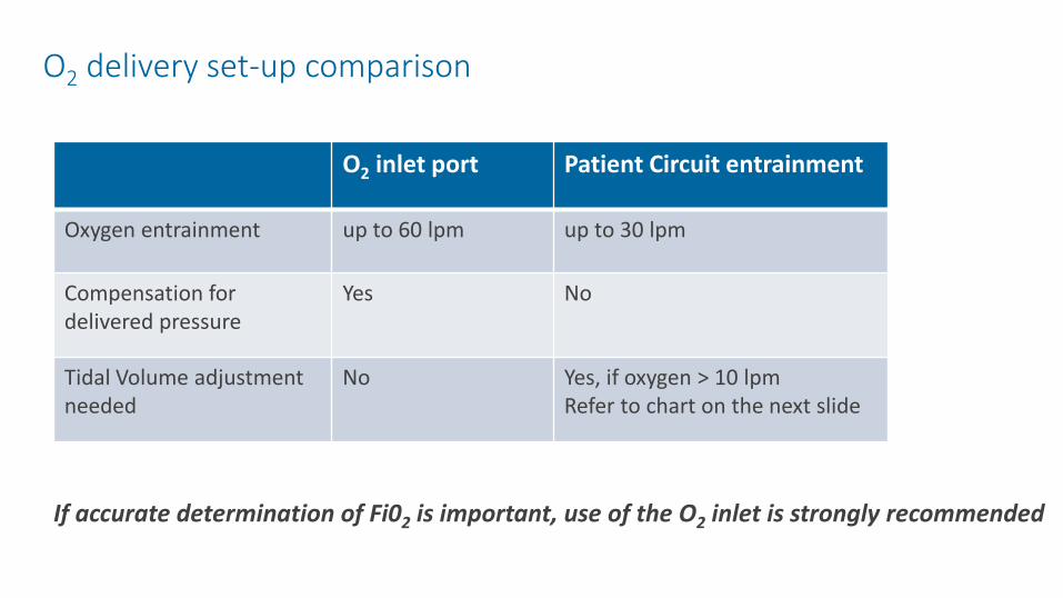
O2 delivery set-up comparison
O2 inlet port Patient Circuit entrainment
Oxygen entrainment up to 60 lpm up to 30 lpm
Compensation for delivered pressure
Yes No
Tidal Volume adjustment needed
No Yes, if oxygen > 10 lpmRefer to chart on the next slide
If accurate determination of Fi02 is important, use of the O2 inlet is strongly recommended
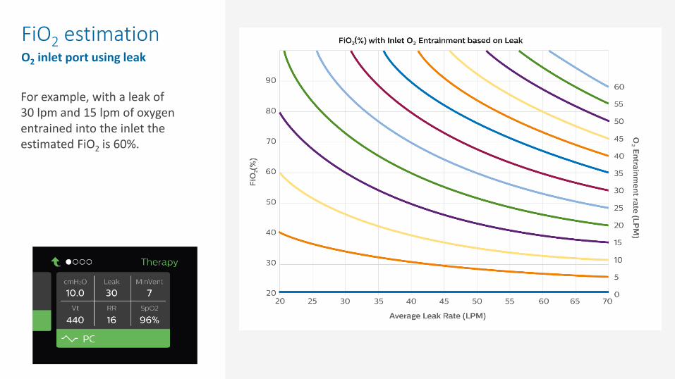
FiO2 estimationO2 inlet port using leak
For example, with a leak of 30 lpm and 15 lpm of oxygen entrained into the inlet the estimated FiO2 is 60%.
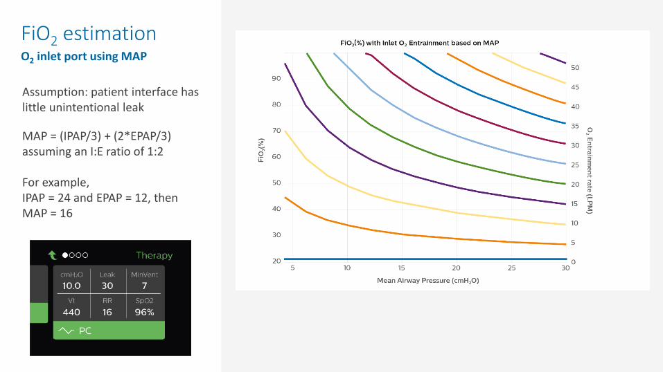
Assumption: patient interface has little unintentional leak
MAP = (IPAP/3) + (2*EPAP/3) assuming an I:E ratio of 1:2
For example,IPAP = 24 and EPAP = 12, then MAP = 16
FiO2 estimationO2 inlet port using MAP
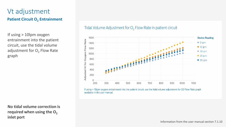
Vt adjustmentPatient Circuit O2 Entrainment
If using > 10lpm oxygen entrainment into the patient circuit, use the tidal volume adjustment for O2 Flow Rate graph
No tidal volume correction is required when using the O2inlet port
Information from the user manual section 7.1.10
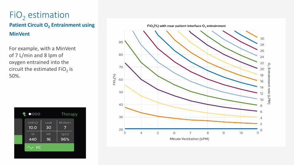
FiO2 estimationPatient Circuit O2 Entrainment using MinVent
For example, with a MinVentof 7 L/min and 8 lpm of oxygen entrained into the circuit the estimated FiO2 is 50%.
On-screen respiratory monitoring (pressure, tidal volume, RR, Minute Ventilation, leak and SpO2) as well as visual and audible alarms to provide pertinent therapy information.
Key monitoring and alarms

Therapy modes• CPAP• S• S/T• PC

Therapy modes: CPAP
Patient triggered and cycled breaths.
Pressure delivered during both inhalation and exhalation is the CPAP pressure setting.
All breaths are spontaneous
1
2
3
1
2
3
Continuous Positive Airway Pressure
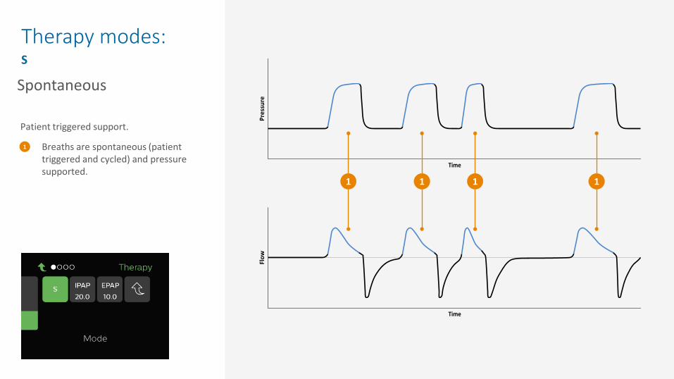
Therapy modes: S
Breaths are spontaneous (patient triggered and cycled) and pressure supported.
1
1
Patient triggered support.
1 1 1
Spontaneous
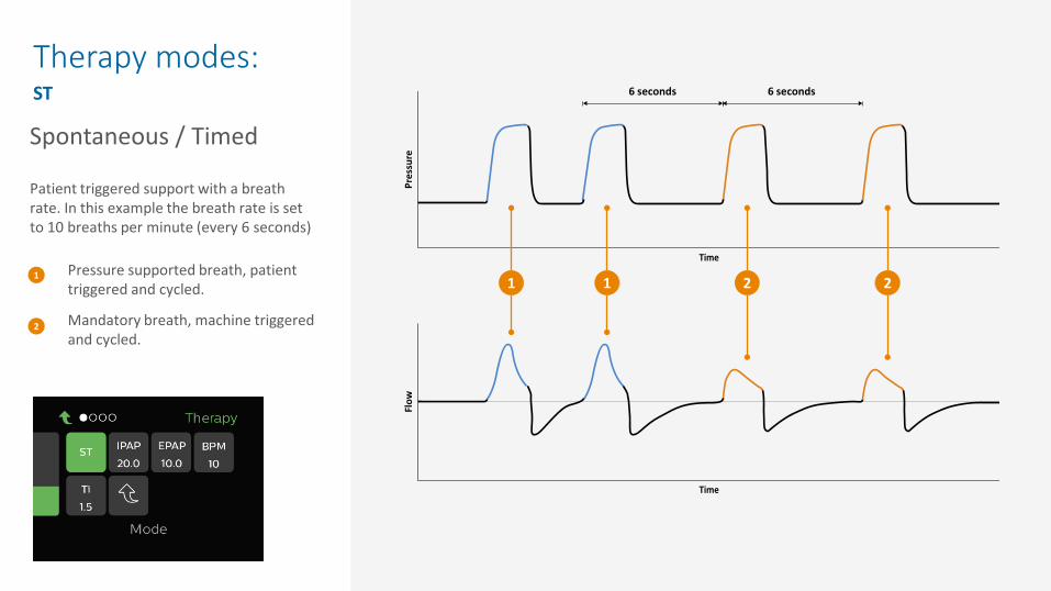
Therapy modes: ST
Pressure supported breath, patient triggered and cycled.
Mandatory breath, machine triggered and cycled.
1
2
Patient triggered support with a breath rate. In this example the breath rate is set to 10 breaths per minute (every 6 seconds)
6 seconds 6 seconds
1 1 2 2
Spontaneous / Timed
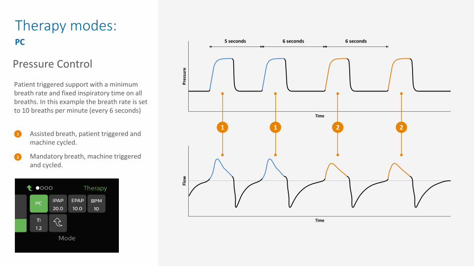
Therapy modes: PC
Assisted breath, patient triggered and machine cycled.
Mandatory breath, machine triggered and cycled.
1
2
Patient triggered support with a minimum breath rate and fixed inspiratory time on all breaths. In this example the breath rate is set to 10 breaths per minute (every 6 seconds)
6 seconds 6 seconds5 seconds
1 1 2 2
Pressure Control

Key monitoring• Therapy delivery• SpO2 connection• Alarm options
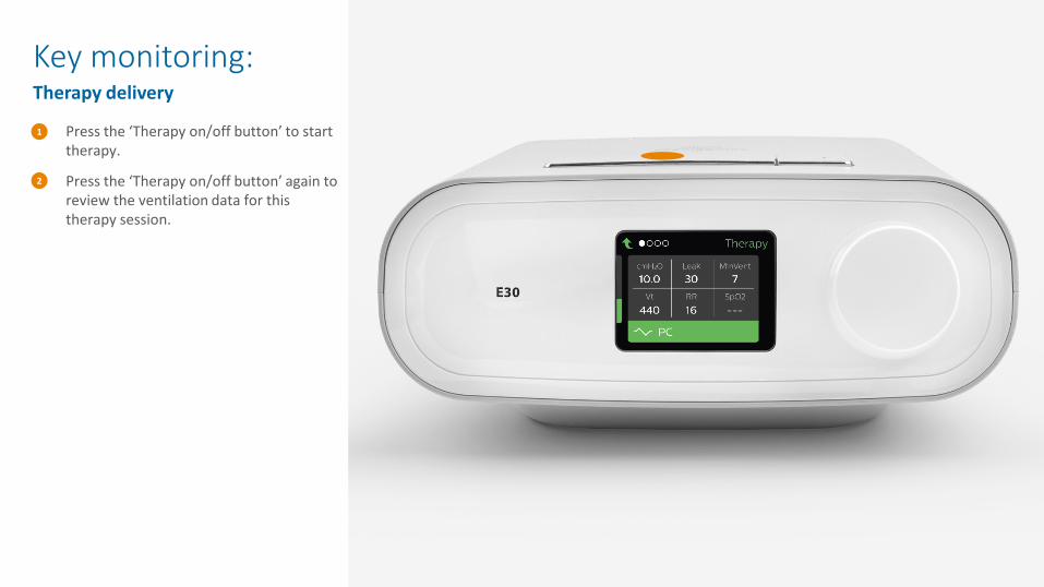
Key monitoring: Therapy delivery
Press the ‘Therapy on/off button’ to start therapy.
Press the ‘Therapy on/off button’ again to review the ventilation data for this therapy session.
1
2
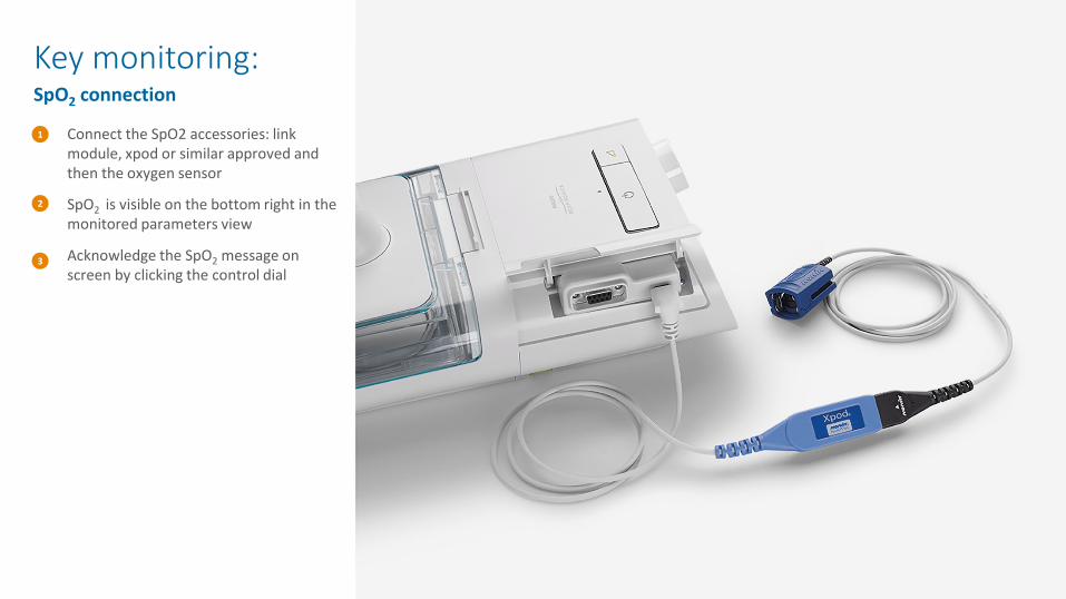
Key monitoring: SpO2 connection
Connect the SpO2 accessories: link module, xpod or similar approved and then the oxygen sensor
SpO2 is visible on the bottom right in the monitored parameters view
Acknowledge the SpO2 message on screen by clicking the control dial
1
2
3
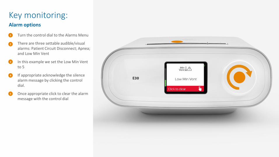
Key monitoring: Alarm options
Turn the control dial to the Alarms Menu
There are three settable audible/visual alarms: Patient Circuit Disconnect; Apnea; and Low Min Vent
In this example we set the Low Min Vent to 5
If appropriate acknowledge the silence alarm message by clicking the control dial.
Once appropriate click to clear the alarm message with the control dial
1
2
3
4
5

Visual alarms• Leak is less that Min Vent• Leak is less than 0• Excessive leak
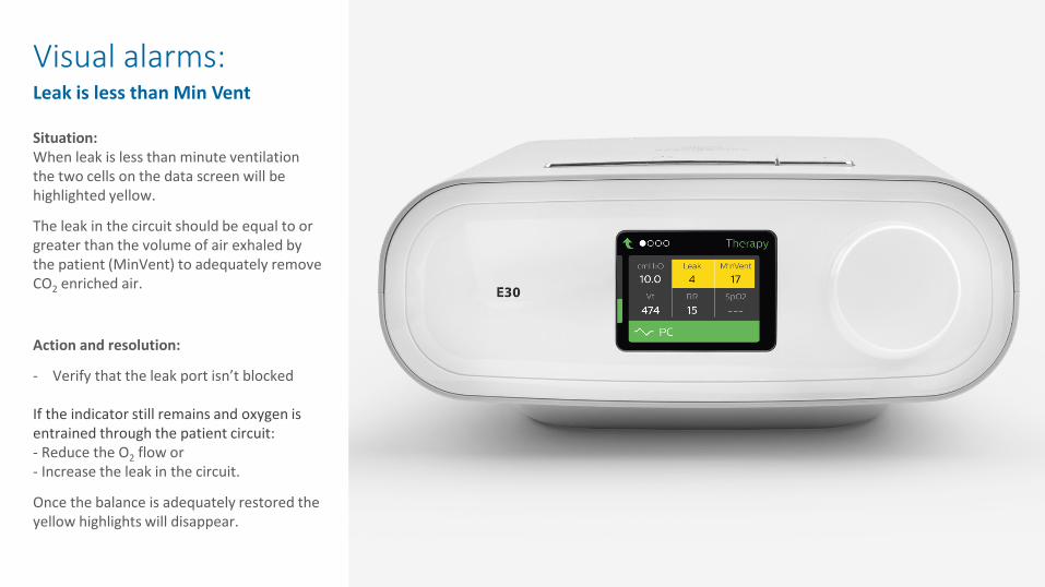
Visual alarms: Leak is less than Min Vent
Situation:When leak is less than minute ventilation the two cells on the data screen will be highlighted yellow.
The leak in the circuit should be equal to or greater than the volume of air exhaled by the patient (MinVent) to adequately remove CO2 enriched air.
Action and resolution:
- Verify that the leak port isn’t blocked
If the indicator still remains and oxygen is entrained through the patient circuit:- Reduce the O2 flow or- Increase the leak in the circuit.
Once the balance is adequately restored the yellow highlights will disappear.

Visual alarms: Leak is less than 0
Only applicable when oxygen is entrained directly into the patient circuit
Situation:When leak is less than 0 the cell will be highlighted orange. As per the indication above, Min Vent will be highlighted yellow because the minute ventilation is greater than the leak. Tidal volume will also be highlighted yellow because the negative leak reduces tidal volume accuracy.
A negative leak indicates extra oxygen in the circuit that is being wasted and not utilized by the patient.
Action and resolution:- Reduce the O2 flow or
- if unable to reduce the O2 flow then increase the leak.
Once the balance is adequately restored the color highlights will disappear.
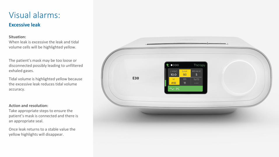
Visual alarms: Excessive leak
Situation:When leak is excessive the leak and tidal volume cells will be highlighted yellow.
The patient’s mask may be too loose or disconnected possibly leading to unfiltered exhaled gases.
Tidal volume is highlighted yellow because the excessive leak reduces tidal volume accuracy.
Action and resolution:Take appropriate steps to ensure the patient’s mask is connected and there is an appropriate seal.
Once leak returns to a stable value the yellow highlights will disappear.

Additional InformationProvider AccessHumidifier Use
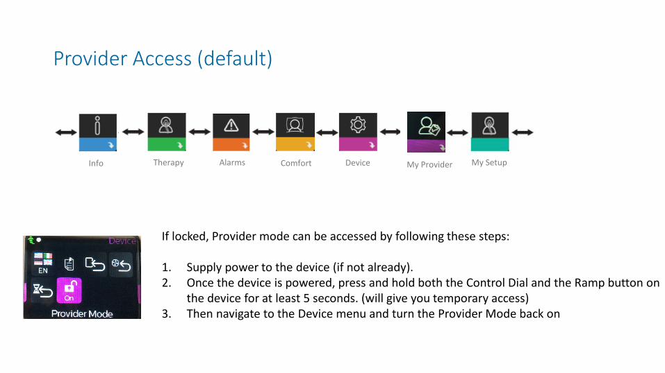
Provider Access (default)
If locked, Provider mode can be accessed by following these steps:
1. Supply power to the device (if not already). 2. Once the device is powered, press and hold both the Control Dial and the Ramp button on
the device for at least 5 seconds. (will give you temporary access)3. Then navigate to the Device menu and turn the Provider Mode back on
My SetupMy ProviderComfort DeviceAlarmsTherapyInfo
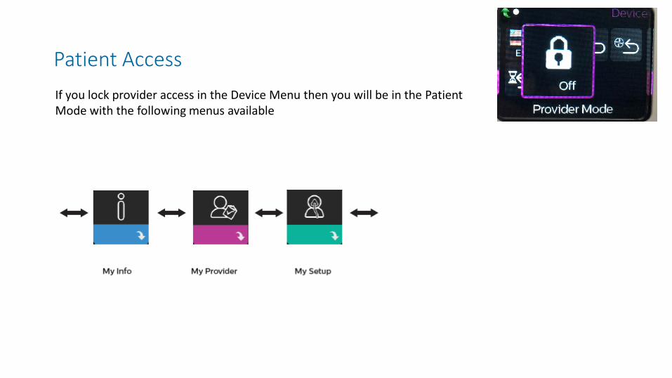
Patient Access If you lock provider access in the Device Menu then you will be in the Patient Mode with the following menus available
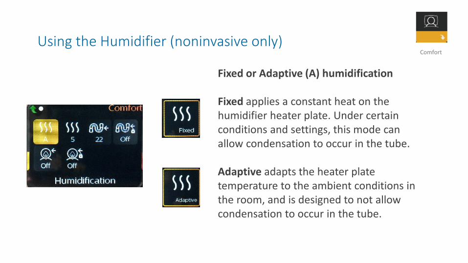
Using the Humidifier (noninvasive only)
Fixed or Adaptive (A) humidification
Fixed applies a constant heat on the humidifier heater plate. Under certain conditions and settings, this mode can allow condensation to occur in the tube.
Adaptive adapts the heater plate temperature to the ambient conditions in the room, and is designed to not allow condensation to occur in the tube.
Comfort
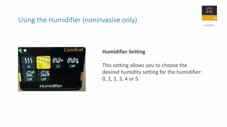
Using the Humidifier (noninvasive only)
Humidifier Setting
This setting allows you to choose the desired humidity setting for the humidifier: 0, 1, 2, 3, 4 or 5.
Comfort
Easy to use
Designed for your safety
Optimized oxygen delivery
Key monitoring and alarms