Embed Size (px)
Citation preview
UNIT-II
Single Phase Circuits
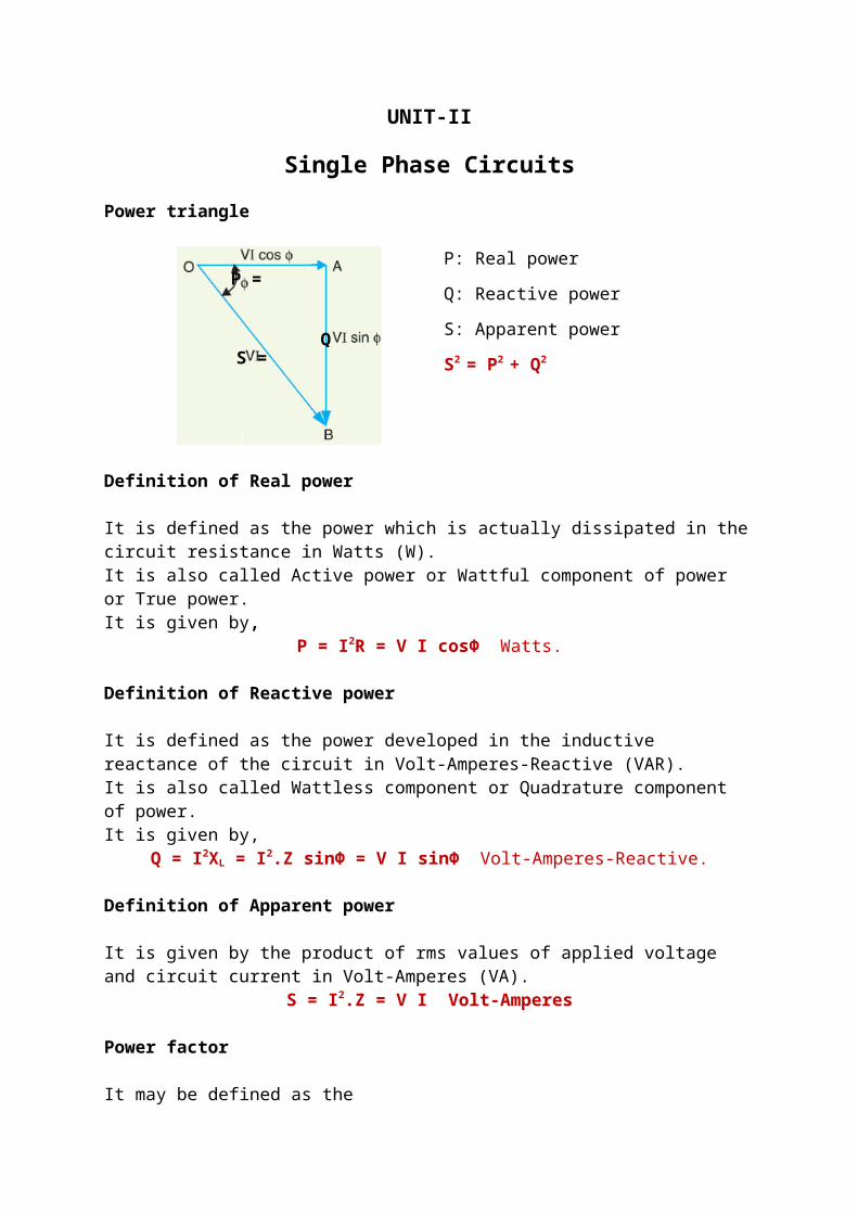
Power triangle
P: Real power
Q: Reactive power
S: Apparent power
S2 = P2 + Q2
Definition of Real power
It is defined as the power which is actually dissipated in the circuit resistance in Watts (W). It is also called Active power or Wattful component of power or True power. It is given by,
P = I2R = V I cosΦ Watts.
Definition of Reactive power
It is defined as the power developed in the inductive reactance of the circuit in Volt-Amperes-Reactive (VAR). It is also called Wattless component or Quadrature component of power. It is given by,
Q = I2XL = I2.Z sinΦ = V I sinΦ Volt-Amperes-Reactive.
Definition of Apparent power
It is given by the product of rms values of applied voltage and circuit current in Volt-Amperes (VA).
S = I2.Z = V I Volt-Amperes
Power factor
It may be defined as the 1) Cosine of the angle of lead or lag.
2) The ratio of R to Z. cosΦ= RZ
3) The ratio of True power to Apparent power. cosΦ= PS
= WVA
The Maximum value of power factor=1.
Analysis of AC circuits
P =
Q = S =

R
i
v
vi
1. Analysis of Pure Resistive circuit:
Let the voltage vector be taken as the reference. Then, the angle of lead/lag, Φ=0
Therefore, v=V m sin (ωt ± 0).
By Ohm’s law, instantaneous value of current through the circuit is given by,
i= vR
=V msin (ωt )
R=Im sin ¿)
From the above equations, the phase difference between between v and i = 0. i.e,
i is in phase with v.
The instantaneous power consumed by resistance R is given by,
p=v .i=V msin (ωt )( Im sin ωt)
p=V m
2
Rsin 2 (ωt )=
V m2
R(1−cos2 ωt )
2
p=V m
2
R−
V m2
2 Rcos2ωt
2
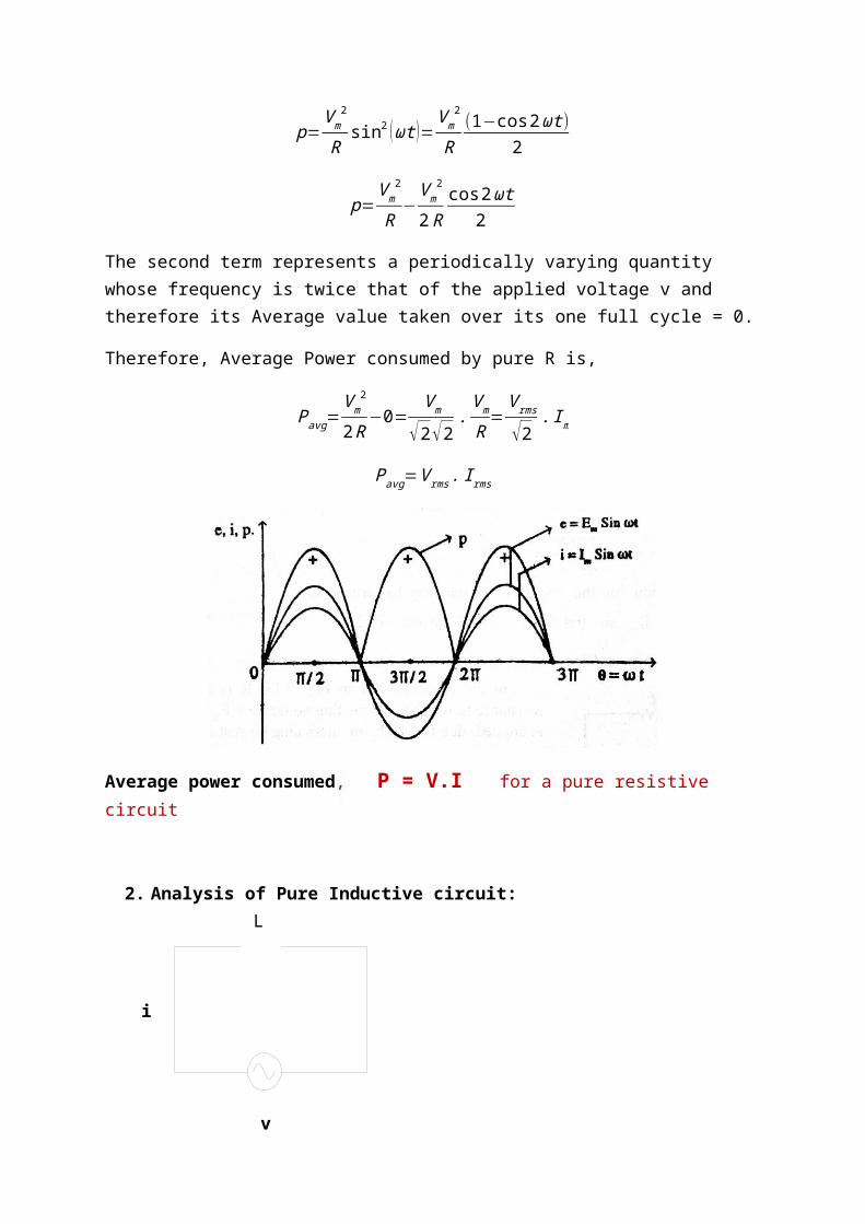
The second term represents a periodically varying quantity whose frequency is twice that of the applied voltage v and therefore its Average value taken over its one full cycle = 0.
Therefore, Average Power consumed by pure R is,
Pavg=V m
2
2R−0=
V m
√2√2.V m
R=
V rms
√2. Im
Pavg=V rms . Irms
v
L
i v
i
Average power consumed, P = V.I for a pure resistive circuit
2. Analysis of Pure Inductive circuit:
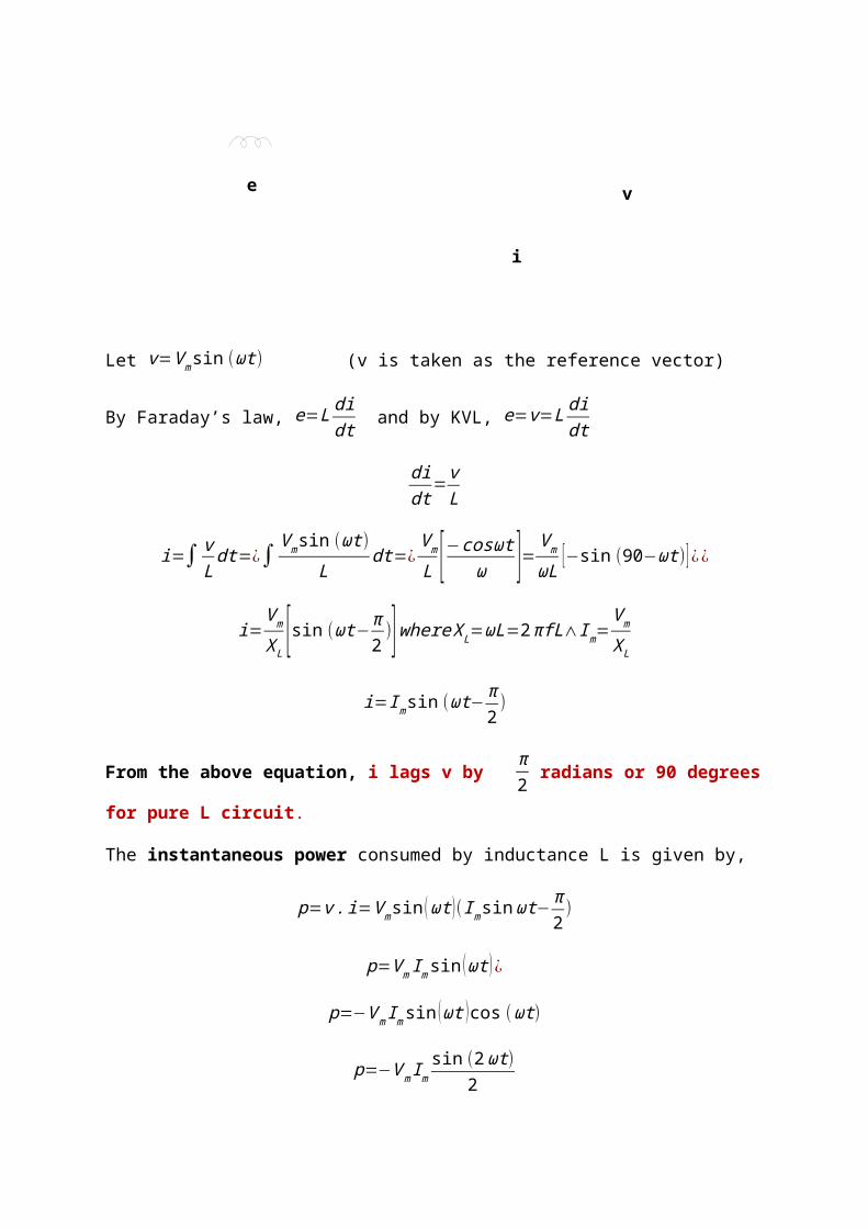
Let v=V m sin (ωt) (v is taken as the reference vector)
By Faraday’s law, e=L didt and by KVL, e=v=L di
dt
didt
= vL
i=∫ vL
dt=¿∫ V m sin (ωt )L
dt=¿V m
L [−cosωtω ]=V m
ωL [−sin (90−ωt)] ¿¿
i=V m
XL[sin (ωt−π
2)]where X L=ωL=2πfL∧Im=
V m
X L
i=Im sin (ωt−π2)
From the above equation, i lags v by π2 radians or 90 degrees for pure L circuit.
e
v
i
The instantaneous power consumed by inductance L is given by,
p=v .i=V msin (ωt )( Im sin ωt−π2)
p=V m Im sin (ωt )¿
p=−V m Im sin (ωt ) cos (ωt)
p=−V m Imsin (2ωt)
2
This represents a periodically varying quantity whose frequency is twice that of the applied voltage v and therefore its Average value taken over its one full cycle = 0. Therefore, Average Power consumed by pure L is,
Pavg=0
Average power consumed, P = 0 for a pure inductive circuit.
3. Analysis of Pure Capacitive circuit:
v
C
i
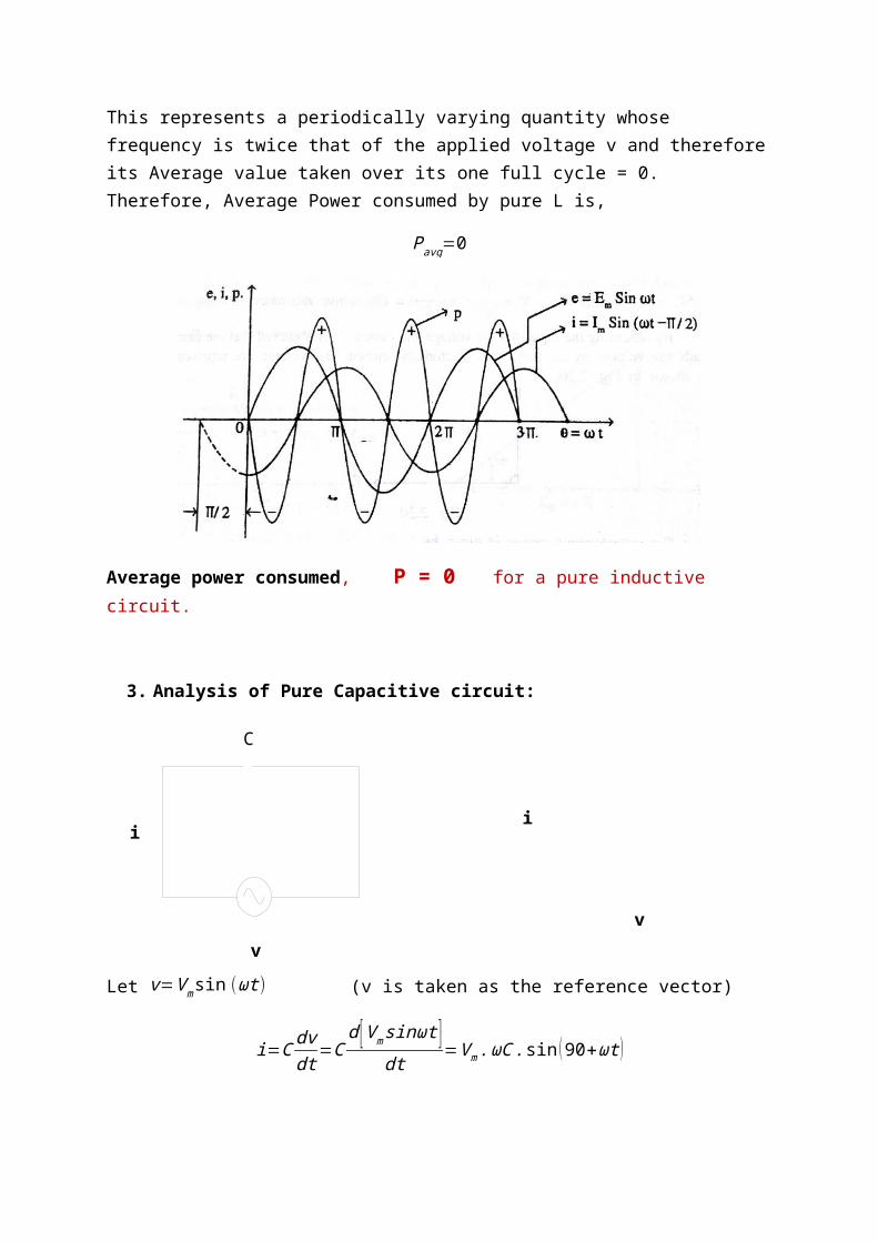
Let v=V m sin (ωt) (v is taken as the reference vector)
i=C dvdt
=Cd [V m sinωt ]
dt=V m.ωC . sin ( 90+ωt )
i=V m
XC[sin (ωt+ π
2)]where XC=
1ωC
= 12πfC
∧Im=V m
XC
i=Im sin (ωt+ π2)
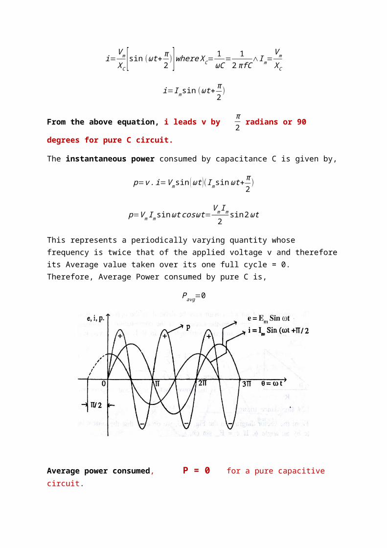
From the above equation, i leads v by π2 radians or 90 degrees for pure C circuit.
The instantaneous power consumed by capacitance C is given by,
p=v .i=V msin (ωt )(Im sin ωt+ π2)
p=V m Im sin ωt cosωt=V m Im
2sin 2ωt
This represents a periodically varying quantity whose frequency is twice that of the applied voltage v and therefore its Average value taken over its one full cycle = 0. Therefore, Average Power consumed by pure C is,
Pavg=0
Average power consumed, P = 0 for a pure capacitive circuit.
I
ELE
ER
Φ
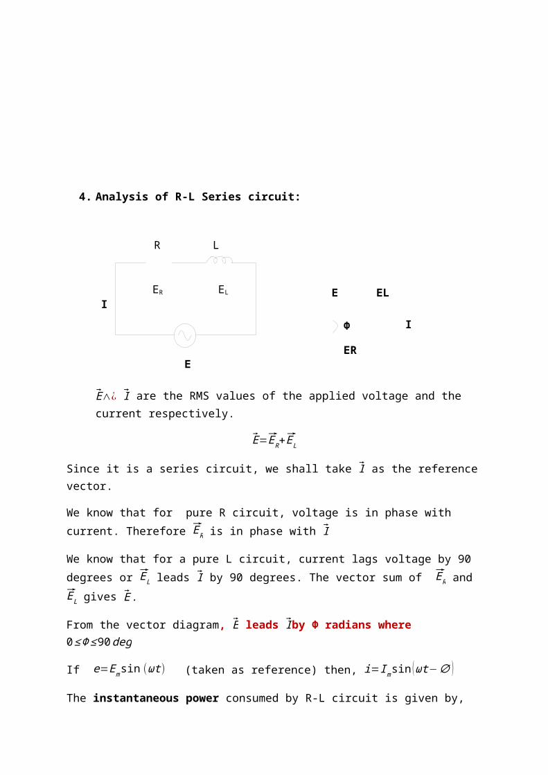
4. Analysis of R-L Series circuit:
E∧¿ I are the RMS values of the applied voltage and the current respectively.
E=ER+ EL
Since it is a series circuit, we shall take I as the reference vector.
We know that for pure R circuit, voltage is in phase with current. Therefore ER is in phase with I
We know that for a pure L circuit, current lags voltage by 90 degrees or EL leads I by 90 degrees. The vector sum of ER and EL gives E .
From the vector diagram, E leads Iby Φ radians where 0≤Φ≤ 90deg
If e=Emsin (ωt ) (taken as reference) then, i=Im sin (ωt−∅ )
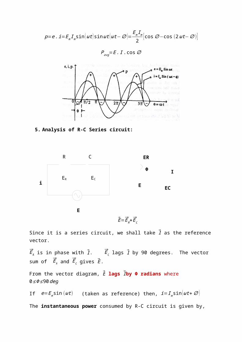
The instantaneous power consumed by R-L circuit is given by,
p=e . i=Em Imsin (ωt ) sin ωt (ωt−∅ )=Em Im
2 [cos∅−cos (2ωt−∅ )]
Pavg=E . I .cos∅
E
L
I
R
ER EL
I
ECE
ER
Φ
5. Analysis of R-C Series circuit:
E=ER+ EC
Since it is a series circuit, we shall take I as the reference vector.
ER is in phase with I . EC lags I by 90 degrees. The vector sum of ER and EC gives E .
From the vector diagram, E lags Iby Φ radians where 0≤ Φ≤ 90deg
If e=Emsin (ωt ) (taken as reference) then, i=Im sin (ωt+∅ )
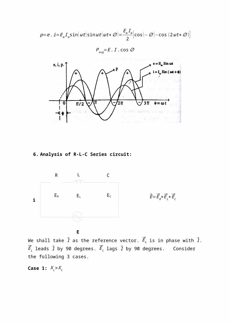
The instantaneous power consumed by R-C circuit is given by,
p=e . i=Em Imsin (ωt ) sin ωt (ωt+∅ )=Em Im
2 [cos (−∅ )−cos (2ωt+∅ )]
Pavg=E . I .cos∅
E
C
i
R
ER EC
6. Analysis of R-L-C Series circuit:
E=ER+ EL+ EC
We shall take I as the reference vector. ER is in phase with I . EL leads I by 90 degrees. EC lags I by 90 degrees. Consider the following 3 cases.
Case 1: X L>XC
E
C
i
R
ER ECEL
L
This implies that IX L> IXC∨EL>EC
It can be seen from the vector diagram that V leads I by Φ radians or I lags E by Φ radians.
Hence the circuit behaves as a series R-L circuit.
If e=Emsin (ωt ) then, i=Im sin(ωt ¿−∅ )¿ and
Pavg=E . I .cos∅
Case 2: X L<XC
This implies that IX L< IXC∨EL<EC
It can be seen from the vector diagram that E lags I by Φ radians or I leads E by Φ radians.
The circuit behaves as a series R-C circuit.
If e=Emsin (ωt ) then, i=Im sin(ωt ¿+∅ )¿ and
Pavg=E . I .cos∅
Case 3: X L=XC
This implies that IX L=IX C∨EL=EC

It can be seen from the vector diagram that I is in phase with E.
Circuit behaves as a pure R circuit.
If e=Emsin (ωt ) then, i=Im sin(ωt ¿)¿ and
Pavg=E . I
Concept of power factor improvement:
Power factor plays an important role in AC circuits since power consumed depends upon it.
It is clear from the above that for fixed power and voltage, the load current is inversely proportional to the power factor. Lower the power factor, higher is the load current and vice-versa. A power factor less than unity results in greater conductor size, large copper losses and poor voltage regulation.
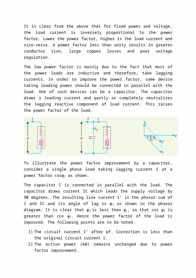
The low power factor is mainly due to the fact that most of the power loads are inductive and therefore, take lagging currents. In order to improve the power factor, some device taking leading power should be connected in parallel with the load. One of such devices can be a capacitor. The capacitor draws a leading current and partly or completely neutralizes the lagging reactive component of load current. This raises the power factor of the load.
To illustrate the power factor improvement by a capacitor, consider a single phase load taking lagging current I at a power factor cosϕ1 as shown.

The capacitor C is connected in parallel with the load. The capacitor draws current IC which leads the supply voltage by 90 degrees. The resulting line current I’ is the phasor sum of I and IC and its angle of lag is ϕ2 as shown in the phasor diagram. It is clear that ϕ2 is less than ϕ1, so that cos ϕ2 is greater than cos ϕ1. Hence the power factor of the load is improved. The following points are to be noted.
1) The circuit current I’ after pf. Correction is less than the original circuit current I.2) The active power (kW) remains unchanged due to power factor improvement.
Numericals:
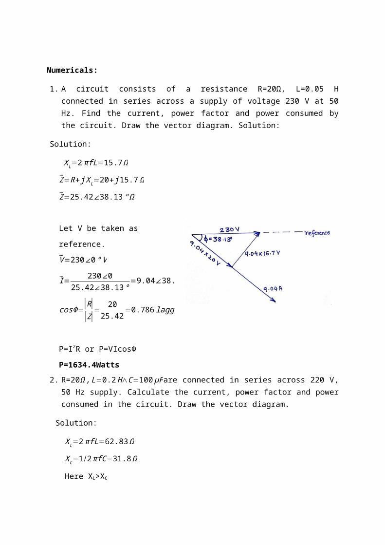
1. A circuit consists of a resistance R=20Ω, L=0.05 H connected in series across a supply of voltage 230 V at 50 Hz. Find the current, power factor and power consumed by the circuit. Draw the vector diagram. Solution:
Solution:
X L=2πfL=15.7Ω
Z=R+ j X L=20+ j 15.7 Ω
Z=25.42∠38.13 ° Ω
Let V be taken as reference. V=230∠0 ° V I= 230∠ 0
25.42∠38.13 °=9.04∠38.13 ° A
cosΦ=|R||Z|
= 2025.42
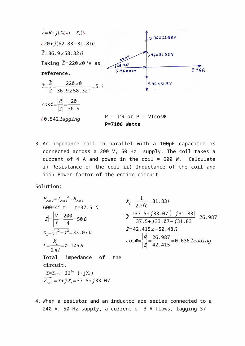
=0.786 lagging P=I2R or P=VIcosΦP=1634.4Watts2. R=20Ω , L=0.2 H∧C=100 µFare connected in series across 220 V, 50 Hz supply. Calculate the current, power factor and power consumed in the circuit. Draw the vector diagram.
Solution: X L=2πfL=62.83 Ω
XC=1/2πfC=31.8 Ω
Here XL>XC
Z=R+ j( X ¿¿ L−X C)¿
¿20+ j (62.83−31.8)Ω
Z=36.9∠58.32 ΩTaking E=220∠ 0°V as reference,I= E
Z= 220∠0
36.9∠58.32 °=5.96∠58.32 A
cosΦ=|R||Z|
= 2036.9
¿0.542 lagging P = I2R or P = VIcosΦP=7106 Watts3. An impedance coil in parallel with a 100µF capacitor is connected across a 200 V, 50 Hz supply. The coil takes a current of 4 A and power in the coil = 600 W. Calculate i) Resistance of the coil ii) Inductance of the coil and iii) Power factor of the entire circuit.Solution:
Pcoil=I coil2 . Rcoil 600=42.r r=37.5 Ω
|Z|=|V||I|
=2004
=50Ω
X L=√Z2−r2=33.07 Ω
L=XL
2πf=0.105 HTotal impedance of the circuit, Z=Zcoil IIle (-jXc)
Zcoil=r+ j X L=37.5+ j33.07
XC= 12 πfC
=31.83 H
Z=(37.5+ j 33.07 ) (− j 31.83 )37.5+ j 33.07− j31.83
=26.987− j32.72 Ω
Z=42.415∠−50.48 Ω
cosΦ=|R||Z|
=26.98742.415
=0.636 leading
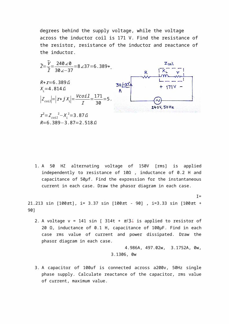
4. When a resistor and an inductor are series connected to a 240 V, 50 Hz supply, a current of 3 A flows, lagging 37 degrees behind the supply voltage, while the voltage across the inductor coil is 171 V. Find the resistance of the resistor, resistance of the inductor and reactance of the inductor.
Z=VI= 240∠0
30∠−37=8∠37=6.389+ j 4.814
R+r=6.389ΩX L=4.814 Ω
|Zcoil|=|r+ j XL|=Vcoil
I=171
30=5.7 Ω
r2=Zcoil2−X L
2=3.87 ΩR=6.389−3.87=2.518Ω
1. A 50 HZ alternating voltage of 150V [rms] is applied independently to resistance of 10Ω , inductance of 0.2 H and capacitance of 50µf. Find the expression for the instantaneous current in each case. Draw the phasor diagram in each case.
I= 21.213 sin [100 πt], i= 3.37 sin [100πt - 90] , i=3.33 sin [100πt + 90]
2. A voltage v = 141 sin [ 314t + π /3¿ is applied to resistor of 20 Ω, inductance of 0.1 H, capacitance of 100µF. Find in each case rms value of current and power dissipated. Draw the phasor diagram in each case.
4.986A, 497.02w, 3.1752A, 0w, 3.1306, 0w
3. A capacitor of 100uf is connected across a200v, 50Hz single phase supply. Calculate reactance of the capacitor, rms value of current, maximum value.
31.8 Ω, 6.29A, 8.87A
4. A current wave is represented by i= 20 sin [215t]. Calculate the maximum and rms values of current and its frequency.
20A, 14.14A, 9.4hz
5. A choke coil of negligible resistance draws a current of 4.5A when connected to 230v, 50hz mains. Find its inductive reactance and inductance in henry.
51.11 Ω, 0.163h6. A current of 10A leading its voltage by 90 degrees is required from a 230V, 50hz supply,
using a bank of capacitors. What should this capacitance be?138.4uf
7. A capacitor connected to a 230V, 50hz supply draws 15A. What current will it draw when capacitance and frequency are both reduced to half.
3.75A
8. An inductor having a reactance of 15Ω and negligible resistance is connected across a 230V, 50hz supply. Draw to scale for one cycle curves of voltage and current.
9. An alternating voltage of 200V, 50hz supply is applied to a coil of negligible resistance and inductance 0.1h. Find the current drawn by the coil.
6.36A10. Find the current that will flow through a coil of negligible resistance and inductance of 60mh
when connected to 230V, 50hz supply.12.2A
Three phase circuits
Advantages of 3 phase systems:
1. A 3 phase apparatus is more efficient than a single phase apparatus.2. A 3 phase apparatus costs less than a single phase apparatus of the same capacity.3. A 3 phase apparatus is smaller in size than a single phase apparatus of the same
capacity and hence requires less material for construction.4. To transmit the same amount of power over the same distance under the same power
loss, the conductor material required is less for a 3 phase system than for a single phase system.
5. 3 phase motors are self starting whereas single phase motors are not self starting and hence require a starting mechanism.
6. Three phase motors produce uniform torque whereas the torque in a single phase motor is pulsating.
7. When single phase generators are connected in parallel, they give rise to harmonics, whereas, 3 phase generators can be conveniently connected in parallel without giving rise to harmonics.
8. In the case of a three phase star system, two different voltages can be obtained, one between lines and the other between line and phase, whereas only one voltage can be obtained in a single phase system.
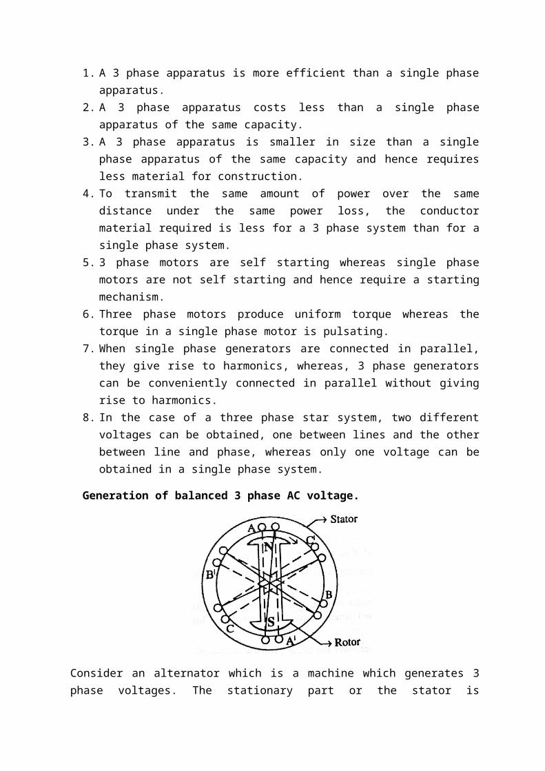
Generation of balanced 3 phase AC voltage.
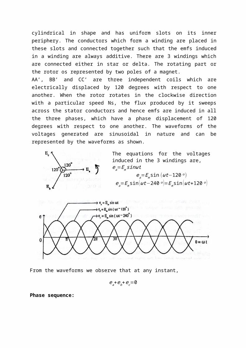
Consider an alternator which is a machine which generates 3 phase voltages. The stationary part or the stator is cylindrical in shape and has uniform slots on its inner periphery. The conductors which form a winding are placed in these slots and connected together such that the emfs induced in a winding are always additive. There are 3 windings which are connected either in star or delta. The rotating part or the rotor os represented by two poles of a magnet.AA’, BB’ and CC’ are three independent coils which are electrically displaced by 120 degrees with respect to one another. When the rotor rotates in the clockwise direction with a particular speed Ns, the flux produced by it sweeps across the stator conductors and hence emfs are induced in all the three phases, which have a phase displacement of 120 degrees with respect to one another. The waveforms of the voltages generated are sinusoidal in nature and can be represented by the waveforms as shown.
The equations for the voltages induced in the 3 windings are,ea=Em sinωt
ea=Emsin (ωt−120ᵒ )ea=Emsin ( ωt−240 ᵒ )=Em sin (ωt+120 ᵒ )
From the waveforms we observe that at any instant,
ea+eb+ec=0
Ec
Ea
Eb
Ecn
Ean
Ebn
Phase sequence:
It is defined as the order in which the maximum values of the 3 phase voltages occur.
Balanced 3 phase supply:
A 3 phase supply is said to be balanced when all the 3 voltages have the same magnitude but differ in phase by 120ᵒ with respect to each other.
Balanced 3 phase load:
A 3 phase load is said to be balanced when the impedances of all the 3 phases are exactly the same. Here the magnitude of the currents in the 3 phases will be equal to each other but the currents differ in phase by 120 degrees with respect to each other.
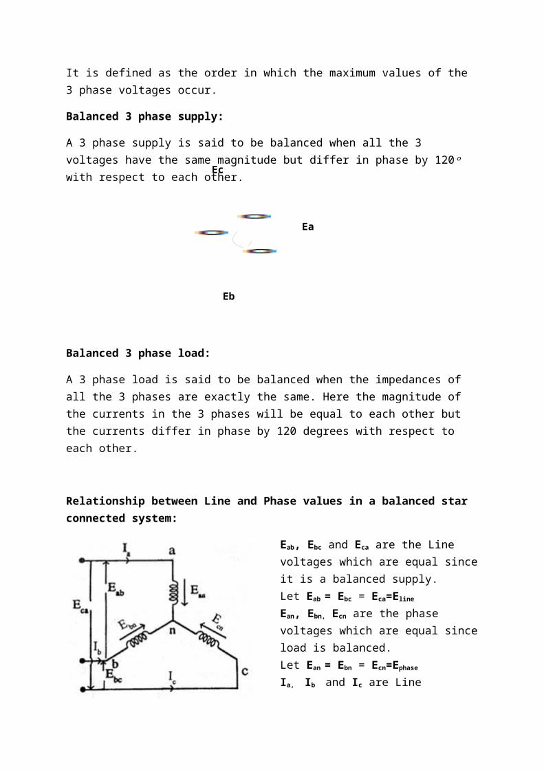
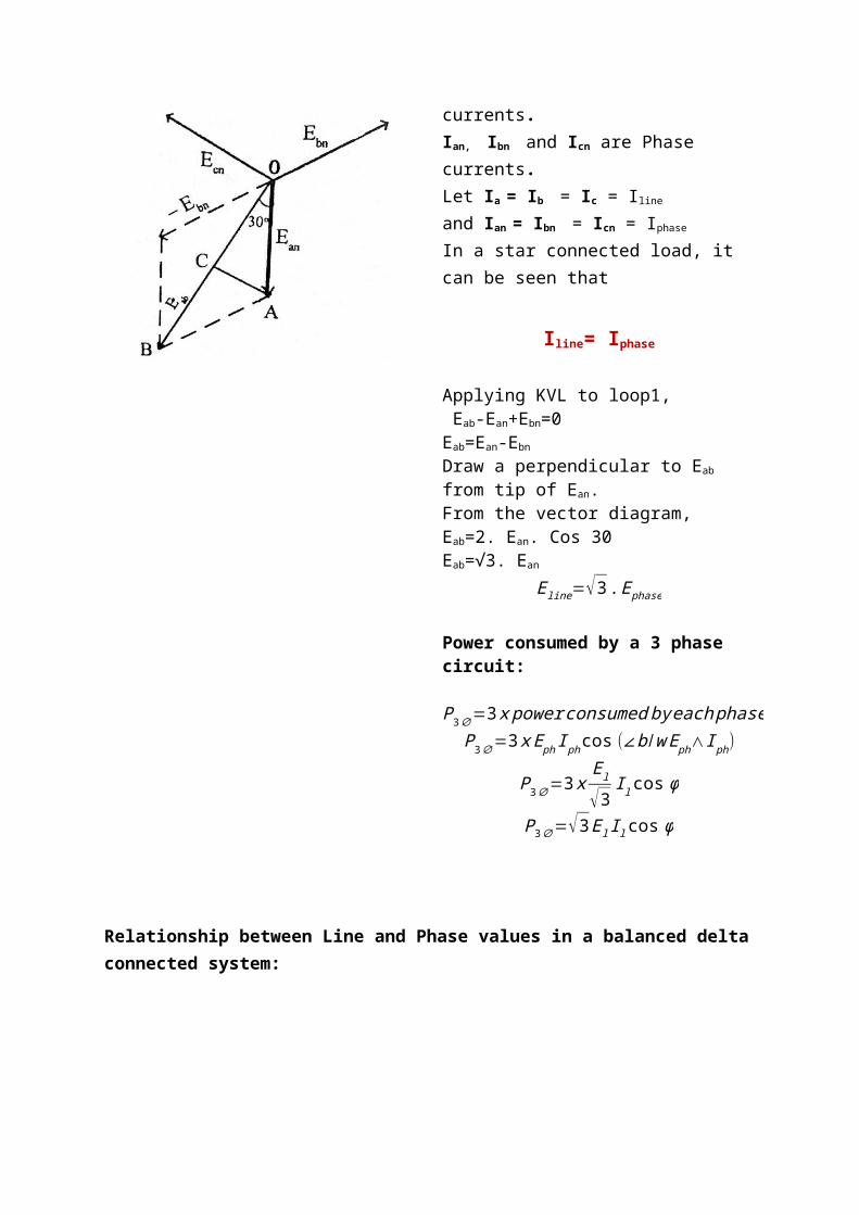
Relationship between Line and Phase values in a balanced star connected system:
Eab, Ebc and Eca are the Line voltages which are equal since it is a balanced supply.Let Eab = Ebc = Eca=Eline
Ean, Ebn, Ecn are the phase voltages which are equal since load is balanced.Let Ean = Ebn = Ecn=Ephase
Ia, Ib and Ic are Line currents.Ian, Ibn and Icn are Phase currents.Let Ia = Ib = Ic = Iline
and Ian = Ibn = Icn = Iphase
In a star connected load, it can be seen that
Iline= Iphase
Applying KVL to loop1, Eab-Ean+Ebn=0Eab=Ean-Ebn
Draw a perpendicular to Eab from tip of Ean.
Eab
Ebc
Eca
From the vector diagram,Eab=2. Ean. Cos 30Eab=√3. Ean
Eline=√3 . Ephase
Power consumed by a 3 phase circuit:
P3∅=3 x power consumed by each phaseP3∅=3 x Eph I phcos (∠b /w Eph∧I ph)
P3∅=3 xEl
√3I l cos ϕ
P3∅=√3 El Il cos ϕ
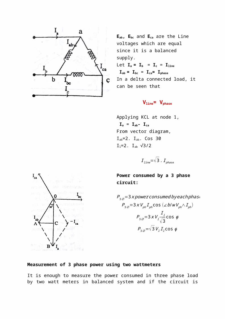
Relationship between Line and Phase values in a balanced delta connected system:
Eab, Ebc and Eca are the Line voltages which are equal since it is a balanced supply.Let Ia = Ib = Ic = Iline
Iab = Ibc = Ica= Iphase
In a delta connected load, it can be seen that
Vline= Vphase
Applying KCL at node 1, Ia = Iab- Ica
From vector diagram, Iab=2. Iab. Cos 30Il=2. Iab √3/2
I line=√3 . I phase
Power consumed by a 3 phase circuit:
P3∅=3 x power consumed by each phaseP3∅=3 x V ph I phcos (∠b /w V ph∧I ph)
P3∅=3 x V l
I l
√3cos ϕ
P3∅=√3V l I l cos ϕ
Measurement of 3 phase power using two wattmeters
It is enough to measure the power consumed in three phase load by two watt meters in balanced system and if the circuit is balanced we can also find the power factor from the readings of the power factor from the readings of the two watt meters.
Consider a star connected load.
Here we analyze the measurement of power when the load is star connected. The following assumptions are made.
i) The 3 phase supply to which the load is connected is balanced.ii) The phage sequence is ABCiii) The load is balancediv) The load is R-L in nature
For Wattmeter 1
Current measured by W1=Ia
Voltage measured = EAB = (Ean-Ebn)
But the phase difference between EAB & Ia is (300-f)
Wattmeter W1=Ia EAB cos(300-f)--------------------------(1)
Similarly, current through W2 = Ib
Voltage across W2 = ECB = (- Ebn+Ecn)
Here phase difference is (300 + f)
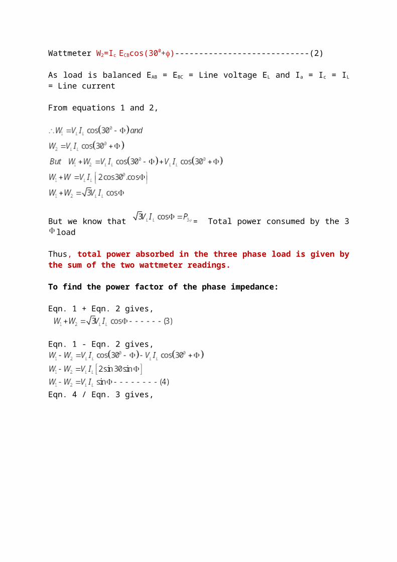
Wattmeter W2=Ic ECBcos(300+f)----------------------------(2)
As load is balanced EAB = EBC = Line voltage EL and Ia = Ic = IL = Line current
From equations 1 and 2,
But we know that = Total power consumed by the 3 load
Thus, total power absorbed in the three phase load is given by the sum of the two wattmeter readings.
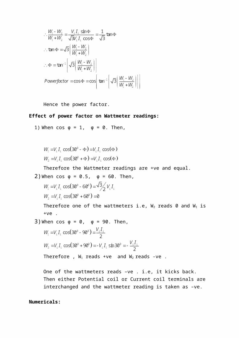
To find the power factor of the phase impedance:
Eqn. 1 + Eqn. 2 gives,
Eqn. 1 - Eqn. 2 gives,
Eqn. 4 / Eqn. 3 gives,
Hence the power factor.
Effect of power factor on Wattmeter readings:
1) When cos ϕ = 1, ϕ = 0. Then,
Therefore the Wattmeter readings are +ve and equal.2) When cos ϕ = 0.5, ϕ = 60. Then,
Therefore one of the wattmeters i.e, W2 reads 0 and W1 is +ve .3) When cos ϕ = 0, ϕ = 90. Then,
Therefore , W1 reads +ve and W2 reads -ve .
One of the wattmeters reads –ve . i.e, it kicks back. Then either Potential coil or Current coil terminals are interchanged and the wattmeter reading is taken as –ve.
Numericals:
1) Two wattmeters measure total power in a 3 phase circuit and are correctly connected. One wattmeter reads 4800 W and the other reads backwards. On reversing the connection of the latter, it reads 400 W. What is the total power and power factor.
Solution:
W1= 4800 W, W2 = - 400 WP3ϕ = W1+W2= 4400 W
2) Three identical coils having a resistance of 10 Ω and an inductance of 0.05 H each are connected in star across a 3 phase, 400 V, 50 Hz., balanced supply. Calculate the load current and power consumed. What will be the readings of the two wattmeters connected to measure the total power?
Solution:
P3ϕ = W1+W2= 4400 W ----------(1)

3) A 3 phase star connected load draws a load current of 25 A. The load kVA and kW are 20 and 16 respectively. Find the reading on each of the two wattmeters used to measure the 3 phase power.
Solution:
Load kVA, ie, apparent power, S=20 kVA
Load kW, ie, active power, P =16 kW
4) The power flowing in a 440 V, 3ϕ, 3 wire balanced load system is measured by 2 wattmeter method. The reading in the wattmeter A is 750 W and in wattmeter B is 1500 W. What is the power factor of the system and load current per phase?
Solution:
5) Two wattmeters are connected to measure the input of a 15 H.P, 50 Hz, 3 phase Induction motor at full load. The full load efficiency and power factor are 0.9 and 0.8 lagging respectively. Find the readings of the 2 wattmeters.
Solution:
Power output by the 3 phase induction motor at full load = 15 H.P = 15 x 746W Power output = 11.19kW
Reactive power= (w1-w2)* root 3 kvar
Tutorial on 3-phase AC
1. A delta connected load consists of a resistance of 10Ω and a capacitance of 100 µF in each
phase. A supply of 410 V at 50 Hz is applied to the load. Find the line current, power factor
and power consumed by the load.
2. A 3-phase star connected load draws a line current of 25 A. A load of KVA and KW are 20
and 16 resp. Find the reading on each of the two watt meter used to measure the 3-phase
power.
3. Two watt meter are connected to measure the input to a 3-phase, 12 HP, 50 Hz. In which
works at a full load η of 85% and a power factor of 0.8. find the reading of two watt meter.
4. 3 coils each having aresistance of 20Ω and an inductive reactance of 15Ω are connected in
star to a 400V 3-phase 50Hz supply… calculate line current, power factor, power supplied.
5. If two watt meters are used to measure 3-phase power in a balanced circuit, what would be
the reading in each watt meter? If ф=60 ф=30 ф=0 ф=90.
6. A 3 phase,400V motor has an output of 50HP.It operates with an efficiency of 90%
and a pf of 0.8.Find the reading of two wattmeters connected to measure the input
power.
7. A balanced star connected load of (8+j6) ohms per phase is connected to a 3 phase,
230V supply. Find the line currents, pf, power, reactive volt amperes and total volt
amperes.
8. 3-phase delta connected load consumes a power of 100KW taking a lagging current of 200A
at a line voltage of 400V,50Hz. Find the parameter of each phase.


![IJRARijrar.org/papers/IJRAR_222966.docx · Web viewThere are certain power quality issue we faced because of unbalanced and inductive loads in the distribution system [1].This is](https://img.pdfslide.us/doc/110x75/6089282edf78cb61dd029669/web-view-there-are-certain-power-quality-issue-we-faced-because-of-unbalanced-and.jpg)