Embed Size (px)
Citation preview
M0423.5 rev. 1 del 16.01.09 NC
Phase Motion Control technology for DD wind power
Generals
Wind power plants are characterized by mechanical energy being available at low speed
with very significant torque. On the other hand, the physical size (and cost) of electric
generators depends critically on the torque, not on the converted power. Consequently,
the conversion of wind power into electric energy can be performed in two ways:
1. Traditional approach: in order to avoid the use of a large and massive generator,
a geabox speed multiplier is interposed between the low speed turbine and a
conventional high speed generator;
2. DD approach: a suitably large, but optimized, low speed generator is coupled
directly to the low speed turbine.
The gearbox solution, which requires just a composition of standard or semi standard
technologies, was favored in the initial phase of wind power development. This solution,
however, is saddled with important disadvantages:
• Reliability: in the last 20 years, the average lifetime of wind rated gearboxes was
found to be close to 11 years. A gearbox failure usually causes an out of service of
over one year and 11 years is very close to the payback time of the typical wind
farm investment
• Availability: Due to internal friction and inertia, gearbox multiplied units cannot
tarck wind gusts so invariable weather conditions, it was found that DD units
produce substantially more electric power, all other conditions being equal
• Maintenance and environment: large gearboxes require periodic maintenance
and a significant volume of lubricant oil to be processed.
On the advantage side, the entry barrier to this technology is lowest as it only needs semi
standard parts to be assembled.
The Direct Drive solution is intrinsically exempt from the above drawbacks, but it requires
the use of a very large, dedicated electrical machine. The size and cost of the DD
generator are the true limiting factors of this otherwise optimal and simplest solution. For
this reason, a large technology development effort was deployed over the years to
advance the design and the volumetric performance of slow DD generators by many
specialist Companies.
Phase Motion Control was in the forefront of the development of large, slow speed DD
machines since the early nineties, developing and installing the first 10 m diameter,
double balanced axial air gap machine in 1992-1995; research and development effort
continued since.
Phase Motion Control specializes in DD solutions exclusively as they recognize this
technique as the only one capable of providing long life, maintenance free operation.
Generally, large/very large machines are not self standing generators, rather they are
integral to the wind turbine design. Consequently, Phase Company is active in the co-
engineering of wind turbine designs along with some of the major suppliers.
This short overview describes the tradeoffs of DD design and some of the technological
tools available to the wind turbine designer.
Tradeoffs in machine integration and sizing.
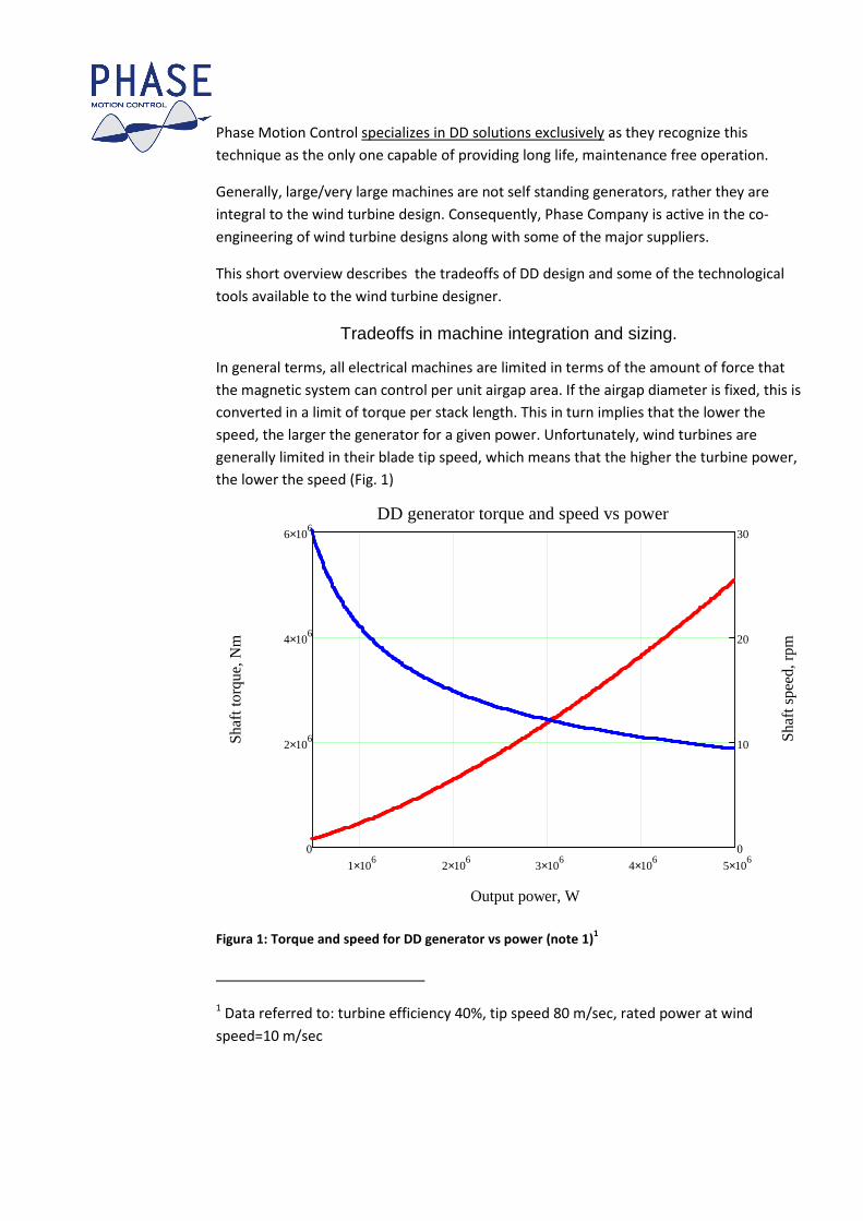
In general terms, all electrical machines are limited in terms of the amount of force that
the magnetic system can control per unit airgap area. If the airgap diameter is fixed, this is
converted in a limit of torque per stack length. This in turn implies that the lower the
speed, the larger the generator for a given power. Unfortunately, wind turbines are
generally limited in their blade tip speed, which means that the higher the turbine power,
the lower the speed (Fig. 1)
1 106× 2 10
6× 3 106× 4 10
6× 5 106×
0
2 106×
4 106×
6 106×
0
10
20
30
DD generator torque and speed vs power
Output power, W
Shaf
t tor
que,
Nm
Shaf
t spe
ed, r
pm
Figura 1: Torque and speed for DD generator vs power (note 1)1
1 Data referred to: turbine efficiency 40%, tip speed 80 m/sec, rated power at wind
speed=10 m/sec
Inspection of Fig 1 shows, for example, that the torque required, hence the size, of a 5
MW generator is not 5 times that of a 1 MW generator but over 11 times more due to the
lower operating speed, all other parameters being equal.
In order to optimize the performance, mass and cost of a DD generator Phase Motion
Control developed a number of special solutions in the magnetic circuit that improve the
available current density, magnet utilization factor, cooling and heat transfer, as well as
stray loss. These techniques allow a significant improvement in useable air gap thrust per
airgap surface area. Key parameters, however, depend on system choices that must be
shared with the overall turbine design.
In general terms, optimizing factors are the following:
1. Machine diameter
2. Airgap width selection, Bearing type and local deformation
3. Geometry (radial, double radial, axial, double axial, multi layer axial)
4. Cooling method
Machine diameter
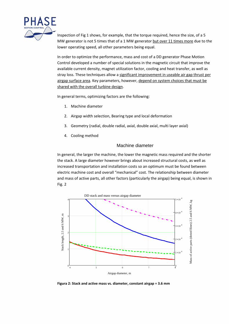
In general, the larger the machine, the lower the magnetic mass required and the shorter
the stack. A large diameter however brings about increased structural costs, as well as
increased transportation and installation costs so an optimum must be found between
electric machine cost and overall “mechanical” cost. The relationship between diameter
and mass of active parts, all other factors (particularly the airgap) being equal, is shown in
Fig. 2
4 5 6 7 80
1
2
3
4
0
1 104×
2 104×
3 104×
4 104×
5 104×
DD stack and mass versus airgap diameter
Airgap diameter, m
Stac
k le
ngth
, 2.5
and
6 M
W, m
Mas
s of
act
ive
part
s (d
otte
d lli
nes)
2.5
and
6 M
W, k
g
Figura 2: Stack and active mass vs. diameter, constant airgap = 3.6 mm
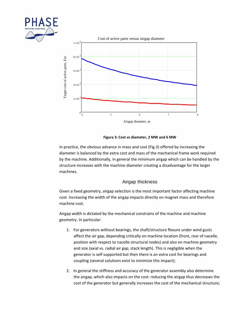
Figura 3: Cost vs diameter, 2 MW and 6 MW
In practice, the obvious advance in mass and cost (Fig.3) offered by increasing the
diameter is balanced by the extra cost and mass of the mechanical frame work required
by the machine. Additionally, in general the minimum airgap which can be handled by the
structure increases with the machine diameter creating a disadvantage for the larger
machines.
Airgap thickness
Given a fixed geometry, airgap selection is the most important factor affecting machine
cost. Increasing the width of the airgap impacts directly on magnet mass and therefore
machine cost.
Airgap width is dictated by the mechanical constrains of the machine and machine
geometry. In particular:
1. For generators without bearings, the shaft/structure flexure under wind gusts
affect the air gap, depending critically on machine location (front, rear of nacelle,
position with respect to nacelle structural nodes) and also on machine geometry
and size (axial vs. radial air gap, stack length). This is negligible when the
generator is self supported but then there is an extra cost for bearings and
coupling (several solutions exist to minimize this impact);
2. In general the stiffness and accuracy of the generator assembly also determine
the airgap, which also impacts on the cost: reducing the airgap thus decreases the
cost of the generator but generally increases the cost of the mechanical structure;
4 5 6 7 80
2 105×
4 105×
6 105×
8 105×
1 106×
Cost of active parts versus airgap diameter
Airgap diameter, m
Tar
get c
ost o
f ac
tive
part
s, E
ur
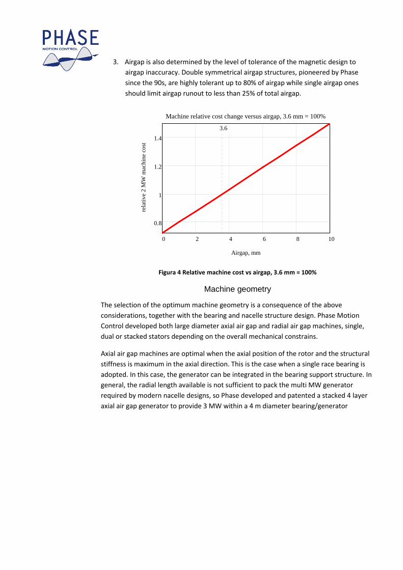
3. Airgap is also determined by the level of tolerance of the magnetic design to
airgap inaccuracy. Double symmetrical airgap structures, pioneered by Phase
since the 90s, are highly tolerant up to 80% of airgap while single airgap ones
should limit airgap runout to less than 25% of total airgap.
0 2 4 6 8 10
0.8
1
1.2
1.4
Machine relative cost change versus airgap, 3.6 mm = 100%
Airgap, mm
rela
tive
2 M
W m
achi
ne c
ost
3.6
Figura 4 Relative machine cost vs airgap, 3.6 mm = 100%
Machine geometry
The selection of the optimum machine geometry is a consequence of the above
considerations, together with the bearing and nacelle structure design. Phase Motion
Control developed both large diameter axial air gap and radial air gap machines, single,
dual or stacked stators depending on the overall mechanical constrains.
Axial air gap machines are optimal when the axial position of the rotor and the structural
stiffness is maximum in the axial direction. This is the case when a single race bearing is
adopted. In this case, the generator can be integrated in the bearing support structure. In
general, the radial length available is not sufficient to pack the multi MW generator
required by modern nacelle designs, so Phase developed and patented a stacked 4 layer
axial air gap generator to provide 3 MW within a 4 m diameter bearing/generator
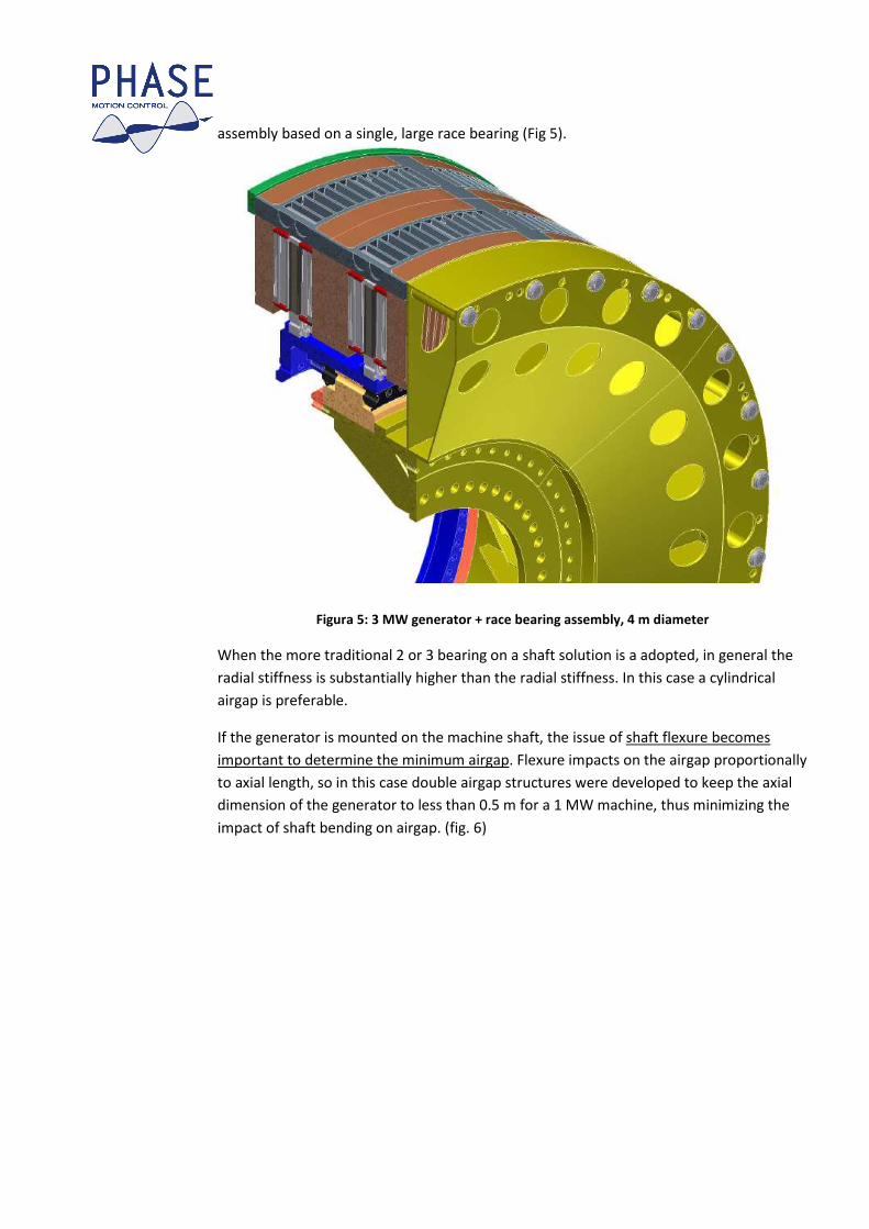
assembly based on a single, large race bearing (Fig 5).
Figura 5: 3 MW generator + race bearing assembly, 4 m diameter
When the more traditional 2 or 3 bearing on a shaft solution is a adopted, in general the
radial stiffness is substantially higher than the radial stiffness. In this case a cylindrical
airgap is preferable.
If the generator is mounted on the machine shaft, the issue of shaft flexure becomes
important to determine the minimum airgap. Flexure impacts on the airgap proportionally
to axial length, so in this case double airgap structures were developed to keep the axial
dimension of the generator to less than 0.5 m for a 1 MW machine, thus minimizing the
impact of shaft bending on airgap. (fig. 6)
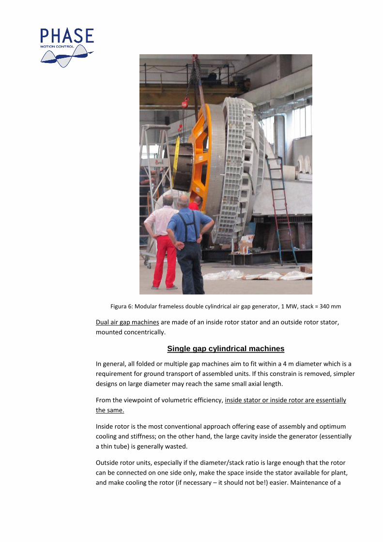
Figura 6: Modular frameless double cylindrical air gap generator, 1 MW, stack = 340 mm
Dual air gap machines are made of an inside rotor stator and an outside rotor stator,
mounted concentrically.
Single gap cylindrical machines
In general, all folded or multiple gap machines aim to fit within a 4 m diameter which is a
requirement for ground transport of assembled units. If this constrain is removed, simpler
designs on large diameter may reach the same small axial length.
From the viewpoint of volumetric efficiency, inside stator or inside rotor are essentially
the same.
Inside rotor is the most conventional approach offering ease of assembly and optimum
cooling and stiffness; on the other hand, the large cavity inside the generator (essentially
a thin tube) is generally wasted.
Outside rotor units, especially if the diameter/stack ratio is large enough that the rotor
can be connected on one side only, make the space inside the stator available for plant,
and make cooling the rotor (if necessary – it should not be!) easier. Maintenance of a
segmented modular structure is easier from inside the nacelle. On the other hand, they
tend to produce more acoustical noise than the inside rotor counterpart.
Cooling and protection.
Phase Motion Control pioneered the use of closed circuit water (or oil) cooling.
In the water cooling system, cooling water is fed through the generator cooling circuit,
possibly also through the same circuit in the converters, and then fed to a water-air
exchanger (essentially a radiator) which is generally placed in the wind outside of the
nacelle. No air is circulated inside the nacelle guaranteeing clean, maintenance free
operation. In general no fan is required on the radiator, as the cooling is required only
when wind is present, and the power used by the circulating pumps is a fraction of what
would be required by the fans typical of air cooled systems.
Water cooling allows higher power density than air cooling, reducing the cost of the
generator, but the main advantage is system reliability and environmental protection. This
is essential in difficult environments (offshore, desert) where filtering and filter cleaning is
either ineffective or impractical.
An additional system consideration is that the frequency converters also benefit greatly
from water cooling, and the current trend is towards this technology which offers great
advantages in term of power density and reliability. As an example, Phase is currently
manufacturing the AxW 400 A rated water cooled Dc-Ac converter with a
500x200x140mm footprint, and is developing the 1000 A, 800 V (.5MW) water cooled 12
phase converter AxW 1000 with a footprint of just 600x500x140mm. Air cooled converter
have a much larger physical size which also results in higher stray loss and lower
efficiency.
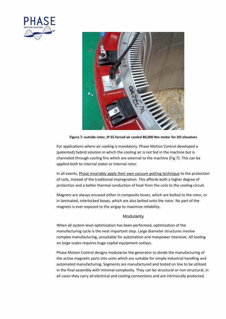
Figura 7: outside rotor, IP 65 forced air cooled 80,000 Nm motor for DD elevators
For applications where air cooling is mandatory, Phase Motion Control developed a
(patented) hybrid solution in which the cooling air is not fed in the machine but is
channeled through cooling fins which are external to the machine (Fig 7). This can be
applied both to internal stator or internal rotor.
In all events, Phase invariably apply their own vacuum potting technique to the protection
of coils, instead of the traditional impregnation. This affords both a higher degree of
protection and a better thermal conduction of heat from the coils to the cooling circuit.
Magnets are always encased either in composite boxes, which are bolted to the rotor, or
in laminated, interlocked boxes, which are also bolted onto the rotor. No part of the
magnets is ever exposed to the airgap to maximize reliability.
Modularity
When all system level optimization has been performed, optimization of the
manufacturing cycle is the next important step. Large diameter structures involve
complex manufacturing, unsuitable for automation and manpower intensive. All tooling
on large scales requires huge capital equipment outlays.
Phase Motion Control designs modularize the generator to divide the manufacturing of
the active magnetic parts into units which are suitable for simple industrial handling and
automated manufacturing. Segments are manufactured and tested on line to be utilized
in the final assembly with minimal complexity. They can be structural or non structural, in
all cases they carry all electrical and cooling connections and are intrinsically protected.
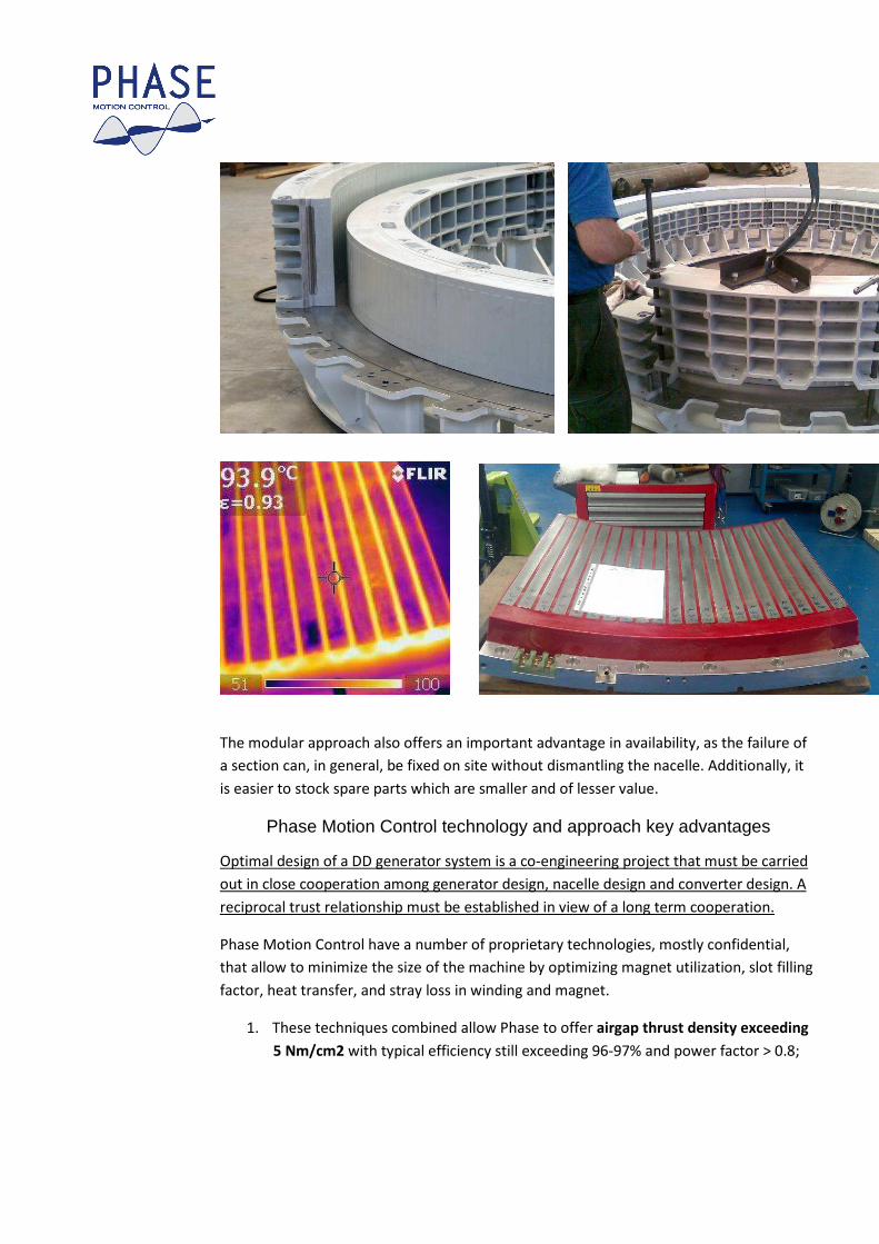
The modular approach also offers an important advantage in availability, as the failure of
a section can, in general, be fixed on site without dismantling the nacelle. Additionally, it
is easier to stock spare parts which are smaller and of lesser value.
Phase Motion Control technology and approach key advantages
Optimal design of a DD generator system is a co-engineering project that must be carried
out in close cooperation among generator design, nacelle design and converter design. A
reciprocal trust relationship must be established in view of a long term cooperation.
Phase Motion Control have a number of proprietary technologies, mostly confidential,
that allow to minimize the size of the machine by optimizing magnet utilization, slot filling
factor, heat transfer, and stray loss in winding and magnet.
1. These techniques combined allow Phase to offer airgap thrust density exceeding
5 Nm/cm2 with typical efficiency still exceeding 96-97% and power factor > 0.8;
2. Also, these results are achieved with relatively thin structures (less than 120 mm
combined rotor+stator magnetically active part) which provide about 40% mass
savings over comparable designs.
3. Phase is possibly the only Company to have extensive experience in the
development and supply of all geometries (cylindrical airgap, outside stator,
outside rotor, double symmetrical airgap; axial airgap, single and double side, all
modular, all multi meter diameter, air and water cooling) all in multi meter
diameter, all high energy PM, since almost 20 years; the VLT 10 m diameter drive
has been operational non stop since 1997.
All these techniques offer advantage over standard designs. These advantages, however,
are fully developed and maximized only in the framework of an integrated system design
in which mechanical constrains, assembly and transportation, as well as operational
requirements are optimized together. Phase are structured to offer just this type of co-
design.
In order to start a development program, Phase require some general information on the
constrains of the wind turbine design and the desired optimization space and weight
factors.
Initial information are:
1. Electrical power requirement: if a product family is in design, the family range and
the common parts which would be valuable to keep;
2. Turbine characteristics, torque, speed, overspeed; for a family range, same as
above;
3. Mechanical and interface constrains: whether a bearing choice was done already,
if the generator is bearing-less or fully supported; nacelle and shaft deformations,
manufacturing tolerances; A sketch of mechanical constrains and global
component arrangement would be most useful;
4. Assembly position and protection (inside or outside of nacelle?) IP rating;
5. Assembly and transportation constrains;
6. Environmental data, condensation, corrosion, cooling conditions;
7. Electronic interface: required DC bus voltage, number of sections, target of power
factor, half load efficiency, full load efficiency
8. Location and proximity of converters, wiring length;
9. Maximum short circuit torque allowed by the tower stiffness/resonance
10. Any items that are specific and desirable for the equipment manufacturer to
differentiate from the competition.
With these initial indications Phase can initiate a proposal.
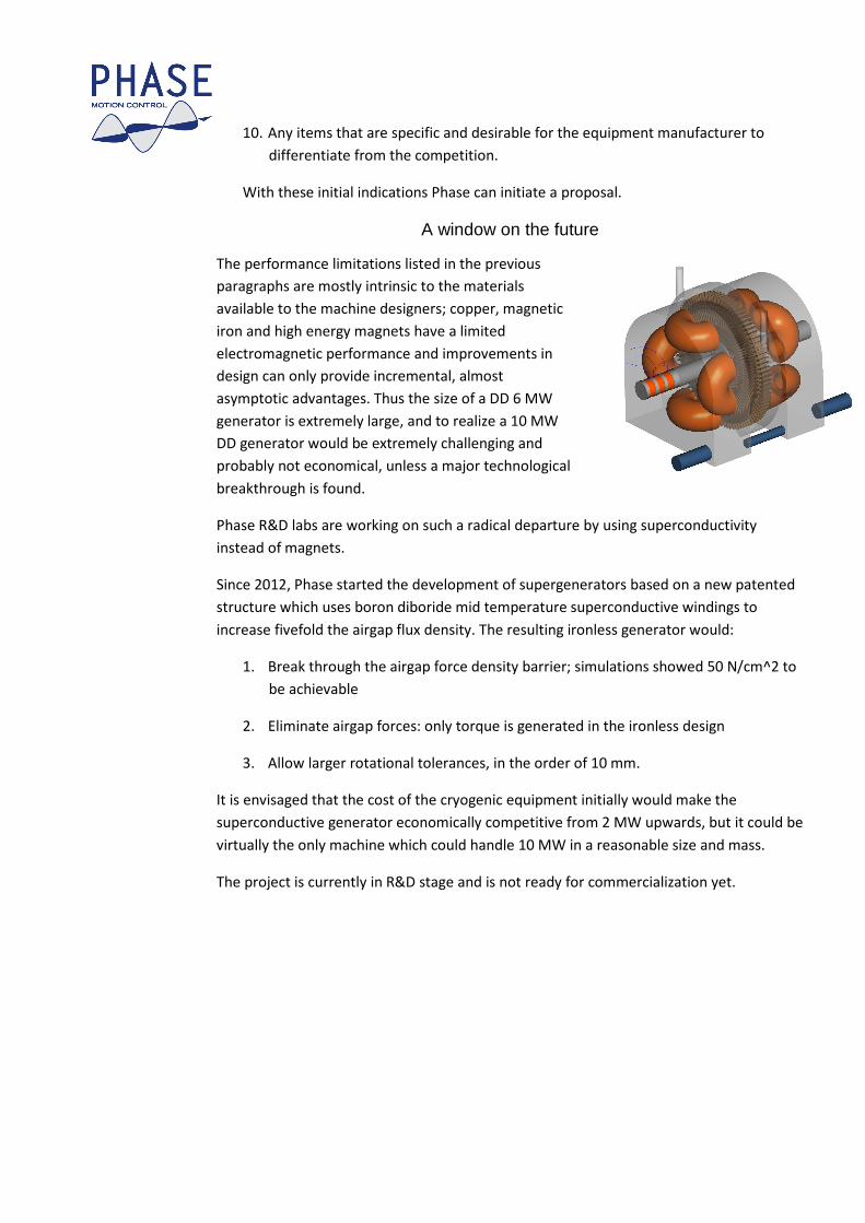
A window on the future
The performance limitations listed in the previous
paragraphs are mostly intrinsic to the materials
available to the machine designers; copper, magnetic
iron and high energy magnets have a limited
electromagnetic performance and improvements in
design can only provide incremental, almost
asymptotic advantages. Thus the size of a DD 6 MW
generator is extremely large, and to realize a 10 MW
DD generator would be extremely challenging and
probably not economical, unless a major technological
breakthrough is found.
Phase R&D labs are working on such a radical departure by using superconductivity
instead of magnets.
Since 2012, Phase started the development of supergenerators based on a new patented
structure which uses boron diboride mid temperature superconductive windings to
increase fivefold the airgap flux density. The resulting ironless generator would:
1. Break through the airgap force density barrier; simulations showed 50 N/cm^2 to
be achievable
2. Eliminate airgap forces: only torque is generated in the ironless design
3. Allow larger rotational tolerances, in the order of 10 mm.
It is envisaged that the cost of the cryogenic equipment initially would make the
superconductive generator economically competitive from 2 MW upwards, but it could be
virtually the only machine which could handle 10 MW in a reasonable size and mass.
The project is currently in R&D stage and is not ready for commercialization yet.
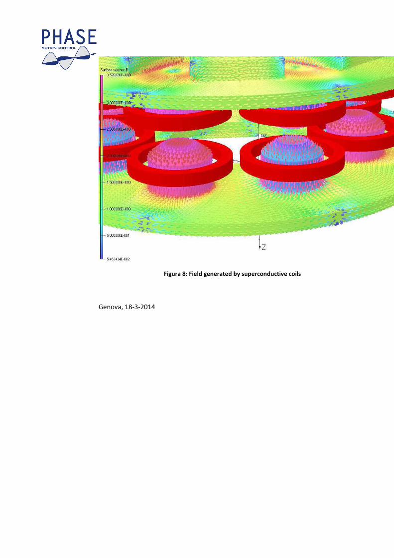
Figura 8: Field generated by superconductive coils
Genova, 18-3-2014


Reduction of Wind Induced Motion Utilizing a Tuned Sloshing Damper](https://img.pdfslide.us/doc/110x75/577d21d61a28ab4e1e960032/21990reduction-of-wind-induced-motion-utilizing-a-tuned-sloshing-damper.jpg)