Embed Size (px)
Citation preview

Phase I Final ReportNASA Institute for Advanced Concepts
A Realistic Interstellar Explorer
a. INSTITUTION:The Johns Hopkins UniversityApplied Physics Laboratory11100 Johns Hopkins Road, Laurel, MD 20723-6099
b. TITLE OF INVESTIGATION:A Realistic Interstellar Explorer
c1. PRINCIPAL INVESTIGATOR:Dr. Ralph L. McNutt, Jr.Voice: 443-778-5435Fax: [email protected]
c2. BUSINESS POINT OF CONTACT:Ms. Evelyn RyansVoice: 443-778-6156Fax: [email protected]
d. REPORTING MONTH:May 1999 - FINAL
e. IDENTIFICATION:NIAC CP 98-011998 PHASE I ADVANCED AERONAUTICAL/SPACE CONCEPT STUDIES
f. DATE OF SUBMISSION:31 May 1999
Table of Contents
1.0 Introduction___________________________________________________________________ 4
1.0.1 Advanced Concept Description__________________________________________________ 5
1.0.2 Science Rationale _____________________________________________________________ 7
1.0.3 Relevance to Office of Space Science Programs ____________________________________ 8
1.1 Mission Overview______________________________________________________________ 9
1.1.1 Mission Requirements _________________________________________________________ 9
1.1.2 Designing Fast, Low-Cost Trajectories to Four Solar Radii. ________________________ 11
1.1.3 Designing Trajectories from Perihelion to the Stars _______________________________ 12
1.1.4 Designing Reference Trajectories to 36 Ophiuchi and Epsilon Eridani________________ 13
1.1.4 Indirect Launch Mode ________________________________________________________ 14
1.2 Propulsion ___________________________________________________________________ 17
1.2.1 High Specific Impulse/High Thrust Concepts_____________________________________ 20
1.2.1.1 Orion and Nuclear Pulse Propulsion___________________________________________ 20
1.2.1.2 Solar Thermal Propulsion.___________________________________________________ 21
1.4 Thermal System_______________________________________________________________ 23
2. Interstellar Probe ______________________________________________________________ 26
2.1 General Probe Mission Aspects __________________________________________________ 26
2.1.1 Shakedown Cruise Period _____________________________________________________ 27
2.1.2 Prime Science Period _________________________________________________________ 28
2.2 System Configuration __________________________________________________________ 28
2.3 Structure ____________________________________________________________________ 29
2.4 Propulsion ___________________________________________________________________ 30
2.5 Power _______________________________________________________________________ 31
2.5.1 Primary Power – Battery Concept ______________________________________________ 31
2.5.2 Primary Power – ARPS concept________________________________________________ 31
2.5.3 Secondary Power ____________________________________________________________ 32
2.5.4 Power Regulation and Distribution _____________________________________________ 33
2.6 Guidance and Attitude Control __________________________________________________ 34
2.6.1 Trajectory and Clock Errors __________________________________________________ 35
2.6.2 Transmitter Boresight Pointing Knowledge ______________________________________ 35
2.6.3 Boresight Control____________________________________________________________ 35
2.7 Command and Data Handling ___________________________________________________ 36
2.7.1 Low Power Electronics _______________________________________________________ 38

2.7.2 Autonomous Operation _______________________________________________________ 39
2.7.2.1 Autonomy/Fault Tolerance/Safing ____________________________________________ 39
2.7.2.2 Sensor/Actuator/Communication (SAC) Module ________________________________ 41
2.7.2.3 Processes versus Processors __________________________________________________ 41
2.8 Communications ______________________________________________________________ 43
2.8.1 Microwave System ___________________________________________________________ 43
2.8.1.1 Microwave System Design ___________________________________________________ 44
2.8.1.2 Microwave Link Analysis____________________________________________________ 44
2.8.2 Optical System ______________________________________________________________ 44
2.8.2.1 Basic Optical Communications System Design __________________________________ 45
2.8.2.2 Optical System Requirements ________________________________________________ 46
2.8.2.3 Calculation of Probe Optical Power ___________________________________________ 48
2.9 Thermal System_______________________________________________________________ 49
2.10 Payload_____________________________________________________________________ 52
2.10.1 Magnetometer______________________________________________________________ 54
2.10.2 Plasma/Radio Wave Experiments _____________________________________________ 55
2.10.3 Neutrals, Plasma, and Suprathermal Dynamics and Composition___________________ 55
3. Extension of the Mission to Longer Durations_______________________________________ 56
4. Conclusions ___________________________________________________________________ 57
5. Acknowledgements _____________________________________________________________ 58
6. References____________________________________________________________________ 58
1.0 Introduction
For more than 20 years, an “Interstellar Precursor Mission” has been discussed as a highpriority for our understanding (1) the interstellar medium and its implications for the origin andevolution of matter in the Galaxy, (2) the structure of the heliosphere and its interaction with theinterstellar environment, and (3) fundamental astrophysical processes that can be sampled in situ.The chief difficulty with actually carrying out such a mission is the need for reaching significantpenetration into the interstellar medium (~1000 Astronomical Units (AU1)) within the workinglifetime of the initiators (<50 years). During the last two years there has been renewed interest inactually sending a probe to another star system - a "grand challenge" for NASA - and the idea ofa precursor mission has been renewed as a beginning step in a roadmap to achieve this goal.
Ongoing studies now being carried out by the Jet Propulsion Laboratory (JPL) in conjunctionwith a NASA-selected Interstellar Probe Science and Technology Definition Team (IPSTDT) arefocused on the use of solar sails to achieve a more modest goal of ~400 AU in 20 years with arequirement of reaching at least 200 AU. This approach, as well as all of those previouslyconsidered, obtains significant solar-system escape speeds by “dropping” the probe into the Sunand then executing a ∆V maneuver at perihelion. In the solar sail approach, the sail is used firstto remove the angular speed of the Earth and probe about the Sun; the sail is then maneuveredface-on into the Sun at 0.1 to 0.25 AU (set by sail thermal heating constraints), and solarradiation pressure accelerates the probe away from the Sun until the sail is jettisoned (at ~5 AUin the ongoing studies). The previous approaches, and that adopted for study here, initially sendthe probe out to Jupiter, using that planet's gravity to remove the probe angular momentum. Theprobe is then allowed to fall much closer to the Sun - in this case to 4 solar radii (RS
1) - where alarge propulsive ∆V maneuver is required over a very short time - taken here to be ~15 minutesto minimize gravity losses. At this time all acceleration is over and the probe continues on ahigh-energy ballistic escape trajectory from the solar system.
In the scenario studied in our Phase I work, the use of a carbon-carbon thermal shield and anexotic propulsion system capable of delivering high specific impulse (Isp) at high thrust isenabling. For the NASA/JPL case, the manufacture, deployment, and management of long-termlow-thrust maneuvering with a solar sail is the enabling propulsive technology. Bothimplementations require low-mass, highly integrated spacecraft in order to make use of moderate(Delta-class) expendable launch vehicles (ELVs). The further from the Sun that operation isrequired, the more stressing are the reliability requirements for the spacecraft itself. Our Phase Iconcept is baselined to operate at least 2.5 times as far from the Sun as the goal for the JPL study(1000 AU versus 400 AU) and contains system-architecture elements required as next-roadmap-step after the sail mission - our probe design is largely independent of the propulsion means,whether those studied previously by us, solar sails, or others. In the Phase I work we havecompleted an initial scoping of the system requirements and have identified system drivers foractually implementing such a mission.
In this Phase I study we began the task of looking seriously at the spacecraft mechanical,propulsion, and thermal constraints involved in escaping the solar system at high speed byexecuting a ∆V maneuver close to the Sun. In particular, to fully realize the potential of thisscenario, the required ∆V maneuver of ~10 to 15 km/s in the thermal environment of ~4 RS (fromthe center of the Sun) remains challenging. Two possible techniques for achieving high thrustlevels near the Sun are: (1) using solar heating of gas propellant, and (2) using a scaled-down
Orion (nuclear external combustion) approach. We investigated architectures that, combined withminiaturized avionics and miniaturized instruments, enable such a mission to be launched on avehicle with characteristics not exceeding those of a Delta III. This systems approach for such anInterstellar Explorer has not been previously used to address all of these relevant engineeringquestions but is required to lead to (1) a probe concept that can be implemented following asuccessful Solar Probe mission (concluding around 2010), and (2) system components andapproaches for autonomous operation of other deep-space probes within the solar system duringthe 2010 to 2050 time frame.
1.0.1 Advanced Concept Description
Two highly-ranked exploratory missions central to the discipline of Space Physics haveeluded the grasp of NASA and the Space Science community for over 20 years. The first, SolarProbe (SP), now slated for a 2007 launch, would explore the inner boundary of our stellarenvironment; the corona of the Sun. The second, the Interstellar Probe (IP), would probe theouter boundary: the Very Local Interstellar Medium (VLISM).
On a longer timescale there is the question of actually crossing the interstellar void itself. Inthis regard, IP is a precursor mission, i.e., it can answer fundamental science questions, assay ourlocal neighborhood for conditions through which a starship must travel, and, most significantly,act as a testbed for technologies that must be developed on our way to reaching the stars.
The problem is, of course, distance. It is a long way to the stars and compressing the time forthe journey into the scale of a human lifetime requires high speeds, and these, in turn, requirevery energetic means of propulsion [e.g., Forward, 1996]. The termination shock of the solarwind likely extends to ~100 AU while the loosely bound comets in the Oort cloud are thought topopulate a spherical region out to ~1 LY, so an Interstellar Probe must be able to make someinroad into this distance, even for a precursor mission.
The basic equation that governs spaceflight is the rocket equation. Relativistic correctionswere derived over 50 years ago [Ackeret, 1946; 1947], and these equations were soon applied tothe idea of interstellar travel. Acceleration of 1 Earth gravity (1g) for ~1 year suffices to bringthe vehicle to near light speed, producing significant time dilation. To attain high speedsefficiently, exhaust speeds also need to be near light speed; the large speeds required stilltranslate into large mass ratios, requiring in turn, large mass flow rates. These constraints, in turn,translate into the need for fusion or photon rockets [Shepherd, 1952; von Hoerner, 1962; Sänger,1961-2; Sagan, 1963; Forward, 1996].
To mitigate the phenomenal engineering challenges, suggestions have been made forlocating the source of energy elsewhere, e.g., for beaming power to the vehicle from the solarsystem, or fusing the material in the interstellar medium itself [Bussard, 1960; Forward, 1996,and references therein]. While some wishful thinking has looked to "post-quantum" physics foranswers (wormholes, reactionless drives, faster-than-light travel), today there is no evidence tosuggest that such schemes are more than wishful thinking.
If we are to take seriously the notion of interstellar travel toward the middle of the nextcentury, and try to plan to make it happen, then the best we can do is to rely on currently knownphysics, which can still push the limits of the doable even under the most optimistic oftechnological advances. A significant penetration of the VLISM would be ~10,000 AU in 50years. This requirement translates into a speed requirement of 200 AU/yr ³ 940 km-s-1 (exceedingthe escape speed from the Milky Way! [Allen, 1973]). An "optimized" rocket is characterized by
a mass ratio of exp(1.59) = 4.90 [von Hoerner, 1962], so such a rocket reaching 200 AU/yrrequires a specific impulse ~60,000 s. For a fusion rocket burning deuterium (D) and 3He (so thatthe exhaust can be directed by magnetic fields, e.g., Martin and Bond [1978]), the convertedmass fraction is 0.39%, and the effective exhaust speed is 26,450 km-s-1, corresponding to Isp ~2.7x10⁶ s. Worked the other way, such a D-3He rocket could attain 940 km-s-1 with a mass ratio of1.036.
Physically, such a system may be realizable, but given the current status of fusion research,there is no way to package such a propulsive system into several hundred kilograms or less, and aground-based test bed of a Daedalus-type system [Bond et al., 1978] is decades away. Hence, webelieve that realistically such a system is beyond the time frame of 10 to 40 years in the future,the time frame for this study. However, probes that can attain one-tenth this speed (and still attainthe same distance by traveling ten times as long) are, we believe, within grasp during this timeframe if the appropriate studies and thrusts are begun now.
In this Phase I work we examined carefully the mission requirements for an Interstellar Probeto (1) enable serious consideration of actually launching this mission before the middle of thenext century, and (2) minimize the required spacecraft mass and power, consistent with therequired science measurements (the "sciencecraft" paradigm), in order to minimize the launchvehicle requirements and, therefore, a major cost driver. The design will have multipleapplicabilities to outer solar system missions where mass will be at a premium, e.g., samplereturn missions from icy satellites or a Kuiper-belt object.
We have not discussed instrument packages in detail. These have been discussed and debatedmany times over; however, the proposed architecture is in consonance with current thinking andrequirements, and recently NASA's Interstellar Probe Science and Technology Definition Team(IPSTDT) has been examining the implementation of a more modest mission by making use ofsolar sail propulsion.
The work described here identifies a mission concept that can link the required science,desired instruments, spacecraft engineering and the realities of the fiscal and technological milieuin which NASA must operate if such missions are to reach fruition and lay the groundwork foreventually realizing true starships.
A "technically sweet" solution is to use the interstellar medium itself for fuel (the Bussard-ramjet approach, which still has problems with the magnetic intake [Forward, 1996]). TheInterstellar Probe proposed here would assay the content and clumpiness of the Very LocalInterstellar Medium (VLISM), assessing the possible implementation of a ramjet approach whilepioneering technologies required for long-term autonomous cruise. Such a precursor missioncould allow for the launch of such an advanced probe toward Epsilon Eridani or other stars latein the 21st century. At 200 AU/yr, such a second generation probe could make the first targetedinterstellar crossing in ~3500 years, the approximate duration of the Egyptian Empire A morerobust propulsion system that enabled a similar trajectory toward higher declination stars such asAlpha Centauri could make the corresponding shorter crossing in a correspondingly shorter timeof ~1400 years, the time that some buildings have been maintained, e.g., Hagia Sophia inConstantinople and the Pantheon in Rome. Though far from ideal, the stars would be within ourreach.
1.0.2 Science Rationale
Travel to the stars is the stuff that dreams and science fiction novels are made of. However,there is also a very scientifically compelling and serious side of the concept as well. A missionpast the boundary of the heliosphere to only a fraction of a light year would yield a rich scientificharvest [Jaffe and Ivie, 1979; Holzer et al., 1990].
The "fleet" of four interstellar spacecraft, Pioneer 10 and 11 and Voyager 1 and 2, all havespeeds in excess of the escape speed from the Sun and will penetrate into interstellar space.Powered by Radioisotope Thermoelectric Generators (RTGs), the spacecraft all have a finitelifetime due to the half life of the Pu-238 fuel (89 years) as well as degradation of the Si-Geconvertors in the RTGs. Pioneer 10 and 11 have effectively been "switched off" as they have runout of sufficient power for sustained operation. The Voyagers now form the Voyager InterstellarMission with the goal of at least penetrating the termination shock of the solar wind, which isthought to be located ~100 AU from the Sun.
Whether the Voyagers will actually reach the "undisturbed" interstellar medium prior tofalling silent as well remains unknown today. What is clear is that there are fundamentalsciencequestions that can only be addressed by instrumentation that actually penetrates outside ofthe heliosphere [Holzer et al., 1990; Mewaldt et al., 1995]. The science goals include:
Explore the nature of the interstellar medium and its implications for the origin andevolution of matter in the Galaxy. We know amazingly little about the nature of the Very LocalInterstellar Medium (VLISM). For example, measurements of rotation measures and dispersionmeasures of pulsars [Rand and Lyne, 1994] suggest a large scale magnetic field of ~1.4 µG, butwe have no idea of the structure or its variations within 0.1 or even 0.01 LY. Similarly, theproperties of the nonthermal portion of the medium (including the low-energy galactic cosmicrays) remain unknown.
Explore the structure of the heliosphere and its interaction with the interstellar medium.The Voyager Interstellar Mission may characterize the distance to the termination shock, but afarther-ranging probe is required to understand the dynamics of the interaction and how they areinfluenced by the conditions in the VLISM.
Explore fundamental astrophysical processes occurring in the heliosphere and theinterstellar medium. Shock acceleration of particles has profound impacts upon many sub-branches of astrophysics. In addition, the structure of the solar wind interface with the VLISMhas analogs in many other astrophysical settings.
Determine fundamental properties of the universe. Measurements of 3He, D, and 7Li wouldgive constraints on big-bang nucleosynthesis and on how these key indicators have beenprocessed in the interstellar medium [Schramm and Turner, 1998]. Also, by including anextremely accurate clock and a γ-ray detector, an extremely good baseline could be establishedfor constraining the location of gamma-ray bursts (GRBs) in the plane of the sky. Extremelyaccurate tracking of the IP can be used to look for gravitational waves and a non-zerocosmological constant. Polarization measurements of the downlink carrier can be used to look forinherent anisotropies in the structure of space [Nodland and Ralston, 1997]. If real, these couldbe related to new physics that might lead to faster travel times (fulfillment of the "wishfulthinking" mode of interstellar transport).
These science goals are all in accord with formulations being pursued by the Sun-EarthConnections Roadmap committee as part of the current NASA strategic planning exercise.
1.0.3 Relevance to Office of Space Science Programs
The idea of a dedicated interstellar “precursor” mission first surfaced at the conference“Missions Beyond the Solar System” held at the Jet Propulsion Laboratory (JPL) in August1976. The baseline mission was to reach 370 AU in 20 years after launch and 1030 AU in 50years after launch using a fission-based Nuclear Electric Propulsion (NEP) system [Jaffe andNorton, 1980; Jones and Sauer, 1984]. Key measurements were in situ measurements of thesolar wind, interaction region and the interstellar medium with the goal of characterizing nearinterstellar space [Jaffe and Ivie, 1979].
In March of 1990, the mission concept was revived [Holzer et al., 1990], as one of three“frontier probes,” to explore the global heliosphere and local interstellar space. Again the primefocus was in situ fields and particles measurements. The goal was scaled back to reaching ~200AU within ~25 years with 13 science instruments. A “powered solar flyby” was advocated as ameans of accomplishing a rapid escape from the solar system without requiring NEP. The 1990Workshop concept emphasis is in contrast with the TAU (Thousand AU) probe using a 1 MWNEP system to reach 1000 AU in ~50 yrs (terminal speed of 105 km-s-1) [Forward, 1996].
In the Space Physics Strategy-Implementation Study [1991] a “fields and particles”Interstellar Probe mission was endorsed and called out for a launch shortly after 2010 “to reach aminimum distance of 200 AU within 25 years. The main enabling technology problem wasviewed as the wedding of a large ÐV maneuver near the Sun (~4 RS - the distance proposed for anear-solar probe) or otherwise providing the high velocity required. The mission has also beenadvocated by both (1) the solar and space physics panel and (2) the astronomy and astrophysicspanel of the NAS/NRC study: Space Physics in the 21st Century - Imperatives for the Decades1995 to 2015, as well as previous NAS/NRC reports.
Most recently, in early 1999, NASA solicited membership in a committee to examineinterstellar probe requirements. This IPSTDT has had three meetings discussing the definition ofa science payload and its incorporation into a mission based upon a solar sail. In this case thesolar sail is the enabling technology but gives rise to similar instrumentation, power, andspacecraft requirements that are described here; results of the our work in the areas of spacecraftarchitecture, communication, and instrumentation accommodation are also applicable to thisother mission concept.
In our Phase I work we have (1) married the perihelion burn concept with advancedpropulsion concepts and studied packaging these in a realistic system architecture, (2) consideredthe science and engineering data that must be returned and used the requirements to design atelecommunications system that fits within spacecraft resources, (3) assembled a system design,subsystem by subsystem that can be launched on a Delta-III- class launch vehicle, and (4)investigated requirements for autonomous operations, reprogramming, and repairs. Our Phase Iresults have come a long way toward assembling such a self-consistent systems design.
To have a design that might fit the launch resources, we have set the probe mass to 50 kg;this has in turn decreased the payload mass (and power) and led us to an architecture that usescommon ultra-low power (ULP) processor modules. By relying on these, significant effort mustbe expended to move traditional hardware functions into software to conserve mass and supportan overall self-healing architecture. Although these cuts are drastic with respect to the initialdesign, they indicate the direction that the architecture and implementing technologies are drivenin order to implement this mission in this fashion.
1.1 Mission Overview
An interstellar precursor will only penetrate into the nearby interstellar medium. However,there are a variety of science goals to be accomplished, including taking the measure of the sizeof the heliosphere and investigating the properties of the undisturbed medium itself. The firstconstraint suggests that a mission should be sent near the "nose" of the heliosphere. This region,centered on the stagnation line in the flow of the ionized component of interstellar material as itinteracts with the solar wind, is the closest that the undisturbed interstellar medium comes to theSun. At the same time, there is general interest in exploring the properties of the medium, e.g., itsclumpiness, in the direction of nearby stars. By choosing a direction toward a nearby star, theprobe can report on conditions along its line of travel that is also in the direction along whichintegrated measurements can be made by employing the star's spectrum. For example, the Ly-aline profile yields information on both the hydrogen and deuterium column abundances betweenthe Sun and target star [Frisch, 1993; Linsky and Wood, 1996]. Targeting nearer stars can thusyield important information on the near (~few parsecs) interstellar medium. As the ultimate goalof the probe roadmap is a nearby Sun-like star, a K, G, or F star nearby is a good candidate.Finally, orbital mechanics constraints favor targets near the plane of the ecliptic (as discussedbelow). Taken together, these constraints have led us to baseline a mission toward EpsilonEridani (HD22049).
Epsilon Eridani is a K2V dwarf main sequence star 10.7 light years from Earth. The star wasused by Drake in his Project Ozma search for intelligent radio emissions (Tau Ceti was alsoobserved during the same time period in late 1960 [Sagan and Shklovskii, 1966]) and has beendebated as a possible site for an Earth-like planet [Lawton and Wright, 1990; Dole, 1964].Epsilon Eridani is nominally a single star but has a dust cloud surrounding it at a mean radius of~23 AU [Lawton and Wright, 1990]. The star also appears to have a hot corona similar to that ofthe Sun [Schmitt et al., 1996; Laming et al., 1996]. It has an apparent rotation period of 11.1 daysand may exhibit a magnetic activity cycle of ~5 years similar to the 11-year solar cycle; suchvariations are less pronounced in the other Sun-similar near stars τ Cet and σ Dra [Gray andBaliunas, 1995].
1.1.1 Mission Requirements
For this work, we adopt the use of a near-Sun ∆V maneuver to attain a high-speed escapefrom the solar system. This requires a Jupiter flyby to eliminate the heliocentric angularmomentum of the probe. Increased performance for a given launch vehicle is possible by usingan Earth flyby, but elimination of any Earth flybys is desirable for cutting down flight time withintensive operations, eliminating a deep-space burn, and eliminating the return of nuclearmaterials to the close proximity of Earth. It must be kept in mind that part of the increased throwmass must be used up in providing for a required deep-space maneuver, required to line up theprobe for the Earth gravity assist flyby.
For the baseline mission, we required that the probe should be launched with a Delta III-classlaunch vehicle and approach within four solar radii of the Sun. With no other constraints, energyand momentum conservation set the required injection energy (C
3) to effect the near-Sun passage.
The need to line up the outgoing asymptote of the trajectory toward the target direction while
having Jupiter in the correct position to effect the gravity assist means that the required planetaryalignment occurs roughly once every 13 years. The details of Jupiter's orbit cause the launchenergy requirements to change each launch window and return roughly to an optimum roughlyonce every 80 years for a launch toward ε Eridani.
The idea of using a high-Isp, high-thrust maneuver close to the Sun was first identified in 1929by rocket pioneer Hermann Oberth [Ehricke, 1972]. Measuring all speeds in km/s the asymptoticescape speed from the solar system is approximately
This equation gives an approximation to the required propulsive maneuver for a givenasymptotic speed. Note that for rp = 4 RS, the "crossover" point is roughly DV = vescape ~ 620 km-s-1 = 130 AU/yr. In other words, for escapes speeds below 130 AU/yr a perihelion maneuveroffers an advantage, providing that it can be implemented technically. Above this speed, there isno major advantage, and a direct departure outward from Earth's orbit offers the simplestimplementation.
As a baseline target we have chosen ∆V = 15 km-s-1 for the propulsion "target" to enable anasymptotic solar system escape speed of roughly 20 AU/yr. A 50-yr flight time will reach 1000AU, a distance well outside of the projected influence of the heliosphere/interstellar mediuminteraction region. A probe lifetime of 500 years will reach 10,000 AU, a significant penetrationinto local interstellar space.
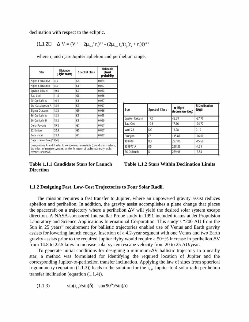
Candidate targets for solar system escape direction include the “nose” of our Sun’s helio-sphere, with J2000 heliocentric ecliptic right ascension of 74.9° and declination of -7.8°, as wellas nearby stars [Allen, 1973] with J2000 heliocentric declination within 33° of the ecliptic planethat are spectral types K, G, or F (near-Sun-like); Table 1.1.1 lists likely candidates for harboringEarth-like planets. The nearest stars [Section 114 of Allen, 1973] with Earth Mean Equator 1950declinations less than ±32.7° + 23.5° (Earth obliquity) comprised the initial candidate list. Thislist decreased after an Earth Mean Equator of 1950-to-Earth Mean Orbit (ecliptic) of 2000coordinate transformation indicated several stars with ecliptic declinations beyond ±32.7°. Theinitial screening of candidate stars (see Table 1.1.2) eliminated the potential of targeting well-known stars such as Alpha Centauri and Sirius, due to ecliptic declinations of -58.23° and -39.59°, respectively. The 32.7° limit comes from the turn angle (equation (1.1.1)) of animpulsive maneuver at a 4-solar radii perihelion (rp) that propels the spacecraft to a 20 AU/yearsolar system escape velocity (V•). This limiting case requires a 90°-inclination Jupiter-to-perihelion transfer, and assumes perihelion lies in the ecliptic plane.
ρ = cos-1(1/(1 + V 2rp/µSun)) where µSun = 2.9591221x10-04 AU3/day2 (1.1.1)
The ∆V required at perihelion (equation (1.1.2)) is the difference between the perihelionvelocities of the hyperbolic solar system escape and elliptic Jupiter-to-perihelion transfertrajectories. At a typical Jupiter-Sun range of 5 AU (approximate aphelion distance for theJupiter-to-perihelion transfer), a perihelion ∆V of 14.801 km/sec in the spacecraft velocitydirection will deliver the spacecraft to solar system escape conditions of 20 AU/year and ≤ 32.7°
vescape = ∆ V( )1
235 .147
rp
14
declination with respect to the ecliptic.
(1.1.2) ∆V = (V 2 + 2µSun
/ rp)0.5 - (2µ
Sun ra/(rp(ra + rp)))
0.5
where ra and rp are Jupiter aphelion and perihelion range.
ratS ecnatsiD)sraeYthgiL( )sraeYthgiL( )sraeYthgiL( )sraeYthgiL( )sraeYthgiL( ssalclartcepS
elbatibaHtenalp tenalp tenalp tenalp tenalp
ytilibaborp ytilibaborp ytilibaborp ytilibaborp ytilibaborp
AiruatneCahplA 3.4 4G 450.0
BiruatneCahplA 3.4 1K 750.0
inadirEnolispE 8.01 2K 330.0
iteCuaT 8.11 8G 630.0
AihcuihpO07 4.61 1K 750.0
AeaiepoissaCatE 0.81 9K 750.0
sinocarDamgiS 2.81 9G 630.0
AihcuihpO63 2.81 2K 320.0
BihcuihpO63 2.81 1K 020.0
sinovaPatleD 2.91 7G 750.0
inadirE28 9.02 5G 750.0
irdyHateB 3.12 1G 730.0
]4691[eloDmorfsiataD
;smetsysrats)dnuob(elpitlumnistnenopmocotreferBdnaAsnoitangiseDstibroyratenalpelbatsfonoitamrofehtnosmetsyselpitlumfotceffeeht
nwonknusniamer
ratS ssalClartcepS ααααα thgiR)ged(noisnecsA )ged(noisnecsA )ged(noisnecsA )ged(noisnecsA )ged(noisnecsA
δδδδδ noitanilceD)ged( )ged( )ged( )ged( )ged(
inadirEnolispE 2K 92.84 67.72-
iteCuaT 8G 66.71 77.42-
82floW GD 82.31 91.0
noycorP 5F 78.511 00.61-
804191 3K 60.792 86.51-
A779131 5K 62.822 13.4-
ihcuihpO63 1K 69.952 45.3-
Table 1.1.1 Candidate Stars for Launch Table 1.1.2 Stars Within Declination LimitsDirection
1.1.2 Designing Fast, Low-Cost Trajectories to Four Solar Radii.
The mission requires a fast transfer to Jupiter, where an unpowered gravity assist reducesaphelion and perihelion. In addition, the gravity assist accomplishes a plane change that placesthe spacecraft on a trajectory where a perihelion ∆V will yield the desired solar system escapedirection. A NASA-sponsored Interstellar Probe study in 1991 included teams at Jet PropulsionLaboratory and Science Applications International Corporation. This study’s “200 AU from theSun in 25 years” requirement for ballistic trajectories enabled use of Venus and Earth gravityassists for lowering launch energy. Insertion of a 4.2-year segment with one Venus and two Earthgravity assists prior to the required Jupiter flyby would require a 50+% increase in perihelion ∆Vfrom 14.8 to 22.5 km/s to increase solar system escape velocity from 20 to 25 AU/year.
To generate initial conditions for designing a minimum-∆V ballistic trajectory to a nearbystar, a method was formulated for identifying the required location of Jupiter and thecorresponding Jupiter-to-perihelion transfer inclination. Applying the law of sines from sphericaltrigonometry (equation (1.1.3)) leads to the solution for the iJ-S, Jupiter-to-4 solar radii periheliontransfer inclination (equation (1.1.4)).
(1.1.3) sin(iJ-S)/sin(δ) = sin(90)/sin(ρ)
where δ is target star declination - Table 1.1.2, ρ is the perihelion turn angle - eqn. (1.1.1)
(1.1.4) iJ-S = sin-1(sin(δ)/sin(ρ))
The corresponding heliocentric longitude of Jupiter, θJUP, in J2000 ecliptic coordinates is alsosolved with a spherical trigonometric relationship in equation (1.1.5).
(1.1.5) θJUP = α sin-1(tan(δ)/tan(iJ-S)), “+” for i J-S ≤ 90³´foriJ-S > 90
where α is the target star right ascension - see Table 1.1.2.For a given target star, solar system escape velocity (e.g., V = 20 AU/year), posigrade and
retrograde Jupiter-to-Sun transfers (iJ-S < 90° and iJ-S > 90°) and the corresponding heliocentriclongitude of Jupiter, two Jupiter encounter dates are determined per Jupiter orbit over the rangeof allowable Jupiter flybys (e.g., 2012-2042). The iterative solution procedure begins withfinding the Earth launch, Jupiter flyby, and subsequent perihelion dates that provide minimumlaunch energy, an unpowered Jupiter flyby, acceptable Jupiter flyby altitude, and minimummovement of the Jupiter flyby date from the initial θJUP-calculated date. Upon determination ofthis initial solution, the converged trajectory’s heliocentric longitude of Jupiter, θJUP is attainedfrom equation (1.1.5) by perturbing the propulsive turn angle at perihelion (ρ in eqn. (1.1.1)). Ifan increase in ρ yielded the updated θJUP, the solar system escape velocity, V , increases. Adecrease in ρ invalidated the solution, because V decreases below the 20 AU/year scienceconstraint. The new value of ρ yields a new value from equation (4) for ιJ-S, which is used toproduce a new converged Earth-Jupiter-perihelion trajectory. The revised Jupiter flyby dateproduces a new θJUP, and the iteration process continues until established convergence criteria(e.g., Jupiter flyby date changes less than 0.1 days from the previous iteration) are met.
1.1.3 Designing Trajectories from Perihelion to the Stars
The ∆V from equation (1.1.2) is updated using the final V and ra (approximated by Jupiter’sdistance to the Sun at Jupiter flyby). This ∆V is applied in the spacecraft velocity direction to theperihelion spacecraft state vector. Propagation of the resulting solar system escape trajectory to1000 AU delivers the spacecraft to the target star direction. An angle offset of less than theperihelion latitude in declination and still less in right ascension from the target star directionoccurs with this method. Most of the offset is explained by the off-normal-to-the-eclipticcomponents of the perihelion ∆V. Precision targeting of target star was then achieved by liftingthe “velocity direction only” constraint at perihelion. The resulting ∆V penalty is then assessed inmagnitude and spacecraft orientation offset from thrusting in the velocity direction. The affectsof finite burn and maximum permissible thrust acceleration have not been considered at thispoint.
1.1.4 Designing Reference Trajectories to 36 Ophiuchi and Epsilon Eridani
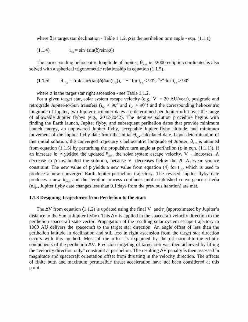
A 2019 launch to 36 Ophiuchi represents the lowest launch energy (C3 = 100.6 km2/s2) casefor a ~20 AU/year trajectory to a star listed in Table 1.1.1. For this launch energy maximumpayloads are 425 kg for a 3-stage Delta III (Star 48 upper stage) and 500 kg for an AtlasIIAS/Star 48. This trajectory passes within 799,000 km of Jupiter at 21.519 km/s (12.078 km/sexcess velocity) with a 27.0° approach phase angle. The Jupiter flyby lowers perihelion from0.99 AU to 0.02 AU, lowers aphelion from 8.74 AU to 5.16 AU, and increases orbital inclinationin order to provide proper orientation for the perihelion burn. Two years later, a 15.958 km/sperihelion ∆V within 8.8° of the spacecraft velocity direction directs the spacecraft towards 36Ophiuchi at 20.7 AU/year.
A 2011 launch to Epsilon Eridani represents a low launch energy (C3 = 117.1 km2/s2) case toa star situated near (within 32.1°) the direction from the Sun to the heliosphere “nose.” For thislaunch energy maximum payloads are 256 kg for a 3-stage Delta III and 342 kg for an AtlasIIAS/Star 48. This trajectory, summarized in Table 1.1.3 and depicted in Figure 1.1.1, passeswithin 653,300 km of Jupiter at 23.527 km/s (12.868 km/s excess velocity) with a 24.7°approach phase angle. The Jupiter flyby lowers perihelion from 1.02 AU to 0.02 AU, lowersaphelion from 11.88 AU to 5.05 AU, and increases orbital inclination in order to provide properorientation for the perihelion burn. Two years later, a 15.393 km/s perihelion ∆V 12.5° from thespacecraft velocity direction sends the spacecraft toward Epsilon Eridani at 20.2 AU/year.
tnevE etaDnuS
ecnatsid ecnatsid ecnatsid ecnatsid ecnatsid)UA( )UA( )UA( )UA( )UA(
noitanilcnI)ged( )ged( )ged( )ged( )ged(
citpilcEnoitatneiro noitatneiro noitatneiro noitatneiro noitatneiro
taL noL
ihcuihpO63ddawoT ihcuihpO63ddawoT ihcuihpO63ddawoT ihcuihpO63ddawoT ihcuihpO63ddawoThcnuaL 809.81beF9102 4889.0 0.22-=ALD 100.0- 686.941
retipuJybylf 659.13luJ0202 6051.5 5.0 492.0- 925.392
noilehireP 857.13luJ2202 6810.0 4.6 813.0 513.311
UA0001 645.9voN0702 0000.0001 5.3 045.3- 069.952
drawoT drawoT drawoT drawoT drawoT εεεεε inadirE inadirE inadirE inadirE inadirEhcnuaL 081.21luJ1102 6610.1 9.3=ALD 100.0 053.982
retipuJybylf 650.62tcO2102 3440.5 1.1 507.0- 127.76
noilehireP 420.82voN4102 6810.0 7.75 835.0 728.742
UA0001 905.13yaM4602 0000.0001 67.72 067.72- 092.84
Table 1.1.3 Key Events for Sample Figure 1.1.1 Ecliptic Plane Projection ofMissions Instellar Probe Trajectory toward e Eridani
1.1.4 Indirect Launch Mode
The ε Eridani trajectory is of some interest for reasons already mentioned. However, therelatively large C3 and use of the Delta III severely constrains the available payload mass. Toincrease the available throw weight, we consider the use of the indirect launch mode [Farquharand Dunham, 1999].
To provide more throw weight and flexibility in the launch window, an additional stage canbe incorporated into the spacecraft. Typically, the spent stage is retained to minimize thecomplexity of the structural design, but with the additional thermal and propulsion constraintsthat the probe faces during the perihelion maneuver, provision needs to be made to jettison thisupper, upper stage subsequent to its firing.
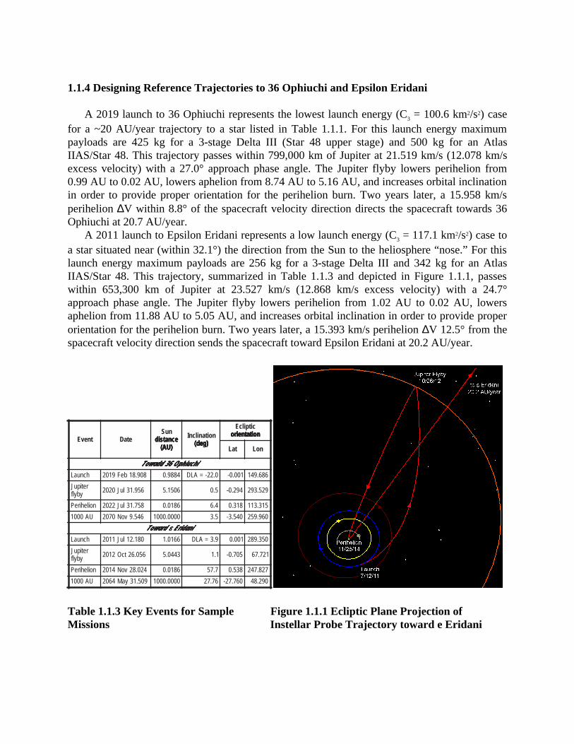
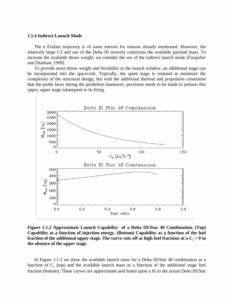
Figure 1.1.2 Approximate Launch Capability of a Delta III/Star 48 Combination. (Top)Capability as a function of injection energy. (Bottom) Capability as a function of the fuelfraction of the additional upper stage. The curve cuts off at high fuel fractions at a C3 = 0 inthe absence of the upper stage.
In Figure 1.1.2 we show the available launch mass for a Delta III/Star 48 combination as afunction of C3 (top) and the available launch mass as a function of the additional stage fuelfraction (bottom). These curves are approximate and based upon a fit to the actual Delta III/Star
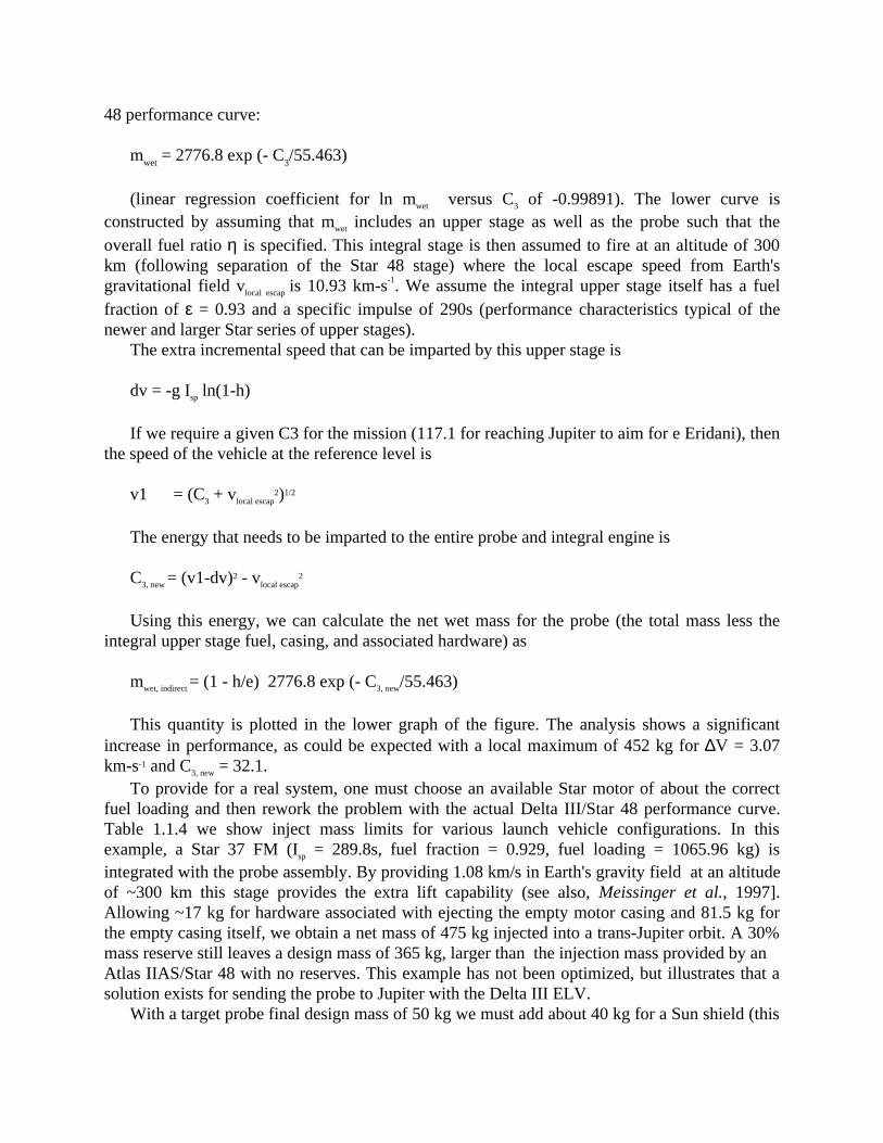
48 performance curve:
mwet = 2776.8 exp (- C3/55.463)
(linear regression coefficient for ln mwet versus C3 of -0.99891). The lower curve isconstructed by assuming that mwet includes an upper stage as well as the probe such that theoverall fuel ratio η is specified. This integral stage is then assumed to fire at an altitude of 300km (following separation of the Star 48 stage) where the local escape speed from Earth'sgravitational field vlocal escap is 10.93 km-s-1. We assume the integral upper stage itself has a fuelfraction of ε = 0.93 and a specific impulse of 290s (performance characteristics typical of thenewer and larger Star series of upper stages).
The extra incremental speed that can be imparted by this upper stage is
dv = -g Isp ln(1-h)
If we require a given C3 for the mission (117.1 for reaching Jupiter to aim for e Eridani), thenthe speed of the vehicle at the reference level is
v1 = (C3 + vlocal escap2)1/2
The energy that needs to be imparted to the entire probe and integral engine is
C3, new = (v1-dv)2 - vlocal escap2
Using this energy, we can calculate the net wet mass for the probe (the total mass less theintegral upper stage fuel, casing, and associated hardware) as
mwet, indirect = (1 - h/e) 2776.8 exp (- C3, new/55.463)
This quantity is plotted in the lower graph of the figure. The analysis shows a significantincrease in performance, as could be expected with a local maximum of 452 kg for ∆V = 3.07km-s-1 and C3, new = 32.1.
To provide for a real system, one must choose an available Star motor of about the correctfuel loading and then rework the problem with the actual Delta III/Star 48 performance curve.Table 1.1.4 we show inject mass limits for various launch vehicle configurations. In thisexample, a Star 37 FM (Isp = 289.8s, fuel fraction = 0.929, fuel loading = 1065.96 kg) isintegrated with the probe assembly. By providing 1.08 km/s in Earth's gravity field at an altitudeof ~300 km this stage provides the extra lift capability (see also, Meissinger et al., 1997].Allowing ~17 kg for hardware associated with ejecting the empty motor casing and 81.5 kg forthe empty casing itself, we obtain a net mass of 475 kg injected into a trans-Jupiter orbit. A 30%mass reserve still leaves a design mass of 365 kg, larger than the injection mass provided by anAtlas IIAS/Star 48 with no reserves. This example has not been optimized, but illustrates that asolution exists for sending the probe to Jupiter with the Delta III ELV.
With a target probe final design mass of 50 kg we must add about 40 kg for a Sun shield (this
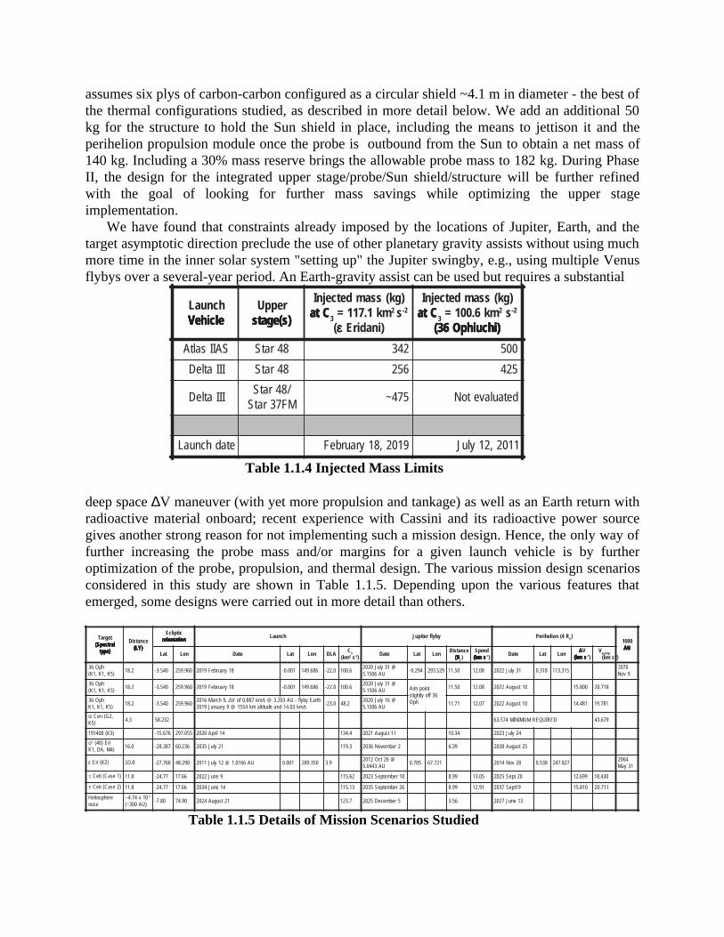
assumes six plys of carbon-carbon configured as a circular shield ~4.1 m in diameter - the best ofthe thermal configurations studied, as described in more detail below. We add an additional 50kg for the structure to hold the Sun shield in place, including the means to jettison it and theperihelion propulsion module once the probe is outbound from the Sun to obtain a net mass of140 kg. Including a 30% mass reserve brings the allowable probe mass to 182 kg. During PhaseII, the design for the integrated upper stage/probe/Sun shield/structure will be further refinedwith the goal of looking for further mass savings while optimizing the upper stageimplementation.
We have found that constraints already imposed by the locations of Jupiter, Earth, and thetarget asymptotic direction preclude the use of other planetary gravity assists without using muchmore time in the inner solar system "setting up" the Jupiter swingby, e.g., using multiple Venusflybys over a several-year period. An Earth-gravity assist can be used but requires a substantial
hcnuaLelciheV elciheV elciheV elciheV elciheV
reppU)s(egats )s(egats )s(egats )s(egats )s(egats
)gk(ssamdetcejnICta Cta Cta Cta Cta 3 mk1.711= 2 s 2-
(εεεεε )inadirE
)gk(ssamdetcejnICta Cta Cta Cta Cta 3 mk6.001= 2 s 2-
)ihcuihpO63( )ihcuihpO63( )ihcuihpO63( )ihcuihpO63( )ihcuihpO63(
SAIIsaltA 84ratS 243 005
IIIatleD 84ratS 652 524
IIIatleD/84ratSMF73ratS
574~ detaulavetoN
etadhcnuaL 9102,81yraurbeF 1102,21yluJ
Table 1.1.4 Injected Mass Limits
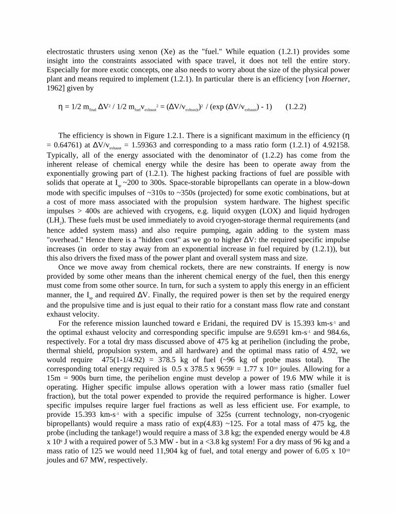
deep space ∆V maneuver (with yet more propulsion and tankage) as well as an Earth return withradioactive material onboard; recent experience with Cassini and its radioactive power sourcegives another strong reason for not implementing such a mission design. Hence, the only way offurther increasing the probe mass and/or margins for a given launch vehicle is by furtheroptimization of the probe, propulsion, and thermal design. The various mission design scenariosconsidered in this study are shown in Table 1.1.5. Depending upon the various features thatemerged, some designs were carried out in more detail than others.
tegraTlartcepS( lartcepS( lartcepS( lartcepS( lartcepS(
)epyt )epyt )epyt )epyt )epyt
ecnatsiD)YL( )YL( )YL( )YL( )YL(
citpilcEnoitatneiro noitatneiro noitatneiro noitatneiro noitatneiro
hcnuaL ybylfretipuJ R4(noilehireP S)0001
UAUAUAUAUAtaL noL etaD taL noL ALD
C3mk( 2 s 2- )
etaD taL noLecnatsiD
R(R(R(R(R( J)deepS
smk( smk( smk( smk( smk( 1- )etaD taL noL
∆∆∆∆∆Vsmk( smk( smk( smk( smk( 1- )
V pmysasmk( 1- )
hpO63)5K,1K,1K(
2.81 045.3- 069.952 81yraurbeF9102 100.0- 686.941 0.22- 6.001@13yluJ0202
UA6051.5492.0- 925.392 05.11 80.21 13yluJ2202 813.0 513.311
07029voN
hpO63)5K,1K,1K(
2.81 045.3- 069.952 81yraurbeF9102 100.0- 686.941 0.22- 6.001@13yluJ0202
UA6051.5 tniopmiA63ffoylthgils
hpO
05.11 80.21 01tsuguA2202 008.51 817.02
hpO63)5K,1K,1K
2.81 045.3- 069.952,9hcraM6102 ∆ htraEybylf-UA302.3@s/mk788.0foV
s/[email protected] 2.84
@61yluJ0202UA6051.5
17.11 70.21 01tsuguA2202 184.41 187.91
α ,2G(neC)5K 3.4 232.85 DERIUQERMUMINIM475.36 976.34
)3K(804191 676.51- 550.792 41lirpA0202 4.431 11tsuguA1202 43.01 42yluJ3202
ο2 irE)04()4M,AD,1K 0.61 783.82- 632.06 12yluJ5302 3.911 2rebmevoN6302 93.6 52tsuguA8302
ε )2K(irE 8.01 067.72- 092.84 UA6610.1@21yluJ1102 100.0 053.982 9.3@62tcO2102
UA3440.5507.0 127.76 82voN4102 835.0 728.742
460213yaM
τ )1esaC(iteC 8.11 77.42- 66.71 9enuJ2202 26.511 81rebmetpeS3202 99.8 50.31 02tpeS5202 996.21 034.81
τ )2esaC(iteC 8.11 77.42- 66.71 41enuJ4302 31.511 62rebmetpeS5302 99.8 19.21 91tpeS7302 018.51 117.02
erehpsoileHeson
01x47.4~ 3-
)UA003~(08.7- 09.47 12tsuguA4202 7.321 5rebmeceD5202 65.3 31enuJ7202
Table 1.1.5 Details of Mission Scenarios Studied
1.2 Propulsion
The basic equation that governs spaceflight is the rocket equation:
minitial/mfinal= exp (∆V/I spg) (1.2.1)
∆V is the change in speed, Isp is the specific impulse (Ispg is the exhaust speed), and minitial andmfinal are the original mass and the mass following the speed change, respectively. Relativisticcorrections were derived over 50 years ago [Ackeret, 1946], and these equations were soonapplied to the idea of interstellar travel. Acceleration of 1 Earth gravity (1g) for ~1 year suffices
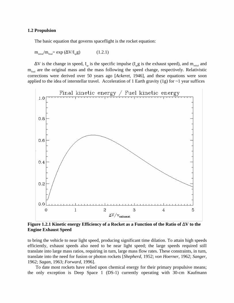
Figure 1.2.1 Kinetic energy Efficiency of a Rocket as a Function of the Ratio of ∆V to theEngine Exhaust Speed
to bring the vehicle to near light speed, producing significant time dilation. To attain high speedsefficiently, exhaust speeds also need to be near light speed; the large speeds required stilltranslate into large mass ratios, requiring in turn, large mass flow rates. These constraints, in turn,translate into the need for fusion or photon rockets [Shepherd, 1952; von Hoerner, 1962; Sanger,1962; Sagan, 1963; Forward, 1996].
To date most rockets have relied upon chemical energy for their primary propulsive means;the only exception is Deep Space 1 (DS-1) currently operating with 30-cm Kaufmann
electrostatic thrusters using xenon (Xe) as the "fuel." While equation (1.2.1) provides someinsight into the constraints associated with space travel, it does not tell the entire story.Especially for more exotic concepts, one also needs to worry about the size of the physical powerplant and means required to implement (1.2.1). In particular there is an efficiency [von Hoerner,1962] given by
η = 1/2 mfinal ∆V2 / 1/2 mfuelvexhaust2 = (∆V/vexhsus)t)2 / (exp (∆V/vexhaust) - 1) (1.2.2)
The efficiency is shown in Figure 1.2.1. There is a significant maximum in the efficiency (η= 0.64761) at ∆V/vexhaust = 1.59363 and corresponding to a mass ratio form (1.2.1) of 4.92158.Typically, all of the energy associated with the denominator of (1.2.2) has come from theinherent release of chemical energy while the desire has been to operate away from theexponentially growing part of (1.2.1). The highest packing fractions of fuel are possible withsolids that operate at Isp ~200 to 300s. Space-storable bipropellants can operate in a blow-downmode with specific impulses of ~310s to ~350s (projected) for some exotic combinations, but ata cost of more mass associated with the propulsion system hardware. The highest specificimpulses > 400s are achieved with cryogens, e.g. liquid oxygen (LOX) and liquid hydrogen(LH2). These fuels must be used immediately to avoid cryogen-storage thermal requirements (andhence added system mass) and also require pumping, again adding to the system mass"overhead." Hence there is a "hidden cost" as we go to higher ∆V: the required specific impulseincreases (in order to stay away from an exponential increase in fuel required by (1.2.1)), butthis also drivers the fixed mass of the power plant and overall system mass and size.
Once we move away from chemical rockets, there are new constraints. If energy is nowprovided by some other means than the inherent chemical energy of the fuel, then this energymust come from some other source. In turn, for such a system to apply this energy in an efficientmanner, the Isp and required ∆V. Finally, the required power is then set by the required energyand the propulsive time and is just equal to their ratio for a constant mass flow rate and constantexhaust velocity.
For the reference mission launched toward e Eridani, the required DV is 15.393 km-s-1 andthe optimal exhaust velocity and corresponding specific impulse are 9.6591 km-s-1 and 984.6s,respectively. For a total dry mass discussed above of 475 kg at perihelion (including the probe,thermal shield, propulsion system, and all hardware) and the optimal mass ratio of 4.92, wewould require 475(1-1/4.92) = 378.5 kg of fuel (~96 kg of probe mass total). Thecorresponding total energy required is 0.5 x 378.5 x 96592 = 1.77 x 10¹⁰ joules. Allowing for a15m = 900s burn time, the perihelion engine must develop a power of 19.6 MW while it isoperating. Higher specific impulse allows operation with a lower mass ratio (smaller fuelfraction), but the total power expended to provide the required performance is higher. Lowerspecific impulses require larger fuel fractions as well as less efficient use. For example, toprovide 15.393 km-s-1 with a specific impulse of 325s (current technology, non-cryogenicbipropellants) would require a mass ratio of exp(4.83) ~125. For a total mass of 475 kg, theprobe (including the tankage!) would require a mass of 3.8 kg; the expended energy would be 4.8x 10⁹ J with a required power of 5.3 MW - but in a <3.8 kg system! For a dry mass of 96 kg and amass ratio of 125 we would need 11,904 kg of fuel, and total energy and power of 6.05 x 10¹⁰
joules and 67 MW, respectively.
It is worth mentioning that very high Isp ion thrusters are also very inefficient in their powerconsumption if the ion exhaust speed is >> the ∆V required.
Chemical production of such high specific impulses is not possible; such large ∆Vs are onlyattainable with large amounts of fuel and staging, e.g. the 19.7-metric ton IUS/PAM-Dcombination required to boost the 360-kg Ulysses spacecraft by 15.4 km-s-1. The only othermeans of propulsion that do not rely on exotic - and currently unfounded - physics use eithernuclear energy produced on board the spacecraft or energy beamed to the spacecraft, the latterincluding the use of sunlight for Solar Electric Propulsion (SEP), solar sail propulsion, and lasersor microwaves for beamed energy propulsion. The use of microwaves as a propulsive force hasbeen discussed by Forward [1996] and the use of lasers is incorporated in the sail technologyroadmap as a follow on to solar sail propulsion [Wallace, 1998]. These beamed-energy schemesrequire large power-production infrastructures, albeit on the "ground" and are beyond the scopeof our current work, As noted previously, solar-sail propulsion is currently under study for anear-term interstellar precursor mission with a candidate launch date of ~June 2010.
SEP is now being demonstrated with DS-1. The utility of SEP is limited by the mass of thesolar arrays, ion thrusters, and power processing units, currently ~65kg/kW. Ion thrusters havealso been considered for implementation in Nuclear Electric Propulsion (NEP) schemes that relyupon nuclear (fission) reactors for providing power. However, such systems are heavy, theaborted Nuclear Electric Propulsion Space Test Program (NEPSTP) baselined a variety ofthrusters and a then-Soviet TOPAZ II nuclear reactor. The reactor provided ~6 kW of power witha 1000 kg reactor mass (~167 kg/kW). The spacecraft had a wet mass of 3500 kg, including 700kg of Xe fuel [Mauk et al., 1993]. The program was cancelled due to changing national prioritiesand budgetary pressures. The SP-100 Flight Experiment had, at one time, baselined a 93 kWammonia arcjet system with a reactor specific mass of 30 kg/kW. The system would run at an Isp
~1000s and a mass flow rate of ~0.25 g/s [Deininger and Vondra, 1991]. This system hasremained a concept only to date. The baseline design discussed
Pure ion engines are limited by the space-charge within the engine chamber. Allowablecurrent densities are given by the Child-Langmuir relation; minimal spacing between electrodesis set by field emission of electrons if the electric field is increased to too large a value. Forexample the NASA SEP Technology Readiness Application Readiness (NSTAR) program usesXe ions and runs at a specific impulse of 1990s at minimum power and 3280s at maximumpower. Corresponding mass flow rates vary from ~0.94 milligram/s to ~2.55 milligram/s. About8000 hours is required to use ~83 kg of propellant; this also corresponds to the engine lifetimesusing current technology [Williams and Coverstone-Carroll, 1997]. These low thrust rates are setby the inherent physics of the space-charge within the engines, so significant increases in themass flow rates do not seem likely. The use of radioisotope electric propulsion has also beendiscussed; current specific masses are ~200 kg/kW but could possibly be decreased by a factor of~4 with technology development [Noble, 1996].
All of these concepts relying on electric thrust and solar- or nuclear-derived electrical powersuffer from mass flow rates that are too small by orders of magnitude to meet the perihelionthrust requirement. Although the direct use of nuclear reactions is a well-known (and well-studied!) subject, [Cassenti, 1996] typical system sizes are driven to large values byconsiderations of the means of applying the energy source to propulsion.
1.2.1 High Specific Impulse/High Thrust Concepts
We have considered two concepts in some detail to identify a means of applying the ~15km-s-1 ∆V required at solar perihelion: (1) an Orion-type nuclear drive and (2) solar thermalpropulsion. In comparison with sail, SEP, and NEP, the requirement is to provide a high thrustfor a brief period of time similar to conventional rockets and upper stages, but, significantly, at aspecific impulse about 3.5 times larger, i.e. at Isp~1000s.
1.2.1.1 Orion and Nuclear Pulse Propulsion
The Orion project took place during the late 1950's through the early 1960's to attempt todesign a practical rocket relying upon nuclear fission explosions to drive a rocket. At face valuenuclear explosions easily contain sufficient energy to power the propulsion system: The energyrelease in the explosion of TNT is ~4 x 10¹⁰ erg/g while that in fission is ~7 x 10¹⁷ erg/g (1 kiloton- kT - is typically taken as 1012 calories, and 1 kg of totally fissioned uranium can release ~10kT, Serber [1992]). Hence for the ideal case mentioned previously, with ~2 x 10¹⁰ joulesrequired, we need the fission energy of ~0.5 g of uranium - a total of about 5 tons of TNTequivalent.
The problem with such systems is the coupling of the momentum into the ship over shorttime scales ~10-8 s. Transferring significant amounts of impulse to a structure over such shorttimes typically causes stress to exceed the yield strengths of all known materials [Dyson, 1965;1968]. The Orion concept [Boyer and Balcomb, 1971] and its derivatives [Solem, 1993; 1994]require large masses for dealing with the release of ~1 to 10 kT explosions. The alternative is togo to much smaller explosive yields and pulse the system. Ideas adapted from inertialconfinement fusion with yields ~0.01 kT have been adapted to a variety of systems studies;however, the spacecraft masses again tend to be large due to the power plant overhead, here thelaser system, required to initiate the microexplosions [Hyde et al., 1972].
Small yields are possible (and termed "fizzles" [cf. Chapter 18 of Winterberg, 1981; Chapter17 of Serber, 1992]), although still in yields of 10s of tons for a typical weapon configuration.Here the problem is that although very little fission energy is needed per pulse, a minimum massis still required in order for criticality, in turn needed to provide neutron multiplication forsufficient energy to be generated in a microexplosion (about 20 doublings as compared with ~58in a weapon [Serber, 1992]). The actual yield can be reduced by using tampers, but only at theexpense of mass. Whether a workable system based upon fission microexplosions can beimplemented at a low system mass is still questionable, but worth pursuing. The real question iswhether appropriate geometries can be assembled and initiated, e.g., using a DT neutron sourcethat uses a small (~120 keV) linear accelerator to produce fast neutrons. Here the idea is to drivethe system supercritical in a pulsed mode, similar to the idea behind the high-thrust nuclear saltwater rocket concept [Zubrin, 1991] but at very small system masses.
In particular, we noted in our original Phase I proposal that the "Davy Crockett" or W54-2 isreported to have had an explosive yield of 0.25 kT, with a mass of ~23 kg [Cochran et al., 1984].Furthermore with the allocation of mass for the perihelion propulsion system of 216 kg, 9 ofthese devices plus 9 kg for a deployment mechanism one might construct a simplified Orion-typenuclear pulse propulsion system [Dyson, 1965; 1968]. However with a velocity transfer perdetonation limited to ~30 ms-1 Dyson [1968] acceleration by 15 kms-1 would, therefore, require
some 500 detonations, suggesting a system mass of ~500 x 23 = 11,500 kg. What is reallyrequired is a yield of ~ 5/500 = 0.01 T each, a fissioning of ~1 milligram of uranium about every2 s. In a fission detonation in vacuo, most of the energy released goes into X-rays [Hammerlingand Remo, 1995], but this can be captured into debris motion with sufficient high-atomic weightmaterial (in contract with a fusion detonation where the neutrons carry away far more energy.
Even at 4 RS the solar wind is sufficiently tenuous that little material can be entrained by theblast debris, even with a relatively large tamper. Hence, the time of interaction between the probeand the detonation wave will be increased to at most the shock wave travel time through thetamper material. For a fission temperature ~2 keV [Hammerling and Remo, 1995], uraniumvapor ions will acquire a thermal speed ~40 km-s-1 at thermal equilibrium. In a 23 kg device, e.g.,the W54-2, a uranium sphere would have a radius of ~6.6 cm (and slightly smaller for moredense plutonium). This suggests at best a time dispersion in the debris cloud (assuming 100%conversion of all radiation into debris energy) of ~6.6/4 x 106 = 1.6 microseconds. Although thisis a factor of ~100 slower than the actual fission release [Serber, 1992], it is still a very shorttime compared with the delivery of ~1/9 of the total required impulse.
For a delivery of all of the impulse from one of these devices over ~100s with the debrismoving at ~40 km-s-1, the material would have to be distributed in an extended shell ~4000 kmacross. At this distance, the energy incident on, e.g., the Sun shield would be ~250 T x (4 m/4 x103 m)2 ~2.5 x 10⁻⁴ T or ~106 J. This is far from an exact calculation, but illustrates the maindifficulty of the problem: one requires very small explosive yields in order not to destroy theprobe. The alternative of locating the probe far enough away to mitigate short impulse deliverytime decreases the energy delivered by too large a factor. Even "microexplosions" tend to drivethe propulsion system to large masses (10s of tons), as we have already noted.
The use of fission is preferred to fusion for smaller vehicles as the soft X-rays and fissionproducts from fission have much shorter stopping distances in matter than the neutrons producedin fusion [Hammerling and Remo, 1995]. The problem thus becomes one of how small afissionable mass can be in order to achieve criticality and fission significant generations ofuranium (or plutonium atoms). For simple geometries, the problem is well posed but stilldifficult to solve [cf. Section 6.6 of Case and Zweifel, 1967] (so difficult that the wrong solutionby Heisenberg may have cost Germany World War II [Logan, 1996]). Whether fast criticalitycan be controlled in a rocket engine remains an open question. For example, it is not clear thenuclear salt water rocket [Zubrin, 1991] can actually achieve criticality; a major problem is thehydrodynamic disassembly of the fissile material even prior to a nuclear fizzle [Serber, 1992].
Ideally, a pulsed-mode autocatalytic reaction [Serber, 1992; Winterberg, 1981], similar to theoperation of a pulse jet, e.g., the German V-1, is preferred. Compression of the fissle materialhelps [Winterberg, 1981] but can rapidly run up system masses required for compression, amajor problem with fusion drive systems [Hyde et al., 1972]. This type of rocket would representthe next step past a gas core nuclear engine, and, if doable, could perhaps bypass the engineeringproblems of the latter. This is a goal worth pursuing and would clearly be an enabling technologyfor this interstellar precursor mission as well as higher-speed missions to the stars.
1.2.1.2 Solar Thermal Propulsion.
Solar thermal propulsion uses thermal energy from the Sun to heat a low-molecular-weightworking fluid to a high temperature (~2400K) and use the thermal energy to expel the propellant
mass from the system, driving the probe forward. At 4 RS, the solar luminosity provides ~392 Wcm-2. The exhaust speed vexhaust is given by
vexhaust = w (γ/γ-1)1/2
where γ is the ratio of specific heats and w is the thermal speed defined by
kT = 1/2 mw2
An "obvious" choice for a working fluid is liquid hydrogen (LH2) due to its low molecularmass. We can estimate that at 2400K, the exhaust speed is ~8.33 km/s corresponding to aspecific impulse of 849s. Another choice is ammonia, which is not a cryogen and so can bestored more easily (the flight time from Earth to the solar perihelion point is ~3.6 yr). Fullydissociated ammonia yields a specific impulse of ~400s.
Weikenheiser et al. [1991] estimated that for a large nuclear thermal propulsion (NTP)system, a tank mass/propellant mass fraction of 0.16 may be possible. Allowing 307 kg for thepropulsion system mass allows a fuel load of 264 kg of LH2. At Isp = 849s, the probe achieves a∆V of 6.77 km/s, less than half of what is needed for the 20 AU/yr mission toward ε Eridani.These numbers may be very optimistic for small systems, Cryostats for long-term containment ofLH2 roughly follow
mdry = 0.15 kg/liter V + 200 kg
(volume V in liters) for the storage of LH2 at 20K and 1 atmosphere, including cryogentank, vapor cooled shields, insulation, support structure, vacuum shell and plumbing. With adensity of 0.070 kg/liter, in terms of the mass of LH2 this equation becomes
mdry = 2.14 mLH2 + 200
suggesting a substantial mass penalty for long-term LH2 storage for use as a working fuel atperihelion. As an example, for achieving a ∆V of 15 km/s at Isp = 849s (2400K H2 gas), the massratio is 6.056; a dry mass of 120 kg would require ~556 kg of fuel. Using this equation, the drycryostat mass would be ~1400 kg for 566 kg of LH2. While enabling a high specific impulse,such a system may bee unworkable due to the mass required for the fuel storage.
The use of ammonia enables standard pressurized titanium tank technology (cf. the ammoniaarcjet system described in Deininger and Vonra [1991]. Allowing about 0.02 for the tank massfraction, we could accommodate up to ~301 kg of ammonia. At a 400s Isp, we can reach ∆V~3.93 km/s. To reach the required performance, the probe mass has to be smaller, the throwweight larger, the specific impulse increased, or all of the above in some measure. At a density of682 kg/m3 at its boiling point, the required tank volume is ~0.44 m3, significantly less tankage tomaintain behind the thermal shield than in the case of LH2.
Thiokol Corporation is currently engaged in STP research with the goal of reaching Isp
~1000s for an LH2 system and ~600s for an ammonia system (Lester, private communication).Their current research is focused on orbital transfer vehicles in Earth orbit; operation near the
Sun actually may simplify some of the STP concept design. These higher specific impulseswould increase the performance to 7.97 and 5.89 km/s, respectively. More work is required toexamine the possibility of conceptually assembling an actual system. The bottleneck,, in additionto mass, is providing sufficiently rapid heat transfer to the fuel in the near-Sun environment inorder to provide efficient thrusting.
1.4 Thermal System
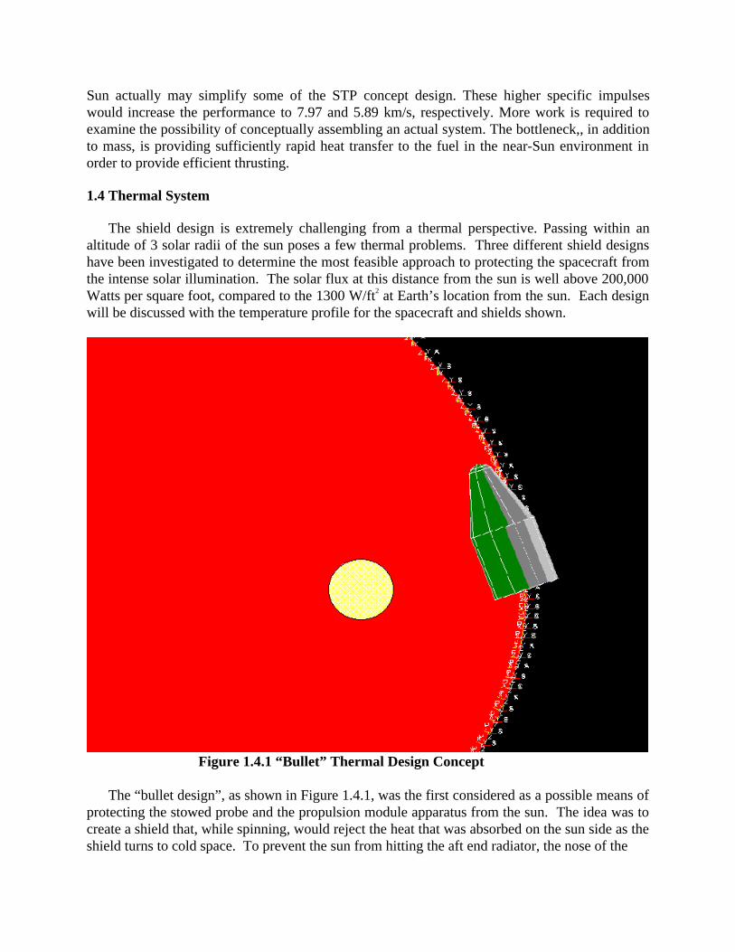
The shield design is extremely challenging from a thermal perspective. Passing within analtitude of 3 solar radii of the sun poses a few thermal problems. Three different shield designshave been investigated to determine the most feasible approach to protecting the spacecraft fromthe intense solar illumination. The solar flux at this distance from the sun is well above 200,000Watts per square foot, compared to the 1300 W/ft2 at Earth’s location from the sun. Each designwill be discussed with the temperature profile for the spacecraft and shields shown.
Figure 1.4.1 “Bullet” Thermal Design Concept
The “bullet design”, as shown in Figure 1.4.1, was the first considered as a possible means ofprotecting the stowed probe and the propulsion module apparatus from the sun. The idea was tocreate a shield that, while spinning, would reject the heat that was absorbed on the sun side as theshield turns to cold space. To prevent the sun from hitting the aft end radiator, the nose of the
Space cra ft Te m pe rature v e rsus Shie ld M LI e *, No sp in
-500
0
500
1000
1500
2000
2500
-20 -15 -10 -5 0 5 10 15 20
T ime (H ours )
Sp
ace
cra
ft T
em
pe
rtu
re (
C)
0.005
0.001
0.0005
0.0001
0.00005
0.00001
Pe ak S /C T e mpe rature Ve rsus M LI e *
0
500
1000
1500
2000
2500
0 0.001 0.002 0.003 0.004 0.005 0.006
M LI e *
Pe
ak
Te
mp
era
ture
(C
)
Figure 1.4.2 Figure 1.4.3
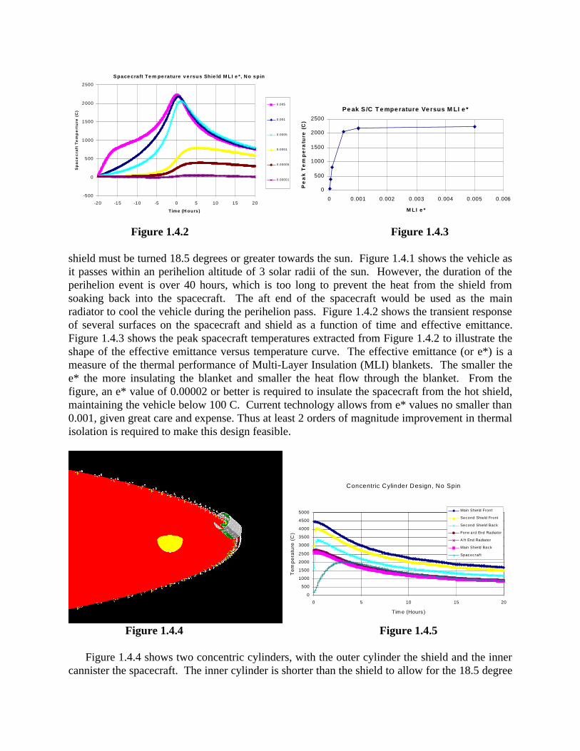
shield must be turned 18.5 degrees or greater towards the sun. Figure 1.4.1 shows the vehicle asit passes within an perihelion altitude of 3 solar radii of the sun. However, the duration of theperihelion event is over 40 hours, which is too long to prevent the heat from the shield fromsoaking back into the spacecraft. The aft end of the spacecraft would be used as the mainradiator to cool the vehicle during the perihelion pass. Figure 1.4.2 shows the transient responseof several surfaces on the spacecraft and shield as a function of time and effective emittance.Figure 1.4.3 shows the peak spacecraft temperatures extracted from Figure 1.4.2 to illustrate theshape of the effective emittance versus temperature curve. The effective emittance (or e*) is ameasure of the thermal performance of Multi-Layer Insulation (MLI) blankets. The smaller thee* the more insulating the blanket and smaller the heat flow through the blanket. From thefigure, an e* value of 0.00002 or better is required to insulate the spacecraft from the hot shield,maintaining the vehicle below 100 C. Current technology allows from e* values no smaller than0.001, given great care and expense. Thus at least 2 orders of magnitude improvement in thermalisolation is required to make this design feasible.
Concentric Cylinder Design, No Spin
0
500
1000
1500
2000
2500
3000
3500
4000
4500
5000
0 5 10 15 20
Tim e (Hours )
Te
mp
era
ture
(C
)
Main Shield Front
Second Shield Front
Second Shield Back
Forw ard End Radiator
A f t End Radiator
Main Shield Back
Spacecraf t
Figure 1.4.4 Figure 1.4.5
Figure 1.4.4 shows two concentric cylinders, with the outer cylinder the shield and the innercannister the spacecraft. The inner cylinder is shorter than the shield to allow for the 18.5 degree
solar umbra at 3 solar radii above the sun. Thus, the idea was to allow the sun to hit the inside ofthe shield on the back, as well as on the outside. However, as shown in Figure 1.4.5, theradiators on the spacecraft, which are the two ends of the canister, have large views to these veryhot surfaces. Figure 1.4.5 shows the resulting temperature response of the spacecraft as theshield passes the perihelion point in orbit.
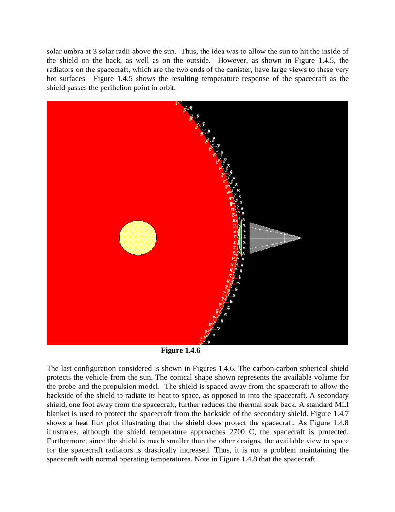
Figure 1.4.6
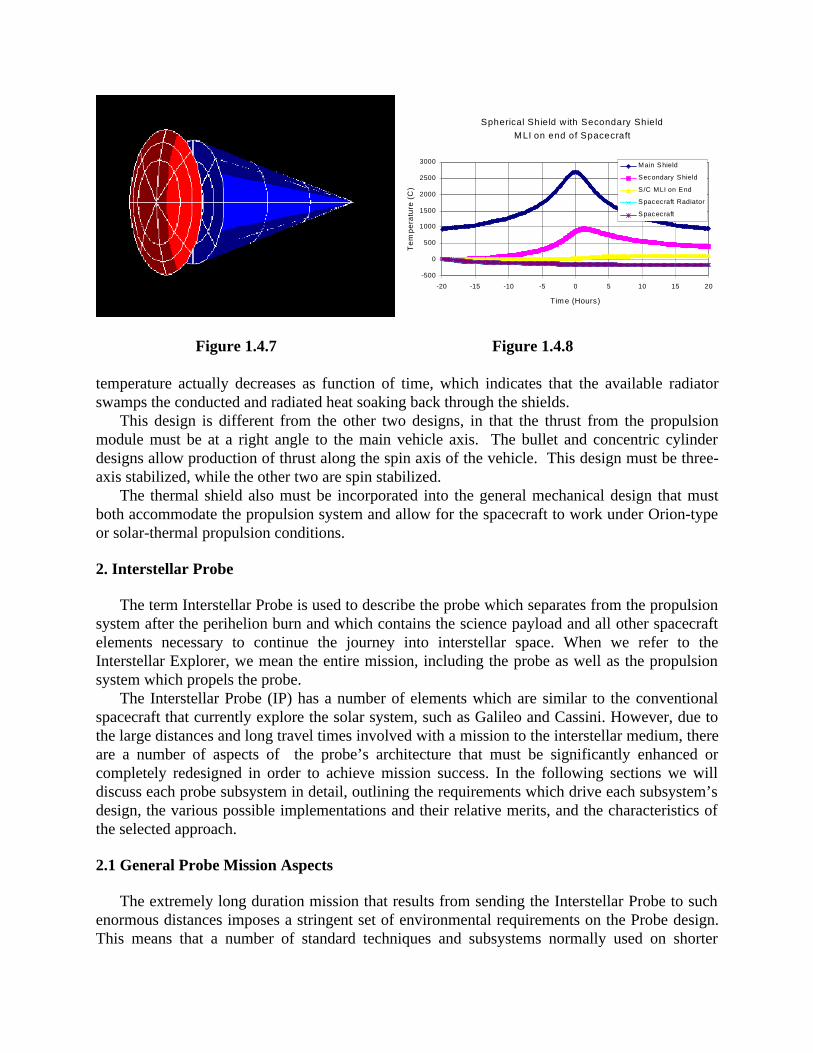
The last configuration considered is shown in Figures 1.4.6. The carbon-carbon spherical shieldprotects the vehicle from the sun. The conical shape shown represents the available volume forthe probe and the propulsion model. The shield is spaced away from the spacecraft to allow thebackside of the shield to radiate its heat to space, as opposed to into the spacecraft. A secondaryshield, one foot away from the spacecraft, further reduces the thermal soak back. A standard MLIblanket is used to protect the spacecraft from the backside of the secondary shield. Figure 1.4.7shows a heat flux plot illustrating that the shield does protect the spacecraft. As Figure 1.4.8illustrates, although the shield temperature approaches 2700 C, the spacecraft is protected.Furthermore, since the shield is much smaller than the other designs, the available view to spacefor the spacecraft radiators is drastically increased. Thus, it is not a problem maintaining thespacecraft with normal operating temperatures. Note in Figure 1.4.8 that the spacecraft
Spherical Shield w ith Secondary Shield
MLI on end of Spacecraft
-500
0
500
1000
1500
2000
2500
3000
-20 -15 -10 -5 0 5 10 15 20
Tim e (Hours)
Te
mp
era
ture
(C
)
Main Shield
Secondary Shield
S/C MLI on End
Spacecraft Radiator
Spacecraft
Figure 1.4.7 Figure 1.4.8
temperature actually decreases as function of time, which indicates that the available radiatorswamps the conducted and radiated heat soaking back through the shields.
This design is different from the other two designs, in that the thrust from the propulsionmodule must be at a right angle to the main vehicle axis. The bullet and concentric cylinderdesigns allow production of thrust along the spin axis of the vehicle. This design must be three-axis stabilized, while the other two are spin stabilized.
The thermal shield also must be incorporated into the general mechanical design that mustboth accommodate the propulsion system and allow for the spacecraft to work under Orion-typeor solar-thermal propulsion conditions.
2. Interstellar Probe
The term Interstellar Probe is used to describe the probe which separates from the propulsionsystem after the perihelion burn and which contains the science payload and all other spacecraftelements necessary to continue the journey into interstellar space. When we refer to theInterstellar Explorer, we mean the entire mission, including the probe as well as the propulsionsystem which propels the probe.
The Interstellar Probe (IP) has a number of elements which are similar to the conventionalspacecraft that currently explore the solar system, such as Galileo and Cassini. However, due tothe large distances and long travel times involved with a mission to the interstellar medium, thereare a number of aspects of the probe’s architecture that must be significantly enhanced orcompletely redesigned in order to achieve mission success. In the following sections we willdiscuss each probe subsystem in detail, outlining the requirements which drive each subsystem’sdesign, the various possible implementations and their relative merits, and the characteristics ofthe selected approach.
2.1 General Probe Mission Aspects
The extremely long duration mission that results from sending the Interstellar Probe to suchenormous distances imposes a stringent set of environmental requirements on the Probe design.This means that a number of standard techniques and subsystems normally used on shorter
missions within the solar system are not appropriate for a mission of this type. This reality forceda thorough top-down redesign of the architecture of the spacecraft and its subsystems. Forexample, it was deemed impractical to fly any components that used moving parts, such asmomentum wheels, scan platforms or thrusters that incorporated valves. Additionally, anysubsystem that required consumables was carefully evaluated. The only consumables permittedon the probe are blocks of solid Teflon used by the thrusters. Thrusters that require liquid orgaseous propellant were excluded.
The Interstellar Probe must have the characteristics of robustness, reliability and adaptability,since, for the most part, it must perform it's mission with minimal external help. The missionscenario which we have developed involves maintaining the IP in a dormant, cocooned modeduring the early phase of the mission while the propulsion system carries the probe through theplanetary swingbys and finally the near Sun swingby and perihelion burn maneuver. This phase,occurring well inside the solar system, includes the regions of highest radiation, acceleration, andtemperature. The probe is protected by the substantial structure and thermal shield of thepropulsion system. Since other spacecraft have already studied this region of space, there is noloss of science return by having the probe turned off.
2.1.1 Shakedown Cruise Period
Once the propulsion system has completed the Sun swingby it is left behind and the probecontinues on its journey. At this point the initial checkout of the probe commences. During thisperiod two way communication with the spacecraft is required. The duration of the InterstellarProbe shakedown period is dependent on how long two-way communications can be maintained.The various communication system approaches (microwave and optical) for the primary longrange system are discussed in detail in a later section. However, these systems are verydirectional, so extremely good pointing is required to maintain a two way link. If there is aproblem with the attitude control system, then these system are not useable. Most conventionalspacecraft employ a low rate omni-directional link in order to allow commands to be uplinked,regardless of the spacecraft orientation. Due to the power gain of omni systems, they are aninappropriate choice for a secondary communication system on the Interstellar Probe. Hence, anultraminiature Ka band system will serve as the two-way communication for the probe during itsshakedown period. The size of the antenna is very small to minimize mass and to achieve areasonable amount of onmi-directionality in the beam. As long as the probe can maintain crudesun pointing, the Ka system will be able to establish a link with the DSN. One bit per seconddownlink is possible with a 2 watt amplifier and 20 cm dish antenna.
Two way communications allows problems to be diagnosed and remedial action taken (suchas a software upload) during the shakedown portion of the mission. Since the probe is moving at20 AU/ year, it is out of range for two way communication in about six months. However,because the uplink margin is much higher for the Ka system than the downlink, due to the use ofmore powerful transmitters on Earth, it would still be possible to get commands into the probefor a substantially longer time. If the optical downlink system is also working properly, then twoway communications can still be maintained.
2.1.2 Prime Science Period
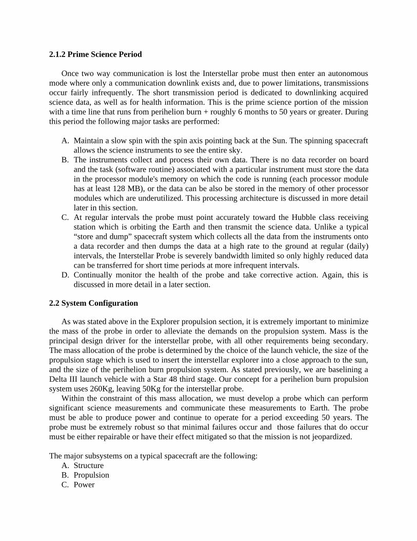
Once two way communication is lost the Interstellar probe must then enter an autonomousmode where only a communication downlink exists and, due to power limitations, transmissionsoccur fairly infrequently. The short transmission period is dedicated to downlinking acquiredscience data, as well as for health information. This is the prime science portion of the missionwith a time line that runs from perihelion burn + roughly 6 months to 50 years or greater. Duringthis period the following major tasks are performed:
A. Maintain a slow spin with the spin axis pointing back at the Sun. The spinning spacecraftallows the science instruments to see the entire sky.
B. The instruments collect and process their own data. There is no data recorder on boardand the task (software routine) associated with a particular instrument must store the datain the processor module's memory on which the code is running (each processor modulehas at least 128 MB), or the data can be also be stored in the memory of other processormodules which are underutilized. This processing architecture is discussed in more detaillater in this section.
C. At regular intervals the probe must point accurately toward the Hubble class receivingstation which is orbiting the Earth and then transmit the science data. Unlike a typical“store and dump” spacecraft system which collects all the data from the instruments ontoa data recorder and then dumps the data at a high rate to the ground at regular (daily)intervals, the Interstellar Probe is severely bandwidth limited so only highly reduced datacan be transferred for short time periods at more infrequent intervals.
D. Continually monitor the health of the probe and take corrective action. Again, this isdiscussed in more detail in a later section.
2.2 System Configuration
As was stated above in the Explorer propulsion section, it is extremely important to minimizethe mass of the probe in order to alleviate the demands on the propulsion system. Mass is theprincipal design driver for the interstellar probe, with all other requirements being secondary.The mass allocation of the probe is determined by the choice of the launch vehicle, the size of thepropulsion stage which is used to insert the interstellar explorer into a close approach to the sun,and the size of the perihelion burn propulsion system. As stated previously, we are baselining aDelta III launch vehicle with a Star 48 third stage. Our concept for a perihelion burn propulsionsystem uses 260Kg, leaving 50Kg for the interstellar probe.
Within the constraint of this mass allocation, we must develop a probe which can performsignificant science measurements and communicate these measurements to Earth. The probemust be able to produce power and continue to operate for a period exceeding 50 years. Theprobe must be extremely robust so that minimal failures occur and those failures that do occurmust be either repairable or have their effect mitigated so that the mission is not jeopardized.
The major subsystems on a typical spacecraft are the following:A. StructureB. PropulsionC. Power
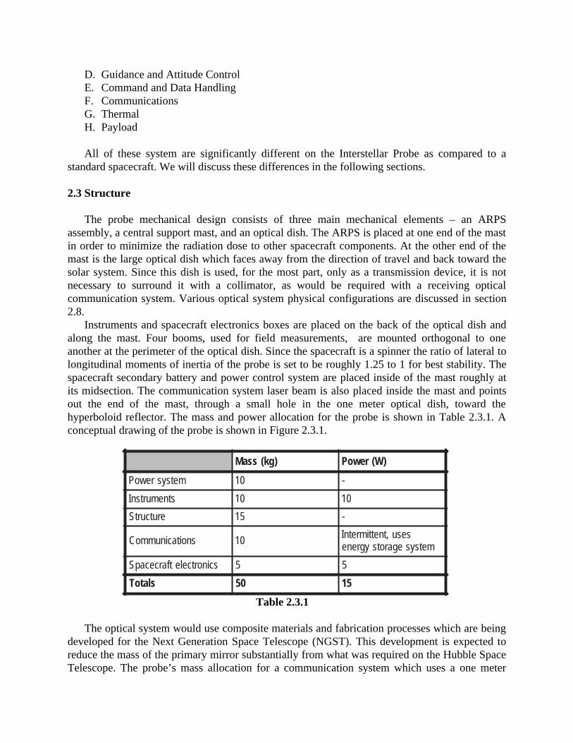
D. Guidance and Attitude ControlE. Command and Data HandlingF. CommunicationsG. ThermalH. Payload
All of these system are significantly different on the Interstellar Probe as compared to astandard spacecraft. We will discuss these differences in the following sections.
2.3 Structure
The probe mechanical design consists of three main mechanical elements – an ARPSassembly, a central support mast, and an optical dish. The ARPS is placed at one end of the mastin order to minimize the radiation dose to other spacecraft components. At the other end of themast is the large optical dish which faces away from the direction of travel and back toward thesolar system. Since this dish is used, for the most part, only as a transmission device, it is notnecessary to surround it with a collimator, as would be required with a receiving opticalcommunication system. Various optical system physical configurations are discussed in section2.8.
Instruments and spacecraft electronics boxes are placed on the back of the optical dish andalong the mast. Four booms, used for field measurements, are mounted orthogonal to oneanother at the perimeter of the optical dish. Since the spacecraft is a spinner the ratio of lateral tolongitudinal moments of inertia of the probe is set to be roughly 1.25 to 1 for best stability. Thespacecraft secondary battery and power control system are placed inside of the mast roughly atits midsection. The communication system laser beam is also placed inside the mast and pointsout the end of the mast, through a small hole in the one meter optical dish, toward thehyperboloid reflector. The mass and power allocation for the probe is shown in Table 2.3.1. Aconceptual drawing of the probe is shown in Figure 2.3.1.
)gk(ssaM )W(rewoP
metsysrewoP 01 -
stnemurtsnI 01 01
erutcurtS 51 -
snoitacinummoC 01 sesu,tnettimretnImetsysegarotsygrene
scinortceletfarcecapS 5 5
slatoT 05 51
Table 2.3.1
The optical system would use composite materials and fabrication processes which are beingdeveloped for the Next Generation Space Telescope (NGST). This development is expected toreduce the mass of the primary mirror substantially from what was required on the Hubble SpaceTelescope. The probe’s mass allocation for a communication system which uses a one meter
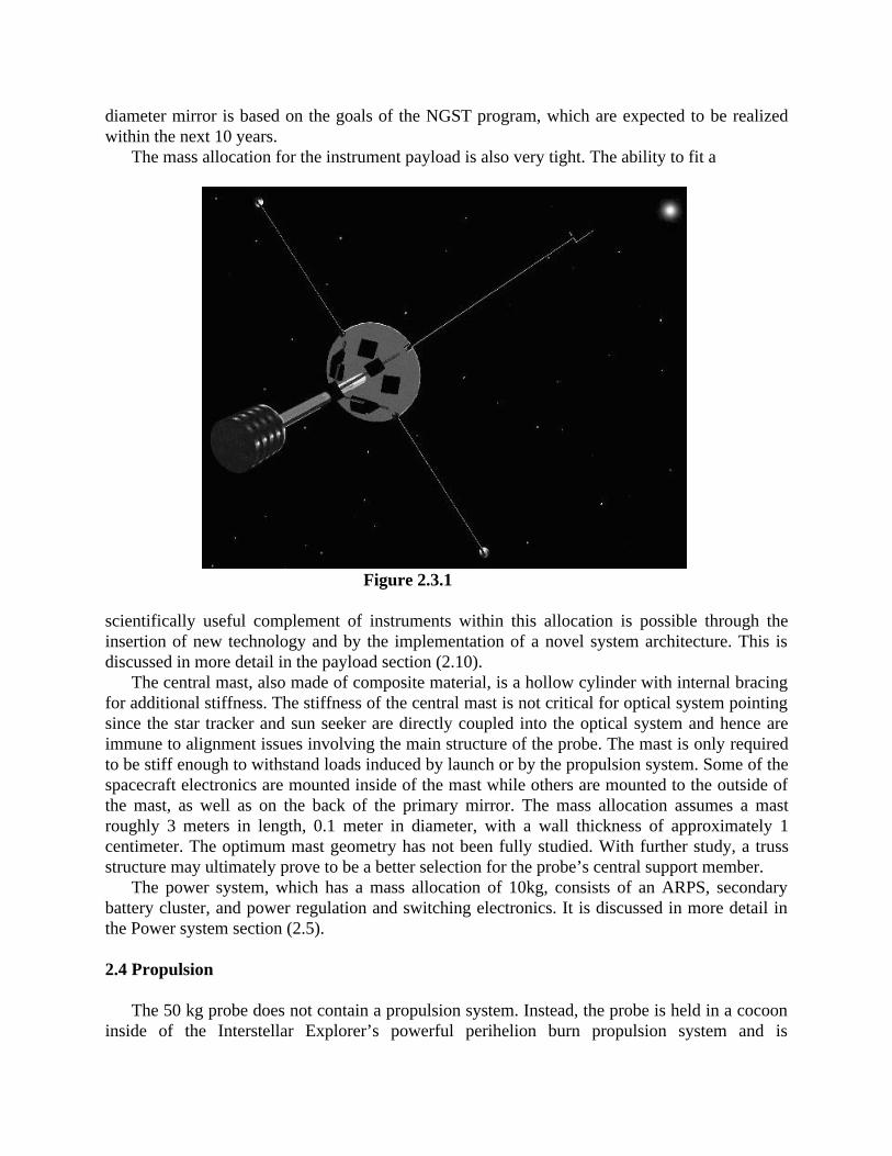
diameter mirror is based on the goals of the NGST program, which are expected to be realizedwithin the next 10 years.
The mass allocation for the instrument payload is also very tight. The ability to fit a
Figure 2.3.1
scientifically useful complement of instruments within this allocation is possible through theinsertion of new technology and by the implementation of a novel system architecture. This isdiscussed in more detail in the payload section (2.10).
The central mast, also made of composite material, is a hollow cylinder with internal bracingfor additional stiffness. The stiffness of the central mast is not critical for optical system pointingsince the star tracker and sun seeker are directly coupled into the optical system and hence areimmune to alignment issues involving the main structure of the probe. The mast is only requiredto be stiff enough to withstand loads induced by launch or by the propulsion system. Some of thespacecraft electronics are mounted inside of the mast while others are mounted to the outside ofthe mast, as well as on the back of the primary mirror. The mass allocation assumes a mastroughly 3 meters in length, 0.1 meter in diameter, with a wall thickness of approximately 1centimeter. The optimum mast geometry has not been fully studied. With further study, a trussstructure may ultimately prove to be a better selection for the probe’s central support member.
The power system, which has a mass allocation of 10kg, consists of an ARPS, secondarybattery cluster, and power regulation and switching electronics. It is discussed in more detail inthe Power system section (2.5).
2.4 Propulsion
The 50 kg probe does not contain a propulsion system. Instead, the probe is held in a cocooninside of the Interstellar Explorer’s powerful perihelion burn propulsion system and is

mechanically ejected by a stored energy system (spring) after the swingby of the sun iscompleted. The ejection increases the acceleration of the probe somewhat while slowing downthe expended propulsion system. The probe coasts out of the solar system with the propulsionsystem body drifting behind at gradually greater and greater distances. The propulsion systemdoes not interfere with communication back to the Earth due to a small asymmetric thrust appliedto the propulsion system structure which causes it to slowly drift off of the trajectory of theprobe.
2.5 Power
The choices for the primary power system for an interstellar probe are severely limited. Solarpanels are not feasible because of the significant distance from the sun. For example, assuming atypical solar cell conversion efficiency of 20% and a solar input at 1000 AU of 1.35x10⁻⁷
Watts/cm2, we would need a solar panel about 1Km square in order to obtain 1 Watt of spacecraftelectrical power. While it may be feasible to design a probe that only consumes 1 Watt of power,the mass needed for the solar panels is prohibitive.
2.5.1 Primary Power – Battery Concept
A battery acting as the primary source of power is theoretically possible but there aresignificant practical limitations. Lithium batteries are undergoing significant development at thistime and their energy densities have been doubling roughly every ten years. Assuming that thisprogress continues, we could anticipate a battery which could supply about 8000 Watt-hrs/Kg bythe year 2030. If we allocate 10 Kg for the battery system on our probe, it would supply 80,000Watt-hrs of energy. There are probe operational modes which could possibly support using onlythis much energy for a 50 year mission. One scenario involves having all instruments go into adormant mode for regular intervals of roughly one week. A low power clock would mark thetime and wake them up for a short period of data acquisition and data transmittal. For example, ifwe assume that they take data for about four hours while consuming a total of 5 watts and thenthe probe transmits this data to Earth for 10 minutes using 12 watts (see the Communicationsystem section), then the probe would use roughly 22 Watt-hrs during this period of activity.Since there would be ~2500 periods of activity during the mission, the total energy consumptionwould be 2500 x 22 = 55,000 Watt-hrs, which is within the capability of our proposed battery.However, there are a number of other factors which make this difficult to achieve. First of all, itis unlikely that the doubling of energy density will increase indefinitely. Indeed, batteryresearchers believe that the rate of increase in energy density may already be tapering off due tothe physics of the devices. Secondly, all batteries have a self discharge rate which is roughly 1%per year at room temperature. The discharge rate is much better at the cold temperatures wherethe probe would be operating (100-150K), but at that temperature the batteries barely produceany output. Hence, in order to use a battery as the primary power source, significantimprovement in energy density and cold temperature operation would have to be achieved.
2.5.2 Primary Power – ARPS concept
The most obvious choice for a power system on a mission of this type is an AdvancedRadioisotope Power System (ARPS). These have flown on many missions, such as Ulysses,
Cassini, and Galileo, with an unblemished safety and reliability record. Existing designs supplyabout 4 electrical Watts per kilogram. The probe has a continual power consumption of about 15Watts, so an ARPS weighing approximately 4 Kg is needed. Due to the radioactive output of theARPS, it is necessary to mount it as far away from the other spacecraft components as possible.Hence, it is mounted at the far end of the probe’s central support mast, at a distance of 3 meters.The ARPS also generates a significant amount of waste heat. On most spacecraft this would be aserious concern. However, on the Interstellar Probe the waste heat is needed to keep thespacecraft at a reasonable temperature. The use of this waste heat is discussed in more detail inthe Thermal System section.
2.5.3 Secondary Power
The probe has been designed to draw a minimal amount of power during normal operations.The primary power system is capable of providing enough power for all nominal payload andspacecraft functions, including intermittent attitude adjustments and operation of the opticalcommunication system. However, the primary power system does not provide a robust marginfor operation of the thrusters and the communication system during the life of the mission.Although only a few watts of laser power are required to provide a positive communication linkmargin, it is prudent to be able to have sufficient power reserves in order to boost the signal inthe event of emergencies or degradation of optical transmission properties. Also, during normalattitude adjustments to point the communication dish at the Earth receiver, very little power isrequired for the thrusters, but it is possible that significant thruster firing would be required in theevent of an attitude anomaly.
Hence, a secondary power system has been baselined for this mission to supply power duringtransient peak loads for both the communication and attitude control systems. There areessentially two methods for long term storage of energy: a sealed rechargeable chemical batteryor a bank of capacitors. Both systems are typically capable of providing significant amounts ofpower essentially instantaneously for brief periods. The operating scenario for use of thesecondary power system is that it would be trickle charged by the primary system during thelarge fraction of time when the probe is neither communicating nor doing precision pointing.Power would be drawn from the system as needed during the regular (weekly) telemetrycommunication periods. The selection of an appropriate secondary power system is notstraightforward for a mission of this duration. This is because chemical batteries have an energydensity that is many thousands of times higher than capacitors, but there is no test data which hasestablished that batteries have a lifetime exceeding fifty years. Rather than be forced to fly acapacitor bank, a scheme which maximizes the life of the battery system has been developed.
First of all, since battery dry storage life is much higher than wet storage life, the secondarysystem will consist of a number of small batteries stored in the dry state. The lifetime of abattery in the dry state is somewhat dependent on temperature. The main support beam of theprobe has a steep temperature differential along its due to the ARPS being at one end and theradiative optical communications dish at the other end. The secondary battery would be placedinside the probe’s central support beam at a location along the post so that its thermalenvironment was optimal for long life. Squibs (pyrotechnic devices) would be used to activateeach battery in turn when the previously utilized battery is no longer holding its charge. Forexample, four small batteries, each used in the wet state for fifteen years, would easily suffice forthe fifty year mission.
Secondly, the life of a wet battery is strongly determined by the number of discharge cyclesand by the depth of discharge. In order to maximize battery life the depth of discharge will bekept to a minimum. The amount of energy that needs to be available from the active battery inorder to provide significant margin for the communication and attitude control systems is 60Watts for 10 minutes. The batteries types which are appropriate candidates for this mission areeither Nickel Hydrogen or a variant of a Lithium battery, such as Lithium-Ion. Since a currentlyavailable Lithium Ion battery has a specific energy of approximately 200 Watt-hr/Kg, and we areassuming a 20% depth of discharge, a 250 gram battery would be sufficient. Since four batterieswould be flown, the total mass allocated to secondary batteries is 1Kg.
2.5.4 Power Regulation and Distribution
The configuration of the complete power system would be fairly conventional, with theprimary power bus tied directly to the ARPS and regulated using shunt regulators. The batterywould be used for current needs beyond those supplied by the ARPS and boost regulation wouldbe employed to boost the battery’s voltage up to the specified bus voltage.
As mentioned previously, minimizing mass is the key factor governing the design of theInterstellar Probe. Since both the spacecraft harness and instrument/subsystem low voltageregulators can be quite massive, it is prudent to select a power distribution system which is aslight as possible. One standard tradeoff involves the number of regulated voltages generated bythe main regulator, located proximal to the ARPS, versus the number of distributed regulators ineach of the subsystems. In many modern spacecraft the main power bus is a single voltage (e.g.28 volts) and each instrument or subsystem has their own power supply regulator which is usedto generate a myriad of voltages (e.g. ± 5, ± 6, ± 12, ± 15) that are unique to the particularinstrument. This clearly minimizes the mass of the harness but the combined mass of theregulators is substantial. When the main spacecraft regulator develops all the required lowvoltages itself, then the harness becomes heavy.
A unique and low mass solution for the Interstellar Probe is facilitated by the use ofextremely low voltage inter-communication ASICS (referred to as “SAC”s when discussed inmore detail in section 2.7) and processor modules. Redundant inter-communication ASICS areconnected to each instrument and spacecraft subsystem and are used to collect relatively raw datafrom the various sensors (e.g. particle detectors, start trackers, etc). They transmit the data at highrates via wireless technology to a cluster of spacecraft processors. These units all operate at thesame voltage which is anticipated to be less than 1.8 volts. Because the inter-communicationASICS and processor modules have been designed to consume very little power, it is feasible tosatisfy their power needs by using switched capacitor regulators. Switched capacitor regulatorsare finding increasing use in the computer industry and the fabrication of these devices hastrended toward using Silicon on Sapphire (SOS) radiation hard technology. These regulatorsprovide very robust and very lightweight regulation, but they do not provide isolation. However,on a small, low power spacecraft such as the Interstellar Probe, isolation between primary andsecondary sides may not be necessary.
Of course, each instrument and subsystem will still require some higher voltages for variouspurposes, such as specialized signal conditioning, detector bias voltages or high voltage formicrochannel plates. The main bus voltage would be selected so as to be at the voltage for whichthe current drain is the highest. For example, if a majority of the subsystems use +5 volts, thenthe bus would be selected to run at +5 volts. The switched capacitor regulators are also quite
suitable for generating both plus and minus voltages which are multiples of the bus voltage, suchas ±10 and ±15 volts. The +5 volt main bus would also be used as the primary voltage for highvoltage power supplies which use a standard voltage multiplier (Cockcroft-Walton) topology togenerate voltages exceeding 100 volts. In order to save mass, it is fairly critical that instrumentand spacecraft subsystem designers design their electronics and detectors to use as few voltagesas possible.
In summary, the pervasive use of distributed low-power processor and inter-communicationmodules, coupled with compact switched capacitor regulators and an instrument designphilosophy that minimizes the number of unique voltages, allows the spacecraft bus to be at asingle voltage (e.g. +5 V) with minimal mass used for regulators in any of the instruments orspacecraft subsystems.
2.6 Guidance and Attitude Control
The conceptual design of an attitude determination and control system for the proposedInterstellar Probe vehicle is straightforward, and perhaps even simple. We need only point theantenna boresight at a receiver on Earth once a day to within the beamwidth of the laser signal,estimated to be 0.15 arcsecond. This corresponds to an absolute pointing and controlrequirement of ±0.075 arcsecond (3-σ). It is at this point that reality and engineering begin tobecome problems. In order to realistically assess the possibility of meeting such a tightrequirement, a detailed and thoughtful analysis of error sources is required. A number ofconsiderations go into this error analysis, including:
A. Trajectory Knowledge. It is necessary to have onboard clock and ephemerides to trackthe receiving station and vehicle so that the vehicle-to-station vector orientation is knownsufficiently accurately to effect data transfer. Denote the pointing angle uncertainty byσTRAJ.
B. Transmitter Boresight Pointing Knowledge. There are several factors contributing to thedefinition of boresight pointing knowledge. First, there is knowledge of a fiducial frame,which we would expect to be defined by a high precision star tracker. Denote theabsolute pointing knowledge of the tracker by σSTCAM. Then we must know the alignmentof the star tracker relative to the laser antenna. Let the uncertainty in this alignment(projected on the pointing axis) be σFIDUCIAL.
C. Boresight Control. In order to minimize complexity, mass and power requirements, thevehicle is proposed to be stabilized as slowly rotating about the axis of the lasertransmitter antenna. Preliminary mass properties estimates indicate that a very favorableinertia ratio can be easily achieved, thus minimizing the effect of disturbance torques(solar radiation, for example) on the vehicle and, therefore, complexity of the attitudecontrol system and attitude fuel requirements. Then the function of the attitude controlactuators is to move the spacecraft angular momentum vector to follow the receivingstation. An immediately perceived difficulty here is in aligning the vehicle principalinertia axis to the antenna boresight and maintaining co-alignment over time. Even smallchanges in inertia, for example due to propellant expenditures, can move the principalaxis from the required position in the vehicle and potentially require unfeasible activecontrol. Denote the total pointing error from these control-related sources by σCONTROL.
Then it is immediate that we must have σTOTAL # (0.075 arcsec)/3 = 0.025 arcsec, where
Achieving such accuracy for all of these errors appears daunting, but perhaps not impossible inthe intermediate term. Addressing them individually:
2.6.1 Trajectory and Clock Errors
Because of the very long light times involved, it is perceived that Interstellar Probe wouldnecessarily operate open loop, with virtually no uploads. In particular, we presume the necessityto integrate all trajectories on-board to sufficient accuracy to know where to point. For example,at 100 AU after 5 years, say, pointing to 0.01 arcsec requires that the relative spacecraft-to-Earthvector be known to approximately 750 km. in the computational coordinate system. This isabout 0.05 ppm, and seems reasonable computationally.
2.6.2 Transmitter Boresight Pointing Knowledge
As noted above, the two immediate contributors to knowledge are measurement andalignment of the measuring device. First, consider the star tracker. Commercially availabletrackers which measure to better than an arcsecond are readily available today, and wide field-of-view trackers with accuracy on the order of 0.1 arcsecond are in final development. Thus itappears that meeting Interstellar Probe’s knowledge from a tracking point of view is achievablein the foreseeable future. The show-stopping problem here is that current development efforts donot have the mass and power constraints of IP. This is a clear need for development. There isalso a legitimate need for a star catalog with accuracy commensurate with the desired pointing.We note that IP’s dynamics are so passive that tracker integration time should pose no problem.
The other error source here is alignment of the transmitter boresight to the fiducial framedefined by the star tracker reference. This error source can be essentially eliminated by using thesame optical system for the tracker and the transmitter. While calibration errors cannot becompletely eliminated, this procedure should allow that they be measured and compensated onorbit.
2.6.3 Boresight Control
Boresight control may be the most technically challenging part of the IP attitude systembecause of perturbations, control quantization and fuel requirements, to begin. As noted above,we propose designing the vehicle to rotate slowly about the nominal transmitter boresight. Thishas the clear advantage of tending to cancel disturbance torques, the major one appearing to besolar pressure acting through a center-of-pressure to center-of-mass offset. Since early on, thevehicle will be required to execute significant attitude maneuvers to track Earth (90°/6 months at1 AU from Earth), this disturbance cannot easily be ignored. It is fortunate that both angularmotion required decreases as 1/r from Earth, and the solar pressure decreases as 1/r2 from the sun.There is a clear trade between higher rotation rate for disturbance cancellation and fuel use tomove more angular momentum while tracking.
.2
CONTROL
2
FIDUCIAL
2
STCAM
2
TRAJ
2
TOTAL σ+σ+σ+σ=σ
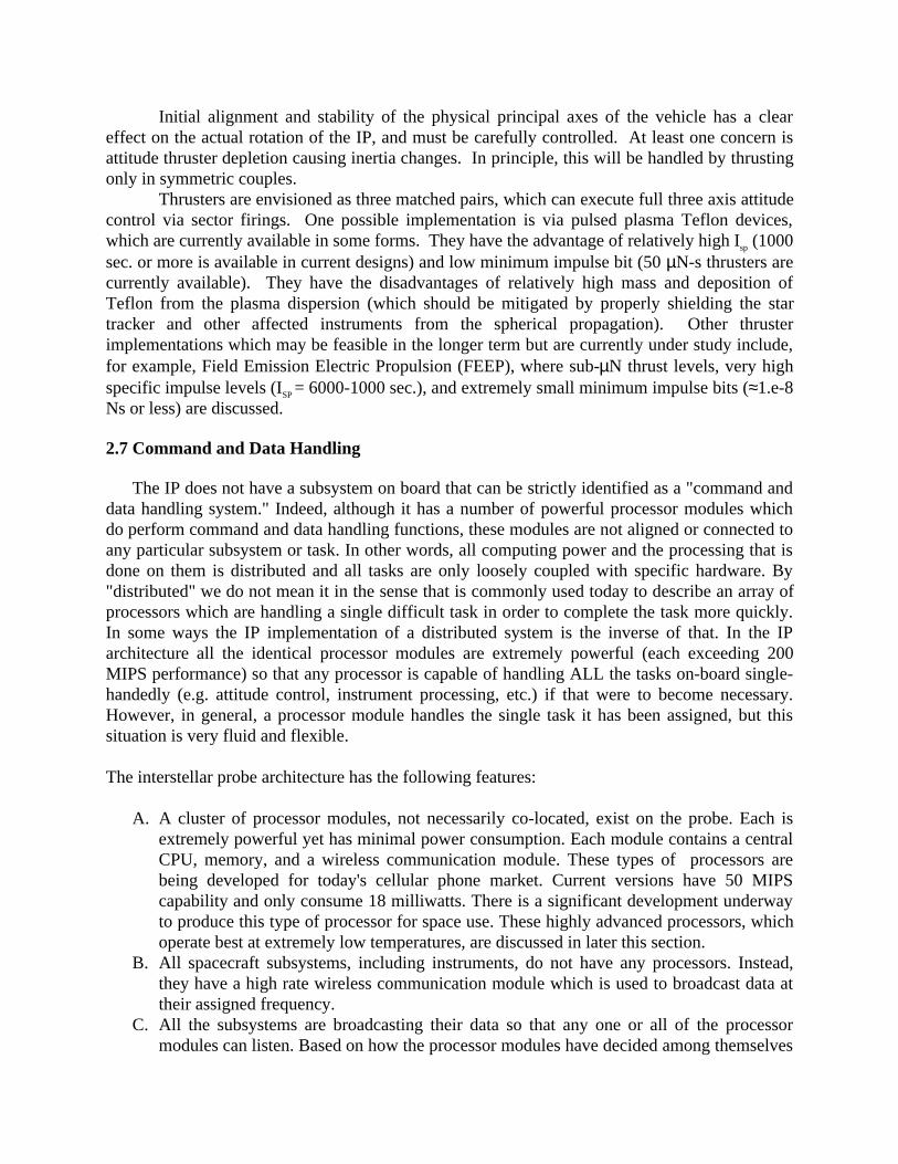
Initial alignment and stability of the physical principal axes of the vehicle has a cleareffect on the actual rotation of the IP, and must be carefully controlled. At least one concern isattitude thruster depletion causing inertia changes. In principle, this will be handled by thrustingonly in symmetric couples.
Thrusters are envisioned as three matched pairs, which can execute full three axis attitudecontrol via sector firings. One possible implementation is via pulsed plasma Teflon devices,which are currently available in some forms. They have the advantage of relatively high Isp (1000sec. or more is available in current designs) and low minimum impulse bit (50 µN-s thrusters arecurrently available). They have the disadvantages of relatively high mass and deposition ofTeflon from the plasma dispersion (which should be mitigated by properly shielding the startracker and other affected instruments from the spherical propagation). Other thrusterimplementations which may be feasible in the longer term but are currently under study include,for example, Field Emission Electric Propulsion (FEEP), where sub-µN thrust levels, very highspecific impulse levels (ISP = 6000-1000 sec.), and extremely small minimum impulse bits (≈1.e-8Ns or less) are discussed.
2.7 Command and Data Handling
The IP does not have a subsystem on board that can be strictly identified as a "command anddata handling system." Indeed, although it has a number of powerful processor modules whichdo perform command and data handling functions, these modules are not aligned or connected toany particular subsystem or task. In other words, all computing power and the processing that isdone on them is distributed and all tasks are only loosely coupled with specific hardware. By"distributed" we do not mean it in the sense that is commonly used today to describe an array ofprocessors which are handling a single difficult task in order to complete the task more quickly.In some ways the IP implementation of a distributed system is the inverse of that. In the IParchitecture all the identical processor modules are extremely powerful (each exceeding 200MIPS performance) so that any processor is capable of handling ALL the tasks on-board single-handedly (e.g. attitude control, instrument processing, etc.) if that were to become necessary.However, in general, a processor module handles the single task it has been assigned, but thissituation is very fluid and flexible.
The interstellar probe architecture has the following features:
A. A cluster of processor modules, not necessarily co-located, exist on the probe. Each isextremely powerful yet has minimal power consumption. Each module contains a centralCPU, memory, and a wireless communication module. These types of processors arebeing developed for today's cellular phone market. Current versions have 50 MIPScapability and only consume 18 milliwatts. There is a significant development underwayto produce this type of processor for space use. These highly advanced processors, whichoperate best at extremely low temperatures, are discussed in later this section.
B. All spacecraft subsystems, including instruments, do not have any processors. Instead,they have a high rate wireless communication module which is used to broadcast data attheir assigned frequency.
C. All the subsystems are broadcasting their data so that any one or all of the processormodules can listen. Based on how the processor modules have decided among themselves
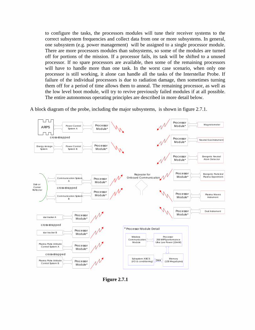
to configure the tasks, the processors modules will tune their receiver systems to thecorrect subsystem frequencies and collect data from one or more subsystems. In general,one subsystem (e.g. power management) will be assigned to a single processor module.There are more processors modules than subsystems, so some of the modules are turnedoff for portions of the mission. If a processor fails, its task will be shifted to a unusedprocessor. If no spare processors are available, then some of the remaining processorswill have to handle more than one task. In the worst case scenario, when only oneprocessor is still working, it alone can handle all the tasks of the Interstellar Probe. Iffailure of the individual processors is due to radiation damage, then sometimes turningthem off for a period of time allows them to anneal. The remaining processor, as well asthe low level boot module, will try to revive previously failed modules if at all possible.The entire autonomous operating principles are described in more detail below.
A block diagram of the probe, including the major subsystems, is shown in figure 2.7.1.
star tracker A
star tracker B
Dust Instrument
Magnetometer
Neutral Gas Instrument
Energetic NeutralAtom Detector
Energetic Particles/Plasma Experiment
Plasma WavesInstrument
Communication SystemA
ProcessorModule*
Communication SystemB
ARPS
Energy storageSystem
Power ControlSystem A
Power ControlSystem B
Dish orCorner
Reflector
cross-strapped
cross-strapped
cross-strapped
Plasma Pulse AttitudeControl System A
Plasma Pulse AttitudeControl System B
Repeater forOnboard Communication
cross-strapped
ProcessorModule*
ProcessorModule*
ProcessorModule*
ProcessorModule*
ProcessorModule*
ProcessorModule*
ProcessorModule*
ProcessorModule*
ProcessorModule*
ProcessorModule*
ProcessorModule*
ProcessorModule*
ProcessorModule*
* Processor Module Detail
Processor200 MIPS performance
Ultra Low Power (10mW)
WirelessCommunication
Module
Subsystem ASICS(I/O & conditioning)
Memory(128 Megabytes)DMA
Figure 2.7.1
2.7.1 Low Power Electronics
The large and lucrative portable appliances market will drive the semiconductor industry tomake significant improvements to CMOS technology over the next ten years that will alsobenefit the Interstellar Probe. Fabrication processes developed to minimize operating voltage willbe especially beneficial for building application specific integrated circuits (ASICs) for the IP.The new manufacturing technology will likely have excellent total dose and single event latchupradiation tolerance. However, using mass-market catalog parts on the probe will be moredifficult. Chips developed for commercial applications will, with rare exceptions, have noprovisions for detecting and responding to radiation induced soft errors. Error correctingtechniques can overcome single event errors for large memory arrays but solving this problemfor logic devices is best accomplished within a chip rather than through external mechanisms.Hence, most Interstellar Probe logic will be contained within ASICs that use internal circuitsimmune to radiation induced soft errors.
Dramatic reductions in CMOS power consumption appear feasible by lowering voltage.Switching power, P, of CMOS circuits is given by P = α C V 2 f where α is the circuitactivity factor, C is the total circuit load capacitance, V is the transition voltage, and f is theoperating frequency. However, as voltage is lowered, the gate potential of each off transistorapproaches that device’s threshold, Vt. Since off current is exponentially related to the differencebetween gate voltage and Vt, operating logic circuits with a low power supply also leads toincreased static leakage current. Burr, et. al. have shown that total energy is minimizedwhen switching energy and leakage energy are equal. Burr has also shown that the energy-timeproduct is optimized when V = 3Vt and that Vt is proportional to the thermal voltage (26mV @300°K, 6.7mV @ 77°K ). Hence at Interstellar Probe’s very low operating temperatures, apower supply as low as a few tens of millivolts is feasible and will result in over a three order ofmagnitude power savings compared to current technology.
Power can also be reduced, although less dramatically, through careful attention to theremaining factors in the power equation. Architecture and logic design can be optimized tominimize signal transitions, i.e. α, the activity factor. Parallel versus serial architecture tradesthat consider transition power as well as area and speed are possible. Output glitches can bereduced or eliminated by using hazard free logic design. Signal evaluation order can berearranged to reduce intermediate transitions. Computer Aided Engineering tools to supportpower optimized design are now commercially available and will be in widespread use whendetailed design of the Interstellar Probe electronics commences. Load capacitance can be reducedby careful attention to device sizing and minimizing wire length although full custom or standardcell design methodologies are needed to achieve this benefit. Insulating substrate technology canalso reduce load capacitance although that technology may be incompatible with extremereductions in power supply voltage.
Extreme voltage scaling as described above is not without difficulty. Controlling devicethreshold variations across a die is difficult especially to the values required for subvolt powersupplies. One demonstrated solution to this problem controls Vt by building devices with nearzero or even negative threshold voltage and then adjusting substrate potential to increase thethreshold to the desired value. Work now in progress will use a feedback network to generate andcontrol the substrate bias voltage on-chip. The bias circuit will also adjust substrate potential tocompensate for temperature and supply variations. Threshold uniformity will still limit the size
of the largest chip built using these principles but devices with over 100,000 transistors havealready been successfully demonstrated.
Larger designs can be built using more complex fabrication processes. Using separate P andN wells will allow device characteristics of both FET types to be independently adjusted. If thewell regions extend over sufficiently small die regions than threshold voltage will be sufficientlyuniform to support very low voltage operation. To ensure adequate noise margin,communications between uniform threshold regions may require special provisions. Potentialsolutions could include differential signaling or logic constructed with higher threshold devices.
Extreme low voltage CMOS faces additional challenges. Signal swings are very low and maybe sensitive to electrical noise from many sources. Careful physical layout and construction ofcircuit cards can lessen these effects but a practical electronics system functioning with a 50mVpower supply at cryogenic temperatures has not yet been demonstrated. Power efficientinterfaces between low voltage CMOS and traditional logic must also be developed. Theseinterface circuits should ideally be integrated on low power parts to ease system design andminimize board area. Power conversion circuits compatible with low power requirements mustbe developed. These circuits must efficiently convert spacecraft power bus voltage to the finalapplication value. Noise immunity and tolerance to input variations must also be acceptable.While these challenges are formidable, they can be solved by the time Interstellar Probe startsdetailed design.
2.7.2 Autonomous Operation
The architecture for the Interstellar Probe system is logically similar to familiar spacecraftarchitectures: a spacecraft system consisting of various subsystems which have individual areasof responsibility - an attitude control subsystem, a navigation subsystem, a power subsystem, athermal subsystem, various instrument subsystems, etc. Physically the system is implementeddifferently. Each subsystem consists of two major parts; the first is a set of two or moreSensor/Actuator/Communication (SAC) modules and the second is the Control Logic &Communication (CLC) processes that control the subsystem. The CLC processes are mappedonto a set of physical processors, all of which are identical and any of which can communicatewith a SAC. Any processor can do any other processor’s jobs. There are many more processorsthen are needed to do the job. It is expected that processors will fail, sometimes completely andsometimes only partially. The architecture works with a “quorum” of computers. Others are leftpowered down, are duty cycled, and are available if needed.
2.7.2.1 Autonomy/Fault Tolerance/Safing
The approach to autonomy, fault tolerance, and safing is hierarchical. In this discussionautonomy refers to true decision making on the part of the system or subsystem; fault tolerancerefers to the ability to detect and recover from a fault condition; and safing is the act of shuttingdown and passing fault conditions on to a higher authority. A subsystem can pass a safe or faultcondition to a higher authority. Each level of the architecture is responsible for its ownautonomy, fault tolerance, and safing.
Commanding of each subsystem is accomplished using goals. A goal is expressed as“maintaining a defined system state for a defined period”. Goals have priorities and a subsystemis responsible for fulfilling its goals in priority order. If the system cannot achieve the goal or
has an uncorrectable fault condition that prevents it from achieving the goal, then the informationis fed back to the requesting level.
In the hierarchical approach each system attempts to solve its own problems. The systemmonitors itself to determine if it is having problems. If a problem is discovered, corrective actionis taken. If the corrective action is successful, the upper level system is not notified of theproblem. If the corrective action is not successful then the problem is passed to the upper systemfor possible corrective action. For the most part, corrective action would consist of gross fixessuch as power cycling. If the problem cannot be corrected but the system is in a partially usefulstate then the upper level system uses that information when planning an activity. In the case ofa severe fault, the system would safe itself and the upper level system would be made aware.
A level 0 subsystem has responsibility for only a limited goal such as the maintenance of aswitch position. Even a system this simple would have responsibility for monitoring of its stateand fault recovery. A level 1 system would consist of multiple level 0 systems. This systemwould have a goal or a small set of goals that could be expressed as goals for the level 0 systems.The level 1 system would be responsible for monitoring and fault recovery for its limited set ofgoals.
The behavior of all systems is expected to change significantly over time and thus adaptivemonitoring methods will be needed. Neural nets will take as inputs various measurements anddetermine the state of the system. A confirmation or non-confirmation of the state will be used toadjust the weights of the neural net. Fault recovery involves reasoning about the current stateand the state history and using that information to pick a predefined fault recovery method.
The processor quorum (or decentralized “brain” of the probe) has the responsibility for tryingto do gross fault recovery on the subsystems that have faulted or safed themselves. It also has theresponsibility to plan how to perform the mission goals given the resources available, i.e.planning. If the spacecraft system cannot perform the tasks given the on-board resources then itneeds to contact Earth for further instructions or begin a shutdown/restart sequence. In the eventthat subsystems have failed and IP fault recovery has failed and the IP is in immediate danger thespacecraft will go into a safe mode. This mode protects the spacecraft, attempts to contact earth,has the ability to dump diagnostics and perform gross commands. This mode is handled by aseparate system developed as a finite-state machine, whose goals are to safe the spacecraft,contact earth, and await further instructions. This system also has the responsibility for beginningthe shutdown/restart process. This restart process would begin by finding power and a healthyprocessor. The processor would be started and complete the restart process. It is expected that theintelligence on-board the spacecraft will have either corrected fault conditions on board orreported problems that indicated the spacecraft would not be able to achieve the mission goalslong before the initiation of a safe mode. IP safe mode and the system that supports it is ananomalous condition and it is not expected that IP will enter it.
During the early phase of the mission when commands from the ground are accepted,humans at the ground station are still the final arbiter. Diagnostic information is gathered and(while the spacecraft is safe) analyzed. Once a possible solution is determined, commands aresent to the spacecraft to start to bring it back to a recovery mode and if possible, operationalmode. The option to go to the ground for support will only be available while the spacecraft iswell within the Solar System. Once outside of uplink range or if no communications is receivedfrom earth, the spacecraft safing will go into a periodic shutdown/restart mode whereby thespacecraft attempts to build a quorum.
To illustrate, an instrument subsystem is responsible for collecting and analyzing data. Its
goal is to collect and analyze data. In order to do that it needs to have heat, power, data storage,and computing power. These are passed as goals to other subsystems to achieve. Ultimatelythere will be a failure of some portion of the system. The subsystem whose goal was to provide acertain temperature will attempt to do that by cycling switches or other means. If it can maintainthe temperature, the instrument subsystem remains unaware that there was a problem. If itcannot provide the temperature, it will notify the instrument subsystem that it cannot achieve itsgoal. The fault recovery software for the instrument would begin to try to solve the problem.This may be done by deciding to run cold or by running an adjacent heater at a highertemperature. The instrument subsystem may switch to an alternate SAC to provide the data.Whatever the problem, if the instrument subsystem is capable of meeting its goals then thespacecraft fault recovery processes are unaware of the problem. If the instrument subsystemcannot achieve its goals then the fault condition is passed to the spacecraft. If whateverspacecraft fault recovery that is available is unsuccessful then this information is passed on forautonomous re-planning based on the lack of an instrument subsystem.
2.7.2.2 Sensor/Actuator/Communication (SAC) Module
The mechanical portion of a subsystem is defined as a SAC module. The module has thecapability of receiving and acting upon simple, primitive commands. Any complex operation ishandled by processes running on the quorum and is implemented as a series of primitivecommands passed to the SAC. The module has the capability of sending standard data messages.Any data manipulation, repackaging, or analysis is handled by processes running on the quorum.Communications is done using a broadcast mechanism. A SAC broadcasts a data message, allprocessors in the quorum can receive the message, and the process that is responsible acts on themessage. When a process wants to send a command to a SAC it broadcasts a command message,all SACs receive the message, and the intended SAC acts on the command. Redundantsubsystems each have their own SAC.
The combination of a SAC module and the CLC processes form a complete subsystem. Anormal spacecraft architecture would have block redundancy of critical subsystems with cross-strapping capability. This architecture is inherently cross-strapped. A part of redundancy isaccomplished by using quorum computing. The second part of redundancy will be achieved byusing multiple identical SAC modules for a subsystem. The exact number of SAC modules usedin a subsystem is determined by reliability and criticality considerations.
2.7.2.3 Processes versus Processors
The architecture uses multiple identical processors all of whom can communicate with eachother and with each of the SAC modules. The number of processes is determined by twocalculations. The first is the number of processors that will be needed to comfortably handle thecomputational load. This is called a quorum. The second is a reliability calculation. Processorswill fail throughout the mission. The number of processors on the spacecraft will be such thatthere is a reasonable probability that there will be a quorum at the end of the mission.
Ideally the quorum will consist of more then the minimum number of processors needed todo the job but the architecture will provide for the system to gracefully degrade to that condition.Besides the normal processes that are running there are several additional processes. There is acontrolling process and it is running on the controlling processor. This system maintains

memory and process synchronization where it is necessary. The controlling processor is alsowatching all other processes running in the system and will detect problems, restart processes,migrate processes, start new processes or new processors. There are two processes that watch thecontrolling processor and processes. They watch to make sure that the controlling process isworking as desired. They also participate in critical decisions. If there is disagreement then themajority will rule. The odd man is declared suspect and fault recovery is begun. It is assumedthat the two watchers and the controlling process are running on different processors. This isideal but not necessary.
Almost all tasks onboard the probe are not time critical. This fact will be used for processmigration. Each process will maintain a checkpoint, which is the point at which it could startprocessing again. If a process needs to be restarted or migrated, it is simply stopped andrestarted at the checkpoint. If a processor begins to fault then the processes running on thatprocessor need to be moved to a another processor.
In the case of a failing process the controlling processor and the watchers will havedetermined that the process is failing. The controlling process will move to stop the process andremove it from the system. It will attempt to restart the process on same system. If that fails,then the process will be restarted on an alternate system. If more processors are needed anotherprocessor is started.
If the process that is determined to be failing is the controlling process then all processingrequiring synchronization is halted until a new controlling process is started. In the case of afailing processor, all processes are migrated as above with the exception that no attempt is madeto restart them on the same processor.
Each of the processors on the IP are either healthy, sick, or a zombie. A healthy processorcan perform any task. A sick processor is a processor that cannot perform some tasks. Thiscould happen if it has lost some I/O channel or memory capability. A sick processor will not beused if it is not necessary. A zombie processor is a processor that has failed. A failing processorwill be turned off, making it a zombie. Periodically, as part of system diagnostics, the processorwill be turned on to see if can restart. If it does, processor diagnostics are run, and if it passes itis declared healthy. If it fails processor diagnostics it is determine to be sick or a zombie basedon the results. If it fails to restart then the time period for the next restart test is length is doubled.For example, the first failure will cause a restart test to be run in 1 week, if that fails then the nexttest will be 2 weeks, then 4 weeks, etc. If there is not enough processors to build a quorum tosustain critical processes then all of the zombies will be retested.
Each process and processor is responsible for sending health packets. Watchers are lookingfor the value or the non-existence of health packets to determine the health of the system.Critical IP system processes are also watched using special software monitors. These monitorsduplicate the analysis performed by the processes using simpler, more robust, less accuratecalculations. If the answers that the critical process gives diverge too much from the monitor, thecalculation is called into question and a fault is declared. The monitor is adaptive - if it declareda fault was wrong, the parameters will be widened. If it declared a fault and was right theparameters will be tightened.
A processor that is not needed is left powered down. Periodically it is powered up to check itsstatus. Diagnostics are run and if it passes it is declared healthy and is eligible to join a quorumshould it become necessary. Processors are also power cycled. A healthy, running processor isperiodically selected for power cycling. A new, healthy processor is started and the processesrunning on the old processor are migrated to the new processor. The old processor is then
powered down. It remains eligible for joining a quorum.
2.8 Communications
A number of communications link methods are being considered for use on the InterstellarProbe Mission which is to be launched within three decades and travel for more than fifty yearsto at least 1000 Astronomical Units (AU), well outside of our solar system. The spacecraft’scharacteristics, especially its communication system, have been strongly influenced by the largedistances and delta V (~20 AU/year = 95 km/s) involved in the mission. For these reasonsconservation of weight and spacecraft autonomy are extremely important. At a range of 100 AU(1 AU=8.3 light minutes) electromagnetic waves (light or microwaves) will take 13.9 hours totravel from the spacecraft to Earth. Interactive control of the spacecraft becomes nearlyimpossible at these distances necessitating a highly autonomous craft and one-waycommunications to Earth. The main characteristics of the communications system are, therefore,that it needs to be low mass, low power and capable of one-way transmission at sufficiently hightransmission rates.
We have considered many communications schemes which, in general, fall into thecategories of microwave and optical. Microwave communication techniques have a long andsuccessful history involving space missions. The shift of these systems to higher frequencycarriers, first to X-band (8.4 GHz) and now to Ka-band (32 GHz), has improved microwavecommunications link directivity and bandwidth. There is also a large infrastructure to support theuse of these frequencies such as existing ground-based arrays.
Optical communications links (unguided) are a relatively new approach in the space industry.Optical terminals tend to be much smaller in size and have much higher gain than theirmicrowave counterparts. Satellite to satellite, satellite to ground, and satellite to under-sea linkshave been tested on occasion (particularly by the military) since the mid 1970’s. The interest inoptical systems was typically driven by the extremely high directivity, minimizing hostileinterception of the signal, and high bandwidth, allowing high data rates. However, these earlylaser systems tended to be power hungry and heavily affected by atmospheric conditions. Eventhe most optimistic studies using multiple, geographically spread optical up-link sites concedethe possibility that bad weather could render communications with the spacecraft impossible.
Based on today’s space qualified technology an optical link to a space probe in not realistic.However, using new technologies, all of which are presently in the early stages of developmentand many of which are driven by commercial applications, several optical link schemes can bedesigned and built in a timely fashion for the Interstellar Probe. Developments such ascommercially available, high power, high (electrical) efficiency laser diodes are of highimportance. In the near future Quantum Cascade (QC) lasers will allow high output powers, lesstemperature sensitivity, and narrower linewidths. These devices offer the potential of usingcoherent, homodyne, detection of optical signals from spacecraft, dramatically improving thesignal to noise margin as compared to video (direct) detection.
2.8.1 Microwave System
A microwave communication system has many advantages relative to an optical system.Assets currently exist at the DSN for supporting telemetry links as high as Ka-band (32 GHz). In
addition, the required spacecraft technologies are relatively mature, lightweight, and powerefficient. For example, transponders that operate at X and Ka-band exist and are continuallybeing improved to reduce their mass and power. Solid state and travelling wave tube (TWT)technologies are also readily available at both X and Ka-band.
The primary disadvantage of the microwave approach is its limited bit rate capability whencompared to optical systems of modest aperture size. For our Interstellar Probe overall systemdesign, the mass allocation for the entire communication system, including the antenna, is only10 kilograms. As will be seen, an appropriately sized microwave antenna is at least 60 kg, so amicrowave system acting as the primary communication system does not fit in well with theoverall probe concept. However, if propulsion advances were to be achieved that allowed theprobe to be larger, then perhaps a large microwave antenna system could be accommodated.
2.8.1.1 Microwave System Design
For the purpose of a future Interstellar Probe, the use of Ka-band for a microwavecommunication system is preferred because of the increased performance it offers over lowerfrequency bands. Technologies in this frequency band are currently a focus of future productdevelopments, both within NASA and in the commercial world.
For this study, we chose a microwave system that incorporates a combination of existing,near-term, and far-term technology developments. For example, the power amplifier is assumedto be a 10-watt unit similar to that flown on Cassini. The transponder is assumed to be the SpaceTransponding Modem (STM), currently in development and planned for operational use in the2003 timeframe. The antenna is a longer-term development item. We have assumed a 14-meterinflatable dish similar to the one manufactured by L’Garde Inc. and flown as an experiment onSTS-77.
We have assumed a redundant communication system consisting of two STMs, two 10-wattTWT amplifiers, a 14-meter inflatable antenna, and associated switching and filtering equipment.The total system weight of 71 kg is dominated by the antenna, which weighs 60 kg.
2.8.1.2 Microwave Link Analysis
A link analysis of the Ka-band communication system was performed to determine itsdownlink bit rate capability. A 34-meter beam waveguide ground antenna was assumed, alongwith the use of Turbo coding. An 80% weather model was used, meaning that the link will havethe predicted capability at least 80% of the time.
The results of the analysis show that a 20 bps downlink capability exists at an Earth distanceof 1000 AU. For distances much further than this, the capability drops rapidly because of carrierand bit synchronization issues with the ground equipment. At distances >>1000 AU, an opticalcommunication system will be required to achieve a reasonable downlink capability.
2.8.2 Optical System
The development of an optical communications system for the Interstellar Probe to belaunched within three decades is very realistic. Using a variety of technologies it is possible toconstruct a system that can communicate to Earth from distance exceeding 1000 AU. Whilesome of these technologies already exist at commercial and "space ready" levels others are still in
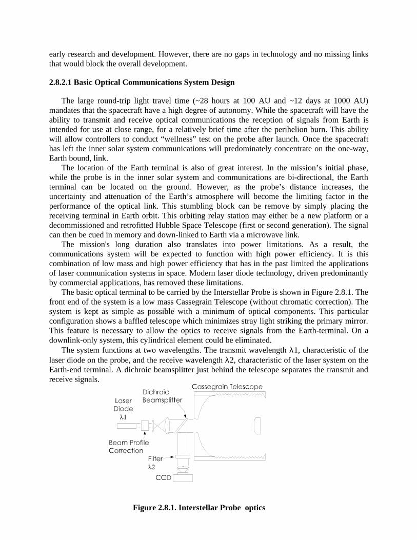
early research and development. However, there are no gaps in technology and no missing linksthat would block the overall development.
2.8.2.1 Basic Optical Communications System Design
The large round-trip light travel time (~28 hours at 100 AU and ~12 days at 1000 AU)mandates that the spacecraft have a high degree of autonomy. While the spacecraft will have theability to transmit and receive optical communications the reception of signals from Earth isintended for use at close range, for a relatively brief time after the perihelion burn. This abilitywill allow controllers to conduct “wellness” test on the probe after launch. Once the spacecrafthas left the inner solar system communications will predominately concentrate on the one-way,Earth bound, link.
The location of the Earth terminal is also of great interest. In the mission’s initial phase,while the probe is in the inner solar system and communications are bi-directional, the Earthterminal can be located on the ground. However, as the probe’s distance increases, theuncertainty and attenuation of the Earth’s atmosphere will become the limiting factor in theperformance of the optical link. This stumbling block can be remove by simply placing thereceiving terminal in Earth orbit. This orbiting relay station may either be a new platform or adecommissioned and retrofitted Hubble Space Telescope (first or second generation). The signalcan then be cued in memory and down-linked to Earth via a microwave link.
The mission's long duration also translates into power limitations. As a result, thecommunications system will be expected to function with high power efficiency. It is thiscombination of low mass and high power efficiency that has in the past limited the applicationsof laser communication systems in space. Modern laser diode technology, driven predominantlyby commercial applications, has removed these limitations.
The basic optical terminal to be carried by the Interstellar Probe is shown in Figure 2.8.1. Thefront end of the system is a low mass Cassegrain Telescope (without chromatic correction). Thesystem is kept as simple as possible with a minimum of optical components. This particularconfiguration shows a baffled telescope which minimizes stray light striking the primary mirror.This feature is necessary to allow the optics to receive signals from the Earth-terminal. On adownlink-only system, this cylindrical element could be eliminated.
The system functions at two wavelengths. The transmit wavelength λ1, characteristic of thelaser diode on the probe, and the receive wavelength λ2, characteristic of the laser system on theEarth-end terminal. A dichroic beamsplitter just behind the telescope separates the transmit andreceive signals.
Figure 2.8.1. Interstellar Probe optics
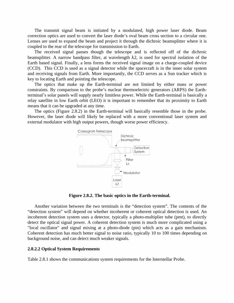
The transmit signal beam is initiated by a modulated, high power laser diode. Beamcorrection optics are used to convert the laser diode’s oval beam cross section to a circular one.Lenses are used to expand the beam and project it through the dichroic beamsplitter where it iscoupled to the rear of the telescope for transmission to Earth.
The received signal passes though the telescope and is reflected off of the dichroicbeamsplitter. A narrow bandpass filter, at wavelength λ2, is used for spectral isolation of theEarth based signal. Finally, a lens forms the received signal image on a charge-coupled device(CCD). This CCD is used as a signal detector while the spacecraft is in the inner solar systemand receiving signals from Earth. More importantly, the CCD serves as a Sun tracker which iskey to locating Earth and pointing the telescope.
The optics that make up the Earth-terminal are not limited by either mass or powerconstraints. By comparison to the probe’s nuclear thermoelectric generators (ARPS) the Earth-terminal’s solar panels will supply nearly limitless power. While the Earth-terminal is basically arelay satellite in low Earth orbit (LEO) it is important to remember that its proximity to Earthmeans that it can be upgraded at any time.
The optics (Figure 2.8.2) in the Earth-terminal will basically resemble those in the probe.However, the laser diode will likely be replaced with a more conventional laser system andexternal modulator with high output powers, though worse power efficiency.
Figure 2.8.2. The basic optics in the Earth-terminal.
Another variation between the two terminals is the “detection system”. The contents of the“detection system” will depend on whether incoherent or coherent optical detection is used. Anincoherent detection system uses a detector, typically a photo-multiplier tube (pmt), to directlydetect the optical signal power. A coherent detection system is much more complicated using a"local oscillator" and signal mixing at a photo-diode (pin) which acts as a gain mechanism.Coherent detection has much better signal to noise ratio, typically 10 to 100 times depending onbackground noise, and can detect much weaker signals.
2.8.2.2 Optical System Requirements
Table 2.8.1 shows the communications system requirements for the Interstellar Probe.
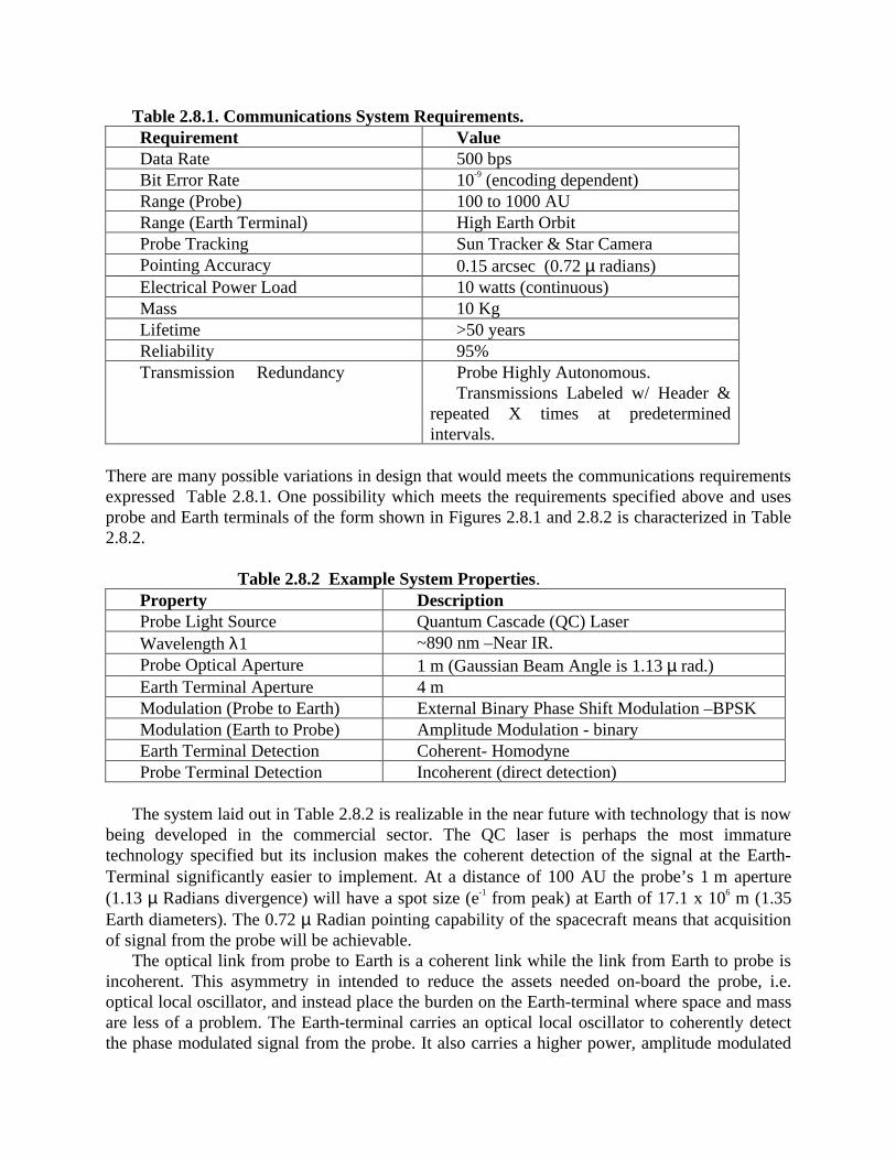
Table 2.8.1. Communications System Requirements.Requirement ValueData Rate 500 bpsBit Error Rate 10-9 (encoding dependent)Range (Probe) 100 to 1000 AURange (Earth Terminal) High Earth OrbitProbe Tracking Sun Tracker & Star CameraPointing Accuracy 0.15 arcsec (0.72 µ radians)Electrical Power Load 10 watts (continuous)Mass 10 KgLifetime >50 yearsReliability 95%Transmission Redundancy Probe Highly Autonomous.
Transmissions Labeled w/ Header &repeated X times at predeterminedintervals.
There are many possible variations in design that would meets the communications requirementsexpressed Table 2.8.1. One possibility which meets the requirements specified above and usesprobe and Earth terminals of the form shown in Figures 2.8.1 and 2.8.2 is characterized in Table2.8.2.
Table 2.8.2 Example System Properties.Property DescriptionProbe Light Source Quantum Cascade (QC) LaserWavelength λ1 ~890 nm –Near IR.Probe Optical Aperture 1 m (Gaussian Beam Angle is 1.13 µ rad.)Earth Terminal Aperture 4 mModulation (Probe to Earth) External Binary Phase Shift Modulation –BPSKModulation (Earth to Probe) Amplitude Modulation - binaryEarth Terminal Detection Coherent- HomodyneProbe Terminal Detection Incoherent (direct detection)
The system laid out in Table 2.8.2 is realizable in the near future with technology that is nowbeing developed in the commercial sector. The QC laser is perhaps the most immaturetechnology specified but its inclusion makes the coherent detection of the signal at the Earth-Terminal significantly easier to implement. At a distance of 100 AU the probe’s 1 m aperture(1.13 µ Radians divergence) will have a spot size (e-1 from peak) at Earth of 17.1 x 10⁶ m (1.35Earth diameters). The 0.72 µ Radian pointing capability of the spacecraft means that acquisitionof signal from the probe will be achievable.
The optical link from probe to Earth is a coherent link while the link from Earth to probe isincoherent. This asymmetry in intended to reduce the assets needed on-board the probe, i.e.optical local oscillator, and instead place the burden on the Earth-terminal where space and massare less of a problem. The Earth-terminal carries an optical local oscillator to coherently detectthe phase modulated signal from the probe. It also carries a higher power, amplitude modulated
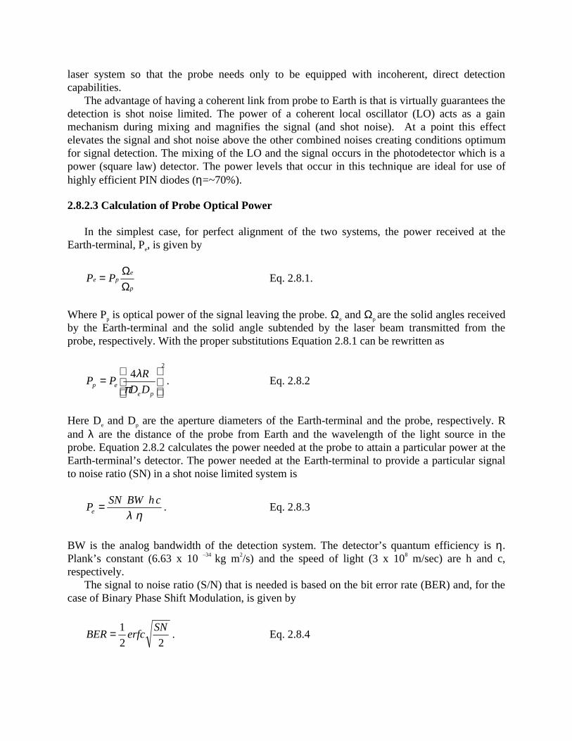
laser system so that the probe needs only to be equipped with incoherent, direct detectioncapabilities.
The advantage of having a coherent link from probe to Earth is that is virtually guarantees thedetection is shot noise limited. The power of a coherent local oscillator (LO) acts as a gainmechanism during mixing and magnifies the signal (and shot noise). At a point this effectelevates the signal and shot noise above the other combined noises creating conditions optimumfor signal detection. The mixing of the LO and the signal occurs in the photodetector which is apower (square law) detector. The power levels that occur in this technique are ideal for use ofhighly efficient PIN diodes (η=~70%).
2.8.2.3 Calculation of Probe Optical Power
In the simplest case, for perfect alignment of the two systems, the power received at theEarth-terminal, Pe, is given by
p
epe PP
ΩΩ= Eq. 2.8.1.
Where Pp is optical power of the signal leaving the probe. Ωe and Ωp are the solid angles receivedby the Earth-terminal and the solid angle subtended by the laser beam transmitted from theprobe, respectively. With the proper substitutions Equation 2.8.1 can be rewritten as
2
4
=
peep DD
RPP
πλ
. Eq. 2.8.2
Here De and Dp are the aperture diameters of the Earth-terminal and the probe, respectively. Rand λ are the distance of the probe from Earth and the wavelength of the light source in theprobe. Equation 2.8.2 calculates the power needed at the probe to attain a particular power at theEarth-terminal’s detector. The power needed at the Earth-terminal to provide a particular signalto noise ratio (SN) in a shot noise limited system is
ηλchBWSN
Pe = . Eq. 2.8.3
BW is the analog bandwidth of the detection system. The detector’s quantum efficiency is η.Plank’s constant (6.63 x 10 –34 kg m2/s) and the speed of light (3 x 10⁸ m/sec) are h and c,respectively.
The signal to noise ratio (S/N) that is needed is based on the bit error rate (BER) and, for thecase of Binary Phase Shift Modulation, is given by
22
1 SNerfcBER= . Eq. 2.8.4
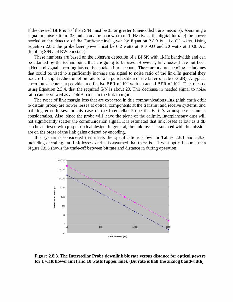
If the desired BER is 10-9 then S/N must be 35 or greater (unencoded transmissions). Assuming asignal to noise ratio of 35 and an analog bandwidth of 1kHz (twice the digital bit rate) the powerneeded at the detector of the Earth-terminal given by Equation 2.8.3 is 1.1x10⁻¹⁴ watts. UsingEquation 2.8.2 the probe laser power must be 0.2 watts at 100 AU and 20 watts at 1000 AU(holding S/N and BW constant).
These numbers are based on the coherent detection of a BPSK with 1kHz bandwidth and canbe attained by the technologies that are going to be used. However, link losses have not beenadded and signal encoding has not been taken into account. There are many encoding techniquesthat could be used to significantly increase the signal to noise ratio of the link. In general theytrade-off a slight reduction of bit rate for a large relaxation of the bit error rate (~3 dB). A typicalencoding scheme can provide an effective BER of 10-9 with an actual BER of 10-6. This means,using Equation 2.3.4, that the required S/N is about 20. This decrease in needed signal to noiseratio can be viewed as a 2.4dB bonus to the link margin.
The types of link margin loss that are expected in this communications link (high earth orbitto distant probe) are power losses at optical components at the transmit and receive systems, andpointing error losses. In this case of the Interstellar Probe the Earth’s atmosphere is not aconsideration. Also, since the probe will leave the plane of the ecliptic, interplanetary dust willnot significantly scatter the communication signal. It is estimated that link losses as low as 3 dBcan be achieved with proper optical design. In general, the link losses associated with the missionare on the order of the link gains offered by encoding.
If a system is considered that meets the specifications shown in Tables 2.8.1 and 2.8.2,including encoding and link losses, and it is assumed that there is a 1 watt optical source thenFigure 2.8.3 shows the trade-off between bit rate and distance in during operation.
0.1
1
10
100
1000
10000
100000
1000000
10000000
10 100 1000 10000
Earth Distance (AU)
Dow
nlin
k B
it R
ate
(bps
)
Figure 2.8.3. The Interstellar Probe downlink bit rate versus distance for optical powersfor 1 watt (lower line) and 10 watts (upper line). (Bit rate is half the analog bandwidth)
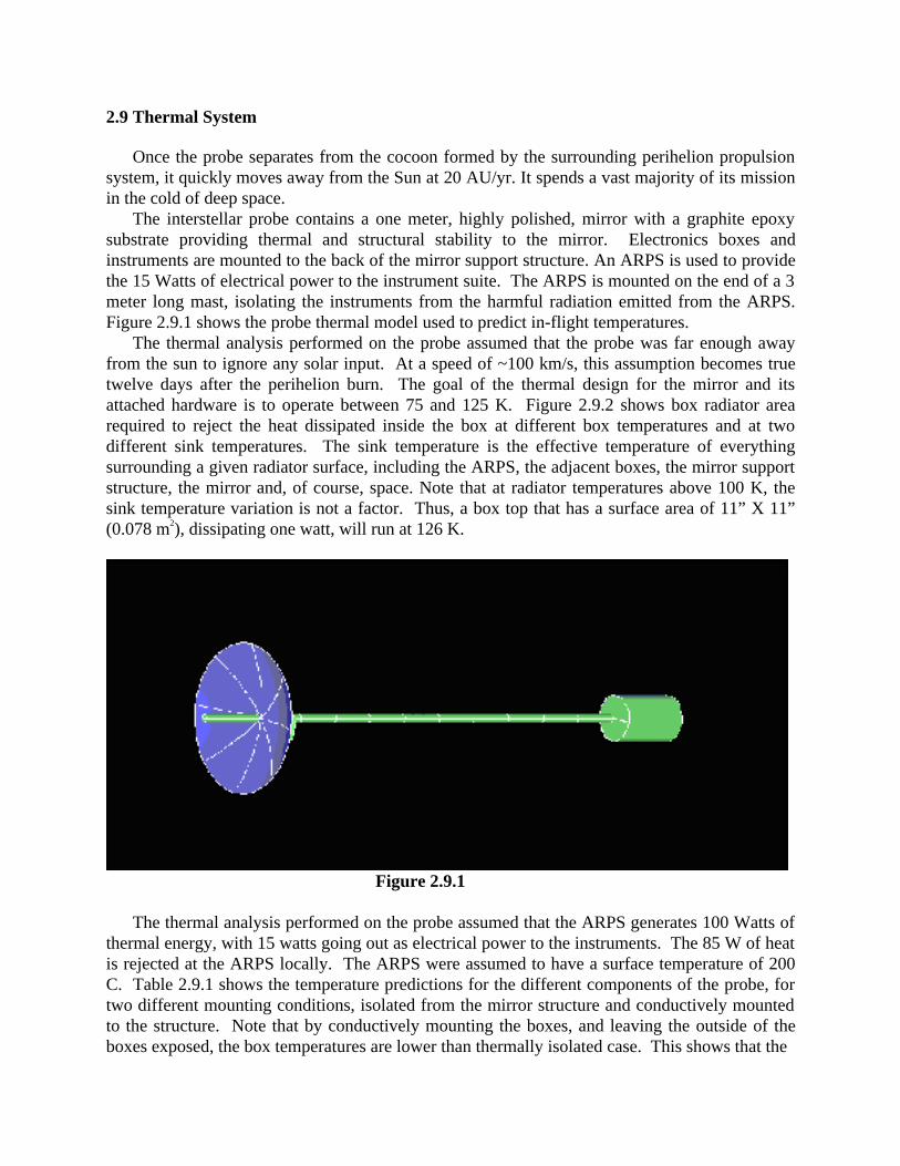
2.9 Thermal System
Once the probe separates from the cocoon formed by the surrounding perihelion propulsionsystem, it quickly moves away from the Sun at 20 AU/yr. It spends a vast majority of its missionin the cold of deep space.
The interstellar probe contains a one meter, highly polished, mirror with a graphite epoxysubstrate providing thermal and structural stability to the mirror. Electronics boxes andinstruments are mounted to the back of the mirror support structure. An ARPS is used to providethe 15 Watts of electrical power to the instrument suite. The ARPS is mounted on the end of a 3meter long mast, isolating the instruments from the harmful radiation emitted from the ARPS.Figure 2.9.1 shows the probe thermal model used to predict in-flight temperatures.
The thermal analysis performed on the probe assumed that the probe was far enough awayfrom the sun to ignore any solar input. At a speed of ~100 km/s, this assumption becomes truetwelve days after the perihelion burn. The goal of the thermal design for the mirror and itsattached hardware is to operate between 75 and 125 K. Figure 2.9.2 shows box radiator arearequired to reject the heat dissipated inside the box at different box temperatures and at twodifferent sink temperatures. The sink temperature is the effective temperature of everythingsurrounding a given radiator surface, including the ARPS, the adjacent boxes, the mirror supportstructure, the mirror and, of course, space. Note that at radiator temperatures above 100 K, thesink temperature variation is not a factor. Thus, a box top that has a surface area of 11” X 11”(0.078 m2), dissipating one watt, will run at 126 K.
Figure 2.9.1
The thermal analysis performed on the probe assumed that the ARPS generates 100 Watts ofthermal energy, with 15 watts going out as electrical power to the instruments. The 85 W of heatis rejected at the ARPS locally. The ARPS were assumed to have a surface temperature of 200C. Table 2.9.1 shows the temperature predictions for the different components of the probe, fortwo different mounting conditions, isolated from the mirror structure and conductively mountedto the structure. Note that by conductively mounting the boxes, and leaving the outside of theboxes exposed, the box temperatures are lower than thermally isolated case. This shows that the
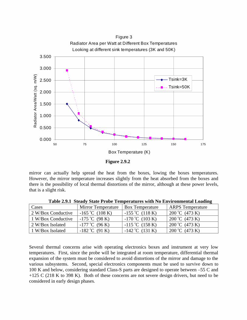
Figure 3Radiator Area per Watt at Different Box TemperaturesLooking at different sink temperatures (3K and 50K)
0.000
0.500
1.000
1.500
2.000
2.500
3.000
3.500
50 75 100 125 150 175
Box Temperature (K)
Ra
dia
tor
Are
a/W
att
(sq
. m
/W)
Tsink=3K
Tsink=50K
Figure 2.9.2
mirror can actually help spread the heat from the boxes, lowing the boxes temperatures.However, the mirror temperature increases slightly from the heat absorbed from the boxes andthere is the possibility of local thermal distortions of the mirror, although at these power levels,that is a slight risk.
Table 2.9.1 Steady State Probe Temperatures with No Environmental LoadingCases Mirror Temperature Box Temperature ARPS Temperature2 W/Box Conductive -165 oC (108 K) -155 oC (118 K) 200 oC (473 K)1 W/Box Conductive -175 oC (98 K) -170 oC (103 K) 200 oC (473 K)2 W/Box Isolated -177 oC (96 K) -115 oC (158 K) 200 oC (473 K)1 W/Box Isolated -182 oC (91 K) -142 oC (131 K) 200 oC (473 K)
Several thermal concerns arise with operating electronics boxes and instrument at very lowtemperatures. First, since the probe will be integrated at room temperature, differential thermalexpansion of the system must be considered to avoid distortions of the mirror and damage to thevarious subsystems. Second, special electronics components must be used to survive down to100 K and below, considering standard Class-S parts are designed to operate between –55 C and+125 C (218 K to 398 K). Both of these concerns are not severe design drivers, but need to beconsidered in early design phases.
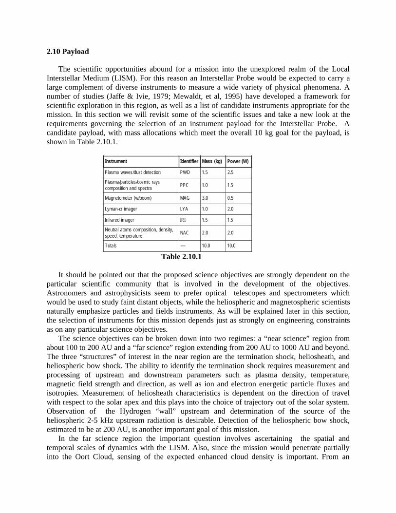
2.10 Payload
The scientific opportunities abound for a mission into the unexplored realm of the LocalInterstellar Medium (LISM). For this reason an Interstellar Probe would be expected to carry alarge complement of diverse instruments to measure a wide variety of physical phenomena. Anumber of studies (Jaffe & Ivie, 1979; Mewaldt, et al, 1995) have developed a framework forscientific exploration in this region, as well as a list of candidate instruments appropriate for themission. In this section we will revisit some of the scientific issues and take a new look at therequirements governing the selection of an instrument payload for the Interstellar Probe. Acandidate payload, with mass allocations which meet the overall 10 kg goal for the payload, isshown in Table 2.10.1.
tnemurtsnI reifitnedI )gk(ssaM )W(rewoP
noitcetedtsud/sevawamsalP DWP 5.1 5.2
syarcimsoc/selcitrap/amsalPartcepsdnanoitisopmoc
CPP 0.1 5.1
)moob/w(retemotengaM GAM 0.3 5.0
-namyL α regami AYL 0.1 0.2
regamiderarfnI IRI 5.1 5.1
,ytisned,noitisopmocsmotalartueNerutarepmet,deeps
CAN 0.2 0.2
slatoT — 0.01 0.01
Table 2.10.1
It should be pointed out that the proposed science objectives are strongly dependent on theparticular scientific community that is involved in the development of the objectives.Astronomers and astrophysicists seem to prefer optical telescopes and spectrometers whichwould be used to study faint distant objects, while the heliospheric and magnetospheric scientistsnaturally emphasize particles and fields instruments. As will be explained later in this section,the selection of instruments for this mission depends just as strongly on engineering constraintsas on any particular science objectives.
The science objectives can be broken down into two regimes: a “near science” region fromabout 100 to 200 AU and a “far science” region extending from 200 AU to 1000 AU and beyond.The three “structures” of interest in the near region are the termination shock, heliosheath, andheliospheric bow shock. The ability to identify the termination shock requires measurement andprocessing of upstream and downstream parameters such as plasma density, temperature,magnetic field strength and direction, as well as ion and electron energetic particle fluxes andisotropies. Measurement of heliosheath characteristics is dependent on the direction of travelwith respect to the solar apex and this plays into the choice of trajectory out of the solar system.Observation of the Hydrogen “wall” upstream and determination of the source of theheliospheric 2-5 kHz upstream radiation is desirable. Detection of the heliospheric bow shock,estimated to be at 200 AU, is another important goal of this mission.
In the far science region the important question involves ascertaining the spatial andtemporal scales of dynamics with the LISM. Also, since the mission would penetrate partiallyinto the Oort Cloud, sensing of the expected enhanced cloud density is important. From an
astronomical perspective, measurement of stellar and intergalactic distance scales, opticalobservation of galactic and extragalactic objects, and UV spectrometry of the galactic hydrogendistribution are valuable contributors to our understanding of the universe.
The major driving force behind instrument payload selection is mass. The Interstellar Probewas intentionally designed to be very lightweight in order to minimize the demands on thepropulsion system. The total mass of the probe is 50 kg, with 10 kg allocated for the scientificpayload. However, the scientific payload cannot be made to fit within an arbitrarily tight massallocation simply to meet the design constraints of the propulsion system. The mass allocationfor the payload must be reasonable. It is believed that the mass allocation of 10 kg is reasonablebecause a number of technological advances, as well as innovative system level architecturalchoices, makes it possible for the suggested complement of roughly ten scientific instruments tofit within the allotted mass.
The architecture of the instrument payload is novel in several respects. First of all, none ofthe instruments have their own processor, but instead rely on a common bank of processorswhich support all operations performed on the probe. This distributed, self healing system isdiscussed in section 2.7.2 of this report. Secondly, the migration of functions from the hardwareto the software realm occurs much earlier in the signal chain than in today’s instruments. Ofcourse, this trend toward implementing functions in software is not new, but development effortsbeing expended at this time will enable the software to be inserted at a point just after theconversion of the raw sensor signal to the digital world. As an example of this type ofmethodology which is currently being implemented at the Applied Physics Lab, consider anenergetic particle instrument which measures energy using solid state detectors and particlevelocity using a time-of-flight sensor head. Typically, a substantial amount of electronics isrequired (often a number of boards weighing a kilogram or more) to amplify and condition theenergy signal(s), amplify and detect the timing signals, measure the time-of-flight, performcoincidence timing as well as valid event determination.
Recent advances in microelectronics have put a charge amplifier, shaping circuit,discriminator and A/D converter on a single small integrated circuit. Similarly, a TOF chip hasbeen developed which contains dual constant fraction discriminators and a time-to-digitalconverter. It directly accepts the timing signals from the anodes in the TOF head. Hence, withminimal mass and power the detector signals are converted into the digital domain. However, thecoincidence, binning, and valid event logic still consume a fair amount of electronics boardspace. This electronics is eliminated by simply applying digital timetags to all the various values(e.g energy and TOF) acquired by the instrument. The values, with their separate timetags, arefed directly into a high speed processor, where realtime coincidence determination and validevent selection are performed completely in software. Although software development iscomplex in its own right, it does mean that the mass of the sensor is reduced, that electronicsparts which are subject to radiation are minimized, and that maximum flexibility is obtained.Although it may be argued that the electronic effort has simply been moved from dedicatedhardware into other electronic parts (the bank of central processors), the processors are muchmore robust due to their high redundancy (many interlinked processors where each individualprocessor has the computing power to singly handle all the Interstellar Probe tasks, if required)and self healing capability, which involves sophisticated health monitoring and reconfigurability.
Each instrument communicates with the bank of central processors via a wireless high speeddata link. In a sense, the entire spacecraft is inter-communicating via a type of cellular telephonesystem, where each instrument broadcasts on its own frequency. Each central processor knows
which instrument is it’s responsibility, so it tunes into the appropriate frequency and collects andprocesses the data from the correct sensor. This wireless link eliminates most of the heavyharness which is required on conventional spacecraft for connection of the instruments to thecommand and data handling subsystem (C&DH).
Another key advantage to this architecture is in the increased ability to make the remaininginstrument systems robust and redundant. Instruments have certainly failed on past spacemissions and often this failure is due to the failure of an individual detector, a power supply, ordue to a latch-up condition in the electronics from radiation damage. In the past it has beendifficult to make instruments redundant since the number of parts to duplicate has beensubstantial in both mass and cost. With the instrument architecture described here, it becomesmore reasonable to make portions of the instrument redundant since the amount and mass ofelectronics in the sensor head has been minimized. For example, it may be possible for a solidstate detector and its associated “energy chip” to be made redundant with very little penalty inmass or design complexity.
In the following sections we examine a small subset of the possible instruments thatwould be appropriate for the Interstellar Probe. However, it must be stated that an enormouseffort is currently being expended by scientists and engineers at various institutions to improvethe sensors for all the candidate instruments. To a certain extent, those investigators whoseinstruments are chosen to fly will likely have been the individuals who were most successful inminiaturizing the sensor heads while still maintaining significant science gathering capability.
2.10.1 Magnetometer
The Interstellar Probe has been designed with a pair of booms for magnetometer sensors anda pair of booms for electric field measurements. The booms are mounted to the edge of theoptical communications dish and are stowed alongside the probe’s central mast when the probe isenclosed in the propulsion system. When the probe is pushed out of its “cocoon” after theperihelion burn maneuver all four booms swing out and lock into position.
Significant progress has been made in recent years with both magnetometer sensors andfront-end electronics. Currently available fluxgate sensors have sensitivities adequate for theweak fields expected in the LISM. Their mass is around 250 gms and recent developmentsindicate that the sensor mass can be reduced to nearly 100 gms with no loss in sensitivity. Also,an alternative sensor is being developed using MEMS technology which uses an ultra-miniatureoscillating cantilever. At present, their sensitivity does not match that of the fluxgate sensors andthis limitation is a primary area of current research. The front-end electronics are beingminimized in size by the use of chip-on-board (COB) fabrication techniques, as well as bymoving some of the filtering operations from onboard passive components to digital filtering insoftware. Delta sigma converters are also undergoing significant improvement. For example,Analog Devices now has an A/D converter with three differential input channels (ideal for 3 axismagnetometers), programmable gain amplifier (useful for range changing) and 16 bit accuracythat consumes only 1 milliwatt.
One of the key aspects to successful operation of the scientific payload on the InterstellarProbe mission is data reduction. Because of the large travel distances involved and the need tokeep the communication system small, the communication downlink rate is quite low.Transmissions only occur once a week and the total amount of bits allocated to a particularinstrument is minimal. Lossless and lossy compression systems help somewhat, but it is
necessary to perform a certain amount of high level data analysis onboard in order to distill thelarge amount of data down to a quantity that can fit into the telemetry allocation. Themagnetometer instrument, which typically provides continuous time series data of the magneticfield strength, must convert the data to vector quantities and then heavily average the data(perhaps over periods of several hours). This averaged data is useful for gross tracking ofmagnetic field variations. However, the processing software would also be capable of identifyingregions of greater interest which had occurred during the data acquisition period and save thatinformation at a higher time resolution. The magnetometer’s telemetry allocation would be ableto accommodate transmission of a few of these “zoomed in” regions during the regularcommunication period.
2.10.2 Plasma/Radio Wave Experiments
A pair of opposed booms are available for placement of electric field sensors. Compared tomost particles and fields instruments, the amount of front-end analog electronics that is needed isactually quite minimal. Typically only small, low-noise differential amplifiers are needed at thereceiver to amplify the signals to a level where digitization is possible. After that point, plasmawave sensors have historically used a significant amount of specialized dedicated hardware inorder to perform high speed narrow band swept frequency analysis as well as Fourier (FFT)analysis. Since the interstellar probe will have an extremely powerful bank of processors, it willbe possible to perform virtually all this analysis in software. Hence, the significant amount ofmass and power normally required by these instrument will be significantly reduced.
As in the case of the magnetometer instrument, the plasma wave instrument producescontinuous streams of time series data which are usually converted into the frequency domain.The magnitude and phase results are then usually log compressed before being telemetered. Thisdata would also have to be severely time averaged. However, higher level processing would beable to detect interesting structure in the data and save that portion of the data at a higherresolution for subsequent transmission to the ground.
2.10.3 Neutrals, Plasma, and Suprathermal Dynamics and Composition
The number of sensor heads required to cover the wide range of particles energies, chargestates, ion species, and electrons populations expected during the mission is substantial. Scienceworking groups have studied the instrumentation required and one team in particular hasdeveloped an instrument suite which measures Neutrals from 10eV to 6KeV, Plasma Ions from 0to 10 KeV/q , Plasma Electrons from 10ev to 800eV, and performs composition and charge statemeasurements from 0 to 1 MeV/q. The number of sensor heads in this instrument package isseven, which clearly would exceed the mass allocation for the entire science payload. Many ofthese sensor heads are most needed for the “near” science region. If an Interstellar ProbePrecursor mission (to 200 AU) or Interstellar Probe Pathfinder (remote sensing from within thesolar system) are undertaken prior to the Interstellar Explorer mission, then some of the “near”region questions would already be answered and the number of sensor heads could be paireddown for the Interstellar Probe.
A minimum complement that is needed for the LISM would consist of a low energy NeutralGas sensor head covering the 10eV to 1000eV range, with composition capability beingdesirable, and high resolution ion and electron plasma sensors covering 0-10KeV/q and 10eV-
800eV, respectively. Neutral Gas analyzers have taken several forms; the simplest and lightestunits cannot do composition, while complicated and heavy charge conversion systems can docomposition. Unlike Plasma Wave instruments, where the sensor is relatively straightforward butthe electronics are complicated, the neutral gas sensors have sensor heads which are difficult toreduce in mass, while the electronics are quite capable of being miniaturized.
Extremely elegant designs for ion and electron plasma heads have been developed byinvestigators in Germany and the United States during the past few years. The FIPS ion plasmahead weighs only 700 gms while the MAREMF electron head weighs 450 gms. These heads areespecially suited for placement on spinning spacecraft and provide nearly 4 pi coverage. Theprocessing for these heads is straightforward and has been determined to require about 5 MIPs ofcomputing power for full computation of plasma parameters. Hence, a portion of the computingpower in a single Interstellar Probe processor module will suffice to perform all processing forthese heads.
Again, due to the limited downlink bandwidth available, the data from these instruments,such as sectored M/q distributions and velocity measurements, must be heavily time averaged.Again, onboard algorithms that identify areas of scientific interest can be zoomed in on and alimited amount of high resolution data can also be downlinked. More advanced processing couldconceivably involve generating composition and/or charge state plots which are overlaid overstored templates which represent a scientists prediction of various predicted physical phenomena(quiet times or shock profiles). If the plot representing the acquired data matches the template,then on-board decisions could be made to simply send down simple “condition indicators” (e.g.all quiet), rather then simply time series data. The condition indicator would remain valid untilthe data matched a new condition, at which point the condition indicator would be changed and ,at that point, some representative data could be included in the telemetry stream.
3. Extension of the Mission to Longer Durations
The Interstellar Explorer mission provides a significant science return, performing initialinvestigations of the totally unexplored realm of Interstellar Space, as well as the interestingregions at the boundary of our solar system. Additionally, a number of engineering milestoneswill be achieved. Perhaps the most important milestone is enhanced mission duration, since it isclear that some future missions, such as those that journey to the stars, will be more than an orderof magnitude longer in duration. Indeed, this mission is the first small step toward realisticallyachieving a true interstellar capability.
There are two keys aspects associated with performing extremely long duration missions.The first involves the reality of life on Earth. Wars and other extremely disruptive events oftenoccur, making it difficult to maintain any infrastructure for periods longer than several hundredyears. However, there are a few buildings that have been continually maintained for over athousand years, so maintaining contact with a probe travelling to the nearest stars may bepossible for that length of time. In order to maximize the probability of continued contact, it isimportant to distribute the data gathering knowledge among as many diverse peoples as possible.If the entire data gathering equipment and personnel are centralized, then a single catastrophe canwipe out all knowledge of the mission.
The second key aspect to a long duration mission is the selection of Interstellar Probematerials. Even though clever architectures can make systems robust and fault tolerant, long termaging processes can reduce virtually any system to dust over time. A number of previous
missions, such as the Long Duration Exposure Facility (LDEF), have shown that even the lowdensities of particles in space can slowly degrade space materials. Hence, the choice of materialsis extremely important for missions with durations longer than 50 years. One example is in thearea of microcircuits, which are manufactured using silicon and other materials. These device aresubject to electromigration, which eventually may cause the devices to fail. The feature size ofthe device, the current densities, as well as the interconnection material, are factors in the rate ofelectromigration. It may be necessary to use integrated circuits with large feature sizes, which arein some ways considered old technology, in order to achieve long life. However, a number ofrecent developments, such as ultra low power circuits (which have very low current densities),and the transition to copper and tungsten interconnects on sapphire substrates (instead ofaluminum on silicon), may significantly improve the ultimate lifetimes of modern electronics.
4. Conclusions
We have provided a first-order cut at many of the engineering realities associated withsending a small interstellar precursor mission out of the solar system at a high speed. Theprimary engineering concern remains primarily propulsion, but we have also identified otherconstraints and interactions that need to be approached in a systems manner:
To maximize the asymptotic escape speed from the Sun, a target direction near the plane ofthe ecliptic must be chosen; although the constraints may not be as great, this is probably thecase for low-thrust schemes as well, e.g., NEP and solar-sail propulsion.
If a Jupiter flyby is required to reach the Sun to do a perihelion maneuver to boost the escapespeed, then additional planetary flybys will not help to ease the mass constraints of a givenlaunch vehicle; they over-constrain the trajectory design problem.
Some form of the indirect launch mode - allowing an additional stage for the launch vehicle -is doable and probably required to launch a reasonably sized probe first to Jupiter and then to theSun for the perihelion maneuver.
The Orion concept, per se, simply will not work with the limited mass available on a probesuch as this. Fission may well provide the key element for the perihelion propulsion, but only ina pulsed mode with extremely-low fission yields per pulse.
Solar thermal propulsion and a near-Sun maneuver seem to be "made for each other";problems that require more study are heat transfer to the working fuel and how high a specificimpulse can be obtained. Liquid hydrogen (and its dissociation at very high temperatures)appears to offer the best solution, but suffers from the mass associated with storing a cryogen forover 3 years in deep space. Ammonia offers an excellent storage solution, but appears to limit thespecific impulse. More study of the systems aspect is required with emphasis on the mass of theoverall propulsion system hardware plus fuel.
Thermal shielding of the probe near the Sun is not an issue as long as the probe is notspinning and can actively point a Sun-shield toward the Sun during the perihelion passage. Theumbra (shadow) of the shield does drive the mechanical configuration of the probe during theperihelion passage segment of the mission.
Data downlink, attitude control and knowledge, and communications means and power areall intimately linked; the data downlink requirements tend to drive the entire probe architecturefor the interstellar flight configuration. Implementation is simplified by using "fire and forget"operations - the probe requires an autonomous and self-healing character so that uplinks are nolonger necessary following final departure outbound from the inner solar system.
Low-power operations will help to ensure longevity of the probe while minimizing therequired mass for a radioisotope power system. Isotopes longer lived than plutonium that havelower power densities offer engineering challenges in providing efficient production ofelectricity; the subject requires further study.
Continued miniaturization of scientific instrument electronics and detectors is required toimplement a mission with a reasonable science return - the reason for the mission in the firstplace.
The concept we are pursuing for a realistic Interstellar Explorer has applicability to anyrobotic interstellar precursor mission. In addition, this concept offers potential advantages - aswell as an alternative - to low thrust probes. Such systems require a great deal of control for theirprimary propulsion system. The approach here has only a few, short-duration critical operationalperiods. From a systems point of view this approach offers distinct advantages.
5. Acknowledgements
Many individuals contributed to this report, either by writing various subsections, or byoffering ideas, suggestions and technical expertise. Those who wrote sections of this report areBruce Williams (thermal), Dave Haley (attitude control), Jim McAdams (trajectory design), KenHeeres (autonomous operation), Marty Fraeman (low power electronics), Bob Bokulic(microwave communications), Doug Oursler (optical communications), and Bruce Andrews(system engineering). Useful discussions occurred with Paul Panneton, Judi Von Mehlem, RobGold, Larry Mosher, Ed Reynolds, Bob Farquhar, Dave Sussman ,Dave Dunham, Ed Roelof, andBob Jenkins of APL and with Roger Westgate of the JHU School of Engineering, Dean Lester ofThiokol Corporation, Dean Read at Lockheed-Martin and Dan Doughty at Sandia NationalLaboratories.
6. References
Ackeret, J., Zur Theorie der Raketen, Helv. Phys. Acta, April,1946; J. Brit. Int. Soc., 6, 116-123,1947.
Ackeret, J., (English translation) On the theory of rockets, J. Brit. Int. Soc., 6, 116-123, 1947.Allen, C. W., Astrophysical Quantities, 3rd ed., London, The Athlone Press, 1973.Bhaskaran, S., The application of noncoherent Doppler data types for deep space navigation,
Telecommunications and Data Acquisition Progress Report 42-121, JPL, May 15, 1995.Bond, A., et al., Project Daedalus, J. Brit. Int. Soc. Suppl., 1978.Burr J. B. and A. M. Peterson, “Ultra Low Power CMOS Technology,” NASA VLSI Design
Symposium., 1991, pp. 4.2.1-4.2.13.Burr J. B. , “Cryogenic Ultra Low Power CMOS,” IEEE Int. Symp. Low Power Electronics,
1995, p9.4.Bussard, R. W., Galactic matter and interstellar flight, Astron. Acta, 6, 179-194, 1960.Case, K. M. and P. F. Zweifel, Linear Transport Theory, Addison-Wesley Publishing Company,
Reading, MA, 1967Cassenti, B. N., Robotic interstellar missions and advanced nuclear propulsion, J. Brit. Int. Soc.,
49, 357-360, 1996.

Chandrakassan A., S. Sheng, and R. Brodersen, “Low Power CMOS Digital Design,” IEEEJournal of Solid State Circuits, vol. SC-27, no. 4, pp 1082-1087, April, 1992.
Cochran, T. B., W. M. Arkin, and M. M. Hoenig, Nuclear Weapons Databook: Volume I U.S.Nuclear Forces and Capabilities, Ballinger Publishing Co., Cambridge, Mass., 1984.
Deininger, W. D., and R. J. Vondra, Spacecraft and mission design for the SP-100 flightexperiment, J. Brit. Int. Soc., 44, 217-228, 1991.
Dole, S. H., Habitable Planets for Man, Blaisdell Publishing Company, New York, 1964.Dyson, F. J., Death of a project, Science, 149, 141-144, 1965.Dyson, F. J., Interstellar transport, Phys. Today, , 41-45, 1968.Ehricke, K. A., Saturn-Jupiter rebound, J. Brit. Int. Soc., 25, 561-571, 1972.Farquhar, R. W., and D. W. Dunham, Indirect launch mode: A new launch technique for
interplanetary missions, IAA paper L98-0901, April 1998, in press Acta Astronautica, 1999.Forward, R. L., Ad astra!, J. Brit. Int. Soc., 49, 23-32, 1996.Frisch, P. C., G-star astropauses: A test for interstellar pressure, Astrophys. J., 407, 198-206,
1993.Gray, D. F., and S. L. Baliunas, Magnetic activity variations of e Eridani, Astrophys. J., 441,
436-442, 1995.Gurnett, D. A., W. S. Kurth, S. C. Allendorf, and R. L. Poynter, Radio emission from the
heliopause triggered by an interplanetary shock, Science, 262, 199, 1993.Hammerling, P. and J. L. Remo, NEO interaction with nuclear radiation, Acta Astron., 36, 337-
346, 1995.Holzer, T. E., et al. The Interstellar Probe: Scientific objectives for a Frontier mission to the
heliospheric boundary and interstellar space, 1990.Hyde, R., L. Wood, and J. Nuckolls, Prospects for rocket propulsion with laser-induced fusion
miccroexplosions, AIAA paper AIAA 71-1063, 1972.Jaffe, L. D. and C. V. Ivie, Science aspects of a mission beyond the planets, Icarus, 39, 486-494,
1979.Jaffe, L. D. and H. N. Norton, A prelude to interstellar flight, Astro. Aero., 18, 38-44, 1980.Jones, R. M. and C. G. Sauer, Nuclear electric propulsion missions, J. Brit. Int. Soc., 36, 395-
400, 1984.Laming, J. M., J. J. Drake, and K. G. Widing, Stellar coronal abundances. IV. Evidence of the
FIP effect in the corona of Eridani Astrophys. J., 462, 948-959, 1996.Lawton, A. T., and P. Wright, The search for companions to Epsilon Eridani, J. Brit. Int. Soc.,
43, 556-558, 1990.Linsky, J. L., and B. E. Wood, The α Centauri line of sight: D/H ratio, physical properties of
local interstellar gas, and measurement of heated hydrogen (the "hydrogen wall") near theheliopause, Astrophys. J., 463, 254-270, 1996.
Logan, J., The critical mass, American Scientist, 84, 263-277, 1996.Martin, A. R., and A. Bond, Project Daedalus: The propulsion system, J. Brit. Int. Soc. Suppl.,
S44-S62, 1978.Mauk, B. H., P. F. Bythrow, N. A. Gatsonis, and R. L. McNutt, Jr., Science plan for the nuclear
electric space test program (NEPSTP), AIAA-93-1895, 1993.McNutt, R. L., Jr., A. J. Lazarus, J. W. Belcher, J. Lyon, C. C. Goodrich and R. Kulkarni, The
distance to the heliospheric VLF mission region, Adv. Space Res., 16(9), 303-306, 1995.McNutt, R. L., Jr., R. E. Gold, E. C. Roelof, L. J. Zanetti, E. L. Reynolds, R. W. Farquhar, D. A.
Gurnett, and W. S. Kurth, A sole/ad astra: From the Sun to the stars, J. Brit. Int. Soc., 50,

463-474, 1996.Meissinger, H. F., S. Dawson, and J. R. Wertz, A low-cost launch mode for high-C3
interplanetary missions, AAS paper AAS 97-711, 1997.Mewaldt, R. A., J. Kangas, S. J. Kerridge, and M. Neugebauer, A small interstellar probe to the
heliospheric boundary and interstellar space, Acta Astron., 35, Suppl., 267-276, 1995.Noble, R. J., Radioisotope electric propulsion for robotic science missions to near-interstellar
space, J. Brit. Int. Soc., 49, 322-328, 1996.Nodland, B., and J. P. Ralston, Indication of anisotropy in electromagnetic propagation over
cosmological distances, Phys. Rev. Lett., 78, 3043-3046, 1997.Rand, R. J., and A. G. Lyne, New rotation measures of distant pulsars in the inner galaxy and
magnetic field reversals, Mon. Not. R. Astron. Soc., 268, 497-505, 1994.Sänger, E., Some optical and kinematical effects in interstellar astronautics, J. Brit. Int. Soc., 18,
273-277, 1961-2.Sagan, C., Direct contact among galactic civilizations by relativistic interstellar spaceflight,
Planet. Space Sci., 11, 485-498, 1963.Sagan, C., and I. S. Shklovskii, Intelligent Life in the Universe, Dell Publishing Co., Inc., New
York, 1966.Schmitt, J. H. M. M., J. J. Drake, R. A. Stern, and B. M. Haisch, The extreme-ultraviolet
spectrum of the nearby K dwarf • Eridani, Astrophys. J., 457, 882-891, 1996. Schramm, D. N., and M. S. Turner, Big-bang nucleosynthesis enters the precision era, Rev. Mod.
Phys., 70, 303-318, 1998.Serber. R., The Los Alamos Primer, University of California Press, Berkeley, 1992. Shepherd, L. R., Interstellar flight, J. Brit. Int. Soc., 11, 149-167, 1952.Space Physics Strategy-Implementation Study, Vol. 1: Goals, Objectives, Strategy, 2nd ed., and
Vol. 2: Program Plan, April, 1991.Stone, E. C. and E. D. Miner, The Voyager 2 encounter with the Neptune system, Science, 246,
1417-1421, 1989.Stone, E. C., A. C. Cummings, and W. R. Weber, The distance to the solar wind termination
shock in 1993 and 1994 from observations of anomalous cosmic rays, J. Geophys. Res., 101,11017-11025, 1996.
Wallace, R. A., Precursor missions to interstellar exploration, IEEE Aerospace Conference,March 6-13, 1999, Snowmass at Aspen, Colorado, IEEE Aerospace Conference Paper No.114, 1999.
Williams, S. N., and V. Coverstone-Carroll, Benefits of solar electric propulsion for the nextgeneration of planetary exploration missions, J. Astron. Sci., 45, 143-159, 1997.
Winterberg, F., The Physical Principles of Thermonuclear Explosive Devices, Fusion EnergyFoundation, 1981.
von Hoerner, S., The general limits of space travel, Science, 137, 18-23, 1962.Zubrin, R., Nuclear salt water rockets: High thrust at 10,000 sec Isp, J. Brit. Int. Soc., 44, 371-376, 1991.