Embed Size (px)
Citation preview

Bio-Pharm
1915 S. Stoughton Rd., Madison, WI 53716 (o) 800-356-3300 (f) 608-222-5348 sanimatic.com
Cleaning Confidence
PharmaCabTM SP Series GMP Cabinet Washer
Technical Datasheet

sanimatic.com 2
Model Number Key
1 3 5 7 92 4 6 8 10 11 12 13 14 15 16 17 18 19
Example Model #: SP333-11R0E-GS0-AE-00000C
1–5 Chamber Model
SP333 34" W x 34" D x 40" H
SP443 48" W x 48" D x 40" H
SP444 48" W x 52" D x 48" H
6 Door Configuration
1 Single Door (Standard)
2 Double Door
7 System Configuration
1 Right Handed (Standard)
2 Left Handed
8 Final Rinse Type
R Recirculated Final Rinse (Standard)
S Single Pass Final Rinse
9 Dryer System
0 No Dryer System (Standard)
1 Dryer System - No Service Panels
2 Dryer System - Front Service Panels (Single Door)
3 Dryer System - Front & Back Service Panels (Double Door)
10 Recirculated Heating
E Electric (Standard)
S Steam
11 Supply Pressure Monitoring
G Pressure Gauge (Standard)
T Pressure Transmitter
12 Supply Flow Monitoring
S Flow Switch (Standard)
M Flow Meter
13 Conductivity Monitoring
0 Wash & Rinse Conductivity Control (Standard)
14 Controls
A Allen-Bradley Controls Package (Standard)
15 Reporting
E Electronic Data (Standard)
P Report Ticket Printer
16 Water Addition
0 Dual Water Ports (Standard)
1 Dual Water Ports with (1) Pneumatic Valve
2 Dual Water Ports with (2) Pneumatic Valves
17 Chemical Addition
0 Dual Chemical Ports (Standard)
1 Single Chemical Delivery
2 Dual Chemical Delivery
18 Drain Type
0 Gravity Drain (Standard)
1 Drain Pump
19 Drain Cooling
0 No Drain Cooling Valve (Standard)
1 Drain Cooling Valve
20 Sampling Method
0 No Sample Station (Standard)
1 Sample Station - Single Door
2 Sample Station - Unload Side (Double Door)
3 Sample Station - Load Side (Double Door)
20 21
C

sanimatic.com 3TD-0002.1
Table of Contents1. Introduction . . . . . . . . . . . . . . . . . . . . . . . . . . . . . . . . . . . . . . . . . . 5
2. Applications . . . . . . . . . . . . . . . . . . . . . . . . . . . . . . . . . . . . . . . . . 5
3. Construction . . . . . . . . . . . . . . . . . . . . . . . . . . . . . . . . . . . . . . . . . 5
3.1 Certifications and Classifications . . . . . . . . . . . . . . . . . . . . . . . . . . 5
3.2 Structural Framing . . . . . . . . . . . . . . . . . . . . . . . . . . . . . . . . . . . 5
3.3 Hygienic Piping . . . . . . . . . . . . . . . . . . . . . . . . . . . . . . . . . . . . . 5
3.4 Service Panels . . . . . . . . . . . . . . . . . . . . . . . . . . . . . . . . . . . . . 6
3.5 Electrical Conduit . . . . . . . . . . . . . . . . . . . . . . . . . . . . . . . . . . . 6
3.6 Pneumatics . . . . . . . . . . . . . . . . . . . . . . . . . . . . . . . . . . . . . . . 6
3.7 Instrument Tags . . . . . . . . . . . . . . . . . . . . . . . . . . . . . . . . . . . . 6
4. Utility Requirements . . . . . . . . . . . . . . . . . . . . . . . . . . . . . . . . . . . . 6
5. Physical Size & Layout . . . . . . . . . . . . . . . . . . . . . . . . . . . . . . . . . . 7
6. Component Manufacturers . . . . . . . . . . . . . . . . . . . . . . . . . . . . . . . . 8
7. Equipment Description . . . . . . . . . . . . . . . . . . . . . . . . . . . . . . . . . . 9
7.1 Chamber . . . . . . . . . . . . . . . . . . . . . . . . . . . . . . . . . . . . . . . . . 9
7.2 Circulation System . . . . . . . . . . . . . . . . . . . . . . . . . . . . . . . . . . . 10
7.3 Heating System . . . . . . . . . . . . . . . . . . . . . . . . . . . . . . . . . . . . 10
7.4 Control System . . . . . . . . . . . . . . . . . . . . . . . . . . . . . . . . . . . . . 10
7.4.1 Low Voltage Control Panel . . . . . . . . . . . . . . . . . . . . . . . . . . . 10
7.4.2 Pneumatics. . . . . . . . . . . . . . . . . . . . . . . . . . . . . . . . . . . . 11
7.4.3 High Voltage Control Panel . . . . . . . . . . . . . . . . . . . . . . . . . . 11
7.4.4 Load Side Operator Interface . . . . . . . . . . . . . . . . . . . . . . . . . 11
8. Equipment Operation . . . . . . . . . . . . . . . . . . . . . . . . . . . . . . . . . . . 11
8.1 Loading and Unloading Operation . . . . . . . . . . . . . . . . . . . . . . . . . 11
8.2 Cleaning Cycle . . . . . . . . . . . . . . . . . . . . . . . . . . . . . . . . . . . . . 11
8.3 Controls . . . . . . . . . . . . . . . . . . . . . . . . . . . . . . . . . . . . . . . . . 12
8.4 Automation Interface . . . . . . . . . . . . . . . . . . . . . . . . . . . . . . . . . 12
8.5 Reporting . . . . . . . . . . . . . . . . . . . . . . . . . . . . . . . . . . . . . . . . 12
9. Documentation . . . . . . . . . . . . . . . . . . . . . . . . . . . . . . . . . . . . . . . 12
10. Product Options . . . . . . . . . . . . . . . . . . . . . . . . . . . . . . . . . . . . . . 13
10.1 Door Configuration . . . . . . . . . . . . . . . . . . . . . . . . . . . . . . . . . . 13
10.2 System Configuration . . . . . . . . . . . . . . . . . . . . . . . . . . . . . . . . 13
10.3 Final Rinse Type . . . . . . . . . . . . . . . . . . . . . . . . . . . . . . . . . . . 13
10.4 Dryer System . . . . . . . . . . . . . . . . . . . . . . . . . . . . . . . . . . . . . 14
10.5 Recirculated Heating . . . . . . . . . . . . . . . . . . . . . . . . . . . . . . . . . 15
10.6 Supply Pressure Monitoring . . . . . . . . . . . . . . . . . . . . . . . . . . . . 15
10.7 Supply Flow Monitoring . . . . . . . . . . . . . . . . . . . . . . . . . . . . . . . 16
10.8 Reporting . . . . . . . . . . . . . . . . . . . . . . . . . . . . . . . . . . . . . . . 16
10.9 Water Addition. . . . . . . . . . . . . . . . . . . . . . . . . . . . . . . . . . . . . 16

sanimatic.com 4TD-0002.1
10.10 Chemical Addition . . . . . . . . . . . . . . . . . . . . . . . . . . . . . . . . . . 16
10.11 Drain Type . . . . . . . . . . . . . . . . . . . . . . . . . . . . . . . . . . . . . . . 16
10.12 Drain Cooling . . . . . . . . . . . . . . . . . . . . . . . . . . . . . . . . . . . . . 16
10.13 Sampling Method . . . . . . . . . . . . . . . . . . . . . . . . . . . . . . . . . . 17
11. Accessories . . . . . . . . . . . . . . . . . . . . . . . . . . . . . . . . . . . . . . . . . 17
11.1 Accessory Category – Racks . . . . . . . . . . . . . . . . . . . . . . . . . . . . . 17
11.1.1 Rack – Low Load Density (Budgetary) . . . . . . . . . . . . . . . . . . . . 18
11.1.2 Rack – Medium Load Density (Budgetary) . . . . . . . . . . . . . . . . . 18
11.1.3 Rack – High Load Density (Budgetary) . . . . . . . . . . . . . . . . . . . 18
11.1.4 Riboflavin Test – Rack . . . . . . . . . . . . . . . . . . . . . . . . . . . . . 18
11.1.5 Passivation – Rack . . . . . . . . . . . . . . . . . . . . . . . . . . . . . . . 18
11.1.6 Borescope Inspection Video – Rack . . . . . . . . . . . . . . . . . . . . . 18
11.1.7 Transfer Cart – SP333 . . . . . . . . . . . . . . . . . . . . . . . . . . . . . 19
11.1.8 Transfer Cart – SP443 . . . . . . . . . . . . . . . . . . . . . . . . . . . . . 19
11.1.9 Transfer Cart – SP444 . . . . . . . . . . . . . . . . . . . . . . . . . . . . . 19
11.1.10 Part 3D Modeling – Design Cost (per Part) . . . . . . . . . . . . . . . . . 19
11.1.11 Part 3D Modeling – Trip (Budgetary) . . . . . . . . . . . . . . . . . . . . . 19
11.2 Accessory Category – System Additions . . . . . . . . . . . . . . . . . . . . . 20
11.2.1 Passivation – System . . . . . . . . . . . . . . . . . . . . . . . . . . . . . . 20
11.2.2 Hydrostatic Test . . . . . . . . . . . . . . . . . . . . . . . . . . . . . . . . 20
11.2.3 Riboflavin Test – Chamber . . . . . . . . . . . . . . . . . . . . . . . . . . 20
11.2.4 Riboflavin Test – Rinse Tank . . . . . . . . . . . . . . . . . . . . . . . . . 20
11.2.5 Borescope Inspection Video - System . . . . . . . . . . . . . . . . . . . 20
11.2.6 Seismic Zone Anchorage Calculations . . . . . . . . . . . . . . . . . . . 20
11.2.7 Barrier Flanges . . . . . . . . . . . . . . . . . . . . . . . . . . . . . . . . . 20
11.3. Accessory Category – Documentation . . . . . . . . . . . . . . . . . . . . . . 21
11.3.1 Functional Specification (FS) . . . . . . . . . . . . . . . . . . . . . . . . . 21
11.3.2 Configuration Specification (CS) . . . . . . . . . . . . . . . . . . . . . . . 21
11.3.3 Factory Acceptance Test (FAT) . . . . . . . . . . . . . . . . . . . . . . . 21
11.3.4 Site Acceptance Test (SAT) . . . . . . . . . . . . . . . . . . . . . . . . . . 21
11.3.5 Installation Qualification / Operational Qualification (IQ/OQ) . . . . . . . 21
11.3.6 Instrument Data Sheets . . . . . . . . . . . . . . . . . . . . . . . . . . . 21
11.3.7 Traceability Matrix . . . . . . . . . . . . . . . . . . . . . . . . . . . . . . . 21
11.4. Accessory Category – Field Service . . . . . . . . . . . . . . . . . . . . . . . . 22
11.4.1 Installation Assistance (Budgetary) . . . . . . . . . . . . . . . . . . . . . 22
11.4.2 Start-up & Training (Budgetary) . . . . . . . . . . . . . . . . . . . . . . . 22
11.4.3 SAT Assistance (Budgetary) . . . . . . . . . . . . . . . . . . . . . . . . . 22
11.4.4 IQ/OQ Assistance (Budgetary) . . . . . . . . . . . . . . . . . . . . . . . . 22
11.4.5 On-site Rack Assistance (Budgetary) . . . . . . . . . . . . . . . . . . . . 22
11.4.6 Preventative Maintenance (PM) Program (Budgetary) . . . . . . . . . . 23
11.4.7 Recommended Spare Parts (RSP) Budget (Budgetary) . . . . . . . . . 23
Table of Contents (continued)
sanimatic.com 5TD-0002.1
1. Introduction
2. Applications
3. Construction
Technical information provided within this document is for Sani-Matic’s Configured Design Offering (CDO) of PharmaCab SP Series GMP cabinet washers. This offering of cabinet washers meets cGMP standards and adheres to the latest ASME Bioprocessing Equipment (BPE) Cabinet Washer standards.
Alternative Design Requests (ADR) for variations in construction, size, component manufacturers, options, orientation, or other technical requirements should be directed to the Sani-Matic sales group for custom quoting and engineering.
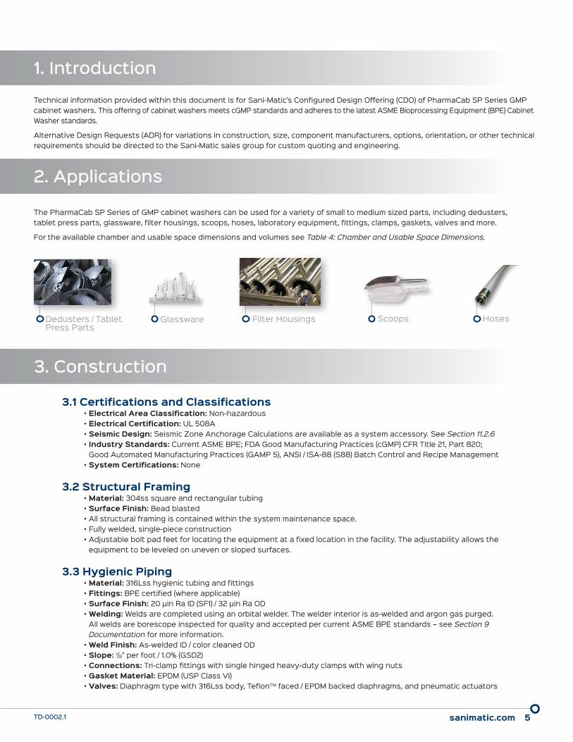
The PharmaCab SP Series of GMP cabinet washers can be used for a variety of small to medium sized parts, including dedusters, tablet press parts, glassware, filter housings, scoops, hoses, laboratory equipment, fittings, clamps, gaskets, valves and more.
For the available chamber and usable space dimensions and volumes see Table 4: Chamber and Usable Space Dimensions.
3.1 Certifications and Classifications• Electrical Area Classification: Non-hazardous• Electrical Certification: UL 508A• Seismic Design: Seismic Zone Anchorage Calculations are available as a system accessory. See Section 11.2.6 • Industry Standards: Current ASME BPE; FDA Good Manufacturing Practices (cGMP) CFR Title 21, Part 820;
Good Automated Manufacturing Practices (GAMP 5), ANSI / ISA-88 (S88) Batch Control and Recipe Management• System Certifications: None
3.2 Structural Framing• Material: 304ss square and rectangular tubing• Surface Finish: Bead blasted• All structural framing is contained within the system maintenance space.• Fully welded, single-piece construction• Adjustable bolt pad feet for locating the equipment at a fixed location in the facility. The adjustability allows the
equipment to be leveled on uneven or sloped surfaces.
3.3 Hygienic Piping• Material: 316Lss hygienic tubing and fittings• Fittings: BPE certified (where applicable)• Surface Finish: 20 µin Ra ID (SF1) / 32 µin Ra OD • Welding: Welds are completed using an orbital welder. The welder interior is as-welded and argon gas purged.
All welds are borescope inspected for quality and accepted per current ASME BPE standards – see Section 9 Documentation for more information.
• Weld Finish: As-welded ID / color cleaned OD • Slope: 1/8" per foot / 1.0% (GSD2) • Connections: Tri-clamp fittings with single hinged heavy-duty clamps with wing nuts • Gasket Material: EPDM (USP Class VI) • Valves: Diaphragm type with 316Lss body, TeflonTM faced / EPDM backed diaphragms, and pneumatic actuators
Scoops HosesGlasswareDedusters / Tablet Press Parts
Filter Housings

sanimatic.com 6TD-0002.1
3.4 Service Panels• Description: Panels located on the load/unload side interface to provide access to interior maintenance space
of the washer• Material: 304ss • Surface Finish: 32 µin Ra• Weld Finish – Load/Unload Side: Ground and polished• Weld Finish – Maintenance Space: Color cleaned• Gasketing: EPDM foam
3.5 Electrical Conduit• Material: Rigid conduit is schedule 40 galvanized pipe with PVC coating. Flexible conduit to be non-metallic UL rated
PVC with nylon fittings. Connection to electrical devices operating at 50 volts and higher is installed with flexible conduit. Connection to low voltage electrical devices is installed with flexible cord. Calibrated instruments are provided with extra cord, allowing them to remain connected when moved to a calibration cart.
3.6 Pneumatics• Location: Instrument air filters, pressure regulators and solenoids are mounted outside the control panel in the
maintenance space.• Material: Pneumatic equipment is connected to the skid mounted solenoid valves with polyethylene tubing.
3.7 Instrument Tags• Description: Each valve, instrument, and equipment is provided with an identification tag containing the
corresponding P&ID tag number• Material: 304ss
4. Utility Requirements
The following are the minimum required utilities for the proper operation of the equipment. If these utilities are not available, an alternate system design may be required.
Table 1: Utility Requirements
Chamber Model
Water - Supply Drain Instrument Air Electrical Chemical
Connection Size / Type
Working Volume (Gal)
Connection Size / Type
Flow Rate (gpm)
Connection Size / Type
Volume (cfm)
Disconnect Size @ 460V
AC (amps)
Connection Size / Type
SP333 1.0" TC 22 1.5" TC ≤ 40 0.5" FNPT 20 100 0.5" TC
SP443 1.0" TC 25 1.5" TC ≤ 40 0.5" FNPT 20 100 0.5" TC
SP444 1.0" TC 25 1.5" TC ≤ 40 0.5" FNPT 20 100 0.5" TC
NOTE:• Drain temperature is variable based on the cycle.
• Water Supply
− Total water volume required is dependent on cycle parameters. − Varying water supply temperatures can be accommodated.
• Two (2) chemical ports located in the chamber sump sidewall are provided for chemical addition. If backflow prevention is required, it is provided by others. See Section 10.10 Chemical Addition for options to add local chemical pump and container assemblies.
• Electrical service is 3PH / 60 Hz

sanimatic.com 7TD-0002.1
5. Physical Size & Layout
The following is the overall size of the equipment as represented in the image below. The default system orientation is a right-handed configuration, with the door swing to the right and the HMI interface to the left when viewing the system from the load side. The Dryer System is a common option selected and is the only option that changes the listed system dimensions.
Table 2: System Size
Chamber Model
System DimensionsMax System Depth -
D Max(in)
Door Swing(in)
System Weight
(lbs)
Dryer - Weight Addition
(lbs)
Dryer - Height Addition
(in)W
(in)D
(in)H
(in)
SP333 96 42 97 53 42 4,300 900 lbs 23
SP443 110 56 97 67 56 4,600 1,000 lbs 23
SP444 110 60 105 71 56 5,400 1,000 lbs 23
NOTE:• System dimensions and system weight listed are for standard options.
• System operating weight is dependent on the construction of the loaded rack.
• The image above shows the addition of the optioned dryer system (see Section 10.4 Dryer System) and a pass-through double door design (see Section 10.1 Door Configuration).
"DOOR SWING"
"DOOR SWING"
"H"
"H DRYER"
"W"
"D MAX" "D"

sanimatic.com 8TD-0002.1
6. Component ManufacturersNote that inclusion of certain components is dependent on the model options selected.
Table 3: Component Manufacturers and Models
Component Manufacturer Model
Chamber Sani-Matic —
Chemical Pump Watson Marlow 313FDM/D
Condensate – Trap Watson McDaniel FTT
Condensate Bypass – Trap Watson McDaniel WT1000
Conductivity Sensors / Transmitters Rosemount 225 / 403 / 1056
Control Enclosure Hoffman CSD
Diaphragm Valves Saunders G or B Series w/ S360 Lite Actuator
Disconnect Switch Siemens LBR Series
Drain Pump Wilden P1
Drain Pump – Isolation Valves VNE EG Series
Drain Pump – Level Switch ifm efector LMT102
Dryer – Butterfly Valves Tru-Flo BFY
Dryer – Fan Cincinnati Fan PBS-10A
Dryer – Heater Tutco Farnum FT600
Dryer – Differential Pressure Transmitter Dwyer 647-3
Dryer – HEPA Filter Flanders 007-W
Dryer – Hoses Ace Sanitary RSD
Dryer Manifold Sani-Matic —
Electric Heater Glo-Quartz D6
Ethernet Switch Phoenix FL
Flow Meter Dynasonics DTFX
Flow Switch ifm efector SI6700
Human Machine Interface Unit(s) Allen-Bradley PanelView Plus 7
PLC Allen-Bradley 1769 CompactLogix
Pressure Gauge Anderson EM
Pressure Transmitter ifm efector PI2304
Level Transmitter – Chamber ifm efector PI2789
Proximity Switches ifm efector IFT / MFS
Rinse Tank Sani-Matic —
Rinse Tank – Filter 3M PFS
Rinse Tank – Filter Housing Fluid Line Technology GA
Rinse Tank – Level Switches Endress & Hauser FTL50H
Rinse Tank – Rupture Disk Fike Axius SC
Sample Valve Top Line SV26
Sanitary Pump / Motor Fristam / WEG FPR3522 / 215TC
Sight Glass / Light LJ Star 3S35 / 36LS
Solenoid Valves SMC SY7000 / SV Series / VX Series
Spray Assemblies Sani-Matic / Spraying Systems —
Steam & Condensate – Ball Valves SVF N8
Steam & Condensate – Check Valves NIBCO T-473-Y
Steam Coil Sani-Matic —
Steam – Pressure Gauge Ashcroft 1009
Steam – Pressure Relief Valve Kunkle 918
Steam – Strainer Titan YS-CS
Steam – Vacuum Breaker Hoffman Specialty Model 62
Sump Strainer Sani-Matic —
Temperature Element / Transmitter Pyromation R5T185L483

sanimatic.com 9TD-0002.1
7. Equipment Description
7.1 ChamberThe chamber contains four (4) rotary spray assemblies mounted to the top, sides, and bottom. The spray assemblies provide repeatable spray coverage to the process parts’ exterior surfaces and the chamber’s interior during all phases of the cycle (pre-rinse, wash, final rinse). Each spray assembly includes orbitally welded spray bases with removable ¼ turn spray nozzles. The spray assemblies are constructed of 316Lss and have Teflon™ rotary unions, which are fluid driven. Each spray assembly includes a magnetic proximity switch to confirm rotation during all phases of the cleaning cycle.
• Chamber construction − Installation Type: Floor Mounted − Thickness: 12 ga. − Insulation: 2" thick chloride free insulation with 304ss sheathing on door(s) only. 0.5" thick closed cell foam insulation on chamber and sump.
− Door(s): Manually operated side-hinged door(s) with a laminated tempered glass viewing window, inflatable EPDM door gasket with low pressure switch to alarm, adjustable position door stop, and proximity switch to confirm door closure.
− Design: Atmospheric − Material: 316Lss wetted surfaces / 304ss non-wetted surfaces − Interior Finish: 20 µin Ra with welds ground and polished − Exterior Finish – Load/Unload Sides: 32 µin Ra with welds ground and polished − Exterior Finish – Maintenance Space: Bead blasted and/or welds color cleaned
• Chamber connections and components − Four (4) Rotary spray assemblies − One (1) Active rack connection – spring loaded TeflonTM coupler mates with parts rack to provide spray coverage to the active rack piping, targeting the interior surfaces of process parts
− Two (2) Rail assemblies for rack guidance with load side wheel stop − One (1) Sump strainer (30 mesh screen) − One (1) Chamber LED light − One (1) Temperature transmitter with 0-100 °C range and 4-20 mA output − One (1) Toroidal conductivity sensor with 0-100 mS/cm range and 4-20 mA output − One (1) Contacting conductivity sensor with 0-10 µS/cm range and 4-20 mA output − One (1) Level transmitter (pressure type) with 0-12" range and 4-20 mA output − Two (2) Water inlet connections (1.0" tri-clamp) − Two (2) Chemical inlet connections (0.5" tri-clamp) − Sanitary tube hangers as required – 316ss with silicone inserts
Chamber and usable dimensions vary by model size, as shown in Table 4: Chamber and Usable Space Dimensions. The usable space dimensions identify the maximum parts loading dimensions, when taking rack design into consideration.
Table 4: Chamber and Usable Space Dimensions
Chamber Model
Chamber Dimensions Usable Space Dimensions Usable Space Volume
(ft3)W" D" H" W" D" H"
SP333 34 34 40 34 29 38 21
SP443 48 48 40 48 43 38 45
SP444 48 52 48 48 47 46 60
Usable Space Dimensions
Chamber Dimensions

sanimatic.com 10TD-0002.1
7.2 Circulation SystemThe circulation system draws solution from the chamber sump and distributes it to the chamber rotary sprays or active rack. It is self-contained within the system’s maintenance space.
• Circulation system components − One (1) 1.5" pneumatic two-way diaphragm valve - system drain − One (1) Centrifugal supply pump
◊ 160 gpm at 46 psi◊ 316Lss wetted materials with EPDM elastomers◊ Silicon carbide vs. silicon carbide internal mechanical seal◊ 3500 rpm, 10 HP, washdown motor◊ 0.5" tri-clamp casing drain connection
− One (1) 0.5" pneumatic two-way diaphragm valve – supply pump casing drain − One (1) Heater outlet temperature transmitter with 0-100 °C range and 4-20 mA output − One (1) Flow switch with discrete output − One (1) Pressure gauge with 0-60 psi range − One (1) 2.0" x 2.0" pneumatic diaphragm horizontal sterile access two-valve assembly for
distributing solution to either the rotary sprays or the rack's active coupler − Hygienic piping manifold
7.3 Heating System• One (1) 6.0" hygienic heater housing assembly• One (1) In-line electric immersion heater
− Material: 316Lss (wetted) − Connections: 6.0" Tri-clamp (process) − Size: 30 kW − Protection: High temperature thermocouple − Duty: See Table 5: Electric Heater Data
7.4 Control System7.4.1 Low Voltage Control Panel
• One (1) UL Listed enclosure, NEMA 4X, 304ss construction with painted carbon steel back plate• One (1) Allen-Bradley 1769 CompactLogix, 1 MB Memory
− Four (4) 8-point discrete input modules − Two (2) 8-point discrete output modules − Two (2) 8-point 4-20 mA analog input modules − One (1) 4-point 4-20 mA analog output module
• One (1) Ethernet hub• Two (2) Low air pressure alarm switches
Table 5: Electric Heater Data
Chamber Model
Electric Heater Sizing
kWApprox. Heatup Time
20 °C to 80 °C(min)
SP333 30 15
SP443 30 20
SP444 30 20
NOTE:• Electric immersion heater may have surface finishes that do not
meet the listed hygienic piping surface finish Ra value.

sanimatic.com 11TD-0002.1
7.4.2 Pneumatics • One (1) Instrument air filter • Two (2) Air pressure regulators with gauges • One (1) Eight-station pneumatic solenoid bank • One (1) Two-station pneumatic solenoid
7.4.3 High Voltage Control Panel• One (1) Fan-cooled UL Listed enclosure, 304ss construction with painted carbon steel back plate• One (1) Circuit breaker rated for 100 Amps • One (1) Disconnect switch rated for 100 amps• One (1) 24V DC, 20 Amp power supply
7.4.4 Load Side Operator InterfaceAll components are mounted through the washer's service panel and are not enclosed (NEMA 1).
• One (1) Allen-Bradley PanelView Plus 7, 7" color touchscreen• One (1) Conductivity analyzer - dual channel• One (1) Illuminated emergency stop switch• One (1) Alarm horn• One (1) Disconnect switch• One (1) Illuminated reset button
8. Equipment Operation
8.1 Loading and Unloading Operation• Loading
− Dirty process parts are loaded onto a parts rack, which sits on a transfer cart − The operator opens the load door − The transfer cart with parts rack is positioned in front of the load door and is pushed into the rail assembly inside the washer for engagement and locking
− The parts rack is pushed from the transfer cart into the chamber and engages with the active coupler − The operator disengages the empty transfer cart from the rail assembly, pulls the transfer cart away from the chamber, and closes the door
− The operator selects the appropriate cleaning cycle from the HMI• Unloading
− The operator opens the unload door at the completion of the cleaning cycle, which is indicated on the HMI − An empty transfer cart is positioned in front of the unload door and is pushed into the rail assembly inside the washer for engagement and locking
− The parts rack is pulled from the chamber onto the transfer cart − The operator disengages the transfer cart from the rail assembly, pulls the transfer cart away from the chamber, and closes the door
− The transfer cart is taken to the appropriate area and clean process parts are unloaded
8.2 Cleaning CycleThe following is an example of a typical cleaning cycle. Drain steps are performed after each rinse or wash phase. The final rinse and subsequent drain steps can be repeated until desired final rinse conductivity levels are met.
• Rinse• Chemical #1 Wash• Rinse• Chemical #2 Wash• Rinse• Final Rinse• Heated Drying (Requires Dryer System option)• Cooling (Requires Dryer System option)
All steps are setup as individual operation codes (Opcodes) enabling full customization of cleaning cycles.

sanimatic.com 12TD-0002.1
8.3 ControlsThe system comes with an Allen-Bradley controls package including a PLC and HMI(s) run on Rockwell FactoryTalk® View Machine Edition (ME) software. The programmable controller provides Ethernet communication protocol. Programming of the PLC and screen development of the HMIs is completed and tested prior to shipment. Cleaning cycle steps are automatically controlled by the programmable controller.
The HMI panel(s) is provided with three (3) levels of security. Each security level has varying levels of system control and screen access.
Up to forty (40) different cleaning cycles can be stored in the PLC. Cycle times are dependent upon many factors such as part type, soil load, available utilities, and drying requirements. The system programming will include adjustable high and low alarms for all measured process values. An operator will have the ability to initiate, monitor and edit (security level dependent) the cleaning cycles via the HMI screens.
8.4 Automation InterfacesThe standard system allows for two (2) 24V DC digital output signals for water fill, as well as two (2) 24V DC digital output signals for chemical addition. The signals are used to activate external equipment (e.g., zero-static block valve) for water fill and chemical addition cycle steps. The cabinet washer system monitors and alarms these incoming utilities as required.
8.5 ReportingThe control system provides data via Ethernet to the owner/user’s process automation system (PAS) for reporting of the cleaning cycle. Tags are available through PLC Ethernet communications.
The following cleaning cycle data is available for reporting:
• Recipe Name• Date• Cycle Start and Stop Time• Cycle Aborted (Yes/No)• Chemical and Final Rinse phase parameters:
− Time − Temperature − Conductivity
• Alarms − Description − Event Time
9. Documentation
One (1) hard copy and one (1) electronic copy of the documentation package is provided as standard. The documentation is provided in the English language and is designed to meet the applicable cGMP and GAMP 5 standards and testing. The following lists the standard documentation – see Section 11.3 Accessory Category - Documentation for additional optioned documents.
• Operation and maintenance manuals• Recommended Spare Parts (RSP) list• Mechanical Bill of Materials (BOM) - serial numbers, model numbers, certifications, ranges and additional information• Instrumentation calibration records - as provided with vendor documentation• Chamber drainability report• Material Test Reports (MTRs)• Weld Maps and Weld Logs including qualification and inspection records• Inspection test results, reports and certificates• Component vendor documentation• As-built General Assembly (GA) drawings• As-built Process and Instrumentation Diagram (P&ID)• As-built electrical drawings

sanimatic.com 13TD-0002.1
10. Product Options
The following are the available product options selectable within the Configured Design Offering for the PharmaCab SP Series.
10.1 Door ConfigurationThe Double Door option adds a second door to the cabinet washer system for a pass-through configuration where load (dirty) side and unload (clean) side operations are physically separated by the cabinet washer system.
In addition to the operator interface described in Section 7.4.3 Load Side Operator Interface, this option adds additional unload side interfaces as well as the necessary controls:
• Unload side operator interface components − One (1) Allen-Bradley PanelView Plus 7, 7" color touchscreen HMI − One (1) Illuminated e-stop − One (1) Alarm horn
• One (1) Pneumatic solenoid valve• One (1) Pressure regulator• One (1) Low pressure switch
The required service panels are installed on the unload side of the system. Controls interlocks are established to prevent both doors being open simultaneously.
10.2 System ConfigurationThe Left Handed option can be chosen for a left handed opening of the door with HMI and operator interfaces on the right side of the system when facing the load side. This layout is a mirror image of what is shown in Section 5 Physical Size & Layout.
10.3 Final Rinse TypeThe Single Pass Final Rinse option adds a final rinse tank and associated controls and piping to the system to allow for a final rinse phase that is not recirculated within the washer chamber.
• Rinse tank: − Working Volume, Dimensions and Access: See Table 6: Rinse Tank Data
− Tank Heads: Flanged and dished − Thickness: 12 ga. − Insulation: 0.5" thick closed cell foam insulation (sidewall only) − Design: Atmospheric − Material: 316Lss wetted surfaces / 304ss non-wetted surfaces − Interior Finish: 20 µin Ra with welds ground and polished − Exterior Finish: 32 µin Ra with welds color cleaned
• Rinse tank components: − One (1) Hygienic spray assembly with directionally drilled static spray ball and supply tube − One (1) Vent filter assembly consisting of an in-line housing with 0.2 micron hydrophobic filter element and two (2) hygienic check valves
− One (1) Rupture disk with +15 psi/full vacuum rating, burst alert sensor, and downtube piping − Two (2) Level switches (tuning fork)
Table 6: Rinse Tank Data
Chamber Model
Rinse Tank
Volume (gal)
Tank Ø(in)
Tank Sidewall(in) Access
SP333 20 12 41 Split tank body (12" tri-clamp)
SP443 40 18 38 6" tri-clamp hand hole
SP444 50 18 46 6" tri-clamp hand hole
sanimatic.com 14TD-0002.1
• Additional circulation system components: − One (1) 2.0" pneumatic two-way diaphragm valve for rinse tank block to pump suction − The standard two-way piping drain valve is replaced with one (1) 2.0" x 1.5" pneumatic diaphragm horizontal sterile access two-valve assembly for distributing chamber solution to either the pump suction (recirculation phase) or to drain (final rinse phase)
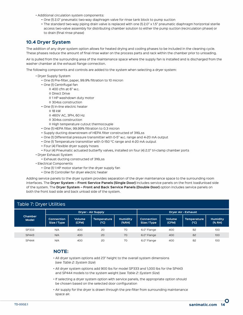
10.4 Dryer SystemThe addition of any dryer system option allows for heated drying and cooling phases to be included in the cleaning cycle. These phases reduce the amount of final rinse water on the process parts and rack within the chamber prior to unloading.
Air is pulled from the surrounding area of the maintenance space where the supply fan is installed and is discharged from the washer chamber at the exhaust flange connection.
The following components and controls are added to the system when selecting a dryer system:
• Dryer Supply System − One (1) Pre-filter, paper, 99.9% filtration to 10 micron − One (1) Centrifugal fan
◊ 400 cfm at 6" w.c.◊ Direct Drive◊ 1 HP washdown duty motor◊ 304ss construction
− One (1) In-line electric heater◊ 18 kW◊ 460V AC, 3PH, 60 Hz◊ 304ss construction◊ High temperature cutout thermocouple
− One (1) HEPA filter, 99.99% filtration to 0.3 micron − Supply ducting downstream of HEPA filter constructed of 316Lss − One (1) Differential pressure transmitter with 0-5" w.c. range and 4-20 mA output − One (1) Temperature transmitter with 0-150 °C range and 4-20 mA output − Four (4) Flexible dryer supply hoses − Four (4) Pneumatic actuated butterfly valves, installed on four (4) 2.0" tri-clamp chamber ports
• Dryer Exhaust System − Exhaust ducting constructed of 316Lss
• Electrical Components − One (1) 1 HP motor starter for the dryer supply fan − One (1) Controller for dryer electric heater
Adding service panels to the dryer system provides separation of the dryer maintenance space to the surrounding room interfaces. The Dryer System – Front Service Panels (Single Door) includes service panels on the front load/unload side of the system. The Dryer System – Front and Back Service Panels (Double Door) option includes service panels on both the front load side and back unload side of the system.
Table 7: Dryer Utilities
Chamber Model
Dryer - Air Supply Dryer Air - Exhaust
Connection Size / Type
Volume (CFM)
Temperature (°C)
Humidity (%RH)
Connection Size / Type
Volume (CFM)
Temperature (°C)
Humidity (% RH)
SP333 N/A 400 20 70 6.0" Flange 400 82 100
SP443 N/A 400 20 70 6.0" Flange 400 82 100
SP444 N/A 400 20 70 6.0" Flange 400 82 100
NOTE:• All dryer system options add 23" height to the overall system dimensions
(see Table 2: System Size)
• All dryer system options add 900 lbs for model SP333 and 1,000 lbs for the SP443 and SP444 models to the system weight (see Table 2: System Size)
• If selecting a dryer system option with service panels, the appropriate option should be chosen based on the selected door configuration
• Air supply for the dryer is drawn through the pre-filter from surrounding maintenance space air.

sanimatic.com 15TD-0002.1
10.5 Recirculated HeatingThe Steam option removes the electric heater from the base system and replaces it with a steam coil system for heating of the circulation system. The following components are added:
• One (1) Steam coil with the following specifications: − Duty: See Table 8: Steam Heating Data − Material: 316Lss − Insulation: None − Design: In-line coil − Rating: Non-ASME − Connections: 6.0" Tri-clamp (process), 0.5" tube - compression fittings (utility)
• One (1) 6.0" Hygienic steam coil housing assembly• One (1) Steam supply piping manifold constructed of SCH80 carbon steel socket weld pipe and fittings
− One (1) Y-Strainer with blow-off valve − One (1) Pressure gauge with manual ball valve for isolation − One (1) Modulating control v-ball valve with pneumatic actuator and positioner − One (1) Steam pressure relief valve (set at 125 psi) piped to the floor − One (1) Vacuum breaker with brass construction
• One (1) Condensate return manifold constructed of SCH80 carbon steel socket weld pipe and fittings − One (1) Manual ball valve for condensate drain − One (1) Float and thermostatic steam trap − One (1) Check valve for condensate return isolation
• One (1) Condensate bypass manifold constructed of SCH80 carbon steel socket weld pipe and fittings − One (1) Balanced pressure thermostatic steam trap − One (1) Check valve for condensate return isolation
10.6 Supply Pressure MonitoringThe Pressure Transmitter option replaces the pressure gauge in the circulation system with a diaphragm type pressure transmitter. The pressure transmitter has 0-60 psi range and 4-20 mA output. This option adds system monitoring and alarming capabilities for the supply pressure.
Table 8: Steam Heating Data
Chamber Model
Approx. Heatup Time 20 °C to 80 °C
(min)
Connection Size / Type(Steam Supply)
Connection Size / Type (Condensate Return)
Load (lbs / hr)
SP333 10 0.75" Flange 0.5" Flange 120
SP443 10 0.75" Flange 0.5" Flange 180
SP444 10 0.75" Flange 0.5" Flange 180
NOTE:• The standard design is sized for applications with 50 psi steam. Installations where
the plant supplied steam is in excess of 50 psi may require a pressure reducing valve (PRV). Unless otherwise specified, it is assumed that the PRV is customer supplied and/or installed by others.
sanimatic.com 16TD-0002.1
10.7 Supply Flow MonitoringThe Flow Meter option replaces the flow switch in the circulation system with an ultrasonic style flow meter, mounted external to the hygienic tubing. The flow meter has 0-200 gpm range and 4-20 mA output. This option adds system monitoring and alarming capabilities for the supply flow.
10.8 ReportingThe Report Ticket Printer option adds a thermal serial printer to the system. The printer enables the system to provide a printed report containing the wash parameters detailed in Section 8.5 Reporting. All report data is stored in a buffer that is flushed upon starting the next cleaning cycle. The printer is mounted through the washer’s unload side service panel. Additional controls include a 120V power transformer in the HV electrical enclosure and a 120V power receptacle mounted behind the service panel.
10.9 Water AdditionThe water addition options (Dual Water Ports with (1) Pneumatic Valve and Dual Water Ports with (2) Pneumatic Valves) add one (1) or two (2) 1.0" tri-clamp standard two-way diaphragm valves to the chamber water inlet ports for automatic water feed control.
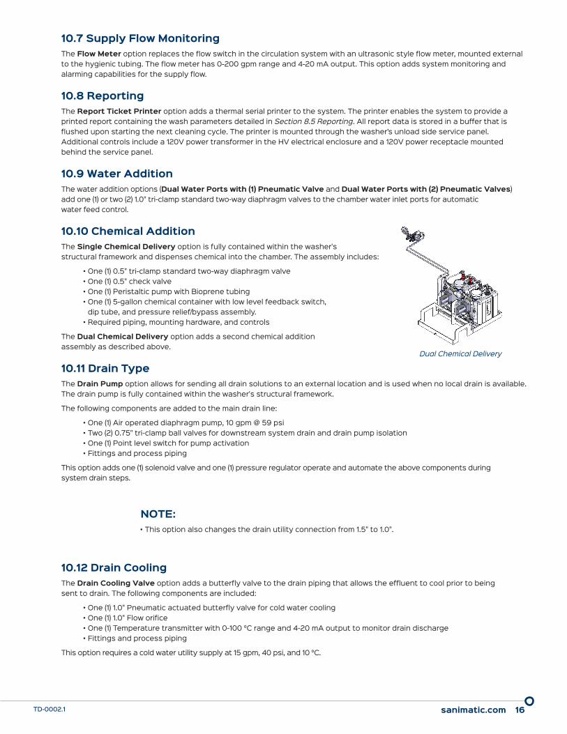
10.10 Chemical AdditionThe Single Chemical Delivery option is fully contained within the washer's structural framework and dispenses chemical into the chamber. The assembly includes:
• One (1) 0.5" tri-clamp standard two-way diaphragm valve• One (1) 0.5" check valve• One (1) Peristaltic pump with Bioprene tubing• One (1) 5-gallon chemical container with low level feedback switch,
dip tube, and pressure relief/bypass assembly.• Required piping, mounting hardware, and controls
The Dual Chemical Delivery option adds a second chemical addition assembly as described above.
10.11 Drain TypeThe Drain Pump option allows for sending all drain solutions to an external location and is used when no local drain is available. The drain pump is fully contained within the washer's structural framework.
The following components are added to the main drain line:
• One (1) Air operated diaphragm pump, 10 gpm @ 59 psi• Two (2) 0.75" tri-clamp ball valves for downstream system drain and drain pump isolation• One (1) Point level switch for pump activation• Fittings and process piping
This option adds one (1) solenoid valve and one (1) pressure regulator operate and automate the above components during system drain steps.
10.12 Drain CoolingThe Drain Cooling Valve option adds a butterfly valve to the drain piping that allows the effluent to cool prior to being sent to drain. The following components are included:
• One (1) 1.0" Pneumatic actuated butterfly valve for cold water cooling• One (1) 1.0" Flow orifice• One (1) Temperature transmitter with 0-100 °C range and 4-20 mA output to monitor drain discharge• Fittings and process piping
This option requires a cold water utility supply at 15 gpm, 40 psi, and 10 °C.
Dual Chemical Delivery
NOTE:• This option also changes the drain utility connection from 1.5" to 1.0".
sanimatic.com 17TD-0002.1
11. Accessories
The following are the available accessories selectable to accompany the PharmaCab SP Series Configured Design Offering. The accessories are separated into four categories – accessories related to Racks, System Additions, Documentation, and Field Service.
11.1 Accessory Category – RacksThe Racks category of accessories contains information regarding Sani-Matic custom-designed racks. Three levels of budgetary rack categories are highlighted below in Sections 11.1.1–11.1.3. Transfer carts required to load and unload the racks from the washer and move parts through the installed facility are detailed in Sections 11.1.7–11.1.9.
The rack design process typically begins with a preliminary parts load list, which is defined by mutual Sani-Matic and owner/user efforts. Two different 3D modeling service options are provided for developing 3D models of the load lists’ process parts. After the process parts are 3D modeled, a preliminary rack configuration is developed and sent for review and approval. Finalized rack design is completed and detailed General Assembly (GA) drawings are sent for review and approval. The cost difference between budgetary and final design is adjusted during the project.
All racks are designed to fit the chamber dimensions shown in Table 4: Chamber and Usable Space Dimensions. Rack designs incorporate an active coupler that ties into the cabinet washer’s circulation manifold, which supplies the necessary flow and pressure through the active rack’s manifold to the active sprays and/or active part connections (e.g., valves, hoses, small fittings). Support framework is manufactured of 316Lss and has a 20 µin Ra finish with welds ground and polished to match the interior of the chamber. Delicate parts such as glassware can be held by thermoplastic supports to eliminate or minimize part contact with stainless. Other frame surface finishes and/or weld finishes can be accommodated if required. The racks are manually rolled between the transfer carts and the cabinet chamber on four (4) Teflon™ roller wheels.
NOTE:• All racks listed below are priced as budgetary and are to be used as budget
placeholders until the rack design is finalized and approved.
• The quantities for parts, active sprays, and active part connections below are general guidelines only for budgetary estimating.
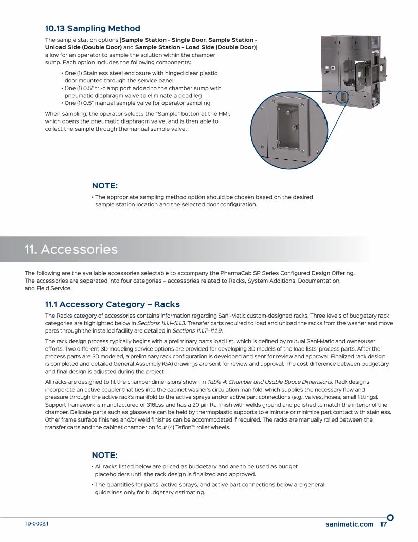
10.13 Sampling MethodThe sample station options [Sample Station - Single Door, Sample Station - Unload Side (Double Door) and Sample Station - Load Side (Double Door)] allow for an operator to sample the solution within the chamber sump. Each option includes the following components:
• One (1) Stainless steel enclosure with hinged clear plastic door mounted through the service panel
• One (1) 0.5" tri-clamp port added to the chamber sump with pneumatic diaphragm valve to eliminate a dead leg
• One (1) 0.5" manual sample valve for operator sampling
When sampling, the operator selects the “Sample” button at the HMI, which opens the pneumatic diaphragm valve, and is then able to collect the sample through the manual sample valve.
NOTE:• The appropriate sampling method option should be chosen based on the desired
sample station location and the selected door configuration.
sanimatic.com 18TD-0002.1
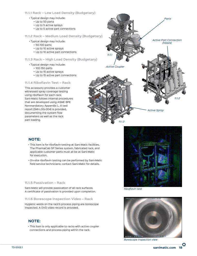
11.1.1 Rack – Low Load Density (Budgetary)• Typical design may include:
− Up to 50 parts − Up to 5 active sprays − Up to 5 active part connections
11.1.2 Rack – Medium Load Density (Budgetary)• Typical design may include:
− 50-100 parts − Up to 10 active sprays − Up to 10 active part connections
11.1.3 Rack – High Load Density (Budgetary)• Typical design may include:
− 100-150 parts − Up to 15 active sprays − Up to 15 active part connections
11.1.4 Riboflavin Test – RackThis accessory provides a customer witnessed spray coverage testing using riboflavin for each rack. Sani-Matic follows internal procedures that are developed using ASME BPE Nonmandatory Appendix L. A test report (SMI-LOG-004) is provided, documenting the system flow parameters as well as the rack part loading.
11.1.5 Passivation – RackSani-Matic will provide passivation of all rack surfaces. A certificate of passivation is provided upon completion.
11.1.6 Borescope Inspection Video – RackHygienic welds on the rack’s process piping are borescope inspected. A DVD video record is provided.
NOTE:• This item is for riboflavin testing at Sani-Matic facilities.
The PharmaCab SP Series system, fabricated rack, and applicable customer parts must all be at Sani-Matic for execution.
• On-site riboflavin testing can be performed by Sani-Matic field service technicians; contact Sani-Matic for details.
NOTE:• This item is only applicable to racks with active coupler
connections and process piping within the rack.
Riboflavin test
Borescope inspection view
11.1.1
Parts
Active Part Connection(Hoses)
Active Coupler
Active Spray
11.1.2
11.1.3

sanimatic.com 19TD-0002.1
11.1.7 Transfer Cart – SP333Transfer carts are used to move the racks throughout the facility. Transfer carts are designed to hold one rack. A tray with a detachable collection bottle is provided to catch process soils and/or liquid during the transport through the facility. The transfer carts are manufactured of 304ss and have a 32 µin Ra finish with welds color cleaned. Carts are supported by two (2) straight and two (2) locking swivel casters of nylacron material.
The footprint of the SP333 transfer cart is 37" W x 51" D and the loading rail height is 36".
11.1.8 Transfer Cart – SP443Transfer carts are used to move the racks throughout the facility. Transfer carts are designed to hold one rack. A tray with a detachable collection bottle is provided to catch process soils and/or liquid during the transport through the facility. The transfer carts are manufactured of 304ss and have a 32 µin Ra finish with welds color cleaned. Carts are supported by two (2) straight and two (2) locking swivel casters of nylacron material.
The footprint of the SP443 transfer cart is 51" W x 65" D and the loading rail height is 36".
11.1.9 Transfer Cart – SP444Transfer carts are used to move the racks throughout the facility. Transfer carts are designed to hold one rack. A tray with a detachable collection bottle is provided to catch process soils and/or liquid during the transport through the facility. The transfer carts are manufactured of 304ss and have a 32 µin Ra finish with welds color cleaned. Carts are supported by two (2) straight and two (2) locking swivel casters of nylacron material.
The footprint of the SP444 transfer cart is 51" W x 69" D and the loading rail height is 36".
11.1.10 Part 3D Modeling – Design Cost (per Part)This service is for generating a 3D model of each unique customer process part to be cleaned on a rack. The modeling will allow specific design elements to be incorporated into the rack and allow for repeatable part placement on the rack. Identical process parts will only require one (1) modeling fee.
11.1.11 Part 3D Modeling – Trip (Budgetary)This service sends a Sani-Matic design engineer to the customer location to perform the 3D modeling described in Section 11.1.10 Part 3D Modeling – Design Cost (per Part). This option is a budgetary value based on the provision of one (1) Sani-Matic design engineer for two (2) days, sixteen (16) hours of travel, and four (4) days of expenses.
NOTE:• Parts need to be shipped to Sani-Matic’s facility for this option.
NOTE:• If selecting this accessory, the per part cost described in Section
11.1.10 Part 3D Modeling – Design Cost (per Part) does not apply.
• The final invoice is based on the actual hours worked and expenses invoiced at cost.

sanimatic.com 20TD-0002.1
11.2 Accessory Category – System AdditionsThe Accessory Category – System Additions contains optioned items that can be added onto any PharmaCab SP Series Configured Design Offering system configuration.
11.2.1 Passivation – SystemSani-Matic will provide factory passivation of all solution contact surfaces on the system. The citric acid passivation is performed and documented per Sani-Matic’s standard procedure (SOP-MA005), which adheres to ASTM A 967-05 requirements. A certificate of passivation (SMI-LOG-007) is provided upon completion.
11.2.2 Hydrostatic TestUnder this System Addition option, Sani-Matic will provide a hydrostatic test of the system’s piping. The hydrostatic test is performed per Sani-Matic’s standard procedure (SOP-QA007) based on ASME guidelines. A certificate of hydrostatic testing (SMI-LOG-002) is provided upon completion.
11.2.3 Riboflavin Test – ChamberThis is a customer-witnessed riboflavin spray coverage test for areas of the chamber which have the potential to drip onto a rack. Sani-Matic follows internal SOPs that are developed using ASME BPE Nonmandatory Appendix L as a guideline. A test report (SMI-LOG-004) is provided, documenting the system test parameters.
11.2.4 Riboflavin Test – Rinse TankThis is a customer-witnessed riboflavin spray coverage test for the final rinse tank. Sani-Matic follows internal SOPs that are developed using ASME BPE Nonmandatory Appendix L as a guideline. A test report (SMI-LOG-004) is provided, documenting the system test parameters.
11.2.5 Borescope Inspection Video - SystemThe system's process piping hygienic welds are borescope inspected and a DVD video record is provided.
11.2.6 Seismic Zone Anchorage CalculationsSeismic calculations are performed for the anchorage of the system to the plant floor. The services are performed by an engineer certified in the state where the system will be installed in and includes documentation on the calculations and a licensed engineer's stamp.
11.2.7 Barrier FlangesEight pieces of L-shaped 16 ga., 32 µin Ra, 304ss barrier flanges (profile dimensions: 1.5" x 2.5" x 11' L) are shipped loose for both the load side and unload side to allow the exterior of the washer to be sealed to the walls, floor, and ceiling to reduce airflow between areas of different pressurization. The barrier flange design requires adhesive to attach the flanges to the cabinet washer frame and paneling.
NOTE:• Due to the unique seismic zone considerations for each installation,
modifications to the system design and footprint may be required, which may incur additional charges.
NOTE:• This accessory can only be selected if the Single Pass Final Rinse
system option is selected.

sanimatic.com 21TD-0002.1
11.3 Accessory Category – DocumentationThe Accessory Category – Documentation contains optional documents for the PharmaCab SP Series system that support validation efforts.
11.3.1 Functional Specification (FS)The Functional Specification (FS) is a detailed operational specification document and is provided in Sani-Matic’s standard format.
11.3.2 Configuration Specification (CS)The Configuration Specification (CS) is a detailed specification on the control components and software and is provided in Sani-Matic’s standard format.
11.3.3 Factory Acceptance Test (FAT)The Factory Acceptance Test (FAT) includes both the FAT protocol document as well as the onsite FAT execution. The document is provided in Sani-Matic’s standard format. The FAT execution is performed and documented prior to shipment and includes up to four (4) days of onsite owner/user participation. Sani-Matic’s testing facilities include 460V AC, 3PH, 60Hz electrical power, compressed air, plant steam (as required), and low conductivity DI water allowing the system to be tested under design conditions. Testing will include a step-by-step written verification test of all electrical and hardware functions. Additional onsite owner/user time can be purchased if needed.
11.3.4 Site Acceptance Test (SAT) DocumentThe Site Acceptance Test (SAT) document provides a detailed commissioning protocol to assist with the owner/user’s site acceptance testing, including step-by-step written verification testing of all electrical and mechanical hardware functions, and is provided in Sani-Matic’s standard format.
11.3.5 Installation Qualification / Operational Qualification (IQ/OQ)The Installation Qualification (IQ) and Operational Qualification (OQ) documents together provide a documented method for verification to ensure the system has been properly installed and that it is operating as designed. The document is provided in Sani-Matic’s standard format.
11.3.6 Instrument Data SheetsInstrument Data Sheets are provided for the instruments included with the system. The data sheets are provided in Sani-Matic’s standard format which is based on the ISA (International Society of Automation) format.
11.3.7 Traceability MatrixThe Traceability Matrix document provides traceability of the system specifications in the FS, CS, FAT, SAT, and IQ/OQ documents back to an owner/user provided user requirements specification (URS). The traceability matrix is in Sani-Matic’s standard format and is provided after system shipment.
NOTE:• The Traceability Matrix will only contain traceability from the
owner/user URS to the validation documents included in the system purchase.

sanimatic.com 22TD-0002.1
11.4.1 Installation Assistance (Budgetary)An on-site Sani-Matic technician assists in installation of the equipment, including ensuring that equipment is verified to be reassembled properly, leveled, and correct utilities connected as required.
This add-on is priced with the assumption of one (1) technician providing twenty (20) hours of weekday on-site time over two (2) days, sixteen (16) hours of weekday travel over two (2) days, and all travel, lodging, and meal expenses. Additional hours and expenses utilized for any onsite activities will be billed accordingly.
11.4.2 Start-up & Training (Budgetary)A Sani-Matic technician will be on-site and can assist in startup and training activities. The technician will assist with general startup procedures, and training activities can include operational and HMI training of operators, engineers, and/or maintenance technicians.
This add-on is priced with the assumption of one (1) technician providing forty (40) hours of weekday onsite time over four (4) days, sixteen (16) hours of weekday travel over two (2) days, and all travel, lodging, and meal expenses. Additional hours and expenses utilized for any on-site activities will be billed accordingly.
11.4.3 SAT Assistance (Budgetary)A Sani-Matic technician will be on-site and can assist with the execution of the SAT of the system and controls at the customer’s facility.
This add-on is priced with the assumption of one (1) technician providing thirty (30) hours of weekday onsite time over three (3) days, sixteen (16) hours of weekday travel over two days, and all travel, lodging, and meal expenses. Additional hours and expenses utilized for any on-site activities will be billed accordingly.
11.4.4 IQ/OQ Assistance (Budgetary)A Sani-Matic technician will be on-site and can assist with the execution of the IQ/OQ protocols at the customer’s facility.
This add-on is priced with the assumption of one (1) technician providing thirty (30) hours of weekday on-site time over three (3) days, sixteen (16) hours of weekday travel over two (2) days, and all travel, lodging, and meal expenses. Additional hours and expenses utilized for any on-site activities will be billed accordingly.
11.4.5 On-site Rack Assistance (Budgetary)A Sani-Matic technician will be on-site and can assist with activities related to rack validation such as performing or assisting in riboflavin testing, rack modifications, or assessing rack designs to add additional parts.
This add-on is priced with the assumption of one (1) technician providing thirty (30) hours of weekday on-site time over three (3) days, sixteen (16) hours of weekday travel over two (2) days, and all travel, lodging, and meal expenses. Additional hours and expenses utilized for any on-site activities will be billed accordingly.
NOTE:• For the field service assistance accessories see Sections 11.4.1
through 11.4.5, the final invoice is based on the actual hours and expenses with the expenses invoiced at Sani-Matic costs.
11.4 Accessory Category – Field ServiceThe Accessory Category – Field Service contains after-sale services to support smooth and successful installation and validation activities and keep your system maintained for years of reliable service.
All pricing quoted are budgetary estimates based on the hours and expenses of the activity. The invoice price is based on the ac-tual hours and expenses with a minimum eight (8) hours per day per technician (sum of both onsite and travel time) and with the expenses invoiced at Sani-Matic costs. To minimize the time spent onsite and fully utilize the technician’s time, it is recommended that the equipment be fully installed and ready for operation prior to scheduling the technician’s trip. A checklist is provided to assist in ensuring that the equipment is ready.

sanimatic.com 23TD-0002.1
11.4.6 Preventative Maintenance (PM) Program (Budgetary)The goal of Sani-Matic’s preventative maintenance program is to make sure that the equipment and operators are running efficiently and to reduce time lost due to unexpected equipment failures. The two (2) field service trips included as part of this program are:
• 6-month checkup − Check instrument calibration − Review PLC / HMI applications − Training
• 1-year PM execution (customer procured parts) − Check instrument calibration − Change out elastomers − Change pump seals − Change out wearables / consumables − Review PLC / HMI applications − Training
Contact Sani-Matic for other offering levels of PM services.
11.4.7 Recommended Spare Parts (RSP) Budget (Budgetary)Sani-Matic will provide a loose ship package of critical Recommended Spare Parts (RSP) for the PharmaCab SP Series system (e.g., pump seals, elastomers, diaphragms). The RSP list for loose ship parts is sent for review and approval, after which the final pricing will be provided.