Embed Size (px)
Citation preview
DOC 98-70-18(Volume 3 of 10)
PHARE Advanced ToolsConflict Probe
Final ReportPHARE/NLR/PAT-6.4.4/FR; 1.0
EUROCONTROL96 rue de la Fusée
B-1130 BRUXELLES
Prepared by: H.J. Kremer,
W.C. Vertegaal,
R.B.H.J. Jansen, NLR
Date: July 1999

Copyright Statement PATS Conflict Probe, Final Report
-2- Version 1.0 / July 1999 DOC 98-70-18/3
The information contained in this report is the property of the PHARE Participants*.
The report or parts thereof may be published and or reproduced on the conditionthat due acknowledgement of authorship is made by quoting the copyrightstatement below. The copyright and the foregoing condition on publication andreproduction shall extend to all media in which the information may be embodied.
The information contained in this document is provided on an "as-is" basis and thePHARE Participants shall provide no express or implied warranty of any kind andshall accept no liability whatsoever for or in connection with the use of theinformation contained in the document.
* The PHARE Participants are:
- the EUROCONTROL Agency;
- the CENA (Centre d'études de la navigation aérienne);
- the STNA (Service technique de la navigation aérienne);
- the NLR (Nationaal Lucht- en Ruimtevaartlaboratorium);
- the RLD (Rijksluchtvaartdienst);
- the LVNL (Luchtverkeersleiding Nederland);
- the DLR (Deutsches Zentrum für Luft- und Raumfahrt);
- the DFS (Deutsche Flugsicherung GmbH);
- the UK CAA (Civil Aviation Authority);
- the NATS (National Air Traffic Services);
- the DERA (Defence Evaluation and Research Agency)
Copyright statement:
The copyright in this report vests in the European Organisation for the Safety of AirNavigation (EUROCONTROL); the CENA (Centre d'études de la navigationaérienne); the STNA (Service technique de la navigation aérienne); the NLR(Nationaal Lucht- en Ruimtevaartlaboratorium); the RLD (Rijksluchtvaartdienst); theLVNL (Luchtverkeersleiding Nederland); the DLR (Deutsches Zentrum für Luft- undRaumfahrt); the DFS (Deutsche Flugsicherung GmbH); the UK CAA (Civil AviationAuthority); the NATS (National Air Traffic Services) and the DERA (DefenceEvaluation and Research Agency).
All rights reserved.

PATS Conflict Probe, Final Report Revision History
DOC 98-70-18/3 Version 1.0 / July 1999 -3-
REVISION HISTORY
Date Revision Number Reason for revision
1998-06-12 0.1 Skeleton draft
1998-08-10 0.2 Revised skeleton and completed
1998-12-11 0.3 Revised and completed
1999-07-22 1.0 Publication Version

Copyright Statement PATS Conflict Probe, Final Report
-4- Version 1.0 / July 1999 DOC 98-70-18/3
DOCUMENT APPROVAL
NAME SIGNATURE DATE
AUTHOR 1 H.J. Kremer 30 Jul 99
AUTHOR 2 W.C. Vertegaal 30 Jul 99
AUTHOR 3 R.B.H.J. Jansen 30 Jul 99
Project Leader I. Wilson 30 Jul 99
PHARE ProgrammeManager
H. Schröter 30 Jul 99
PATS Conflict Probe, Final Report Executive Summary
DOC 98-70-18/3 Version 1.0 / July 1999 -5-
EXECUTIVE SUMMARY
This document is part of the final report for the PHARE Advanced Tools (PATs).Within the PATs project decision support tools for controllers are developed withresearch purposes. One tool out of the PATs set is the Conflict Probe (CP). The CPprovides an advanced conflict probing function. This document focuses on thedevelopment of the PATs CP1.
The CP probes system plans to detect any conflict that may occur between aircraft,based on their system plans (SPLs) (in this document referred to as SPL conflictprobing). A conflict is defined as a possible infringement of certain safety rules. Forthis, the CP compares Active System Plans with each other. Active System Plansrepresent the flight paths according to which aircraft are currently flying.Furthermore, the CP probes Alternative System Plans for conflicts. AlternativeSystem Plans represent flight paths that are suggested by other parts of the AirTraffic Management (ATM) system (“what if” situations). The CP comparesAlternative System Plans with each other and compares Alternative System Planswith all Active System Plans.
As a second functionality, the CP probes system plans to detect any areainfringement that may occur between aircraft and a restricted area where theaircraft is not allowed to go (in this document referred to as area conflict probing). Inthis respect, an area infringement is defined as a situation in which aircraft fly withinthe restricted area. Area infringements are also referred to as area conflicts.Examples of such restricted areas are Temporarily Restricted Areas (TRAs) andSignificant Meteorological areas (SIGMETs). To detect area infringements, bothActive and Alternative System Plans are compared with restricted areas.
Two different concepts have been used to execute SPL conflict probing (protectionzone SPL conflict probing (PD/1) and nominal path SPL conflict probing (PD/2,PD/3). Furthermore, probabilistic SPL conflict probing and area conflict probingalgorithms were developed at NLR. However, area conflict probing was notexercised in the PHARE demonstrations. Probabilistic conflict information could notbe handled functionally within the simulation systems which were geared to conflictswith geometric certainty and therefore this information has not been used.
The CP is used both by Air Traffic Controllers (ATCos) and other PATs. Theinteraction between the CP and the ATCo takes place through the Human MachineInterface (HMI). This HMI was developed by the Ground Human Machine Interface(GHMI) project. The interface between the CP and the other PATs was developedwithin the PATs project.
The development of the Conflict Probe was by means of a stepwise progressionthrough a series of PHARE Demonstrations (PDs). PD/1 took place in late 1995,PD/2 took place in June 1996 and PD/3 took place in 1998.
PD/1, hosted by NATS, was based on an en-route scenario. An initial version of theCP was developed and integrated with other tools within a framework called theCommon Modular Simulator (CMS). The scope of this version of the CP was todetect conflicts in the en-route sector. This version of the CP was based onprotection zone SPL conflict probing. The existing NLR Area Conflict Detection(ACOD) algorithms were the basis for this version of the CP.
1 In this document, the terms PATs CP and CP are both used for the same developed conflict probing tool.
Executive Summary PATS Conflict Probe, Final Report
-6- Version 1.0 / July 1999 DOC 98-70-18/3
PD/2, hosted by DLR, was based on a Terminal Manoeuvring Area (TMA) scenario.A nominal path SPL conflict probing algorithm that could handle the more dynamicnature of air traffic in the TMA replaced the algorithm of the PD/1 version of the CP.Also TMA characteristic SPL conflict probing difficulties such as wake vortexconflicts and conflicts on the ground were handled by the PD/2 version of the CP.
PD/3, hosted by NLR, EEC, and CENA, was based on a multi-sector scenario. Thisscenario included the full route of aircraft from take off to touch down. Area conflictprobing algorithms were developed for the PD/3 version of the CP.
In all PHARE Demonstrations and Internal Operational Clarification Projects(IOCP), the CP activities could only be seen through GHMI. Underneath the GHMI,the CP delivered a lot of information to other tools that benefited from thatinformation. There were no problems reported concerning the use of the CP byother PATs. The results that are available from the various demonstrations arebased on the CP information that was seen through GHMI. Most comments that arecollected from the controllers concern the way the CP information is shown throughGHMI.
In all PHARE Demonstrations, PD/1 to PD/3, the CP has had an important functionwithout which the system would not have been complete. The latest version of theCP has been integrated on three platforms: NARSIM at NLR, ESCAPE at EEC andDAARWIN at CENA. Also a stand-alone version of the CP has been developedsuch that stand-alone tests can be done.
The development of the CP aimed for the following main goals:
1. Develop a tool box function in composition with other PATs,
2. Develop a research tool in the area of conflict probing,
3. Develop a tool that can be easily adapted to meet new (research) requirements,
4. Develop a tool that can be easily integrated in several ATC environments.
The first goal, to develop a tool box function in composition with other PATs, hasnot fully been reached to our satisfaction. Some interactions with other PATs arenot satisfying, because the possibility of conflict inconsistencies still exist in thePATs cluster (CP conflicts as opposed to Cooperative Tools (CT) conflicts andHighly Interactive Problem Solver (HIPS) conflicts). The second goal to develop aresearch tool in the area of conflict probing has fully been reached. Furthermore,the CP software can easily be adapted to any environment and new algorithms caneasily replace existing algorithms. So also the last two goals have been reached.
With respect to the development path of the CP, the following can be concluded.The purpose of the PATs project was that the tools would be developed in asimulation environment called CMS. When all tools would have been integrated onthe same simulation platform, test runs could have been made and the PATs clustercould have been evaluated and validated. However, the development of thesimulation environment CMS was planned parallel to the development of the tools.The result of this parallel approach was that a lot of time was needed for the tooldevelopers to integrate the tools in successive CMS versions. Lesson learnt is thatthe development of the simulation environment, in which ATC tools can beevaluated and validated, should be done before the development of the toolsthemselves start.
It turned out that the approach followed by the PATs project is a tool drivenapproach rather than a concept driven approach. With a tool driven approach, thesometimes almost independent development of tools is meant. Only after sometools' developments were finished, it turned out that some tools had incorporated
PATS Conflict Probe, Final Report Executive Summary
DOC 98-70-18/3 Version 1.0 / July 1999 -7-
conflicting or overlapping functionalities. In general, the tools were not optimalconsistent with each other.
For a successful development of an ATC tools cluster, a concept driven approachwould have been better. This means that tools should be developed according tocommon concepts, which everybody agrees upon, and the various activities mustbe geared to one another in a greater extent than was done within this project.
The PHARE project has generated a lot of information that can be used as input toother projects in the field of ATC. From the CP development the following ideas arerecommended as a basis for further research.
To reduce the possibility of having inconsistencies in conflict reports from variousPATs, the CP development team had decided to perform SPL conflict probing usingthe nominal path SPL conflict probing approach. This approach is easy tounderstand and interpret such that other PATs that perform SPL conflict probingcan tune their SPL conflict probing approach to minimise inconsistencies in thePATs cluster.
The latest development in the SPL conflict probing area, the probabilistic approach,was not used to detect conflicts during the PHARE demonstrations. However,research in the area of probabilistic SPL conflict probing is recommended, becauseit can provide information upon which the decision making processes of thecontrollers can be improved. An important question in this area is how theinformation that can be generated by the probabilistic SPL conflict probing approachshould be presented to the controllers. This question is recommended as a subjectfor further research as well. This research should be done in co-operation withhuman factor experts.

PATS Conflict Probe, Final Report
-8- Version 1.0 / July 1999 DOC 98-70-18/3
This page left intentionally blank

PATS Conflict Probe, Final Report List of Contents
DOC 98-70-18/3 Version 1.0 / July 1999 -9-
LIST OF CONTENTS
1. INTRODUCTION................................................................................................... 11
1.1. SCOPE ................................................................................................................ 11
1.2. DOCUMENT CONTEXT........................................................................................... 11
1.3. OVERVIEW........................................................................................................... 11
1.4. DOCUMENT STRUCTURE ....................................................................................... 12
2. OPERATIONAL CONCEPTS ............................................................................... 13
2.1. OPERATIONAL CONCEPT ...................................................................................... 13
2.1.1. Overview of operation............................................................................... 13
2.1.2. Key operational concepts ......................................................................... 14
2.2. CONTEXT DESCRIPTION ....................................................................................... 19
2.2.1. Sub-system Terminators........................................................................... 20
2.2.2. Sub-system Inputs.................................................................................... 21
2.2.3. Sub-system outputs.................................................................................. 22
2.3. DEVELOPMENT PROCESS ..................................................................................... 22
2.3.1. History of Tool Development .................................................................... 22
2.3.2. Why it was developed that way ................................................................ 22
2.3.3. Dropped ideas and concepts .................................................................... 23
3. REQUIREMENT DESCRIPTION........................................................................... 25
3.1. USER REQUIREMENTS .......................................................................................... 25
3.2. FUNCTIONAL REQUIREMENTS................................................................................ 25
3.3. IMPLEMENTATION DEPENDENT REQUIREMENTS ...................................................... 25
3.3.1. Integration ................................................................................................ 25
3.3.2. Client/server architecture.......................................................................... 26
3.3.3. Platform independent ............................................................................... 26
3.3.4. Configuration data source......................................................................... 26
4. IMPLEMENTATION .............................................................................................. 27
4.1. HOW DEVELOPED................................................................................................. 27
4.2. TECHNICAL ENVIRONMENT ................................................................................... 28
4.3. PERFORMANCE ISSUES ........................................................................................ 28
4.4. PROBLEMS FOUND AND SOLVED ........................................................................... 28
4.5. UNSOLVED PROBLEMS ......................................................................................... 29
4.6. LESSONS LEARNT................................................................................................. 29
List of Contents PATS Conflict Probe, Final Report
-10- Version 1.0 / July 1999 DOC 98-70-18/3
5. USAGE OF TOOL .................................................................................................31
5.1. OPERATIONAL USAGE ...........................................................................................31
5.2. TECHNICAL USAGE ...............................................................................................33
6. RESULTS..............................................................................................................35
6.1. IOCP TRIALS AND TEST RUNS...............................................................................35
6.2. PHARE DEMONSTRATIONS ..................................................................................35
6.3. ACHIEVEMENT OF CONCEPT..................................................................................37
6.3.1. Areas achieved .........................................................................................37
6.3.2. Areas not fully achieved ............................................................................37
7. CONCLUSION AND RECOMMENDATIONS ........................................................39
7.1. CONCLUSION........................................................................................................39
7.2. RECOMMENDATIONS.............................................................................................40
8. MAIN ABBREVIATIONS AND ACRONYMS .........................................................41
9. REFERENCES ......................................................................................................43

PATS Conflict Probe Final Report Introduction
DOC 98-70-18/3 Version 1.0 / July 1999 -11-
1. INTRODUCTION
1.1. SCOPE
This document is the final report of the Conflict Probe (CP) that was developedduring the Programme for Harmonised Air Traffic Management Research inEUROCONTROL (PHARE).
One of the projects within PHARE was the PATs project. The scope of the PATsproject is to develop decision supporting tools for ATM research purposes. Moredetailed descriptions of the PATs project can be found in refs. [1], [2], [3], [4], and[5]. Within the PATs, the CP provides an advanced conflict probing function.
This document has been produced as part of the PATs project.
1.2. DOCUMENT CONTEXT
The CP is one of nine types of advanced tools that are known collectively as thePATs. The other eight types of tools are:
• The Arrival Manager (AM, ref. [6]);
• The Co-operate Tools (CT, ref. [7]);
• The Departure Manager (DM, ref. [8]);
• The Flight Path Monitor (FPM, ref. [9]);
• The Negotiation Manager (NM, ref. [10]);
• The Problem Solver (PS, ref. [11]), also known as the HIPS;
• The Tactical Load Smoother (TLS, ref. [12]);
• The Trajectory Predictor (TP, ref. [13]).
As well as the final reports, an overall document of the PATs provides all theadditional and background information that is needed in ref. [14].
1.3. OVERVIEW
The subject of this document is the PATs CP. The CP is a ground-based decisionsupport tool to assist Air Traffic Controllers (ATCos) in their job. The CP provides anadvanced conflict probing function. A detailed description of the CP can be found inref. [15].
The CP probes SPLs to detect any conflict that may occur between aircraft. Aconflict is defined as a possible infringement of certain safety rules. For this, the CPcompares Active System Plans with each other. Active System Plans represent theflight paths according to which aircraft are currently flying.
Furthermore, the CP probes Alternative System Plans for conflicts. AlternativeSystem Plans represent flight paths that are suggested by other parts of the ATMsystem (“what if” situations). The CP compares Alternative System Plans with eachother and compares Alternative System Plans with all Active System Plans. Thisfunctionality is referred to as SPL conflict probing.
As a second functionality, the CP probes system plans to detect any areainfringement that may occur between aircraft and an area where the aircraft is notallowed to go (restricted area). Examples of such restricted areas are TRAs andSignificant Meteorological areas (SIGMETs). In this respect, an area infringement is
Introduction PATS Conflict Probe, Final Report
-12- Version 1.0 / July 1999 DOC 98-70-18/3
defined as a situation in which an aircraft flies within a restricted area. Areainfringements are also referred to as area conflicts. To detect area infringements,both Active and Alternative System Plans are compared with restricted areas. Thisfunctionality is referred to as area conflict probing.
The CP is used by ATCos and other PATs. The interaction between the CP and theATCo takes place through the HMI. The HMI towards the ATCo is not developedwithin the PATs project, but is built by the GHMI project. The interface towards theother PATs is developed within the PATs project.
1.4. DOCUMENT STRUCTURE
The structure of the remainder of this document is as follows.
Section 2 describes the operational concept of the Conflict Probe.
Section 3 describes the requirements for the Conflict Probe.
Section 4 describes the implementation of the Conflict Probe.
Section 5 describes the usage of the Conflict Probe.
Section 6 describes and interprets the results of real time trials relative to theConflict Probe.
Section 7 provides conclusions and makes recommendations for future workutilising the Conflict Probe.
Section 8 presents a list of abbreviations and acronyms. For an extended list ofabbreviations and acronyms, the reader is referred to ref. [4].
Section 9 contains the list of references.
PATS Conflict Probe, Final Report Operational Concept
DOC 98-70-18/3 Version 1.0 / July 1999 -13-
2. OPERATIONAL CONCEPTS
For an operation concept description of the PHARE demonstrations, the reader isreferred to refs. [16] and [17]. In this section the operational concepts of the PATsCP will be described. It will be explained how the CP works and how it fits within thePATs cluster. The development process of the CP will be given, where it will bemade clear how and why the CP was developed the way it is.
2.1. OPERATIONAL CONCEPT
2.1.1. Overview of operation
The operational concept that all PATs are based on is the 4D ATM philosophy. In afew words the 4D ATM philosophy can be described as follows:
If the 4D PLANNED flight paths of different airframes are conflict-free and the actualpositions and the evolution of the positions of these airframes comply within certainmonitor limits with their planned flight paths then the actual positions and theirevolutions are conflict-free also.
The CP has been developed in order to support the above 4D philosophy. The CPsupports safety in Air Traffic Control by aiding the Air Traffic Controller in creatingand maintaining a conflict-free set of flight plans.
An overview of the capabilities of the CP and how the CP works will be given here.
The CP probes system plans to detect any conflict that may occur between aircraft.The tool is triggered by events that are initiated by other ATM entities. Events areassociated with the information that is used by the CP for conflict probing. Eventswill be dealt with in more detail in section 2.2.
The CP receives Active System Plan information such that it has the data of thelatest updated version of system plans that aircraft are currently following. The CPmaintains a database containing all latest Active System Plan data. This databaseis referred to as the ‘real-world’ database.
The CP can also receive sets of “what if” system plans (Alternative System Plans).If a set of Alternative System Plans is received, the CP works on this set of systemplans; after generation of conflict information, this set of "what-if' system plans isdeleted.
The ‘real-world’ database with all Active System Plans is constantly monitored forconflicts. When a new Active System Plan enters the ‘real-world’ database, it isstored and probed for conflicts with all other Active System Plans in the ‘real-world’database. When an update of an Active System Plan enters the ‘real-world’database, the old Active System Plan is replaced and the updated Active SystemPlan is probed for conflicts with all other Active System Plans in the ‘real-world’database. If a conflict is detected, the CP generates data concerning the conflictand it signals the occurrence of an event to inform the entities that are interestedabout the conflict.
If the CP has received a set of Alternative System Plans, all Alternative SystemPlans are compared with each other to probe for conflicts. Also all AlternativeSystem Plans are compared with all Active System Plans contained in the ‘real-world’ database. If a conflict is detected, the CP generates data concerning theconflict and signals the occurrence of an event to inform the entities that areinterested about the conflict.

Operational Concept PATS Conflict Probe, Final Report
-14- Version 1.0 / July 1999 DOC 98-70-18/3
A CP also has a detection mechanism to verify that aircraft do not fly in areas wherethey are not allowed to fly. If an aircraft flies in an area where it is not allowed to fly,this is called an area infringement or area conflict. Information about restrictedareas received by the CP is stored in a database. This database is referred to asthe ‘area’ database. To prevent aircraft from flying in areas where they are notallowed to fly, the ‘real-world’ database, as well as any received Alternative SystemPlans, are used to compare system plans with restricted areas from the ‘area’database. When a new or updated Active System Plan is received by the ‘real-world’ database, it is compared with all restricted areas from the ‘area’ database.When a set of Alternative System Plans is received, all Alternative System Plansare compared with all restricted areas. If an area conflict is detected between anActive System Plan and a restricted area, the CP generates data concerning thearea conflict and stores it in the ‘conflict’-database. Then an event is signalled toinform the entities that are interested about the area conflict. If an area conflict isdetected between an Alternative System Plan and a restricted area, the CPgenerates data concerning the area conflict but does not store the information in thedatabase. Then an event is signalled to inform the entities that are interested aboutthe area conflict.
Basically there are two algorithms in the CP to support the above-mentionedmechanisms. The first algorithm compares system plans with each other andgenerates conflict information. The second algorithm compares a system plan witha restricted area and generates area conflict information. Note that for bothalgorithms, the generated (area) conflict information can also contain theinformation that there is no (area) conflict. In the next section we will consider thekey operational concepts that were used for the CP algorithms.
2.1.2. Key operational concepts
This section is divided into two parts. The first part describes operational conceptsdealing with the detection of conflicts by comparing pairs of system plans (referredto as SPL conflict probing, A.1 to A.5). The second part describes operationalconcepts dealing with the detection of area conflicts by comparing system planswith restricted areas (referred to as area conflict probing, B.1). Since the detectionof area conflicts was not used in the PD trials, area conflict probing will only bementioned briefly.
A. SPL Conflict Probing
SPL conflict probing consists of two parts. The first part of SPL conflict probing isthe selection of those pairs of system plans that need closer attention with respectto possible conflicts. A coarse filter does this part of the SPL conflict probing. In thesecond part, the SPL conflict probing algorithm compares two system plans witheach other and determines conflict information. A system plan contains adescription of the 4D trajectory that the aircraft is planned to fly, together withgeneral flight information. Detailed system plan information will be given in the nextsection. In this section, some coarse filtering methods (selection of pairs of systemplans that need closer attention) will be described. With respect to the second partof SPL conflict probing, three approaches that are used in versions of the CP will bediscussed. The first approach is referred to as nominal path SPL conflict probing(PD/2 and PD/3 version), the second approach is referred to as protection zoneSPL conflict probing (PD/1 version), and the third approach is referred to asprobabilistic SPL conflict probing. Although probabilistic conflict probing has notbeen used in any PHARE demonstration, a description of this approach is givenhere because of the foreseen benefits.
PATS Conflict Probe, Final Report Operational Concept
DOC 98-70-18/3 Version 1.0 / July 1999 -15-
A.1 Coarse filters
A coarse filter selects those pairs of system plans that need closer attention. Thesepairs of system plans are used as input for the SPL conflict probing algorithm kernel(the second part of SPL conflict probing). This coarse filtering was developed inorder to reduce the number of aircraft pairs under investigation so as to reduce thecomputational load of the algorithm.
One coarse filtering method is to check whether there is an overlap between(overall) highest/lowest flight level. If there is no overlap, no further SPL conflictprobing needs to be done. If there is an overlap, SPL conflict probing only needs tobe done for the region of overlap.
Another coarse filtering method is to divide planned trajectories into three parts: thedeparture, the en route, and the arrival parts. For each part of the trajectory, a‘bounding box’ can be defined within which all points of the trajectory are contained.Further SPL conflict probing only needs to be done for two system plans if, for thecorresponding trajectories, segments overlap in time as well as in space.
A.2 Nominal path SPL conflict probing
In this algorithm, a conflict is defined as a situation in which certain separationcriteria are expected to be infringed. Flight information, as well as global informationsuch as algorithm parameter settings, is needed as input to the algorithm.
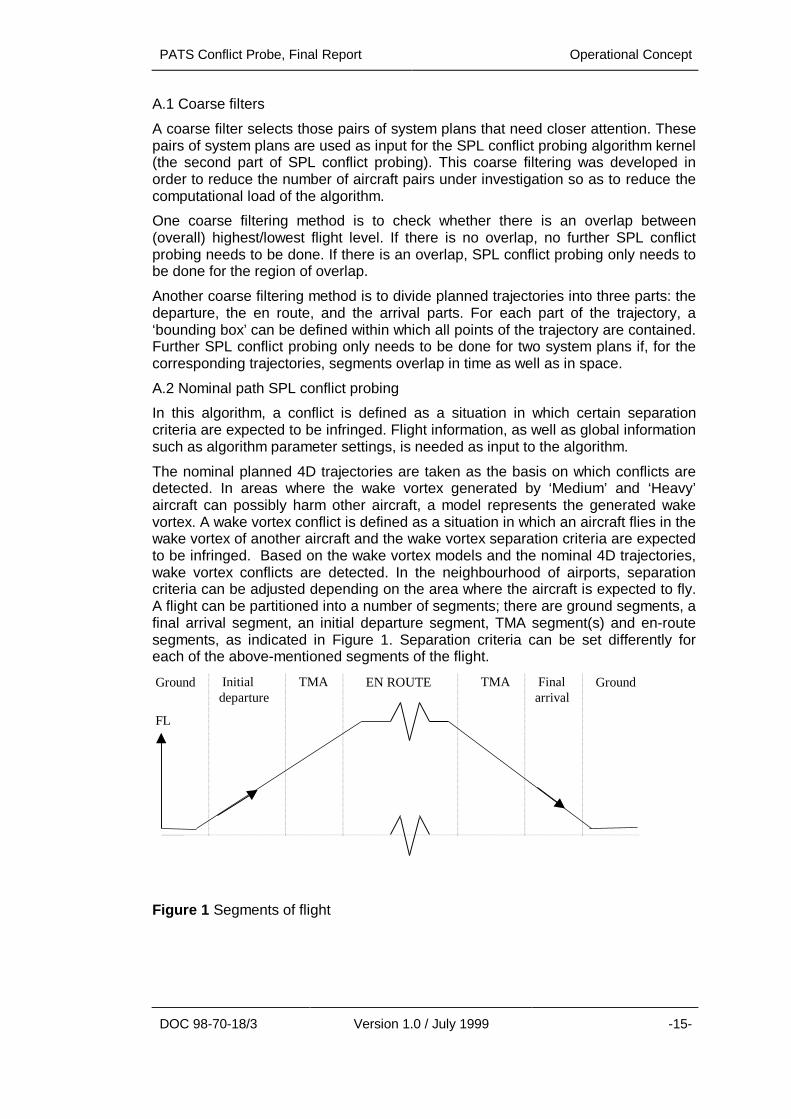
The nominal planned 4D trajectories are taken as the basis on which conflicts aredetected. In areas where the wake vortex generated by ‘Medium’ and ‘Heavy’aircraft can possibly harm other aircraft, a model represents the generated wakevortex. A wake vortex conflict is defined as a situation in which an aircraft flies in thewake vortex of another aircraft and the wake vortex separation criteria are expectedto be infringed. Based on the wake vortex models and the nominal 4D trajectories,wake vortex conflicts are detected. In the neighbourhood of airports, separationcriteria can be adjusted depending on the area where the aircraft is expected to fly.A flight can be partitioned into a number of segments; there are ground segments, afinal arrival segment, an initial departure segment, TMA segment(s) and en-routesegments, as indicated in Figure 1. Separation criteria can be set differently foreach of the above-mentioned segments of the flight.
FL
EN ROUTE Ground Finalarrival
TMA TMA Initialdeparture
Ground
Figure 1 Segments of flight

Operational Concept PATS Conflict Probe, Final Report
-16- Version 1.0 / July 1999 DOC 98-70-18/3
A.3 Protection zone SPL conflict probing
In this algorithm, a conflict is defined in the same way as it was defined in theprevious section. Also, as for the nominal path SPL conflict probing algorithm, flightinformation, as well as global information such as algorithm parameter settings, isneeded as input to the algorithm. The difference between the approaches describedin A.2 and A.3, is the way in which a conflict is detected.
The protection zone SPL conflict probing algorithm starts with a search for conflictsin the vertical direction; if one is found, a search is made in the horizontal plane.
Every flight is divided into several segments (parts between different way points)where, for each way-point, both an Expected Time Over (ETO) and an expectedflight level are specified. Thus, for every segment, a flight level band can bedefined. The vertical part of the conflict detection algorithm consists of a search forthe segments of each flight where a conflict is possible with another flight based onthe flight level bands. This is the case if the flight level bands overlap or, areseparated by less than the required separation criteria. Figure 2 shows how theflight level bands are computed from the given flight levels for an aircraft crossingthe Dutch Flight Information Region (FIR.)
Figure 2 Protection zone in the vertical plane
In this example, an aircraft enters the FIR in one sector, then crosses anintermediate sector (e.g. the SPY/PAM area) and finally exits the FIR in yet anothersector.
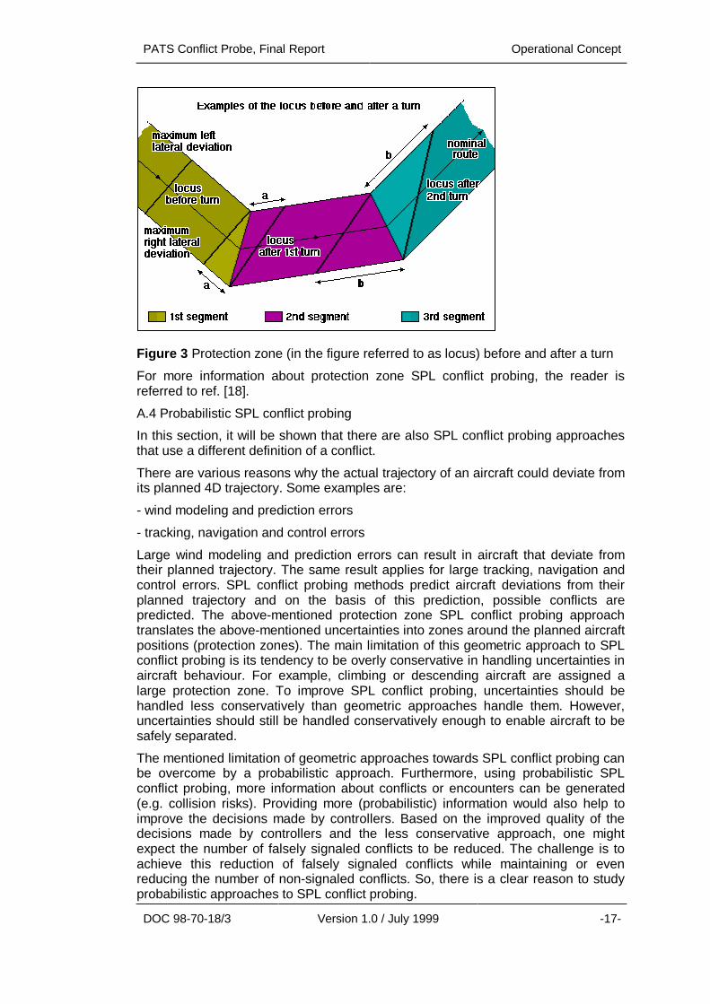
For the horizontal conflict calculation, certain inaccuracy parameters are introduced,especially for the ground speed and the lateral deviation from the nominal routes.The result of this is that, for every moment of a flight, an aircraft is expected to be ina certain region of airspace. These regions are referred to as protection zones. Theprotection zones for each pair of flights are compared to each other. A conflict issignaled if the protection zones of two aircraft overlap or are closer to each otherthan the separation criteria dictate. Figure 3 shows an example of the protectionzones in the horizontal plane for a single flight.
PATS Conflict Probe, Final Report Operational Concept
DOC 98-70-18/3 Version 1.0 / July 1999 -17-
Figure 3 Protection zone (in the figure referred to as locus) before and after a turn
For more information about protection zone SPL conflict probing, the reader isreferred to ref. [18].
A.4 Probabilistic SPL conflict probing
In this section, it will be shown that there are also SPL conflict probing approachesthat use a different definition of a conflict.
There are various reasons why the actual trajectory of an aircraft could deviate fromits planned 4D trajectory. Some examples are:
- wind modeling and prediction errors
- tracking, navigation and control errors
Large wind modeling and prediction errors can result in aircraft that deviate fromtheir planned trajectory. The same result applies for large tracking, navigation andcontrol errors. SPL conflict probing methods predict aircraft deviations from theirplanned trajectory and on the basis of this prediction, possible conflicts arepredicted. The above-mentioned protection zone SPL conflict probing approachtranslates the above-mentioned uncertainties into zones around the planned aircraftpositions (protection zones). The main limitation of this geometric approach to SPLconflict probing is its tendency to be overly conservative in handling uncertainties inaircraft behaviour. For example, climbing or descending aircraft are assigned alarge protection zone. To improve SPL conflict probing, uncertainties should behandled less conservatively than geometric approaches handle them. However,uncertainties should still be handled conservatively enough to enable aircraft to besafely separated.
The mentioned limitation of geometric approaches towards SPL conflict probing canbe overcome by a probabilistic approach. Furthermore, using probabilistic SPLconflict probing, more information about conflicts or encounters can be generated(e.g. collision risks). Providing more (probabilistic) information would also help toimprove the decisions made by controllers. Based on the improved quality of thedecisions made by controllers and the less conservative approach, one mightexpect the number of falsely signaled conflicts to be reduced. The challenge is toachieve this reduction of falsely signaled conflicts while maintaining or evenreducing the number of non-signaled conflicts. So, there is a clear reason to studyprobabilistic approaches to SPL conflict probing.
Operational Concept PATS Conflict Probe, Final Report
-18- Version 1.0 / July 1999 DOC 98-70-18/3
The probabilistic approach towards SPL conflict probing discussed here wasdeveloped at NLR (see refs. [19], [20] and [21]). NLR has developed a method tocalculate collision risk. Since information about collision risk is available, a collisionrisk threshold (the maximum allowed collision risk) can replace separation criteriaas the means to detect conflicts. This is the case in the NLR probabilistic SPLconflict probing approach: a conflict is defined as a situation in which the collisionrisk infringes some collision risk threshold. SPL conflict probing is done based onthe calculated collision risk.
The theory behind the calculation of collision risk will only be mentioned briefly. Theconflict (or collision) prediction model at NLR is based on a generalized version ofICAO's collision risk (probability) approach (based on the Reich-model, see ref.[22]). The generalizations were required since the Reich-model was derived underrather restrictive assumptions.
The generalized Reich model needs a characterization of the joint probabilitydensity function of relative position and velocity as input. As output of the model, thecollision risk for an aircraft pair is generated. For a more elaborate treatment, thereader is referred to ref. [19].
Since the PATs TP does not provide information about the uncertainties associatedwith the planned flight path (planned 4D trajectory), the CP should determine theseuncertainties for itself. In the PHARE concept, all aircraft are expected to follow theplanned 4D trajectories that are generated by the TP. If an aircraft can not follow itsplanned 4D trajectory autonomously, it can be supported by advisories from theground. So, in the PHARE concept, aircraft are assumed to be close to theirplanned 4D positions at all times. Extending this line of thinking to determining theuncertainties of the planned 4D trajectories, the uncertainties in the position andspeed of aircraft can be assumed constant as a function of time.
Collision risk is a measure of the probability that two aircraft will collide in some timeinterval. For the NLR probabilistic SPL conflict probing approach, joint probabilitydensity functions of positions and velocities of an aircraft pair are assumed to bepredicted first. (Uncertainties are read from a datafile that is maintained by the CP).Then the joint probability density function of the relative position and velocity of theaircraft pair should be calculated. Finally, the collision risk for the aircraft pair shouldbe calculated using the generalized Reich model. Since the uncertainties areassumed to be constant, the collision risk only needs to be evaluated for a pair ofsystem plans if one of the planned 4D trajectories is changed.
Collision risk itself is not the kind of information that is useful to an Air TrafficController because it is difficult to interpret. A possible approach for the usage ofcollision risk information is given here.
Collision risk can be translated into three possible categories of conflicts, using twothresholds as follows. The collision risk can be used to detect conflicts by setting anupper threshold for collision risk. Pairs of system plans for which the collision riskinfringes the upper threshold (collision risk larger than upper threshold), areclassified as certain conflict situations. A lower threshold can be set below theupper threshold to detect situations that have potential to grow into a conflict. Pairsof system plans for which the collision risk is smaller than the upper threshold andlarger than the lower threshold, are classified as potential conflict situations. Pairs ofsystem plans for which the collision risk is smaller than the lower threshold, areclassified as no conflict situations. The HMI part of the probabilistic SPL conflictprobing approach has not been elaborated.

PATS Conflict Probe, Final Report Operational Concept
DOC 98-70-18/3 Version 1.0 / July 1999 -19-
B. Area Conflict Probing
Area conflict probing, like the SPL conflict probing discussed in A.1 to A.5, consistsof two parts. The first part of area conflict probing is the selection of those systemplans that need closer attention with respect to possible area conflicts (using thesame procedure as that was described for SPL conflict probing). A coarse filterdoes this part of the area conflict probing. In the second part, the area conflictprobing algorithm compares a system plan with a restricted area and calculatesarea conflict information. A system plan contains a description of the 4D trajectorythat the aircraft is supposed to fly, together with general flight information. Detailedsystem plan information will be given in the next section. A restricted area isdescribed by its upper and lower flight level and an ordered list of 2D points thatdescribes the boundary of the area in the horizontal plane.
In this algorithm, an area conflict means that an aircraft is expected to fly through arestricted area. The segment of the 4D trajectory that is inside the restricted areacan be generated as output of the algorithm. Since, in the PD systems, there wereno restricted areas, this algorithm was not used during the PD trials.
2.2. CONTEXT DESCRIPTION
This section describes the external entities that are relevant to the CP and theirinterfaces. For a more extended treatment the reader is referred to refs. [23] and[24].
The basic functionality of the CP is to probe conflicts in any 4D SPL that isprovided, with relation to other SPLs and to restricted areas. The CP shall providefull conflict reports on aircraft that are within the area of responsibility, using ActiveSPLs and Alternative System Plans. Active and Alternative SPLs shall be suppliedby ATC simulation platform servers or PATs.
Conflicts may occur between two SPLs, or between one SPL and a restricted areasuch as a Temporary Restricted Area (TRA).
Any ATC simulation platform server or PATs tool has the possibility to use the CP toevaluate one or more Alternative SPLs. Single Alternative SPLs are compared to allActive SPLs in the system that do not apply to the same flight as the AlternativeSPL. All Alternative SPLs in a set of Alternative SPLs are compared with each otherand with all active SPLs that do not apply to any of the flights in the set ofAlternative SPLs.
Following the client-server paradigm, the CP performs its task autonomously. Themaintenance of conflict information is the full responsibility of the CP. To determineif a conflict exists, the CP acts as a client that calls different ATC simulation platformservices and PAT services. Clients use the conflict information of the CP, either bydirectly asking the CP for specific conflict information (action from client,synchronous) or are informed by the CP after taking a subscription to a certain typeof conflict information (action from CP, asynchronous). In both cases, the CP actsas a Server.
Operational Concept PATS Conflict Probe, Final Report
-20- Version 1.0 / July 1999 DOC 98-70-18/3
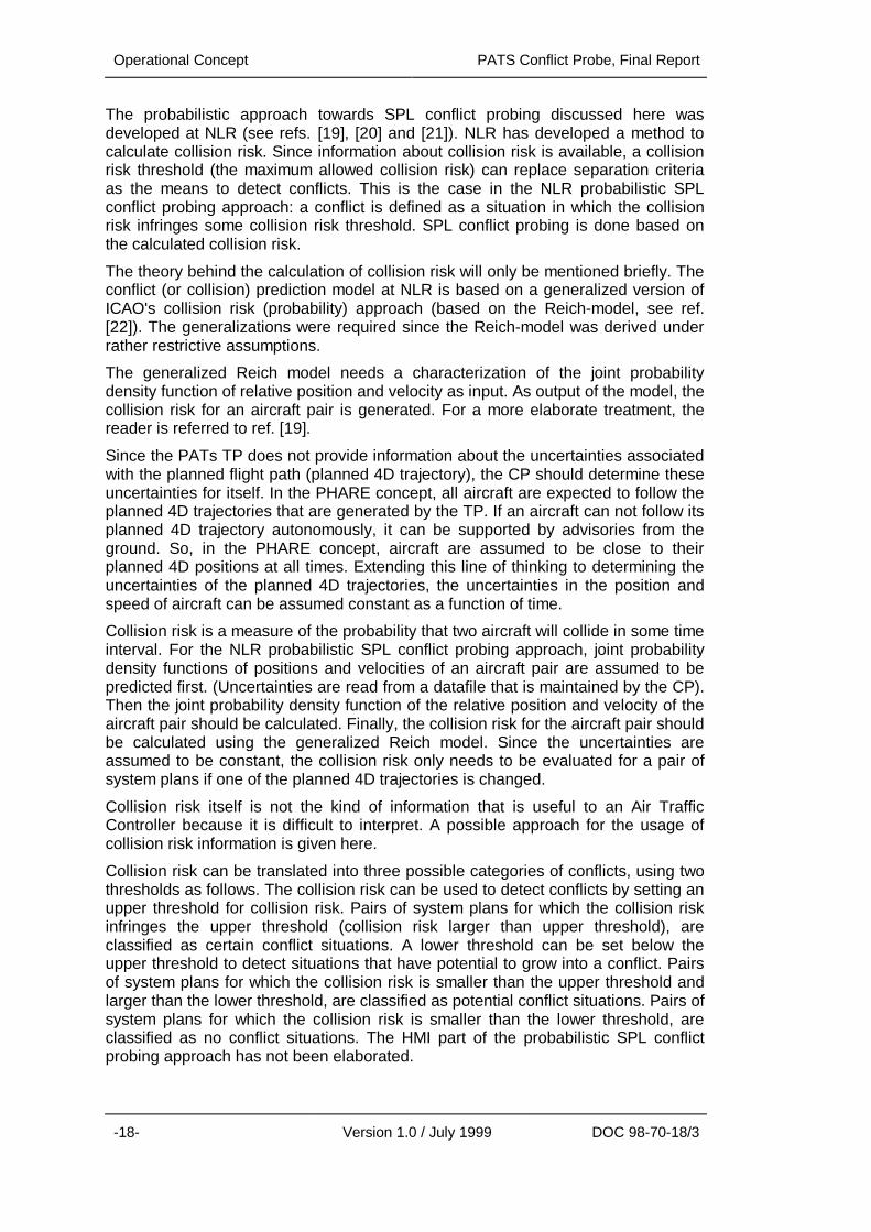
2.2.1. Sub-system Terminators
GHMI
FLIGHTSERVER
ARRIVALMANAGER
NEGOTIATIONMANAGER
DEPARTUREMANAGER
AIRSPACESTRUCTURE
SERVER
CONFLICTPROBE
Active SPL event
SubscriptionConflict Event
Area Event
AlternativeSPL info
Conflict infoSubscription
SubscriptionConflict info
AlternativeSPL info
Subscription
Conflict info
AlternativeSPL info
Figure 4 Context diagram of the Conflict Probe
For the description of the context of the CP, the Yourdon environmental model isused (see ref. [25]). The diagram indicates the entities that are external to the CP.The CP itself is drawn as a circle (Yourdon: process 0). External entities thatcommunicate with the CP are drawn as boxes (Yourdon: terminators); they must beregarded as fixed entities in the environment of the CP. Data flowing to and fromthe CP are shown as arrows that indicate the direction of data flow.
The list of external entities and external interfaces is a generic one. On differentATC simulation platforms, the functionality of the servers may differ slightly. Theexternal entities that are identified with tools in the PATs cluster are the ArrivalManager, the Departure Manager, and the Negotiation Manager.
An examination of events that trigger the CP to act (input events) and that aresignalled by the CP (output event) will be given next. First, the input events areenumerated. For every input event, the reasons that could cause it are indicated.Second, the output events are enumerated. For every output event, the inputevent(s) that could have lead to it are indicated.Six input events are distinguished:1. A new Active SPL is received. This event occurs when a new aircraft enters the
system.2. An updated Active SPL is received. This event occurs when an existing Active
SPL is changed for one reason or another.3. An Active SPL has ended. This event occurs when a flight has landed or
otherwise left the system.4. An Alternative SPL is received to prepare it for inclusion in the system as an
Active SPL. This event occurs when an ATC simulation platform server or PATrequests the CP to evaluate an Alternative SPL.
5. A restricted area becomes active. The Airspace Structure Server triggers thisevent.
6. A restricted area becomes inactive. The Airspace Structure Server triggers thisevent.
PATS Conflict Probe, Final Report Operational Concept
DOC 98-70-18/3 Version 1.0 / July 1999 -21-
Eight output events are distinguished:
1. A new conflict between Active SPLs is detected. This event can be caused byinput event 1.
2. A conflict between Active SPLs is updated. This event can be caused by inputevent 2.
3. A conflict between Active SPLs has ended. This event can be caused by inputevents 2 or 3.
4. A conflict between an Alternative SPL and an Active SPL is detected. This eventcan be caused by input event 4.
5. A new conflict between an Active SPL and a restricted area is detected. Thisevent can be caused by input events 2 or 5.
6. A conflict between an Active SPL and a restricted area is updated. This eventcan be caused by input event 2.
7. A conflict between an Active SPL and a restricted area has ended. This eventcan be caused by input events 2, 3, or 6.
8. A conflict between an Alternative SPL and a restricted area is raised. This eventcan be caused by input event 4.
2.2.2. Sub-system Inputs
Input to the CP is the data that is needed to generate information on possibleconflicts. Most input data is obtained from ATC simulation platform servers. SomePATs are capable of creating Alternative SPLs; they also may provide input (one ormore Alternative SPLs) to the CP. The following ATC platform servers areidentified: the Flight server and the Airspace Structure server. The following PATsare identified: the Arrival Manager, the Departure Manager, and the NegotiationManager.
• The Flight Server deals with all the system plans of the ground system. Itmaintains all 4D-trajectory data for the system. It provides the CP with all ActiveSPLs within the simulator that are within the area of interest.
• The Airspace Structure Server deals with the airspace structure data availablefor both the air system and the ground system. It provides the CP with data onrestricted areas.
• The Arrival Manager provides assistance to the controller in handlingapproaching traffic. It provides the CP with Alternative SPLs.
• The Departure Manager provides optimised departure schedules and advisoriesto the departure controllers. It provides the CP with Alternative SPLs.
• The Negotiation Manager is a tool for managing, by means of electronic co-ordination, trajectory negotiation both between the aircraft and the ATC groundsystem and between members of the ground system. It provides the CP withAlternative SPLs.

Operational Concept PATS Conflict Probe, Final Report
-22- Version 1.0 / July 1999 DOC 98-70-18/3
2.2.3. Sub-system outputs
Output from the CP is a conflict report. Any ATC simulation platform server or PATcan obtain conflict information from the CP. It is believed that the following entitiescan benefit from the conflict information:
- The GHMI of the Air Traffic Controller;
- The AM, providing assistance to the controller in handling approachingtraffic;
- The DM, providing optimised departure schedules and advisories to thedeparture controllers;
- The NM, managing, by means of electronic co-ordination, trajectorynegotiation both between the aircraft and the ATC ground system andbetween members of the ground system.
2.3. DEVELOPMENT PROCESS
2.3.1. History of Tool Development
The development of the Conflict Probe was by means of a stepwise progressionthrough a series of PDs. PD/1 took place in late 1995; PD/2 took place in June1996, and PD/3 took place in 1998.
PD/1, hosted by NATS, was based on an en-route scenario. An initial version of theCP was developed and integrated with other tools within a framework called CMS.The scope of the CP tool was to detect conflicts in the en-route sector. This versionof the CP was based on protection zone SPL conflict probing as discussed in theprevious section. The NLR-developed Area Conflict Detection (ACOD) algorithmswere the basis for this protection zone SPL conflict probing.
PD/2, hosted by DLR, was based on a TMA scenario. The algorithm of the initialversion of the CP was replaced by a nominal path SPL conflict probing algorithm.Additional capability to handle wake vortex and other aspects relevant to the TMAwere also developed.
PD/3, hosted by NLR, EEC and CENA, was based on a multi-sector scenario. Thisscenario included the full route of aircraft from take off to touch down. Additional tothe existing PD/2 version of the CP, area conflict probing algorithms wereincorporated in the PD/3 version of the CP.
2.3.2. Why it was developed that way
The reason for the development of an initial CP version based on protection zoneSPL conflict probing was that NLR already had experience with this kind of conflictprobing. Protection zone SPL conflict probing algorithms were developed withinACOD. The ACOD tool is part of the Amsterdam Advanced ATC (AAA) system - theATC system that became operational in 1998 at the Dutch civil ATC authorities.ACOD was especially designed for en-route traffic, so the SPL conflict probingalgorithms were very useful for the development of the PATs CP for PD/1.
For PD/2, the TMA traffic was considered. This traffic is much more dynamic thanthe en-route traffic that could easily be handled by the PD/1 version of the CP.However, since PD/2 traffic demands were much more dynamic, another SPLconflict probing algorithm was developed. This nominal path SPL conflict probingalgorithm is capable of handling the dynamic TMA traffic. Furthermore, wake vortexand other TMA related aspects were incorporated in the PD/2 version of the CP.

PATS Conflict Probe, Final Report Operational Concept
DOC 98-70-18/3 Version 1.0 / July 1999 -23-
For PD/3, en-route traffic as well as TMA traffic was considered. The developmentof the PD/3 version of the CP was mainly focussed on optimising the nominal pathSPL conflict probing algorithms as they were developed for PD/2. Additionally,algorithms for area conflict probing were developed for PD/3 within the CP.
2.3.3. Dropped ideas and concepts
It turned out that the concept of protection zone SPL conflict probing inside the TMAdoes not work due to assigning large protection zones to climbing or descendingaircraft.
Another dropped idea within the PATs project is the presentation of probabilisticconflict information (collision risk) to controllers. Controllers do not want to see therisk on a collision, they want to see whether a situation is a conflict or not.

PATS Conflict Probe, Final Report
-24- Version 1.0 / July 1999 DOC 98-70-18/3
This page left intentionally blank

PATS Conflict Probe Final Report Requirement Description
DOC 98-70-18/3 Version 1.0 / July 1999 -25-
3. REQUIREMENT DESCRIPTION
In this section, an overview of the requirements of the PATs CP as described in ref.[26] is given.
3.1. USER REQUIREMENTS
The PATs CP shall be used by Air Traffic Controllers. The interface (GHMI) towardsthe ATCo will not be developed within the CP project, but will be developed in theGHMI project. The interaction between the CP and the ATCo shall take placethrough the GHMI.
The PATs CP shall assist ATCos to detect possible conflicts between aircraft inaccordance with certain safety rules.
The PATs CP shall assist ATCos to detect possible conflicts between aircraft andrestricted areas.
The “real world” (Active System Plans) as well as “what-if” (Alternative SystemPlans) situations shall be probed for possible conflict situations.
3.2. FUNCTIONAL REQUIREMENTS
The PATs CP shall probe system plans in such a way that it will detect any conflictthat may occur between aircraft. For this, it shall compare the Active System Planswith each other.
Furthermore the PATs CP shall be able to probe Alternative System Plans. For this,it shall compare Alternative System Plans with each other and it shall comparesingle Alternative System Plans with the Active System Plans of all other flights.
The PATs CP shall probe System Plans and restricted areas in such a way that itwill detect any conflict that may occur. For this, it shall compare Active andAlternative System Plans with restricted areas.
The PATs CP shall generate messages containing all relevant information ondetected possible conflicts.
3.3. IMPLEMENTATION DEPENDENT REQUIREMENTS
3.3.1. Integration
The tool shall be capable of being integrated as a tool in each of the following ATCsimulator environments:
• PARADISE, available at every site (the integration is responsibility of CP /PARADISE developers);
• PD/3 (PHARE Demonstration/3) at NLR, Amsterdam, CENA, Athis-Monsand EEC, Brétigny (integration is PD/3 responsibility).
The tool shall be implemented in such a way that transportation to any of the abovementioned systems is performed with minimum effort. To enable this, a client/serverarchitecture will be used as far as possible. Also the use of an ISO/ANSI specifiedprogramming language has a strong preference.
Requirement Description PATS Conflict Probe, Final Report
-26- Version 1.0 / July 1999 DOC 98-70-18/3
3.3.2. Client/server architecture
The tool shall be developed according to a client/server architecture, such thatcommunications will be allowed to occur either synchronously or asynchronously. Inthis way, delayed responses to requests for data made by the tool shall not causeprocessing of other inputs to be delayed.
3.3.3. Platform independent
The tool shall be developed in a platform independent manner, such that there is noreliance on any underlying operating system. The developed software shall notmake references to platform-specific functions.
3.3.4. Configuration data source
The tool shall be capable of accepting configuration data from servers within thesimulation platform and / or a configuration file. The tool shall be developed with anApplication Programming Interface (API) that allows configuration data to be passedin during initialisation. Additionally, the tool shall provide suitable routines forreading all required configuration data from a file. These routines shall be used bydefault. This provides the integrator with the option of reprogramming part or all ofthe configuration data interface so that configuration data can be obtained fromother servers within the integrated system, rather than the file provided with the tool.
PATS Conflict Probe, Final Report Implementation
DOC 98-70-18/3 Version 1.0 / July 1999 27
4. IMPLEMENTATION
In this section, it will be explained how the PATs CP was developed andimplemented. The environment in which the PATs CP was developed will bedescribed. Problems that were encountered during the implementation of the CP aswell as the reasoning behind their solutions will be given. Finally, some lessonslearnt will be given.
4.1. HOW DEVELOPED
The development of the CP was aimed at providing
• a tool box function in composition with other PATs,
• a research tool in the area of conflict probing,
• a tool that can be easily adapted to meet new (research) requirements,
• a tool that can be easily integrated in several ATC environments.
In order to reach the above goals, the interfaces to other PATs and servers areevent based. Other entities are given the opportunity to use the CP as a server thatprovides information on request. To support structured programming techniques,the tool has been implemented in Ada. Furthermore, the tool has been developedusing client/server techniques.
The tool algorithms were first implemented and tested in a mathematicalprogramming environment (MATLAB). After verification, the algorithms wereimplemented in Ada. The shell around the algorithms was directly implemented inAda.
Early in 1996, all PATs project participants received a workstation fromEUROCONTROL that was to be used for PATs development. The intention wasthat all PHARE partners would use the same development hardware and software,making integration and software exchange between the partners easier.
To increase the possibilities to test the CP at NLR, a mechanism was implementedthat enables the CP to be run stand-alone. This mechanism is referred to as theFast Time Environment (FTE). In this FTE, the tool can process defined scenarioswithout running them in PARADISE or other specific platforms.
Test scenarios can be defined and prepared either using a specific platform such asNARSIM or PARADISE, or by hand. The tool can directly read those scenarios bymeans of the Event Generator. Using this mechanism, scenarios can be processedat high speed since no intervention from other tools or time synchronisation isneeded. This way, the tool can be tested as a stand-alone process. It is notnecessary to start PARADISE or any other PATs tools. This reduces both theamount of time needed to start the CP up as well as the amount of computerresources needed. As a result, test runs can be done in significantly less time thanwould otherwise be needed when testing in PARADISE or NARSIM. RepresentativeFTE test runs could be finished within 1 minute, as opposed to similar test runs inPARADISE which would take 20 minutes or more. Still, test runs using PARADISEor another simulation platform had to be executed in order to test the correctbehaviour of the tool with respect to interfaces and client/server connections.

Implementation PATS Conflict Probe, Final Report
-28- Version 1.0 / July 1999 DOC 98-70-18/3
4.2. TECHNICAL ENVIRONMENT
By using ‘remote login’ or a ‘telnet session’, the PATs development workstation(‘Paradise’) can be connected to from any NLR workstation or PC that is connectedto the NLR computer network. The Paradise operating system is Solaris.
On the Paradise workstation, two Ada compilers were available. The Adadevelopment environment used by all PHARE partners for their tool developmentwas the VERDIX Ada development environment, version number 2.1. It consists ofa complete set of software development tools, including a compiler, linker, anddebugger. A drawback is that there was only one licence available for this compiler,so only one developer could compile his or her code at the same time. To overcomethis drawback, the freely available GNU Ada compiler (gnat) was installed on theplatform. This compiler could be used by an unlimited number of users at the sametime. However, no debugging tools for this compiler were installed on the platform.
Other tools installed on the platform included a source code Revision ControlSystem (RCS), a C++ development environment, and several GNU tools (such asGNU ‘make’ and ‘gzip’). Also installed on the platform was the PATs simulationplatform PARADISE, which was used for testing and evaluating the PATs tools.
Since the beginning of the development of the PATs, PARADISE has beendeveloped in parallel. The development of PARADISE progressed through variousversions. Each new version of PARADISE demanded a lot of integration effort fromthe tools. The goal was to obtain a version of PARADISE where all tools wereintegrated on such that the tools could be tested and evaluated as a cluster. Thisgoal was never reached because of the continual changes to PARADISE.
The CP tool was successfully integrated into different simulation platforms. Thesesimulation platforms are NARSIM at NLR, ESCAPE at EEC and DAARWIN atCENA.
4.3. PERFORMANCE ISSUES
During the development of the CP, several performance tests have been executedusing the facility to run the CP stand alone (FTE). The results of these tests weresuch that no performance problems are expected for the CP, when run in real-timesystems.
During the further development of the CP, performance issues had lower prioritythan the fulfilling of the functional requirements. Until now, there have been nomessages from the PDs and IOCPs that the CP had problems with theperformance.
4.4. PROBLEMS FOUND AND SOLVED
Ground conflicts
During some real-time trials, the problem occurred that the CP detected conflictsbetween aircraft when they were already planned on the ground. This problem wassolved by the introduction of a context sensitivity module. This module takes theposition of the aircraft into account by dividing the 4D trajectory in segments(ground segment, final arrival segment, initial departure segment, TMA segment(s)and en-route segment). This is also described in section 2.1.2, A.2.
Inconsistency with CT
Within the PATs CT, a conflict detection mechanism was also developed. Theconflict detection mechanism developed by the CT development team is based on adifferent conflict detection approach than the HIPS and the CP ones. The solution to

PATS Conflict Probe, Final Report Implementation
DOC 98-70-18/3 Version 1.0 / July 1999 -29-
this inconsistency problem is that the problems detected by the CT conflictdetection mechanism are defined as interactions instead of conflicts. Different useof interactions and conflicts avoided inconsistencies between the conflict detectionmechanisms of the CP and the CT.
4.5. UNSOLVED PROBLEMS
Inconsistency with HIPS
A conflict detection mechanism was also developed for the PATs HIPS. This conflictdetection module was developed, because the HIPS is an interactive conflictresolution tool; an Air Traffic Controller can re-define a representation of a 4Dtrajectory that is in conflict with another 4D trajectory by dragging it until the conflictdisappears. Therefore, the conflict detection mechanism had to be very fast and theHIPS developers thought that the connection between the HIPS and the CP wouldbe too slow. However, by introducing a conflict detection module in the HIPS (whichis different from the conflict detection in the CP), a consistency problem has beencreated. To avoid any inconsistency, the HIPS should detect all conflicts alsodetected by the CP. As can be seen in section 6, this inconsistency problem wasnot solved during the PATs project.
4.6. LESSONS LEARNT
Planning issue
The purpose of the PATs project was that the tools would be developed in asimulation environment called the CMS. If all tools had been integrated on the samesimulation platform (referred to as PARADISE), test runs could have been madeand the PATs cluster could have been evaluated and validated. However, thedevelopment of the simulation environment CMS was planned parallel to thedevelopment of the tools. The result of this parallel approach was that a lot of timewas needed for the tool developers to integrate the tools in successive CMSversions. A lesson learnt is that the development of the simulation environment, inwhich ATC tools can be evaluated and validated, should be done before thedevelopment of the tools themselves start.
Consistency issue
At several places within the ATC simulation environment, conflict definitions areused.
For successful development of an ATC tools cluster, these conflict definitions haveto be consistent.
Development approach
It turned out that the approach followed by PATs was a tool driven approach ratherthan a concept driven approach. With a tool driven approach, the tools aredeveloped almost independently of each other. Only after some development workwas finished it was noticed that some tools had incorporated conflictingfunctionalities or had overlap in functionalities. In general, the tools were notconsistent with each other.
For a successful development of an ATC tools cluster, a concept driven approachwould have been better. All the tools should have been developed according tocommon concepts, which everybody had agreed upon, and the various activitiesshould have been geared to one another to a much greater extent than was donewithin this project.
Implementation PATS Conflict Probe, Final Report
-30- Version 1.0 / July 1999 DOC 98-70-18/3
This page left intentionally blank
PATS Conflict Probe, Final Report Usage of Tool
DOC 98-70-18/3 Version 1.0 / July 1999 31
5. USAGE OF TOOL
In this section it will be explained how the PATs CP has been used. The expectedusers of the CP are Air Traffic Controllers and the technical people who areresponsible for integrating and maintaining the tool in their system.
5.1. OPERATIONAL USAGE
In this section the operational usage of the CP is considered; the users areconsidered to be a number of the other PATs and the controllers. The usage of theCP as described in the final reports of PD/1 (see ref. [27]) and PD/2 (see ref. [28])are given as well as the usage that is envisaged for PD/3.
Besides the three mentioned PD’s, there have been performed a number ofadditional trials wherein the CP participated. These trials were named PD/1+ (seeref. [31]), PD/1++ (see ref. [32]), PD/2+ (see ref. [33]) and PD/3 Continuation. In thissection, the purposes of these additional trials and the usage of the CP within thesetrials is briefly described. It has to be noted that re-integration of the CP in PD/2+was straightforward, as they had been used in PD/1, and their external interfaceswere fairly simple (see ref. [33]).
PD/1, hosted by NATS, had an en-route scenario. The PATs that were used in PD/1were the TP, the CP, the FPM and the HIPS.
In PD/1, the CP operated automatically on each new trajectory in the flightdatabase, comparing it with every other trajectory to identify any loss of separation.If a conflict is found, the CP reports the conflict, mentioning the two aircraft involvedand including details such as the start time of the conflict and closest point ofapproach. This information is thus available to other tools and to the GHMI fordisplay to the controller. The CP also passes information to the tools and GHMIwhen a conflict is cleared allowing the system displays to be updated.
Components of the GHMI that use information from the CP are:
1. The Conflict Risk Display (CRD) - which shows all potential losses of separationbetween aircraft in terms of how soon they could occur and what the minimumseparation would be.
2. The Conflict Zoom Window (CZW) - which shows a forecast of the aircraft tracksfor a particular conflict at the time of closest approach.
Detected conflicts could then be solved using the HIPS.
The PD/1+ trial took place in January and February 1997 at the Air TrafficManagement Development Centre, Hurn. The main aim of the PD/1+ trial was tocompare workload and tool use between PD/1 and a modified PD/1 system. Thetrial was the culmination of the NATS PD/3 IOCP Project. The PATs used duringthe PD/1+ trial were the TP, the CP, the FPM and the HIPS.
The NATS PD/1++ project was a continuation of the previously conducted PD/1 andPD/1+ trials and was specifically designed to begin the process of exploring theintroduction of the PHARE tools and operational concept within alternative en-routeairspace structures. The PD/1++ trial took place in late August 1998 at NATS’ AirTraffic Management Development Centre, Hurn. The main aim of the PD/1++ trialwas to examine the effects on controller workload, airspace capacity, quality ofservice and the usability of the ATC system of the introduction of alternativeairspace structures and alternative operating practices. The PATs used during thePD/2+ trial were the CP, the FPM, the HIPS and the TP.
Usage of Tool PATS Conflict Probe, Final Report
-32- Version 1.0 / July 1999 DOC 98-70-18/3
The usage of the CP within PD/1+ and PD/1++ is the same as the usage of the CPin PD/1.
PD/2, hosted by DLR, was a TMA scenario. The PATs that were used in PD/2 werethe TP, the CP, the FPM, the NM, and the AM.
In PD/2, conflicts between planned trajectories had to be solved manually by thecontroller because HIPS was not available. The CP compared the new trajectory ofan aircraft entering the simulation with all trajectories already stored within the flightdatabase of the ground system. Any violation of separation criteria like radarseparation or wake vortex separation was identified and displayed as a function ofposition and time. In case of a planning conflict, the CRD popped up on the PlanView Display (PVD). In this window the callsigns of the conflicting aircraft werelisted together with an indication of the time remaining before the start of the conflict(specified in minutes) and the minimum separation during the conflict time(specified in nautical miles). Optionally, the labels of the associated aircraft werehighlighted on both the PVD and Arrival Management Display (AMD).
The CP was triggered by the AM when the sequencer (the functionality within theAM that provides sequencing and scheduling) triggered the CP to check alternativetrajectories for conflicts.
The NATS PD/2+ project was designed to gain a more thorough understanding ofarrival management concepts and interactions between controller positions, thanhad been possible during the PD/2 trial. Specifically, the aim of the project was touse the PD/2 PATs, primarily the AM, with further development to achieve fullfunctionality. Additional enhancements included: staffed en route sectors; missedapproaches; holds and arrival rates approaching runway capacity. Theseenhancements were to be evaluated through the ‘PD/2+ trial’, a real-time simulationon the NATS Research Facility.
The PD/2+ trial took place in September and early October 1997 at the Air TrafficManagement Development Centre, Hurn. The PATs used during the PD/2+ trialwere the TP, the CP, the FPM, the HIPS and the AM.
The usage of the CP within PD/2+ is the same as the usage of the CP in PD/2.
PD/3, hosted by NLR, EEC and CENA, was a multi-sector scenario. This scenarioincluded the full route of aircraft from take off to touch down.
Since the usage of the CP had to be the same for all sites where the PD/3 trialswere supposed to be held, the usage will be explained for one site only. The PATsthat were used for the PD/3 trials at NLR, were the TP, the NM, the CP, the FPM,the AM and the HIPS.
In PD/3, the CP usage was a mixture of the PD/1 usage and PD/2 usage. The CPcompared all new or updated trajectories entering the system, to check for conflicts.In case of a planning conflict, the conflict could be seen in the CRD. In this window,the callsigns of the conflicting aircraft were listed together with an indication of thetime ahead of a conflict (minutes) and the minimum distance at conflict time(nautical miles). Optionally, the labels of the associated aircraft were highlighted onboth the PVD and AMD. The HIPS could be used to solve the conflict and the CZWcould be used to zoom into the situation where the closest approach was expectedto happen.
The CP was triggered by the AM to check alternative trajectories for conflicts. Incase of conflicts, the AM replanned trajectories.

PATS Conflict Probe, Final Report Usage of Tool
DOC 98-70-18/3 Version 1.0 / July 1999 -33-
5.2. TECHNICAL USAGE
The CP tool is supplied as a set of Ada83 source files that are intended forintegration into an air traffic control simulation system. To enable easy integration, astrict separation between platform specific packages and core functionalitypackages has been made. Integration teams need only change the platformdependent packages, which contain client/server mechanisms that are typical forthe ATC simulation platform and conversion routines to convert platform dependentdata to and from CP internal data. The core functionality part remains unchanged,thus ensuring a consistent working of the tool across all platforms.
The source code is provided with a number of Ada83 API packages that are usedby system integrators as an interface between the tool and the software that the toolis being integrated into.
The source code is delivered as a single compressed file that is created using the'gzip' and 'gtar' gnu programs, executed under the UNIX operating system. Thesource code should be uncompressed using the 'gunzip' program and unpackedusing the 'gtar' program using a specific set of command line options. Alternatively,the standard UNIX 'tar' utility may be used.
The CP tool is supplied with suitable 'make' files for each ATC simulation platform.It is intended that the tool should be built using the 'gmake' gnu program, runningwithin the UNIX operating system.
The User Guide (see ref. [29]) provides a full description of the technical usage ofthe software.

PATS Conflict Probe, Final Report
DOC 98-70-18/3 Version 1.0 / July 1999 34
This page left intentionally blank
PATS Conflict Probe, Final Report Results
DOC 98-70-18/3 Version 1.0 / July 1999 -35-
6. RESULTS
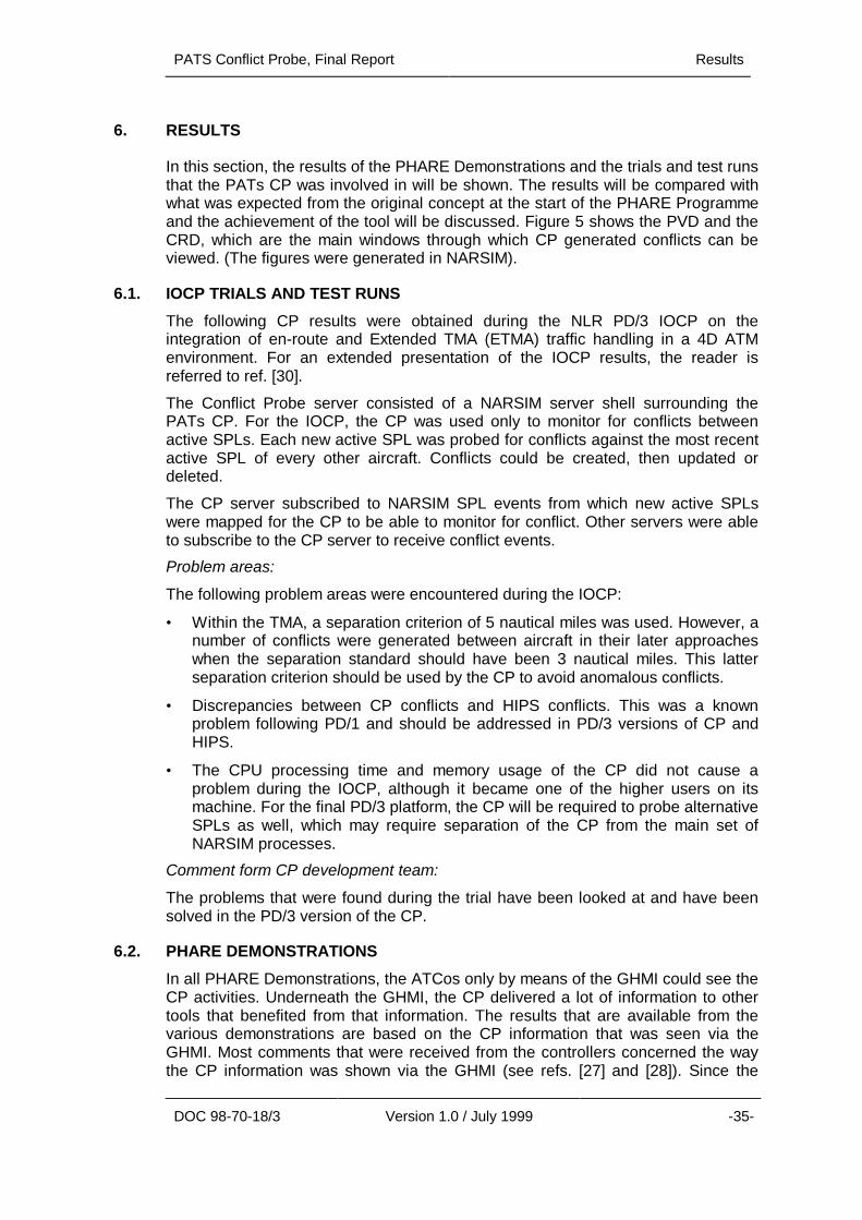
In this section, the results of the PHARE Demonstrations and the trials and test runsthat the PATs CP was involved in will be shown. The results will be compared withwhat was expected from the original concept at the start of the PHARE Programmeand the achievement of the tool will be discussed. Figure 5 shows the PVD and theCRD, which are the main windows through which CP generated conflicts can beviewed. (The figures were generated in NARSIM).
6.1. IOCP TRIALS AND TEST RUNS
The following CP results were obtained during the NLR PD/3 IOCP on theintegration of en-route and Extended TMA (ETMA) traffic handling in a 4D ATMenvironment. For an extended presentation of the IOCP results, the reader isreferred to ref. [30].
The Conflict Probe server consisted of a NARSIM server shell surrounding thePATs CP. For the IOCP, the CP was used only to monitor for conflicts betweenactive SPLs. Each new active SPL was probed for conflicts against the most recentactive SPL of every other aircraft. Conflicts could be created, then updated ordeleted.
The CP server subscribed to NARSIM SPL events from which new active SPLswere mapped for the CP to be able to monitor for conflict. Other servers were ableto subscribe to the CP server to receive conflict events.
Problem areas:
The following problem areas were encountered during the IOCP:
• Within the TMA, a separation criterion of 5 nautical miles was used. However, anumber of conflicts were generated between aircraft in their later approacheswhen the separation standard should have been 3 nautical miles. This latterseparation criterion should be used by the CP to avoid anomalous conflicts.
• Discrepancies between CP conflicts and HIPS conflicts. This was a knownproblem following PD/1 and should be addressed in PD/3 versions of CP andHIPS.
• The CPU processing time and memory usage of the CP did not cause aproblem during the IOCP, although it became one of the higher users on itsmachine. For the final PD/3 platform, the CP will be required to probe alternativeSPLs as well, which may require separation of the CP from the main set ofNARSIM processes.
Comment form CP development team:
The problems that were found during the trial have been looked at and have beensolved in the PD/3 version of the CP.
6.2. PHARE DEMONSTRATIONS
In all PHARE Demonstrations, the ATCos only by means of the GHMI could see theCP activities. Underneath the GHMI, the CP delivered a lot of information to othertools that benefited from that information. The results that are available from thevarious demonstrations are based on the CP information that was seen via theGHMI. Most comments that were received from the controllers concerned the waythe CP information was shown via the GHMI (see refs. [27] and [28]). Since the
Results PATS Conflict Probe, Final Report
-36- Version 1.0 / July 1999 DOC 98-70-18/3
GHMI project was a different project than the PATs project, results will be givenvery briefly.
In PD/1, the conflict information generated by the CP could be seen in the ConflictRisk Display and the controller could zoom into the situation where closestapproach was expected, by using the CZW. The general controllers view was thatsince the HIPS was used to show and solve conflicts, there was no more need for aCRD or CZW. It was thought that the CRD and CZW could be replaced by a list ofconflicts.
In PD/2, the majority of the controllers agreed with the support given to detectconflicts. They disagreed with the support given to solve these conflicts. In PD/2there was no HIPS available to solve conflicts. The CRD was the main supplier ofconflict information to the controller. Overall, there were no significant positiveresponses given at all on the CRD. As mentioned earlier, this indicated someshortcomings of the CRD, which were extensively commented by the controllers. Intotal, controller approval was significantly negative regarding the frequent use of theCRD and its relevance for controller work. The automatic pop-up of the CRD on allPVDs at the same time was severely criticised, mainly because controllers oftenfound the CRD displayed conflicts that were not relevant in their sector. It wasobserved during the simulations that controllers frequently closed the CRD windowimmediately after it was displayed. Presumably, there would have been moreacceptance of the CRD if, as controllers suggested, it had been modified so that itonly appeared on the display of the sector concerned. The assessment of the CRDshelpfulness for avoiding conflicts showed no clear indication of approval ordisapproval. The criticism here was that "… it is useful to detect the conflict but notto solve it ...". Tactical controllers would have appreciated some advisories to solveconflicts. No clear indications were found in their judgements about the CRDsusefulness for reducing their workload.
In PD/3, the main comment of the controllers with respect to conflict detection andresolution is that when a conflict has been solved by means of the HIPS, it turnedout that the CRD still displayed this (solved) situation as a conflict. The reason forthis is already explained in this report: HIPS and CP use different, inconsistentconflict detection functions.
A number of findings of controllers that have participated in PD/1++, show that theCRD tool (using conflict information from the CP) would appear to be a tool of highreliability, and utilisation. These findings are quoted from ref. [32].
• “… of all the tools that I could pay least attention to before this simulation, andthe one that I came to trust most during the simulation, was the Conflict Riskdisplay. It actually didn’t let me down when everything else did, most of thetime”.
• “It’s the only thing you’ve got to remind you of outstanding problems you haven’tsolved. If you’re a planner, if you didn’t have the CRD, you would really have toresolve everything at the time that it was offered to you because otherwiseyou’ve got no way of remembering what your outstanding tasks are”.
• ‘I found myself looking at it (CRD) quite a lot to see what was going on”;

PATS Conflict Probe, Final Report Results
DOC 98-70-18/3 Version 1.0 / July 1999 -37-
• “The nice thing about the CRD is you can set it to 25 minutes or 15 minutes orwhatever you want. You can do your essential entry tasks to make sure theaeroplane comes in safely and you know that sooner or later that little red signis going to come rolling in on the right to remind you, if you have forgotten it, thatthere’s still a separation task you’ve got to resolve. It’s excellent for that, it’s theonly aide memoir that you’ve actually got on the whole system. Everything elseis ‘do it’ ‘done it’ – that’s the one thing that reminds you of outstanding tasks,and it also tends to be very reliable and accurate”
Another result from PD/1++ (also quoted from ref. [32]) with respect to conflictdetection is that the CRD presented some conflicts that were not presented withinthe HIPS tools. There seemed to be several occasions when the HIPS and CRDtools were not in agreement. Generally though the controllers felt the CRD was themore accurate tool for determining conflicts.
6.3. ACHIEVEMENT OF CONCEPT
There are four major operational concepts described in section 2.1.2. In thissection, it will be explained which of the operational concepts have been fullyachieved and which of the operational concepts have not been fully achieved. Thereasons why an operational concept has not been fully achieved will be given.
6.3.1. Areas achievedDuring the three demonstrations PD/1, PD/2 and PD/3, the CP made use of variouskey operational concepts: protection zone SPL conflict probing, nominal path SPLconflict probing, and area conflict probing (see section 2.1.2). The output of the CPwas shown through the CRD. There were comments on the way the CRD was to beused. However, the output of the CP was not questioned. Therefore, the concept asin the context of conflict detection was fully achieved. This includes nominal pathSPL conflict probing and protection zone SPL conflict probing. Also theincorporation of wake vortex conflicts has been achieved. Finally, the support of theCP to other PATs has been achieved. It was possible for all other PATs to use theconflict information that was generated by the CP. For example, the concept ofchecking "what-if" trajectories for conflicts (e.g. by the Arrival Manager) has beenperformed well. The support of the CP to the HIPS has not been fully achieved,which will be explained in the next section.
6.3.2. Areas not fully achievedThe HIPS used an internal SPL conflict probing mechanism instead of conflictinformation from the CP (the conflict detection had to be very fast, which could notbe done through a connection between the HIPS and the CP). This introduced thepossibility of inconsistencies in the system. This would have been avoided when theHIPS would also have used the CP for internal SPL conflict probing.
The next area not fully achieved during the PATs project is the probabilistic SPLconflict probing approach. Since it was decided not to use the probabilistic algorithmfor conflict detection, this concept has not fully been achieved. The reason for notusing this approach for conflict detection was that probabilistic conflict informationcould not be handled functionally within the system.
Another functionality of the CP was to detect aircraft that were expected to fly inrestricted areas. Technically it was possible for other entities to subscribe to eventsthat signalled restricted area infringements. However, since no restricted area hasbeen defined in the system, no entity made use of this subscription mechanism. Sothis concept has not fully been achieved.
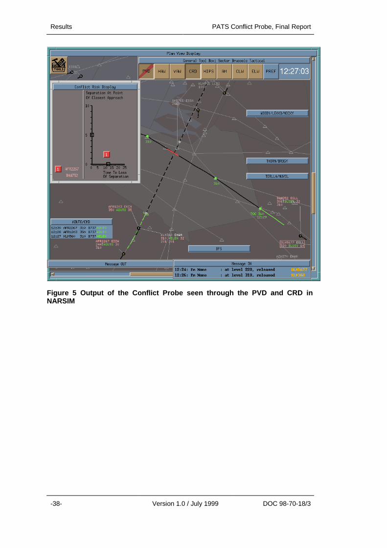
Results PATS Conflict Probe, Final Report
-38- Version 1.0 / July 1999 DOC 98-70-18/3
Figure 5 Output of the Conflict Probe seen through the PVD and CRD inNARSIM
PATS Conflict Probe, Final Report Conclusion and Recommendations
DOC 98-70-18/3 Version 1.0 / July 1999 -39-
7. CONCLUSION AND RECOMMENDATIONS
In this section the main issues from the previous sections will be summarized andconclusions will be given. Finally, recommendations for further research will begiven.
7.1. CONCLUSION
The development of the Conflict Probe was by means of a stepwise progressionthrough a series of PDs. PD/1 took place in late 1995; PD/2 took place in June 1996and PD/3 took place in 1998.
PD/1 was based on an en-route scenario hosted by NATS. An initial version of theCP was developed and integrated with other tools within the CMS framework. Thescope of the tool was to detect conflicts in the en-route sector. This version of theCP was based on protection zone SPL conflict probing. The existing NLR ACODalgorithms were the basis for this version of the CP.
PD/2 was based on a TMA scenario hosted by DLR. A nominal path SPL conflictprobing algorithm that could handle the more dynamic nature of air traffic in theTMA replaced the algorithm of the PD/1 version of the CP. Also, TMA specific SPLconflict probing difficulties, such as wake vortex conflicts and conflicts on theground were handled by the PD/2 version of the CP.
PD/3 was based on a multi-sector scenario hosted by NLR, EEC and CENA. Thisscenario included the full route of aircraft from take off to touch down. Additional tothe existing PD/2 version of the CP, area conflict probing algorithms wereincorporated in the PD/3 version of the CP.
In all the PHARE Demonstrations and IOCPs, the CP activities could only be seenby means of the GHMI. Underneath the GHMI, the CP delivered a lot of conflictinformation to other tools that benefited from that information. The results that areavailable from the various demonstrations are based on the CP information thatwas seen through GHMI. Most comments that are collected from the controllersconcern the way the CP information is shown through GHMI.
In all PHARE Demonstrations, PD/1 to PD/3, the CP has had an important functionwithout which the system would not have been complete. The latest version of theCP has been integrated on three platforms: NARSIM at NLR, ESCAPE at EEC andDAARWIN at CENA. Also, a stand-alone version of the CP has been developed sothat stand-alone tests can be done.
The development of the CP was aimed at providing
• a tool box function in composition with other PATs,
• a research tool in the area of conflict probing,
• a tool that can be easily adapted to meet new (research) requirements,
• a tool that can be easily integrated in several ATC environments.
The above goals were set before the development of the CP. The first goal, todevelop a tool box function in composition with other PATs, has been partlyreached. Some interactions with other PATs are not satisfactory, because thepossibility of conflict inconsistencies still exist in the PATs cluster (CP, CT, HIPS).The second goal, to develop a research tool in the area of conflict probing, hasbeen reached. The CP software can easily be adapted to any environment and new
Conclusion and Recommendations PATS Conflict Probe, Final Report
-40- Version 1.0 / July 1999 DOC 98-70-18/3
algorithms can easily replace existing algorithms. The last two goals have also beenreached.
With respect to the development path of the CP, the following can be concluded.The purpose of the PATs project was that the tools would be developed in thesimulation environment CMS. If all tools had been integrated on the samesimulation platform, test runs could have been made and the PATs cluster couldhave been evaluated and validated. However, the development of CMS wasplanned parallel to the development of the tools. The result of this parallel approachwas that a lot of time was needed for the tool developers to integrate the tools insuccessive CMS versions. A lesson learnt is that the development of the simulationenvironment, in which ATC tools can be evaluated and validated, should be donebefore the development of the tools themselves start.
It turned out that the approach followed by the PATs project was a tool drivenapproach rather than a concept driven approach. With a tool driven approach, thetools are developed almost independently of each other. Only after somedevelopment work was finished was it noticed that some tools had incorporatedconflicting functionalities or had overlap in functionalities. In general, the tools werenot optimal consistent with each other.
For a successful development of an ATC tools cluster, a concept driven approachwould have been better. All the tools should have been developed according tocommon concepts, which everybody had agreed upon, and the various activitiesshould have been geared to one another to a much greater extent than was donewithin this project.
7.2. RECOMMENDATIONS
The PHARE project has generated a lot of information that can be used as input toother projects in the field of ATC. From the CP development, the following ideas arerecommended as a basis for further research.
To reduce the possibility of having inconsistencies in conflict reports from variousPATs, the CP development team had decided to perform SPL conflict probing usingthe nominal path SPL conflict probing approach. This approach is easy tounderstand and interpret so that other PATs that perform SPL conflict probing cantune their SPL conflict probing approach to minimise inconsistencies in the PATscluster.
The latest development in the SPL conflict probing area, the probabilistic approach,was not used to detect conflicts during the PHARE demonstrations. However,further research in the area of probabilistic SPL conflict probing is recommendedbecause it can provide information upon which the decision-making processes ofthe controllers can be improved. An important question that has to be answered inthis area is how the information that can be generated by the probabilistic SPLconflict probing approach should be presented to the controllers. This question isrecommended as a subject for further research as well. This research should bedone in co-operation with human factors experts.
PATS Conflict Probe, Final Report Main Abbreviations and Acronyms
DOC 98-70-18/3 Version 1.0 / July 1999 -41-
8. MAIN ABBREVIATIONS AND ACRONYMS
4D 4-Dimensional
ACOD Area Conflict Detection tool
AM Arrival Manager
AMD Arrival Management Display
ANSI American National Standardization Institute
API Application Programming Interface
ATC Air Traffic Control
ATCo Air Traffic Controller
ATM Air Traffic Management
CENA Centre d'Etudes de la Navigation Aérienne
CMS Common Modular Simulator
CP Conflict Probe
CRD Conflict Risk Display
CT Cooperative Tools
CZW Conflict Zoom Window
DAARWIN Distributed ATM Architecture based on RNAV WorkstationsIntelligent tools and Networks
DLR Deutsche Forschungsanstalt für Luft- und Raumfahrt
DM Departure Manager
DRA Defence Research Agency
EEC EUROCONTROL Experimental Centre
ESCAPE EUROCONTROL Simulation Capability And Platform forExperimentation
ETMA Extended Terminal Manoeuvring Area
ETO Estimated Time Over
EUROCONTROL European Organisation for the Safety of Air Navigation
FIR Flight Information Region
FPM Flight Path Monitor
FTE Fast Time Environment
GHMI Ground Human Machine Interface
HIPS Highly Interactive Problem Solver
HMI Human Machine Interface
IDD Interface Description Document
IOCP Internal Operational Clarification Project
ISO International Standardization Institute

Main Abbreviations and Acronyms PATS Conflict Probe, Final Report
-42- Version 1.0 / July 1999 DOC 98-70-18/3
LVB Luchtverkeersbegeleiding (Air Traffic Control, the Netherlands)
NARSIM NLR ATC Research Simulator
NATS National Air Traffic Services
NLR Nationaal Lucht- en Ruimtevaartlaboratorium
(National Aerospace laboratory, the Netherlands)
NM Negotiation Manager
PARADISE Prototype of an Adaptable and Reconfigurable ATMDemonstration and Integration Simulation Environment
PAT PHARE Advanced Tool
PC Personal Computer
PD PHARE Demonstration
PHARE Programme for Harmonised ATM Research in EUROCONTROL
PS Problem Solver
PVD Plan View Display
RLD Rijksluchtvaartdienst
SIGMET Significant Meteorological area
SPL System Plan
TMA Terminal Manoeuvring Area
TP Trajectory Predictor
TRA Temporarily Restricted Area
PATS Conflict Probe, Final Report References
DOC 98-70-18/3 Version 1.0 / July 1999 -43-
9. REFERENCES
[1] H.A.P. Blom, G. Dean, M. Le Guillou, E. Petre and U. Völckers, 'The PHAREAdvanced Tools', In Machine intelligence in Air Traffic Management, pp. 25/1-25/8, 1993, AGARD-Conference proceedings.
[2] Eurocontrol, 'PHARE Advanced Tools: PATs IDD – Interface Document',version 2.3, PATs/CET/GEN/IDD/2.3/94/312, September 1994.
[3] Eurocontrol, 'PHARE Advanced Tools Initial Requirements and PlanningDocument', version 1.1, July 1992.
[4] PHARE Cell, 'PHARE: Glossary of Terms and Acronyms', DOC 97-70-05,version 4, April 1997.
[5] I.A.B. Wilson, ‘PHARE: Definition and use of Tubes’, Version 1.1, PHAREDocument DOC 96-70-18, July 1996.
[6] I. Fairclough (NATS), ‘PHARE Advanced Tools Arrival Manager Final Report’,PHARE Document DOC 98-70-18 (Volume 2 of 10), 1998.
[7] B. Cazard, P.Q. Nguyen (CENA), ‘PHARE Advanced Tools Co-operative ToolsFinal Report’, PHARE Document DOC 98-70-18 (Volume 3 of 10), 1998.
[8] E. Dubouchet, G. Mavoian, E. Page (CENA), ‘PHARE Advanced ToolsDeparture Manager Final Report’, PHARE Document DOC 98-70-18 (Volume5 of 10), 1998.
[9] R.B.H.J. Jansen, H.J. Kremer and W.C. Vertegaal, ‘PHARE Advanced ToolsFlight Path Monitor Final Report’, PHARE Document DOC 98-70-18 (Volume 6of 10), 1998.
[10] I. Fairclough, S. Flann (NATS), ‘PHARE Advanced Tools Negotiation ManagerFinal Report’, PHARE Document DOC 98-70-18 (Volume 7 of 10), 1998.
[11] M. Whiteley (EEC), ‘PHARE Advanced Tools Problem Solver Final Report’,PHARE Document DOC 98-70-18 (Volume 8 of 10), 1998.
[12] M. Whiteley (EEC), ‘PHARE Advanced Tools Tactical Load Smoother FinalReport’, PHARE Document DOC 98-70-18 (Volume 9 of 10), 1998.
[13] I. Fairclough, D. McKeever (NATS), ‘PHARE Advanced Tools TrajectoryPredictor Final Report’, PHARE Document DOC 98-70-18 (Volume 10 of 10),1998.
[14] I.A.B. Wilson, ‘PHARE Advanced Tools Umbrella Document’, PHAREDocument DOC-98-70-18 (Volume 1 of 10), 1998.
[15] H.A.P. Blom and B.A. van Doorn, 'A Description of the PHARE AdvancedConflict Probing Tool', April 192, NLR CR 92277 L.
[16] NLR/EEC/CENA, 'PD/3 Operational Scenarios Document (Volume I)',PHARE/NLR/PD3-1.1.3.2.2/OSD1;2.2, January 1997.
[17] NLR/EEC/CENA, 'PD/3 Operational Scenarios Document (Volume II)',PHARE/NLR/PD3-1.1.3.2.2/OSD2;2.0, March 1997.
[18] Vink, C.J.M. de Jong, J.N.P. Beers, ‘Medium Term Conflict Detection’, AirTraffic Management R&D Seminar, Saclay-France, June 1997.
References PATS Conflict Probe, Final Report
-44- Version 1.0 / July 1999 DOC 98-70-18
[19] G.J. Bakker, H.A.P. Blom, ‘Air Traffic Collision Risk Modelling’, In Proceedingsof the 32nd IEEE Conf. on Decision and Control, pp. 1464-1469, December1993.
[20] H.J. Kremer, G.J. Bakker, ‘A Probabilistic Approach towards Conflict Probing’,NLR Report TR 97041 L, 1997.
[21] H.J. Kremer, G.J. Bakker and H.A.P. Blom, 'Probabilistic versus geometricconflict probing', presented at the 1st U.S.A./Europe Air Traffic ManagementR&D Seminar, Saclay France, June 1997.
[22] P.G. Reich, 'A theory of safe separation standards for Air Traffic Control',Technical report 64041, Royal Aircraft Estavlishment, U.K., 1964
[23] W.C. Vertegaal, H.H. Hesselink and B.A. van Doorn, 'Interface DescriptionDocument PHARE Advanced Conflict Probing Tool', Version 3.1, NLR reportCR-98530, November 1998.
[24] W.C. Vertegaal and H.H. Hesselink, 'Architectural Design Document PHAREAdvanced Conflict Probing Tool', Version 3.1, NLR report CR-98529,November 1998.
[25] E. Yourdon, 'Modern Structured Analysis', Prentice-Hall International Editions,Englewood Cliffs, N.J., 1989.
[26] H.J. Kremer, W.C. Vertegaal, 'User Requirements Document PHAREAdvanced Conflict Probing Tool', version 3.1 to appear in 1998.
[27] NATS Ltd, PD/1 Final Report, PHARE/NATS/PD1-10.2/SSR;1.1, DOC 96-70-24, January 1997.
[28] DLR, PD/2 Final Report, PHARE/DLR/PD/2-10.2/SSR;1.2, DOC 97-70-13,February 1998.
[29] W.C. Vertegaal, 'User Guide PHARE Advanced Conflict Probing Tool', version3.1 to appear in 1998.
[30] NLR, 'PD/3 IOCP Programme, En-route / Extended TMA Integration',PHARE/NLR/PD3-4.1.3.3.6/SSR;1.0, May 1997.
[31] F. Rainback, D. Hudson, A. Lucas, ‘PD/3 IOCP – NATS. PD/1+ Trial Report’,Draft Version, PD3/NATS/IOCP/RPT002/DR1, April 1997.
[32] NATS Trials Team, ‘PD/1++ Trial Report’, PHARE/NATS/PD1++-2.10, DOC-98-70-16, October, 1998.
[33] F. Rainback, M. Beauchamp, L. Clarke, D. Hudson, S. Guest, S. Russell, P.Whysall, ‘PD/2+ Trial Report’, Draft Version, PHARE/NATS/PD2+-5.10, DOC97-70-17, May 1998.