Embed Size (px)
Citation preview
SLC
Industrial Mini SATA III Module
PHANES-K Series
(JEDEC MO-300A)
Document No. : 100-xBMSM-PKCTC Version No. : 02V0 Date : May, 2019

Product Features
- 2 - APRO SLC Industrial Mini SATA III Module (mSATA) PHANES-K Series
Product Features Flash IC
- TOSHIBA NAND Flash IC.
- Single-Level Cell (SLC) management
Compatibility
- SATA Revision 3.2
- SATA 1.5Gb/s; SATA 3Gb/s & SATA 6Gb/s data
transfer rate.
- ATA-8 ACS4 command set
Additional Capabilities
- S.M.A.R.T.*1 (Self-Monitoring, Analysis and
Reporting Technology) feature set support.
- Thermal Monitor for SSD’s temperature.
- Native Command Queuing (NCQ) support.
- TRIM maintenance command support.
- Both Static & Dynamic wear-leveling algorithm
- Hardware Low Density Parity Check Code, LDPC
support.
Mechanical
- JEDEC MO-300A full size Solid State Drive
- 52 pos. Edge Connector, PCI Express (PCIe) mini
- Dimension: 50.8 mm x 29.85 mm.
- Weight: 8.00 g / 0.28 oz.
Power Operating Voltage +3.3V±5%
- Read Mode: 1,650.0 mW (max.)
- Write Mode: 1,730.0 mW (max.)
- Idle Mode: 325.0 mW (max.)
Performance (Maximum value) *2
- Sequential Read: 510.0 MB/sec. (max.)
- Sequential Write: 305.0 MB/sec. (max.)
Capacity
- 8GB, 16GB and 32GB.
Reliability
- TBW: Up to 325 TBW at 32GB Capacity.
(Client workload by JESD-219A)
- MTBF: > 3,000,000 hours.
- ECC: Designed with hardware LDPC ECC engine
with hard-decision and soft-decision decoding.
- Temperature: (Operating)
Standard Grade: 0ºC ~ +70ºC
Industrial Grade: -40ºC ~ +85ºC
- Vibration: 80 Hz to 2000 Hz, 20G, 3 axes.
- Shock: 0.5ms, 1500 G, 3 axes
Certifications and Declarations
- Certifications: CE & FCC
- Declarations: RoHS & REACH
Remarks:
1. Support official S.M.A.R.T. Utility.
2. Sequential performance is based on CrystalDiskMark
5.1.2 with file size 1000MB
Order Information
- 3 - APRO SLC Industrial Mini SATA III Module (mSATA) PHANES-K Series
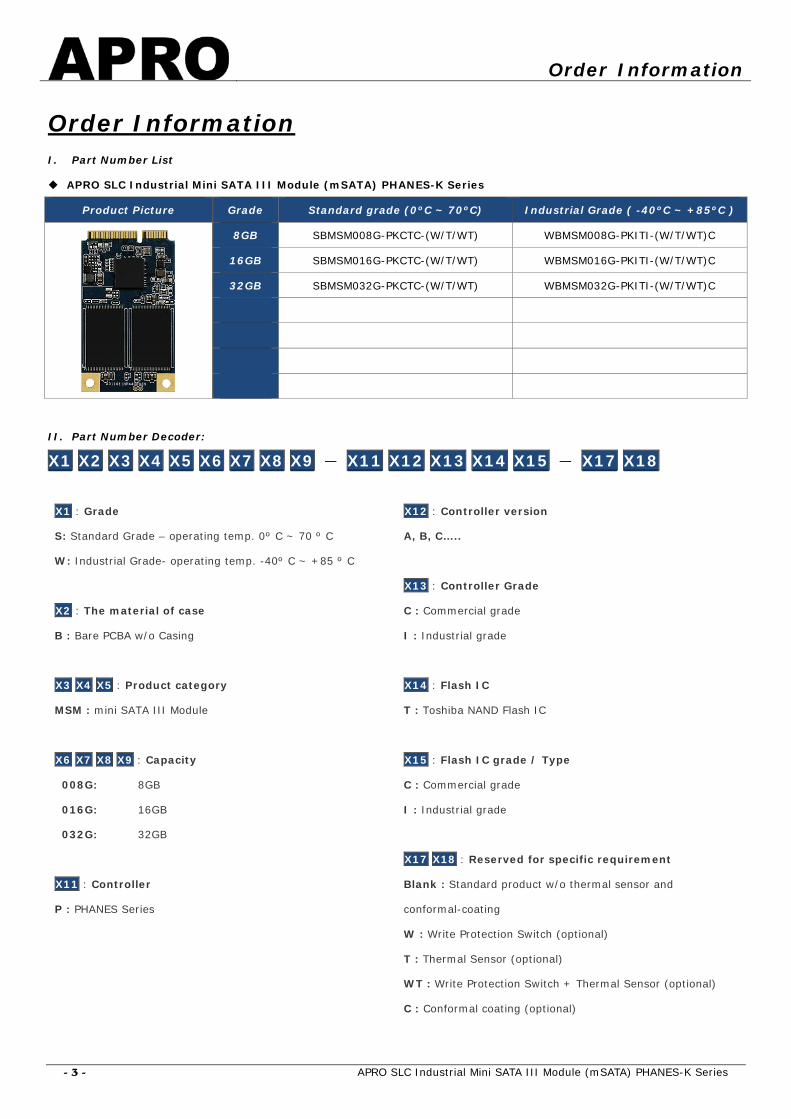
Order Information I. Part Number List
APRO SLC Industrial Mini SATA III Module (mSATA) PHANES-K Series
Product Picture Grade Standard grade (0ºC ~ 70ºC) Industrial Grade ( -40ºC ~ +85ºC )
8GB SBMSM008G-PKCTC-(W/T/WT) WBMSM008G-PKITI-(W/T/WT)C
16GB SBMSM016G-PKCTC-(W/T/WT) WBMSM016G-PKITI-(W/T/WT)C
32GB SBMSM032G-PKCTC-(W/T/WT) WBMSM032G-PKITI-(W/T/WT)C
II. Part Number Decoder:
X1 X2 X3 X4 X5 X6 X7 X8 X9 - X11 X12 X13 X14 X15 - X17 X18
X1 : Grade
S: Standard Grade – operating temp. 0º C ~ 70 º C
W: Industrial Grade- operating temp. -40º C ~ +85 º C
X2 : The material of case
B : Bare PCBA w/o Casing
X3 X4 X5 : Product category
MSM : mini SATA III Module
X6 X7 X8 X9 : Capacity
008G: 8GB
016G: 16GB
032G: 32GB
X11 : Controller
P : PHANES Series
X12 : Controller version
A, B, C…..
X13 : Controller Grade
C : Commercial grade
I : Industrial grade
X14 : Flash IC
T : Toshiba NAND Flash IC
X15 : Flash IC grade / Type
C : Commercial grade
I : Industrial grade
X17 X18 : Reserved for specific requirement
Blank : Standard product w/o thermal sensor and
conformal-coating
W : Write Protection Switch (optional)
T : Thermal Sensor (optional)
WT : Write Protection Switch + Thermal Sensor (optional)
C : Conformal coating (optional)

Revision History
- 4 - APRO SLC Industrial Mini SATA III Module (mSATA) PHANES-K Series
Revision History Revision Description Date
1.0 Initial release. 2018/11/08
1.1 Updated Version 2018/11/28
2.0 Updated document form 2019/05/21

Contents
- 5 - APRO SLC Industrial Mini SATA III Module (mSATA) PHANES-K Series
Contents Product Features ...................................................................................................................- 2 -
Order Information .................................................................................................................- 3 -
I. Part Number List ...................................................................................................- 3 -
II. Part Number Decoder: .......................................................................................- 3 -
Revision History ....................................................................................................................- 4 -
Contents ..............................................................................................................................- 5 -
1. Introduction .........................................................................................................- 6 -
1.1. Scope .............................................................................................................- 7 -
1.2. Flash Management Technology - Static & Dynamic Wear Leveling .................- 7 -
1.3. Bad Block Management ..................................................................................- 7 -
1.4. Mean Time Between Failure (MTBF) ...............................................................- 7 -
1.4.1. Definition ....................................................................................................- 7 -
1.4.2. Obtaining MTBF ...........................................................................................- 8 -
1.4.3. Definitions ..................................................................................................- 9 -
2. Product Specifications ........................................................................................ - 11 -
2.1. System Environmental Specifications ........................................................... - 11 -
2.2. System Power Requirements ....................................................................... - 11 -
2.3. System Performance .................................................................................... - 11 -
2.4. System Reliability ........................................................................................ - 12 -
2.5. Physical Specifications ................................................................................. - 12 -
2.6. Conformal coating ........................................................................................ - 13 -
3. Interface Description .......................................................................................... - 14 -
3.1. SLC Industrial Mini SATA III Module (mSATA) interface .............................. - 14 -
3.2. Pin Assignments ........................................................................................... - 15 -
Appendix A: Limited Warranty ......................................................................................... - 16 -
Product Specifications
- 6 - APRO SLC Industrial Mini SATA III Module (mSATA) PHANES-K Series
1. Introduction APRO SLC Industrial Mini SATA III Module (mSATA) PHANES-K Series provides high capacity flash memory Solid State Drive (SSD)
that electrically complies with SATA Revision 3.2 standard. APRO SLC Industrial Mini SATA III Module (mSATA) PHANES-K Series
support SATA 1.5Gb/s; SATA 3Gb/s & SATA 6Gb/s data transfer rate with high performance. It is designed with mSATA form factor
by JEDEC MO-300A standard, and the available disk capacities are 8GB, 16GB and 32GB. The operating temperature grade is
optional for Standard grade 0°C ~ 70°C and Industrial Grade with conformal coating supports -40°C ~ +85°C.
APRO SLC Industrial Mini SATA III Module (mSATA) PHANES-K Series provide the high random speed for heavy-loading embedded
or server operations with space constraints for host computing systems; the performance of sequential read is up to 510.0 MB/sec.,
and sequential write is up to 305.0 MB/sec.
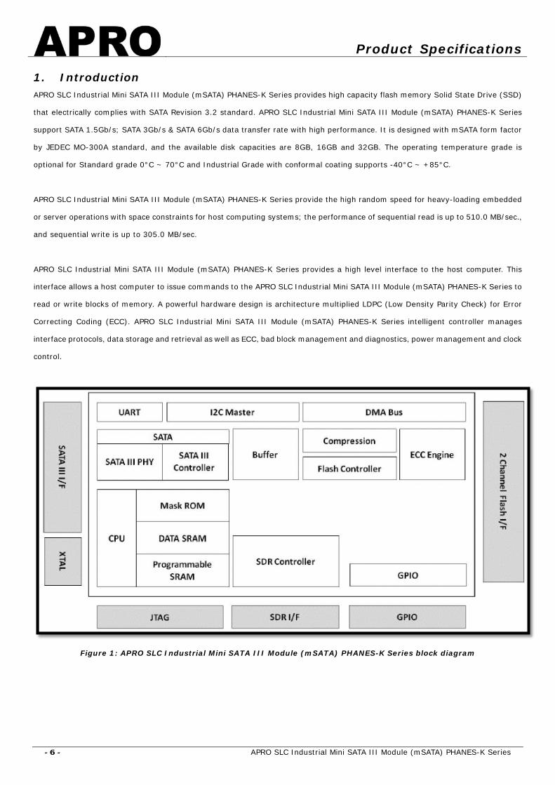
APRO SLC Industrial Mini SATA III Module (mSATA) PHANES-K Series provides a high level interface to the host computer. This
interface allows a host computer to issue commands to the APRO SLC Industrial Mini SATA III Module (mSATA) PHANES-K Series to
read or write blocks of memory. A powerful hardware design is architecture multiplied LDPC (Low Density Parity Check) for Error
Correcting Coding (ECC). APRO SLC Industrial Mini SATA III Module (mSATA) PHANES-K Series intelligent controller manages
interface protocols, data storage and retrieval as well as ECC, bad block management and diagnostics, power management and clock
control.
Figure 1: APRO SLC Industrial Mini SATA III Module (mSATA) PHANES-K Series block diagram

Product Specifications
- 7 - APRO SLC Industrial Mini SATA III Module (mSATA) PHANES-K Series
1.1. Scope This document describes features, specifications and installation guide of APRO SLC Industrial Mini SATA III Module (mSATA)
PHANES-K Series. In the appendix, there provides order information, warranty policy, RMA/DOA procedure for the most convenient
reference.
1.2. Flash Management Technology - Static & Dynamic Wear Leveling NAND flash devices can only undergo a limited number of program/erase cycles, and in most cases, the flash media are not used
evenly. If some areas get updated more frequently than others, the lifetime of the device would be reduced significantly. Thus, Wear
Leveling is applied to extend the lifespan of NAND Flash by evenly distributing write and erase cycles across the media.
APRO SLC Industrial Mini SATA III Module (mSATA) PHANES-K Series provides advanced Wear Leveling algorithm, which can
efficiently spread out the flash usage through the whole flash media area. Moreover, by implementing both dynamic and static Wear
Leveling algorithms, the life expectancy of the NAND flash is greatly improved.
1.3. Bad Block Management
Early Bad Block
The fault block generated during the manufacturing process of NAND Flash is called Early Bad Block.
Later Bad Block
In the process of use, as the number of operations of writing and erasing increases, a fault block is gradually generated, which is
called a Latter Bad Block.
Bad block management is a management mechanism for a bad block to be detected by the control IC and mark bad blocks in the
NAND Flash and improve the reliability of data access. The bad block management mechanism of the control IC will establish a Bad
Block Table when the NAND Flash is started for the first time, and will also record the errors found in the process of use in the bad
block table, and data is ported to new valid blocks to avoid data loss.
In order to detect the initial bad blocks to handle run time bad blocks, APRO SLC Industrial Mini SATA III Module (mSATA) PHANES-K
Series provides the Bad Block Management scheme. It remaps a bad block to one of the reserved blocks so that the data
contained in one bad block is not lost and new data writes on a bad block is avoided.
1.4. Mean Time Between Failure (MTBF)
1.4.1. Definition MTBF (Mean time between failures) is defined as failure or maintenance required for the average time including failure detection and
maintenance for the device. For a simple and maintainable unit, MTBF = MTTF + MTTR.
MTTF (mean time to failure) is defined as the expectation of random variables for time to failure.
MTTR(mean time to restoration) is the expectation of random variables of time required for restoration which includes the time
required for confirmation that a failure occurred, as well as the time required for maintenance.
Product Specifications
- 8 - APRO SLC Industrial Mini SATA III Module (mSATA) PHANES-K Series
1.4.2. Obtaining MTBF There are two methods for obtaining MTBF:
A. MTBF software estimation method: by calculating all the MTBF data of all the components included in the bill of material, and
the data of the completed products including actual parameters of voltage and electrical current using analysis software, the MTBF
of the completed product is estimated.
B. MTBF sample test method: by determining a certain number of samples and a fixed time for testing, using a Arrhenius Model
and Coffin-Manson Model to obtain parameters, and then using the formula with the parameters, the longevity and in so the
reliability is proved.
Arrhenius Model: Af = e{ (1/k × Ea ( 1/273+Tmax – 1/273+Ttest)}
Coffin-Manson Model: Af = ( ΔTtest/ΔTuse)m
APRO uses the A method to Estimate MTBF
MTBF is actually obtained by calculation which is just an estimation of future occurrences. The main reason to use the first method
is that the data contains the analysis by all the parameters of components and actual parameters of voltage and electrical current
of finished products, which is considered adequate and objective.
Interpretation of MTBF Analysis
APRO estimates MTBF using a prediction methodology based on reliability data for the individual components in APRO products. The
predicted MTBF based on Parts stress analysis Method of Telcordia Special Report SR-332, for components failure rates. Component
data comes from several sources: device life tests, failure analysis of earlier equipment, device physics, and field returns.
The Telcordia model is based on the Telcordia document, Reliability Prediction Procedure for Electronic Equipment, Technical
Reference SR-332. This standard basically modified the component models in MIL-HDBK-217 to better reflect the failure rates that
AT&T Bell Lab equipment was experiencing in the field and was originally developed by AT&T Bell Lab as the Bellcore model.
This model supports different failure rate calculation methods in order to support the taking into account of stress, burn-in,
laboratory, or field data. A Parts Count or Parts Stress analysis is included in Telcordia performance. Relex supports Telcordia Issues
1 and 2 and also Bellcore Issues 4, 5, and 6.Telcordia Issue 2, released in September 2006, are supported by Relex and Telcordia
Issue 1, released in May 2001, is replaced with Relex. Refer to Telcordia Issue 2 Fields for information about the fields in Relex
Reliability Studio specific to Telcordia Issue 2.
Purpose of the analyses
The purpose of these analyses is to obtain early estimation of device reliability during engineering and customer validation stages.
The prediction results will expose the reliability of whole assembly, viewed as a set of serially connected electronic components.
Rating of the assembly electronic components will show the ratio between actual critical elements parameters and their specification
limits. The purpose of component rating is to improve a product’s inherent design reliability, increase its number of operating times,
and to reduce warranty costs and to achieve a more robust design.

Product Specifications
- 9 - APRO SLC Industrial Mini SATA III Module (mSATA) PHANES-K Series
1.4.3. Definitions Term Definition
Failure The event, or inoperable state, in which any item or part of an item does not, or would not,
perform as previously specified.
Failure rate The total number of failures within an item population, divided by the total number of life units
expended by that population, during a particular measurement interval under stated condition.
FIT Failures In Time: the number of failures in 1 billion hours.
PPM Part per million: the number of failures in 1 million hours.
Mean Time Between Failures
(MTBF)
A basic measure of reliability for repairable items: The mean number of life units during which
all parts of the item perform within their specified limits, during a particular measurement
interval under stated conditions..
GB
Ground, Fixed, Controlled: Nearly zero environmental stress with optimum engineering
operation and maintenance. Typical applications are central office, environmentally controlled
vaults, environmentally controlled remote shelters, and environmentally controlled customer
premise area.
GF
Ground, Fixed, Uncontrolled: Some environmental stress with limited maintenance. Typical
applications are manholes, poles, remote terminals, and customer premise areas subject to
shock, vibration, temperature, or atmospheric variations.
Software & Database
Analysis Software & Analysis Method
Software Name:Relex Reliability Studio 2008
Software Version:Relex Studio 2008
Analysis Method
The prediction method used was Telcordia SR-332, Issue 2,
Parts Count
Failure rate (λ) = 109 hours (FITs)
MTBF=1/λ
λSSi = λGi TTQiTTSiTTTi
Where λGi:Generic steady-state failure rate for device i
TTQi:Quality factor for device i
TTSi:Stress factor for device i
TTTi:Temperature factor for device i
Calculation Parameter
Operation Temperature:25℃
Environment:Ground Benign, Controlled
Operation Stress:50% (Voltage, Current, Power)
Method:Method I, Case 3
Product Specifications
- 10 - APRO SLC Industrial Mini SATA III Module (mSATA) PHANES-K Series
Products are advertised with MTBF up to 1 million hours in the market. Take one million hours as an example, the product’s
estimated life is 114 years. However, the current rapid progress of technology, advancement of flash storage device's manufacturing
process research and development, and the supply period of former flash IC manufacturing processes are crucial to the actual life
expectancy of flash products. In short, the MTBF of flash storage is for reference only. Good customer service and technical support
provided by manufacturers is the most significant issue regarding to the life-span of products.
Remark:
All the details of testing and data are for reference only and do not imply any products performance as a result. MTBF is only an
estimated date and is depends on both hardware and software. User shall not assume that all the products have the same MTBF as
APRO estimates.

Product Specifications
- 11 - APRO SLC Industrial Mini SATA III Module (mSATA) PHANES-K Series
2. Product Specifications For all the following specifications, values are defined at ambient temperature and nominal supply voltage unless otherwise stated.
2.1. System Environmental Specifications
Table 1: Environmental Specification
APRO SLC Industrial Mini SATA III Module (mSATA)
PHANES-K Series
Standard Grade Industrial Grade
SBMSMxxxG-PKCTC WBMSMxxxG-PKITI
Temperature Operating:
Non-operating:
0ºC ~ +70ºC
-20ºC ~ +80ºC
-40ºC ~ +85ºC
-50ºC ~ +95ºC
Humidity Operating & Non-operating: 10% ~ 95% non-condensing
Vibration Frequency/Acceleration: 80 Hz to 2K Hz, 20G, 3 axes
Shock Operating & Non-operating: 0.5ms, 1500 G, 3 axes
Electrostatic
Discharge (ESD)
Temperature: 24ºC
Relative Humidity: 49% (RH)
+/-4KV: Device functions are affected, but EUT will be back to its normal or
operational state automatically.
2.2. System Power Requirements Table 2: Power Requirement
APRO SLC Industrial Mini SATA III Module (mSATA) PHANES-K Series
DC Input Voltage (VCC) +3.3V±5%
Maximum average value
Reading Mode : 1,650.0 mW (max.)
Writing Mode : 1,730.0 mW (max.)
Idle Mode : 325.0 mW (max.)
2.3. System Performance Table 3: System Performances
Data Transfer Mode supporting Serial ATA Gen-III (6.0Gb/s = 768MB/s)
Maximum
Performance
Capacity 8GB 16GB 32GB
Sequential Read (MB/s) 320.0 540.0 510.0
Sequential Write (MB/s) 70.0 150.0 305.0
Note:
The performance was measured using CrystalDiskMark v5.0x64 with SATA 6Gbps host.
Samples were built using Toshiba 15nm Toggle SLC NAND.
Performance may differ according to flash configuration, SDR configuration, and platform.
The table above is for reference only. The criteria for MP (mass production) and for accepting goods shall be discussed
based on different flash configuration.
Product Specifications
- 12 - APRO SLC Industrial Mini SATA III Module (mSATA) PHANES-K Series
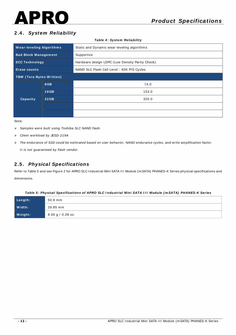
2.4. System Reliability Table 4: System Reliability
Wear-leveling Algorithms Static and Dynamic wear-leveling algorithms
Bad Block Management Supportive
ECC Technology Hardware design LDPC (Low Density Parity Check)
Erase counts NAND SLC Flash Cell Level : 60K P/E Cycles
TBW (Tera Bytes Written)
Capacity
8GB 74.0
16GB 153.0
32GB 325.0
Note:
Samples were built using Toshiba SLC NAND flash.
Client workload by JESD-219A
The endurance of SSD could be estimated based on user behavior, NAND endurance cycles, and write amplification factor.
It is not guaranteed by flash vendor.
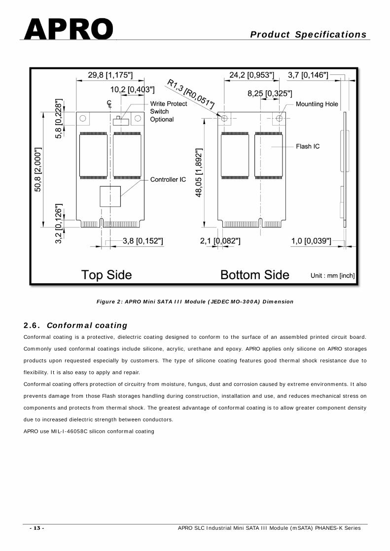
2.5. Physical Specifications Refer to Table 5 and see Figure 2 for APRO SLC Industrial Mini SATA III Module (mSATA) PHANES-K Series physical specifications and
dimensions.
Table 5: Physical Specifications of APRO SLC Industrial Mini SATA III Module (mSATA) PHANES-K Series
Length: 50.8 mm
Width: 29.85 mm
Weight: 8.00 g / 0.28 oz.
Product Specifications
- 13 - APRO SLC Industrial Mini SATA III Module (mSATA) PHANES-K Series
Figure 2: APRO Mini SATA III Module (JEDEC MO-300A) Dimension
2.6. Conformal coating Conformal coating is a protective, dielectric coating designed to conform to the surface of an assembled printed circuit board.
Commonly used conformal coatings include silicone, acrylic, urethane and epoxy. APRO applies only silicone on APRO storages
products upon requested especially by customers. The type of silicone coating features good thermal shock resistance due to
flexibility. It is also easy to apply and repair.
Conformal coating offers protection of circuitry from moisture, fungus, dust and corrosion caused by extreme environments. It also
prevents damage from those Flash storages handling during construction, installation and use, and reduces mechanical stress on
components and protects from thermal shock. The greatest advantage of conformal coating is to allow greater component density
due to increased dielectric strength between conductors.
APRO use MIL-I-46058C silicon conformal coating

Product Specifications
- 14 - APRO SLC Industrial Mini SATA III Module (mSATA) PHANES-K Series
3. Interface Description 3.1. Mini SATA III Module (mSATA) interface
Figure 3: The connectors of Signal Segment and Power Segment

Product Specifications
- 15 - APRO SLC Industrial Mini SATA III Module (mSATA) PHANES-K Series
3.2. Pin Assignments APRO SLC Industrial Mini SATA III Module (mSATA) PHANES-K Series operates with standard SATA pin-out. The pin assignments are
listed in below table 6.
Table 6 - Pin Assignments
Signal Name Pin # Pin # Signal Name
NC 1 2 +3.3V
NC 3 4 DGND
NC 5 6 NC
NC 7 8 NC
DGND 9 10 NC
NC 11 12 NC
NC 13 14 NC
DGND 15 16 NC
NC 17 18 DGND
NC 19 20 NC
SATA GND 21 22 NC
TX+ 23 24 +3.3V
TX- 25 26 SATA GND
SATA GND 27 28 NC
SATA GND 29 30 NC
RX- 31 32 NC
RX+ 33 34 DGND
SATA GND 35 36 NC
SATA GND 37 38 NC
+3.3V 39 40 DGND
+3.3V 41 42 NC
NC 43 44 DEVSLP
NC 45 46 NC
NC 47 48 NC
DAS 49 50 DGND
GND 51 52 +3.3V
Appendix-A
- 16 - APRO SLC Industrial Mini SATA III Module (mSATA) PHANES-K Series
Appendix A: Limited Warranty
APRO warrants your SLC Industrial Mini SATA III Module (mSATA) PHANES-K Series against defects in material and workmanship for
the life of the drive. The warranty is void in the case of misuse, accident, alteration, improper installation, misapplication or the result
of unauthorized service or repair. The implied warranties of merchantability and fitness for a particular purpose, and all other
warranties, expressed or implied, except as set forth in this warranty, shall not apply to the products delivered. In no event shall
APRO be liable for any lost profits, lost savings or other incidental or consequential damages arising out of the use of, or inability to
use, this product.
BEFORE RETURNING PRODUCT, A RETURN MATERIAL AUTHORIZATION (RMA) MUST BE OBTAINED FROM APRO.
Product shall be returned to APRO with shipping prepaid. If the product fails to conform based on customers’ purchasing orders,
APRO will reimburse customers for the transportation charges incurred.
WARRANTY PERIOD:
SLC STD. Grade 3 years / Within 60K Erasing Counts
SLC IND. Grade 5 years / Within 60K Erasing Counts
This document is for information use only and is subject to change without prior notice. APRO Co., Ltd. assumes no
responsibility for any errors that may appear in this document, nor for incidental or consequential damages resulting from the
furnishing, performance or use of this material. No part of this document may be reproduced, transmitted, transcribed, stored in a
retrievable manner or translated into any language or computer language, in any form or by any means, electronic, mechanical,
magnetic, optical, chemical, manual or otherwise, without the prior written consent of an officer of APRO Co., Ltd.
All parts of the APRO documentation are protected by copyright law and all rights are reserved.
APRO and the APRO logo are registered trademarks of APRO Co., Ltd.
Product names mentioned herein are for identification purposes only and may be trademarks and/or registered trademarks of their
respective companies.
© 2018 APRO Corporation. All rights reserved