Embed Size (px)
Citation preview
V~MRANtTMREZPORT M66 3-1
?PEROW4ANCE2 ANALYSIS OF DANIS G
LATINCHERS FOR VEHICLZS ~
By "~ J~'
AMCMS S523. 11.43400. 01
DA Project No. 155 3150ID338 OI14 ft~
Distribution of this document is unlimited.
AUGUST 1965
PHADLPHIA, PIA.,
.. . .. ... � ....... ... . ..'.. ....
Al, Oil':.'
a c men 44 b6,- 4. ,
of too ac
MEMORANDUM REPORT M66 -5i
PERFORMANCE ANAI..YSIS OF DAVIS GUN
ILAUNCHERS FOR VEHICLES
By
SIDNEY GOLDSTEIN4
AMCMS r-523.11,43400.01
DA Project No. 1I5O3I1D3i8
Distribution of this document is uniimited.
Small Caliber Engineering Directorate
FRANKFORD ARSENALPhiladelphia, Pa. 19137
August 196S
FOREWORD
The work described in this r e port was perft rmed by the Frank-ford Arsenal, U. S. Army Munitions Command under AMCMS Code55Z3. 11. 43400. 01 DA Project Numbar 15531501D339. Acknowledge-ment is made to Mr. Walter Gadomaki for his contribution to the sectionon Gun Weight Determinations.
ii
AB~STRAC T
A set of irnter,ýoj balitilx eqiations ig ý,,Ierived fo r a r~t ~type of '-auri( her of tbe Davis Gun type in whicL two nniaoes are ejec teti
fromr a -omorn cantOn
Bavd on ball:.stc inalysisf of tte Dav'~s Ciun i.u .cr it %ppearmsfeasible that a higtý perfc~rrm n~k eypr Da-vis C'un launc her cudbe ef-fectively used frtom a vehiclec.
TA4I-Ei OF C(ONTENTS
FORE . . . .
ABSTRACT ,.
OBJECT.
S. . . . . ... ....... ........ ....
INTR)ODU)CTION
ASSUMPTIONS . . . . . . . . . . . . .. . . . . . . .
THEOk(Y.. .......... . ....................... 2
Derivation of uations . . . . . . .. . . . .
BALLISTIC DESIGN ................. ... ................ 12
TO DETERAM;NE CILARGE WE1.HTGT I
TO DETFRK4rNF CIIAMBEi• V.: .ME ." . ...
TO [FTEi•MINF 1 FA• |•; E'Siks
TO FIN)D TOTA &L I .UN .N ..T
1T0 DEETE hMINF GUN WEIG1 HT. ...... . ..
WEV;HT f F'TERMVINA!IOj)N ...........
DLSCUS$ION .. ... . . . . . .. . . . . . . . ..
CONC I.USI(ONS . . . . . .. . . . . . . . ,. .
k F , F' " E h E N ( . E . . . ....... . . . . . . . . . . . . .
AF'PENDIX A A Method oi Selecting Fiu•nrng hrt-,e"W).... .•. . ... ..............
TABLE OF CONTENTS (Cont'd)
Page
APPENDIX B - Propellant Constants . . . . . . . . . . 29
DISTRIBUTION . . . . . . . 0 t * * . * . . * . . 47
LIST OF ILLUSTRhATIONS
Figure Title
1 C/M vs Velocity . . . . . . . . . . ...... 30
2 Charge vs Velocity M/M' = 1 . . .. . . . . 31
3 Charge vs Velocity M/M' = 1/2 . ...... . 32
4 Charge vs Velocity M/M' = 1/3 . . . . . . . . . 33
5 Chamber Volume vs Velocity M/M' = 1 . . . . . 34
6 Chamber Volume vs Velocity M/M' = 1/2 ... 35
7 Chamber Volume vs Velocity M/M' = 1/3 .... 36
8 Peak Pressure vs Loading Density, . . . . . . . 37
9 Total Gun Length vs Velocity.-Bore Diameter =
100 mm - M/M' = 1. . .. . .. .. 38
10 Total Gun Length vs Velocity-Bore Diameter00 rnm - M/M' = 1/2. . • . . . • . a • . • a . 39
11 Total Gun Length vs Velocity-Bore Diameter =100 mm- M/M' = 1/3 . . . . . . . . ... . 40
1z Tctal Gun Length vs Velocity - Bore Diameter =IZ0 mn - M/M' = 1 .. . o . . . ... . . . 41
13 Total Gun Length vs Velocity - Bore Diameter =lZO m m- M/M' = 1/2l . . . . . . . . * 0 . . . 42
v
LIST OF ILLUSTRATIONS (Cont'd)
Figure Title Page
14 Total Gun Length vs Velocity - Bore Diameter -
1ZO mrn - M/M' = 1/3 .............. 43
15 Total Gun Length vs Velocity - Bore Diamet -
140 mrn- M/M' = . . . . o. . . . . . . ... 44
16 Total Gun Length vs Vel-,ccity - Bore Diameter -
140 mm- M/M' = 1/Z . . . . . .... 45
17 Total Gun Length vs Velocity - Bore Diameter =
140 mm - M/M' = 1/3... ........... 46
vi
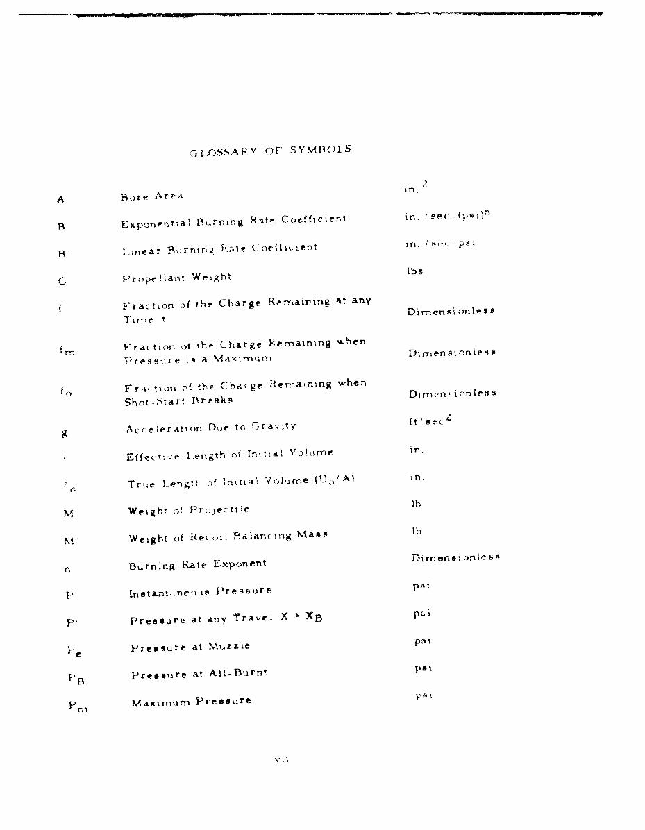
C.3IC),SSA,•V OF SYMBOLS
A Bore Area i
B Exponpntxal Buirning R3te Coefficient in, 'sec -(psC
B 1-;near B,_rniniz R.Iije coefficient In a uC -ps
C Proprilant Weight lbs
Fraction of the Charge Remainkins at any
Time DiTei lk onles s
f rT, Fraction of the Charge remaining when
Vress-6re is a Maximum Dirensionless
fo Fra, tion of the Chargre Ren-aning when
Shot-Start Breaihsm
g Ac eieration Due to Cravity tIseC
i Effe(.t-ve Length of Initial Voliume in.
Io Trkie Lengtt of Initial Vollure ( /A) in.
M Weight of ProJectiie lb
M Weight of Rec oil Balancing Mass lb
n Burning Rate Exponent Dimensioniess
I-) In tant.-.neois Pressure psi
Ij f Pressure at any Travel X " XB PC.I
Pe Pressure at Muzzle psi
H)B Pressure at All-Burnt psi
p Maximum Pressure psi
V6i
GLOSSARY (Cont'd)
PRs Pressure at which Shot-Start Breaks psi
Constant Temperature used to ObtainEffective Mean Impetus (A , nR*T) "K
To Isochorir Adiabatic Flame Temperature ,K
t Time sec
U 0 Initial Free Charnter Volume in.
U 0 Total Chariber Volume in.
U Volurne behind Pro.ectile at iny Time t in.
V Muzzle Velocity of Projectile ft!sec
W Propeliauit Web in.
X Projectile Travel at any Time in.
Xv Travel of Recoil Balmn' ing Mass rn.
X Travel at all-Burnt in.
"Xe Total Travel of the 1Projectile in.
""e Total Tra\ (e1 ot Re. oil Balancing Mast in.
""n-TITravel when IPreu~skre is a NlaximIun, In.
Y Ratio of Final Volunie to Initial Volume I ten 8 on ie S
YB Ratio of Final Voluwie to, Volumte at Al -
Burnt t. men s ion l e,
Y R atio of the Vohlimrt,, Behind the Promec -
tile at Any Travel X XB to the Volumebehind the Pro.e(tile at All-Bturnt Dt iens orlelf ,
I. I li
GLOSSARY (Cont d)
Heat Loss Coefficient Dimensionless
y' Ratio of Specific Heats Dimensionless
Effective Ratio of Specific Heats Dimensionless
6 Propellant Density lb/in. 3
SCo -V olum e in. 3 /lb
x Effective Mean Impetus ft-lb/lb
A Central Ballistic Parameter Dimensionless
a Propellant Form Factor Dimensionless
C4 M/M' + I Dimensionless
7k Xb/Xe Dimensionless
&o Loading Density grns 'cM 3
ix
OBJECT
To obtain a generalized set of interior ballistic equations for pre.-dicting the performance of Davit Gun launchers for vehicles. Considera-tion is given here to cases where the projectile weight is different fromthat of the recoiling mass. Also, the use of a shot-start device is takeninto account in the derivation of the equations.
SUMMARY
A set of interior ballistic equations is derived for a reactionlesstype of launcher of the Davis Gun ty-pe in which two masses are ejectedfrom a common charnbcr. The important interior ballistic equationsare summarized below. Travel and velocity are determined with refer-ence to the center of mass of the system.
VIeocity at all-burnt
AWgfoVB B 2B*M
Travel at all-burnt
r -, c. 4A 1 +x ( , I+ t fo0r ti 4 ,
B 0 fo i j(I-fo I for . 0XB - for- fC)
x,
Pressure at all.-burnt
12 CA for a 0
U", 4 Rfo
___B Iz Cx ____0
4f - I - fo
u e ( I - fo - o
T!e fraction of the web remaining at peak pressure
f for all 'd
The Travel at peak pressure
.• L- C fo~ +e÷"'
[ I ;o]II fo
x m• III f 0 j 11+ 5
Xm = tj[jE(j( .f 4' CI(I-fo) .. 1 for 0
Thepek res sure_
p12 C )A 1)fo ( 4 (b I
-- (1120) T
2 b + C41J
- (~sf~b I)2 for b 0
[ I+ O,, !"(f 0 +io)
'0 +
Xli
The muzzle velocity
xiii
INTRODUCTION
The purpose of this report is to develop the necessary interiorballistic equations for recoilless launching systems of the Davis Guntype for vehicles.
ASSUMPTIONS
1. In the derivation of the interior ballistic equations, use wasmade of the iscthermal model. I In this method, the temperature of thegases during the burning period was assumed to be a constant (T) whichwas taken at some mean value. The effective impetus X would then alsocorrespond to some mean value (i. e., X = nRT) during the burning period.
2. The direction of stroke is assumed horizontal so that no poten-tial energy is acquired by either body.
3. The volume (U) available to the gas behind the shot at any timeis U = Uo + OAX - Cf/6 - C(1 - f)77. Assuming that 77 = 1/5, this reducesto U = Uo + 02AX - C/6. When x 0 we define a quantity t. which may beinterpreted as the effective iength of the initial volume. t = Uo - C/6/AUo/A. Where Uo is the free volume behind the shot before it starts tomove.
4. The rate of burning is assumed to be proportional to the pres-sure; r = B'P (linear burning law, see Appendix A for a method of de-termining B' assuming the peak pressure is known).
5. There is no pressure gradient in the bore during the ballisticc yc le.
6. The effective ratio of specific heats remains constant,
NOTE: (7"- 1) = (I + 0)(Y- 1)
Where • - heat loss coefficient
y = true ratio of specific heats
1See References I and 2.
1
7, There is no motion of the shot until the siot-start pressure(that pressure at which the shear pins break) is reached.
Thus X > 0 only when P > Psv. The fraction of the web re-maining at the time the shot-start pressure is reached is denoted by fo.
8. The murnmentr•" •d !'A.E. of the prý,-ellant g asa ia aseumnedto be negligible.
THEORY
Derivation ofE uations
A. Basic Equations
I. Motcnztum Balance Equation
M' dV' M dVg dt -g dt
v,here M' is the weight of the recoiling or balancing mass and M i3 theweight of the projectile.
Assu:nilg that both masses begin to move at the same time
M' X' Z MX
or
MI
Thus
X, x÷] XW
The quantity
MM'
indenoted as Cl and thus
X 4 X' -Z iX.
2. Equation of State
PU 12) C (1 f) 'I + b )
or
p _1ZXC (I f) Aj 4 df (A •X 7 ) -Z
3. Equation of Motion
- AP (3)g dt
or
12M dV AP (3a)g dX
4. Equatxon of Web Regression
W dl _ B'P (4)dt
B. Procedure
Ehrmirnating P bez.ween the equation of web regression (4) andthe equation of motion (3)
M dV AW dfg dt ZB, dt
3
With the initial conditionz that V 0 0 when f -_ fo this equationintegrates to
V = AWg (f - 0) (9)ZB'M
or taking the derivative with respect to K
dV AW 1 df a)R BMB' dX
Starting with the equation of motion
1. ZM VdVSA P (1a)g dX
2 f 0 is a constant which represents the fraction of the web remaining
when the shot- - tart device breaks (i. e,, , at the time the shot begins tomove). The pressure at which this occurs is denoted by P5 6 and is de-termined by the material of the shot -start rod, its dimensions and therate of loading the system. The value of fo is obtained from the follow-ing equation (assuming P,, is known)
IZ CA, - fo) (I + Rf o )
P5 O
This equation may then be solved to determine fo
/ _ssk 5 12C)• (10 -ICA b - 2~
and
- fc, PO5 0
4
substitute (5) for V. (5a) for dV/'dX and for
L IZCk (I - f) I + OfAt.+ f! X)
and solve for
dX A 2 Wrg (Q X + t )(f 0 -f
dj7 4 (B) ?-MC), (I - f ) (I + 9 f
We now define a central ballistic parameter
4 (B' I M ck
Thu s
dX $A M - f )(l e
Integrating this equation with the initial conditions that at
X-- 0, f f 0 ; we get
C, (i- fo) U -~ ( o 0).*fO Le for"~ *r
and
IF, f(lf)X~Dsl-o f or (40 U)
Equation (6) gives us the travel in terme of the fraction of thieweb (f) rem-aining at any time t.
By substituting (6) into equation (2), it is now possible to de-termine the pressure (P) in terms of the fraction of the web (f) remainsat any time t.
p lzCx (1 - f) (I +Of) for 0
f__ -fo) + _0o
(,oiT':r(, o) i+ ,• (11 o- --
and
p lzCx (I f) for e = 0 (7)U.eAo A (-i ° -ff°l 'l; [ Clf°0]
It is now possible to determine the velocity, travel and pres-sure at all burnt (subscript B denotes the quantity when the propellantis all burnt, i.e., when f = 0) from equation (5) with f = 0.
VB= AWIgf (8)2BM
from equation (6) with f = 0
XB f ILIo) ;L,--•j(I + fo) 8 oL 1_ Jo f or 6 0(
XB= ? [er'fo(° - fo)Q•l[fo1] - for = O
6
PB 1 Afor b
U, (I - fo) f ,t]I f-)
And
PB A2C A , V 0
U -, eF.14 fo ( fo - (I -t°(10
To deterrmine , onditions at maximum pressure, the following
procedure will be used. Let the subscript n- denote the condition at
mraxIMum pressure.
From Equation (Z) we have pressure as functions of f and x,
P - P(f, x), and from Equation (6) we have x as a function f, x xUf
thus
dP (,11) F)) --- Qx 0 for niaximum I
x C Xb
( f UA(
We have atready shown that
dx C "x )(f - f)dt (1 . t•~ * f
Substituting into (iI) we get for f n the f(raction of the web
remaitnig at maxbnum preossre
fm = 1- for all 6 (,I Z)
To find ihe travel at mnaxirnum preasure we substitute fm
for f in equiatri (6) and get
Xm I !-fo)
l~El-
I .-( f°.o-jI f r• #
S-)(or no 0 (+ )
8 f1 T I JI8lo
0 c(CMf(9 -I) 4 (6 -I)A f
Ig, l + O f . . . - 9. . '
7/ 10 Tf 1'
+ | 278 ;+ C _
And
PM = zc for 8=0 (14),ý I o vo•( - fo) ) D• -f :3
Uoe ýFý(- - f,,) + I
It in imposit~ble: to have a solution with f n~egati~ve, at any timle.Thuo fjn mis~t always be positive 6.i,•,., Ogo 4. 0 -. I .)O otherwise
pekpressture cornea at all burnt and
Phi = pB - ,I- A for =0B oF fao] o}• l-fo-)
L
Note that in the case of a conventional gun without shot-start or recoil-ing parta and e 0
[• = lira + 1
t
fo =lim (I - Uo Psa/IZC)- 1
Pas -' o
12) CPB -,e U' es"
This agrees with equation (20A) P 138 of "Theory of the In-terior Ballistics of Guns" by Dr. J. Corner. 3 Our solution, however,ia much more general and is particularly applicable to systems usingthe Davis Gun principle.
To determine muzzle velocity, let subscript e denote condi-tion at muzzle exit. K. E. of projectile at muzzle exit = K. E. of pro-jectile at all-burnt 4 work done on the projectile from all burnt tomuzzle exit.
M V• f VP + Adx
2g B gB
See, Reference 2.
10
Let YB be the ratio of the volume behind the projectile at anytravel X > XB to the volume behindu the shot at the time of all-burnt.
,ý CX .B C •XB 4T
Using the adiabatic law for free expansion, we have the pressure (PI)at any travel X > XB given by
P P B (aXX'+ 'Y) PB (Yh)V
Using the fact that at X' IXB, YB and X - X Y Y
where YR is the ratio of the final volume to t'ie volume at all-burnt.
Xe
"A B
APB( XB + [t YB
and remembering that
PB A (P'X B A !):IZC
Ii2A
thus.
x1
72PdX W, _(16)IB
We have already s)hown in equation (8) that
A Wogf0VB -
thus•C~k• fo(17)
4(B,)ZM 0
Substituting equations (16) and (17) in equation (15) and solving for themuzzle velocity we get:
2• - _CI L f! Lti + j (18)
BAL LISTIC DESIGN
For purposes of establishing some preliminary design parameterssuch as charge weight, total gun length, peak pressure, and also g-.dn
weight for the Davis Gin the foiiow-ing design ballistic quantities wereselected as being typical of 'high performance guns.4
4 See References 3 and S.12
Expansion Ratio:- Final Volume (Y)Initial Volume
Travel of projectile to all-burntTotal rravel 0. 60
Loading Density (,60) 0 0. 70 grams/cm5 3
Propellant Constants See Appendix A & B
The range of projectile weights c )nsidered was from 3 to 12 lbs.and the weight of the recoiling mass was taken as 1, 2 and 3 tim-nes thatof the projectile weight (i.e., 2 , 3/2, 4/3). The bhot-start effectwas assumed negligible.
TO DETER-MINE CHARGE WEIGHT
First determine YB, the ratio of th'e final volume to the volume
at all-burnt
y Xe 4YB X •B + 4
s inc e
fCXe +
and
77 K = 6 -XB=Xe
we have
YB
-. 6QXe+_T
13
Also. since
Q Xe M Ct(Y- 1)
we have
y.6(Y- ~iT 1I 4
for
Y=5
With this value of YB, it is then possible to determine the value of
1-
(Y)= .368
L -1 INext determine u, the central ballistic parameter. We shall as-
sume that no shot-start device is used so that fo = 1. The travel at all-burnt is then given as
XB L ~ [enW -1
and the ratio of travel to all-burnt to total travel is accordingly
Xe G X:e =Y - 1
solving for JA we have
L 1)XB( + 1 1.224
1Xe
14
Substitution of the above values of W and YB into eq. (18) yie)di-
an expression for C/M as a function of velocity and M/M'. This tsplotted in Figure 1. Frorn Figure I the charge weight is plotted in
Figures 2, 3, and 4 for different velocities (keeping 0 tixed).
\ )"r'O DFTF IRMINE CHAMB3FR VOLTUME (Uo)
Since we are fixing our lo;•ing density as 0. 7 gins/cmr it is then
possible by using Figures 2, 3, and 4 to plo)t U. for different velocities
(keeping C? M/M fixed). This is done in Figures i, 6, and 7.
TO DETERMINE PEAK PRESSURES
Having previously determined M, C, and U0 it is now possible to
determine peak presaure for different values of [2. From equation (,2)with 8 - 0,
fm I I 1 - 83f , 1.224
Since fm ' 0 we use equatiom (14)
12A C
i fm ,G Ae would use eqk ation (10)
12A Cr- P T eB
[3 e"
For the example selected in this report it is then possible to plotPm v@ A.ao" This is done in figure 8. At a loading density of 0.7 grns/ccour peak pressure is about 50, 000 psi using eq. (14).
TO FiND TOTAL GUN LENGTH (L)
U0Tho total gun length (L) is equal to -K- Y where the assumption ismade that chamber area = bore area. Since chamber voluine hae al-ready been calculated and plotted in Figures 5, 6, and 7 it i-i now possi-ble to plot total gun length (L) for different velocities, bore diameters andprojectile weights. This is done in Figures 9 through 17 inclusive.
TO DETERMINE GUN WEIGHT
In order to complete the preliminary ballistic analysis it is neces-sary that estimateR be made of gun weight. To reduce the amount of cal-culations necessary, a projectile weight of 8 lbs was selected. This ap-pears to be reasonable for the range of projectile weights considered.Before any weight calculations could be made it was first necessary todetermine several ballistic quantities:
to - True length of initial volume
Xe - Total travel of projectile
Xe - Total travel of recoil balancing mass
PB - Pressure at all-burnt
Pe - Muzzle Pressure
16
Since the tot-il mun length L has already been calculated andplotted in Figures 9 thru 17 inclusive, it was a simple matter to de-termine Xe and Xe
Xe + Xe' L - to
that
tX = UL/A
Table I lists the values of to Xe P X' for the eight pound projec -tile weight with different values of C? and gun caliber. Since at the be-ginning of the calculations it was assumed that 177K =0. 6, the position ofthe projectile and recoil balancing mass at all-burnt may be found bysimply multiplying Xe and X; by 0. 6.
To determine the pressure at all-burnt (PB) equation 110) wasused
Uo' er'
whe re0
L U0 - C/6
Also, since
to 27. 7 C/U 0
whe re
to = 0o7 /nA cm 3
17
I % (- r. - - -Z . 0 I- '- '
oi II-4 V - -Z -- -L 0c)-
l 00 f 00
C; 11 .*: C; r .ý all S
a folk- r-~ ir-c4 -41- 0
zCc
-0 Vr -4: 0- -
tl: ýls Lr' a:lrýI
"D Lr ?%j -a
6Lo . - N0O -~ -^ICI i
F-'j
0 0C lCc 00CC) if .-. 0 r
C is the charge weight in lbs and Uo is the initial chamber volume inin. 3 we have
Uoýt -- 7 1
k'0 6).
and
B AA - 52. 000 psi
Remember Lng
Pe (YB"
we find that the muzzle pressure Pe 32, 000 psi
WEIGHT DETERMIN ATION
From Table I it was necessary to caulate an approximate gun
weight for stveral different caliber guns ising the same projectileweight. The rmethod of calculation was the -iarne as is shown by thefollowing sample. It should be noted that all calcuiations were basedon the use of an eight pound projectile, a maximum pressure of 53. 000psi and an exit or muzzle pressure of 32, 000 psi.
For ease of calculation thb- rropused guin was assumed to have the
following for TI:
19
._ ___!1_
Where
L = length containing peak pressure
Xef lan lgth containing preboure varying from peak pressure
to exit pressure (of zocoil balancing maus),
Xrnf = length containing pretsure varying from peak pressura
to muzzle pressure (tf projectile).
At this point attention is called to the assumption made that the
ratio of travel at the propellant conditioýi "'ail burnt' to total travel is
.6, Using this assumption it can further be assumed that the peak pes-
sure occurs at or before the "all burnt" condition. Therefore It loiion's
that peak pressure wiil occur within .6 of the travel from the chamber
to either th, muzzle or exit. Hence, using table I, for 10 rnrn at v
2,000 ft/sec and M/M, = 1/2:
L = .6X + .6 Xe +o (11
= .6 (19.4) 4 .6 (9.7) 4 7. 27
Xrf .4 Xe (2)
7,76
20
Xef = 4 Xe (3)
= .4(9. 7)
3.88
It should be recalled that pressure (max) = 53, 000 psi and pres-sure (muzzle or exit) = 32, 000 psi. Using a yield strength of 230, 000psi for steel, the follkwing P/YS can be calculated for the length L',
p/yS = pressure (max) _ 53, 00C . 2304 (4)yield strength 230,000
From reference (9) the wall ratio; WR is given as 1. 3132. Since bydefinition,
WR = Outer Diameter (O.D.) (5)
inner Diameter (I. D.)
0.D. = I.D. x WR (6)
= 100 x 1. 3132
= 131.32 mm or 5. 170 in.
Similarly, to obtain the outer diameter at the muzzle or exit, from (•
32,000P/VS = 1391230, 000
WR = 1. 1639
and from (6)
0. D. 1= 100 x 1. 1639 = 116.39 mm or 4. 582 in.
Therefore the final configuration of the gun is shown in the followingfigure.
21
By using the standard equations, the volume of the gun was obtained.For example,
Volume total
= Volume of cylindrical section
4 Volume of muzzle tapered eection
+ Volume of exit tapered section
Volume of cylindrical section
.7854 (L') (OD - i-D2 )
.7854 (24.73)(5. 1702 - 3.9402)
= 217. 6 in. 3
Volume of muzzle tapered section
= 3D-8( 2 + -2.2618 (xmf ( 2 - OD 2 ) (OD 1 ) 1 -D1 ) -. 7,54 (Xmf) DZ
2.618 (7. 76) [(5. 170)2 + (5. 170) (4. 582)2 + (4. 582)2]
-. 7854 (7. 76) (3. 940)2
145. 08 94.61
50.47 in.
Volume of exit tapered section
.2618 (Xef) (OD5 + (OD 2 ) (ODI) + OD2 ) - .7854 (Xef)(ID)2
22
. Z6 18 (3. 88)[(S. 170)- + (5. 170)(4. 582) (4. 582)2]
25. 24 in.
Volume total
* 217.6 + 50.47 + 25.24
2 293. 31 in. 3
Since the density of steel is .283 lb/in. 3, the weight of the gun isequal to
28 3 x 293. 31 = 83. 00 lb.
The density of . 283 lb/in. 3 was used in all three cases.
The results of the weight calculations for the 100mm, 120mmand 140 mm guns of various yield strengths using an eight PC...d pro-jectile with 8, 16 and 24 pound recoil balancing mabses at velocitiesfrom 1000 fps to 3000 fps are shown in Table II.
DISCUSSION
A study of Table II reveals the following.
1. The gun weight is an exponential function of velocity;
Z. The weight of the gun is proportional to the muzzle energyand is dependent only on the ratio of the propelled weight to the recoilbalancing weight and on the material from which the gun is fabricated;
3. For guns of the same material a saving in gun weightof approximately 22% will result when the weight of the recoil balancingweight is increased from equal to the projectile weight to twice the pro-jectile veight;
23
Table II. GUN WEIGHT
YeS. Y.S. Y.S.Caliber Velocity 2n0,000 275, 000 3Z5,000•mm) M/M. (,fps) (ib) (Ib) (Ib)
100 1 1000 27.6 21..ý 16.81500 62.5 48.2 38.02000 110.8 85.6 67.42500 173.7 134.2 105.83000 250.6 193.6 152.8
1/2 1000 20.8 16.1 12. 71500 46.9 36.2 28 52000 83.0 64.2 50.52500 130. 3 100.6 79.43u00 187. 9 146.5 114.4
1/3 1000 18.6 14,3 11. 3k500 41.7 32.2 25.42000 73.9 57.1 45.02500 i15.7' 89.4 70.53000 167. 1i 127.6 101.8
120 1
1/2 SAME AS 100 mm
!/3
140 1
1/2 SAME AS 100 mrn
J/3
24
4. For guns of the same material a saving in gun weight ofapproximately 33% will result when the weight of the recoil balancingweight is increased from equal to the projectile weight to three timesthe projectile weight;
5. For the tame ratio of propelled weight to recoil balanc-ing veight the weight of the maraged steel gun(YS = 275, 000) in ap-proximately 23% less thar, the high strength steel gun(YS = 230, 000);
6. For the same ratio of propelled weight to recoil balanc-ing weight the weight of the filament wound steel gun(YS = 325,000) isapproximately 40% less than the high strength steel gun(YS = 230,000).
7. In tne extreme case a gun made from high strength steel(YS = 230, 000) and having % propelled weight to recoil balancing weight(M/M') ratio of 1/1 would be approximately 146% heavier thun a fila-ment wound steel gun (YS = 3257, 000) having a propelled weight to ex-pelled weight ratio of 1/3.
8. In the middle case a gun made from high strength statel(YS = 230, 000) and having a propelled weight to recoil balancing weight(M/M') ratio of 1/1 would be approximately 95% heavier than a fila-ment wound steel gun(YS = 325,000) having a propelled weight to ex-pelled weight of I / 3.
CONC LUSIONS
I. Based on the ballistic analysis of the Davis Gun launcher itappears feasible that a high performance type Davis Gun launcher couldbe effectively used from a vehicle.
2. Using recoil balancing masses which are greater than thatof the projectile results in reduced gun lengths and weights. However,the decrease in gun weight must be compared with the increase in totalround weight (C + M + M') for any parti(-ular system.
25
A study of the data contmined in tabl 1 for particular Davis Gunleads to the following conclui ions:
1. A decrease in the ratio of propeiled wotight to recoilbalancing weight from I/I to 1/3 may reduce tie weight of the gun by33% wit.h no sacrifice of velocity or muzzle energy;
2. An increaoe in the atrength of th- rma~teriI from whichthe gun is made, namely, from 230, 000 to 325, OOG, may red'uAce theweight of the gn by 40% with no s•Lcrifice ocf velocity or muzze energy;
3. A substantial fving in th- weight of the gtn can beachleved by decreasing the ratio of the propelled weight to recoilbalancing weight while at the sa-re tiinc increasing the strerngth ofthe material from which the gun is made. Fcr example, taking an ex-treme case, a suving in weight of 60% can te achieved by using a fila-meent wound steel gun with a yield strength of 325, 000 and a. propelledmass to expelled mass ratio of 1/3 in lieu of a high strangth steel gunwith a yield strength of 230, 000 and a propelled mass to expelled massratio of I 11.
REF EJBENCES
1. Strubie, Raimond, "A Study of the Interior Ballistic Equations",North Carolina State College, Raleigh, North Carolina, preparedunder Contract DA.-36-034-ORD-Z733RD.
Ž. Corner, J. , Theory of the Interior Ballistics of Guns, J. Wlieyand Sons, New York, 191;0.
3. An Abridged Translation of M. E. Serebryakov's "Interior Ballis..tihcs" Published in Moscow 1949, Translated by V. A. Nekrassoff,Dr. Eng. The Catholic University of America, Contract NOrd
10, 260.
4. Translation oi German article entitled "The Large-Caliber Air-
craft Gun" by W. Klunschmidt, Dusseldorf, Translated by H.Horchler, Frankford Arsenal, 22 March 1962.
5. Hirschfelder, J. 0. , Kershner, R. B. , Curtiss, C. F. , andJohnson, R. E. "Interior Ballistics V, The Performance of High-
Velocity Guns" N.D. R.C. Report No. A-222 (OSRD No. 1916).
6. King, C. M. "The Design of Gun T',bes", F. A. Report MR-608.
'7
APPENDIX A
A METHOD OF SELECTING
BURNING RATE COEFFICIEN1' (B')
B mnay be chosen such that the area under the assumed linearburning rate curve equals that under the exponential burning rate curve.
Pm&x. Pmax.
JB' PdP = jBPndP
B 2 B
(n + I)P(I-n).a
2 m
APPENDIX B
PROPELLANT CONSTANTS USED FOR THE EXAMPLE
IN THIS REPORT
SIm petus 3.4 x 10⁵ It-lbs !lb
Pseudo Ratio of Specific Heat 1. Z5
11 Co-Volume 28 in. 3 /lb
Propellant Density 0. 06 lbs/nir. 3
Form Factor 0
B Buarnlg rate coefficient 4. 53 x 10 in. /sec-psin
n Burning rate exponent .7
-- DAVIS LAUNCHER
C/M VS VELOCiTYA*0 70gms/cc
a- 0 60
06l
-04
02
0
1000 2u00 3s00
V* Ve 'oc, y f/soC)
FA 33283
10
CH~ARGE vs VELOCIry mIMm, i60m&' 0.70 qrsfcc
Xe
*L -00 -- 9400 In
\f-volcity (t/"C' As3362
Fiue Cag sVlct /
w3
DAVIS LAUNCHERCHARGE vs VELOCITY M/M' s/
Aom Q1O gmi/ccY =5
--- ~~..- ?kamQ60
M- 12 lbs
oI b
£ ___ I m I0 lbs
4 . .. 4 i
V4--volOc.ty (ft/sac) FA 33275
Fi g,, r e a° C ar ge •, t Ve o;i ty MllM' 12•/
im 1b
DAVi.S $AUNCHER
CHARGE vs VVLOWIY 4, P/MIMto I MetI
y v ~ _ _ _
xe
"aM gIho
M 4 ii:
,cOo 2000 oc
IVa'V*0cit y (ft / Ic) FA 33282
Figure 4. Chargre vs Ve-locity M/M' 1/
DAVIS LAUNCHERCHAMBER VOLUME vs VELOCITY, M/M' I
A* 0.70 gmis/ccy 5 0 b
5o 4, ,, 0.60
t5 oo-___ 1M *be
0 N 4 lbsEa
1000-0 -
• I00 .. .. ..
1000 t000 So000
V- Velocity (ft/nC) FA 33281
Figure 5. Chamber Vollmrne vs Velocity MIM = 1
34
400
DAVIS LAUNCHERCHAMBER VOLUME vS VELOCITY, M/M', a/_
A0 0.70 gm*/ccy • 50• .60
Soo x e II t ibs
- I0 l
- PO1O1 a t
E
0
o I -
p-i
0000
1=O 2000 ,3000
VwVoioc!0y (ft/60C0 FA 33280
Figure 6. Chamber Volume ve Velocity M/M' = 1/2
! 1t
400 u un ~aum - - -- Stit F'
DAVIS LAUNCHERCHAMBER VOLUME vs VELOCITY, •/MIM' o/s
Soo do 0.70 Q gme/ccy - 5x-b 0.60 12 ,164
U 6 m lbs
U Uh
M 41be
Ia I •II " 1J III000
1000 1'000 30'00
V-Velocity (ft /tec) FA 33284
Figure 7. Chamber Volume vs Velocity M/M' 1 / 3
36
III I I I' I I I
DAVIS LAUNCHERPEAK PRESSURE vS LOADING DENSITY
dm '5
50K
30KS I
20K
-4 4?-J4o",Loading Denty (Vm/cc) FA 33287
Figure 8. Peaif Pressure v.r Loading Densiti
37
DAVIS LAUNCHER,40 -- TOTAL GUN LENGTH vs VELOCITY
BORE DIAMETER a 1OO mmM/M' a I
60 " O 0 Omsf& .....y( 5 M 10.,oe0 .60
ISO - -- __-
/ v0£
_J0 200 3000 IIN
vw~~~ ~ Veoct ,,t / ecF 328
4o 1
38 _
0,
0, ,,_i
v= v.Iocity (tt/:) F 38
Figure 9. Total Qu~n Length vs VeloclTt.-Bore Diameter 100 mmM/M" zI
38
DAVIS LAUNCHER7
TOTAL GUN LENGTH vs VELOCITY...... BORE DIAMETER= 100 mm
a 0 m 0.70 gm/cc
0.60Xe
M-lt lbs,--. IS --.0_ _
*,=
so- /Or mope I Ibs-
000
__0 -- ____• M- O 4Ib
000
0 00200oc 30VaVelocity (ft/seC) FA 33279
F'igure 10. Total Gun Length vs Velocity..Bore Diameter =100 mm
I--M
a!
m/m ,= 1/2
39
__ _ _ _ _ _I_ _I__ _ _ _ _ _ _ l I IIIII____ __ _ __ _ _
I I
DAVIS LAUNCHER
i20 TOTAL GUN LENGTH vS VELOCITYBORE DIAMETER a 100 mm
M /M ' a * /3 M 12 The
A" 0.70 gms/ccy •5
x 0.60 N1 h
.C
-J
- t
0
10000 2000 00Figue--TtlGnLnt v eoiy2oeDaee = 4100 m
MOpp/
0
1000 2000 3000
velocity (ft"/sc) FA 33289
Figure I.Total IGun Length vs Velocity.Bore Diameter = 100 mmM/M' = I1/3
40
• ! • I• I I~~llm I_•... .- ............. I...... ..
DAVIS LAUNCHERTOTAL GUN LENGTH vs VELOCITY
GORE) DIMETER x 120 mm-M/M I•a IIMi
60 .0 70 gmsi/cc.. .. . y 5 " .. -o_" ° '
X00IcI
Xeh
404
4 ID
0
1000 2000 3000
Velocity (ft/sec) FA 33285
Figure 12. Total Uun Length vt Velocity - Bore Diamenter I ~M'Mý - I
41
DAVIS LAUNCHER
TOTAL GUN LENGTH vs VELOCITYBORE DIAMETER= 120 mm
I ~M/ M,= ;It P
6=- 0.70 gm/cc
-ýk 0.60Xe
!20- i_•j - 110...
q c _ ____ _..... ..___ __ _ _ _1 1b.00 M-- 12Ibs
40 //!Z/
0 1000 2000 3000
V-Velocity (ft/sec) FA 33278
Figure 13. Total Gun Length vs Velocity - Bore Diameter = 120 mm
M/M' = 1/2
42
If Inm mI u I
DAVIS LAUNCHER120 TOTAL GUN LENGTH vs VELOCITY
BORE DIAMETER z 120 mmM/M ' i/a
Ao 0.70 gms/ccy 35
* ~ '0.60I xf=cso
SM 17 6ihC
C
0
Ms 4 The
1000 2000 3000
VmVelocity (ft/sec) FA 33286
Figure 14. Total Gun Length vs Velocity - Bore Diameter = 120 mmM/M = 1/3
I I i |
I LAVIS LAUNCHERfTOTAL GUN LENGTH vs VELOCITY
BORE DIAMETER= 140 mmM/M,= I
,___ __ _&oa- 0.70gms/cc_y 5
im0,60
Ito
M- - ,lbs
M-8O lbs
40in _ l6bs
M- 6 lbs
V-Velocity (ft/sec) FA 33274
Figure 15. Total Gun Length vs Velocity - Bore Diameter = 140 mm-mf . I
44
"= " 4." ""I I+I1 . . I I . .
DAVIS LAUNCHER120 TOTAL GUN LENGTH vS VELOCITY
BORE DIAMETER z-140 mm
*060
40 b..,1 -
0+.- M.4.
1000 2000 3000
y 5 ocit, ( FA 33276
Fi g ii r c T.a th Velocity i40
0 I Ni I .
S4 o - i ..... . . .......... . .. . " ....... . ...'4, e-'
DAVIS LAUNCHER
TOTAL GUN LENGTH vS VELOCITYBORE DIAMETER= 140mm
M/M = /
y -5
4-
-- 4
0
+ 4
00
404
m- bibs
U- Gib$
#A- 4Ibs'
01000 2000 3000
V-Velocity (ftt'ac) F'A 3 3 277,1
Fi g-ur e 1 7. T ý,$d i n I ength vm Vel h- ity - B re' Diatr-vter -140 rn~r
M:M4t
UnclassifiedSecurity Classification
DOCUMENT CONTROL DATA - .&L%S rcurty claaefIcitf io, of title, body of .bitrct nd indrxin annotation oftwe. be enter •.A*e. tk. overaIl report is clr lvslied)
I ORIGINATIN G AC rivs'Y (Corportel author) 2. C•ICOMY IE.•CJIO iy C LASIISFCATION
SFRANKFORD ARSENAL VUnplassifiedPhiladelphia, Pa. 19137 2b 10ouP
I, ftEPORT TITLE
PERFORMANCE ANALYSIS OF DAVIS GUNT LAUNCHERS FOR VEHICLES
4 •ESCRIPTIVE NOTES (Type of report 8nd incl.jaJsiv ddt*.)
Interim ReportS AUTmrj;g;S) Liaer nime. f:Prt n&mi. In, tial)
GOLD)STEIN, Sidney
6 REPORT OATE 7T TOTAL NO OP PAGES O b NO Or F-tr
August 1965 48 6So. CONTRACT Of GRQANT -40. S OAIke fINATOR'I 09PORT NuVM.t'WS)
AMCMS 55Z3.11.43400.01b PROJ6CT 'ý. M66-3-11553150!D338C 96b OT06M R P5PORT NO(S) (Any orhotnumbere 9h mov heSfl4 ý
LE4te repon)J
d
10 AVA IL ASILITY//LIMITATION NOTICE$
Distribution of this document is unlimited.
I I SUPPL EMEN TA MY NOTES 12 SPONSOI41HO MILITARY ACTIVITY
U. S. Army Munitions CommandDover, N. J.
13 ABSTRaACT
A set of interior ballistic equations is derived for a reactionless type oflauncher of the Davis Guan type in which two masses are ejected from a common
an 161n-: r.
Based on ballistic analysis of the Davis Gun launcher it appears feasible thata high performance type Davis Gun launcher could be effectively used from avehicle.
D -D A.1 . 1473 UnclassifiedSecurity Classification