Embed Size (px)
Citation preview
Vibration Isolation
52 B-Line series Seismic Bracing ProductsEaton
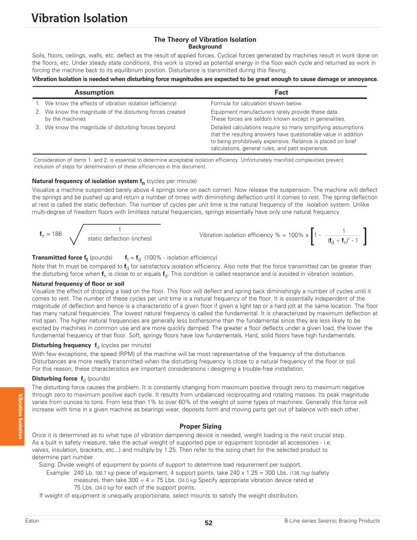
The Theory of Vibration IsolationBackground
Soils, floors, ceilings, walls, etc. deflect as the result of applied forces. Cyclical forces generated by machines result in work done onthe floors, etc. Under steady state conditions, this work is stored as potential energy in the floor each cycle and returned as work inforcing the machine back to its equilibrium position. Disturbance is transmitted during this flexing.Vibration Isolation is needed when disturbing force magnitudes are expected to be great enough to cause damage or annoyance.
Assumption Fact
1. We know the effects of vibration isolation (efficiency) Formula for calculation shown below.2. We know the magnitude of the disturbing forces created Equipment manufacturers rarely provide these data.
by the machines These forces are seldom known except in generalities.3. We know the magnitude of disturbing forces beyond Detailed calculations require so many simplifying assumptions
that the resulting answers have questionable value in additionto being prohibitively expensive. Reliance is placed on briefcalculations, general rules, and past experience.
Consideration of items 1. and 2. is essential to determine acceptable isolation efficiency. Unfortunately manifold complexities prevent inclusion of steps for determination of these efficiencies in this document.
Vibration Isolation
Proper SizingOnce it is determined as to what type of vibration dampening device is needed, weight loading is the next crucial step. As a built in safety measure, take the actual weight of supported pipe or equipment (consider all accessories - i.e. valves, insulation, brackets, etc...) and multiply by 1.25. Then refer to the sizing chart for the selected product to determine part number. Sizing: Divide weight of equipment by points of support to determine load requirement per support.Example: 240 Lb. (90.7 kg) piece of equipment, 4 support points, take 240 x 1.25 = 300 Lbs. (136.1kg) (safety
measure), then take 300 ÷ 4 = 75 Lbs. (34.0 kg) Specify appropriate vibration device rated at75 Lbs. (34.0 kg) for each of the support points.
If weight of equipment is unequally proportionate, select mounts to satisfy the weight distribution.
Natural frequency of isolation system fn (cycles per minute)Visualize a machine suspended barely above 4 springs (one on each corner). Now release the suspension. The machine will deflectthe springs and be pushed up and return a number of times with diminishing deflection until it comes to rest. The spring deflectionat rest is called the static deflection. The number of cycles per unit time is the natural frequency of the isolation system. Unlikemulti-degree of freedom floors with limitless natural frequencies, springs essentially have only one natural frequency.
Transmitted force ft (pounds) ft = fd (100% - isolation efficiency)Note that fn must be compared to fd for satisfactory isolation efficiency. Also note that the force transmitted can be greater thanthe disturbing force when fn is close to or equals fd. This condition is called resonance and is avoided in vibration isolation.
Natural frequency of floor or soilVisualize the effect of dropping a load on the floor. This floor will deflect and spring back diminishingly a number of cycles until itcomes to rest. The number of these cycles per unit time is a natural frequency of the floor. It is essentially independent of the magnitude of deflection and hence is a characteristic of a given floor if given a light tap or a hard jolt at the same location. The floorhas many natural frequencies. The lowest natural frequency is called the fundamental. It is characterized by maximum deflection atmid span. The higher natural frequencies are generally less bothersome than the fundamental since they are less likely to be excited by machines in common use and are more quickly damped. The greater a floor deflects under a given load, the lower thefundamental frequency of that floor. Soft, springy floors have low fundamentals. Hard, solid floors have high fundamentals.
Disturbing frequency fd (cycles per minute)With few exceptions, the speed (RPM) of the machine will be most representative of the frequency of the disturbance.Disturbances are more readily transmitted when the disturbing frequency is close to a natural frequency of the floor or soil.For this reason, these characteristics are important considerations i designing a trouble-free installation.
Disturbing force fd (pounds)The disturbing force causes the problem. It is constantly changing from maximum positive through zero to maximum negativethrough zero to maximum positive each cycle. It results from unbalanced reciprocating and rotating masses. Its peak magnitudevaries from ounces to tons. From less than 1% to over 60% of the weight of some types of machines. Generally this force willincrease with time in a given machine as bearings wear, deposits form and moving parts get out of balance with each other.
1static deflection (inches)
fn = 188 Vibration isolation efficiency % = 100% x 1 - 1
(fd ÷ fn)2 - 1[ ]
All dimensions in charts and on drawings are in inches. Dimensions shown in parentheses are in millimeters unless otherwise specified.
Vibration Isolation
53B-Line series Seismic Bracing Products Eaton
Vibration Isolation
Critical Installations96% to 99% Vibration Isolation Efficiency recommended (only 1% to 4% of disturbing vibration transmitted).
Standard Installations90% to 95% Vibration Isolation Efficiency recommended (only 5% to 10% of disturbing vibration transmitted).
Non-Critical Installations75% to 89% Vibration Isolation Efficiency recommended (only 11% to 24% of disturbing vibration transmitted).
For 1/4" (6.3mm) deflection: Specify B-Line series RM and RQ Neoprene Mountings or B-Line series RH Neoprene Hangers.
For 1/2" (12.7mm) deflection: Specify B-Line series RMD and RQD, (or JQTN fo OSHPD pre-approved) Neoprene Mountings or B-Line series RHD Neoprene Hangers.
For 1"-2" (25.4mm-50.8mm) deflection: Specify B-Line series CHSCS, CH30SCS, HHSCS, and HH30SCS Housed Spring Mountings.
For larger deflection requirements, consult factory.
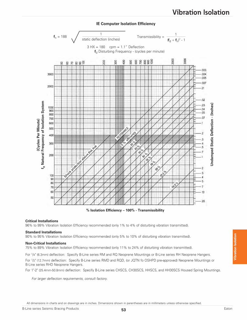
IE Computer Isolation Efficiency
1static deflection (inches)
fn = 188 Transmissibility = 1
(fd ÷ fn)2 - 1
3 HX = 180 cpm = 1.1” Deflectionfd Disturbing Frequency - (cycles per minute)
Undam
ped Static Deflection - (Inches)
% Isolation Efficiency – 100% - Transmissibility
(Cycles Per Minute)
f nNatural Frequency of Isolation System
All dimensions in charts and on drawings are in inches. Dimensions shown in parentheses are in millimeters unless otherwise specified.
Vibration Isolation
54 B-Line series Seismic Bracing ProductsEaton
Vibration Isolation
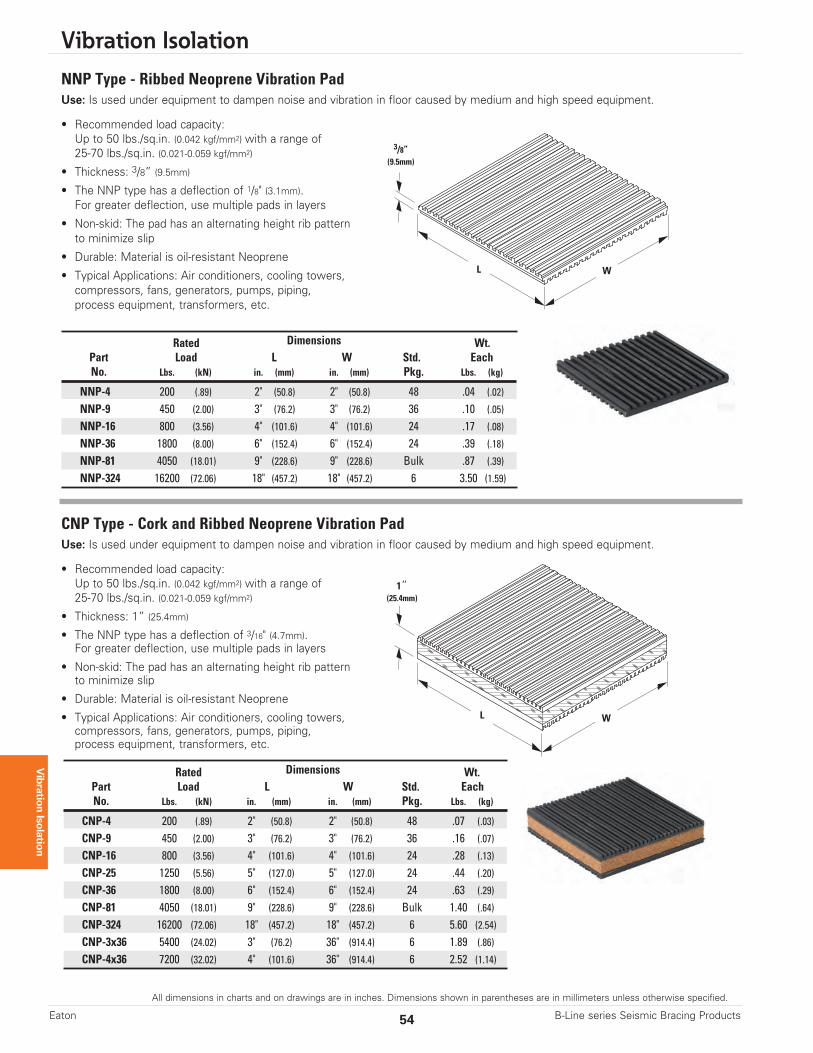
NNP Type - Ribbed Neoprene Vibration PadUse: Is used under equipment to dampen noise and vibration in floor caused by medium and high speed equipment.
• Recommended load capacity:Up to 50 lbs./sq.in. (0.042 kgf/mm2) with a range of25-70 lbs./sq.in. (0.021-0.059 kgf/mm2)
• Thickness: 3/8” (9.5mm)
• The NNP type has a deflection of 1/8" (3.1mm).For greater deflection, use multiple pads in layers
• Non-skid: The pad has an alternating height rib patternto minimize slip
• Durable: Material is oil-resistant Neoprene
• Typical Applications: Air conditioners, cooling towers,compressors, fans, generators, pumps, piping,process equipment, transformers, etc.
Rated Dimensions Wt.Part Load L W Std. EachNo. Lbs. (kN) in. (mm) in. (mm) Pkg. Lbs. (kg)
NNP-4 200 (.89) 2" (50.8) 2" (50.8) 48 .04 (.02)
NNP-9 450 (2.00) 3" (76.2) 3" (76.2) 36 .10 (.05)
NNP-16 800 (3.56) 4" (101.6) 4" (101.6) 24 .17 (.08)
NNP-36 1800 (8.00) 6" (152.4) 6" (152.4) 24 .39 (.18)
NNP-81 4050 (18.01) 9" (228.6) 9" (228.6) Bulk .87 (.39)
NNP-324 16200 (72.06) 18" (457.2) 18" (457.2) 6 3.50 (1.59)
3/8”(9.5mm)
L W
CNP Type - Cork and Ribbed Neoprene Vibration PadUse: Is used under equipment to dampen noise and vibration in floor caused by medium and high speed equipment.
• Recommended load capacity:Up to 50 lbs./sq.in. (0.042 kgf/mm2) with a range of25-70 lbs./sq.in. (0.021-0.059 kgf/mm2)
• Thickness: 1” (25.4mm)
• The NNP type has a deflection of 3/16" (4.7mm).For greater deflection, use multiple pads in layers
• Non-skid: The pad has an alternating height rib patternto minimize slip
• Durable: Material is oil-resistant Neoprene
• Typical Applications: Air conditioners, cooling towers,compressors, fans, generators, pumps, piping,process equipment, transformers, etc.
Rated Dimensions Wt.Part Load L W Std. EachNo. Lbs. (kN) in. (mm) in. (mm) Pkg. Lbs. (kg)
CNP-4 200 (.89) 2" (50.8) 2" (50.8) 48 .07 (.03)
CNP-9 450 (2.00) 3" (76.2) 3" (76.2) 36 .16 (.07)
CNP-16 800 (3.56) 4" (101.6) 4" (101.6) 24 .28 (.13)
CNP-25 1250 (5.56) 5" (127.0) 5" (127.0) 24 .44 (.20)
CNP-36 1800 (8.00) 6" (152.4) 6" (152.4) 24 .63 (.29)
CNP-81 4050 (18.01) 9" (228.6) 9" (228.6) Bulk 1.40 (.64)
CNP-324 16200 (72.06) 18" (457.2) 18" (457.2) 6 5.60 (2.54)CNP-3x36 5400 (24.02) 3" (76.2) 36" (914.4) 6 1.89 (.86)
CNP-4x36 7200 (32.02) 4" (101.6) 36" (914.4) 6 2.52 (1.14)
1”(25.4mm)
L W
All dimensions in charts and on drawings are in inches. Dimensions shown in parentheses are in millimeters unless otherwise specified.
Vibration Isolation
55B-Line series Seismic Bracing Products Eaton
Vibration Isolation
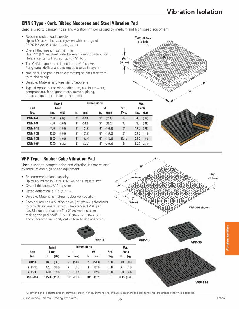
CNNK Type - Cork, Ribbed Neoprene and Steel Vibration PadUse: Is used to dampen noise and vibration in floor caused by medium and high speed equipment.
• Recommended load capacity:Up to 50 lbs./sq.in. (0.042 kgf/mm2) with a range of25-70 lbs./sq.in. (0.021-0.059 kgf/mm2)
• Overall thickness: 11/2” (38.1mm)Has 1/4” (6.3mm) steel plate for even weight distribution.Hole in center will accept up to 3/4” bolt
• The CNNK type has a deflection of 3/16" (4.7mm).For greater deflection, use multiple pads in layers
• Non-skid: The pad has an alternating height rib patternto minimize slip
• Durable: Material is oil-resistant Neoprene
• Typical Applications: Air conditioners, cooling towers,compressors, fans, generators, pumps, piping,process equipment, transformers, etc.
Rated Dimensions Wt.Part Load L W Std. EachNo. Lbs. (kN) in. (mm) in. (mm) Pkg. Lbs. (kg)
CNNK-4 200 (.89) 2" (50.8) 2" (50.8) 48 .40 (.18)
CNNK-9 450 (2.00) 3" (76.2) 3" (76.2) 36 .90 (.41)
CNNK-16 800 (3.56) 4" (101.6) 4" (101.6) 24 1.60 (.73)
CNNK-25 1250 (5.56) 5" (127.0) 5" (127.0) 24 2.50 (1.13)CNNK-36 1800 (8.00) 6" (152.4) 6" (152.4) Bulk 3.50 (1.59)CNNK-64 3200 (14.23) 8" (203.2) 8" (203.2) 6 6.20 (2.81)
11/2”(38.1mm)
13/16” (20.6mm)dia. hole
L W
VRP Type - Rubber Cube Vibration PadUse: Is used to dampen noise and vibration in floor causedby medium and high speed equipment.
• Recommended load capacity:Up to 45 lbs./sq.in. (0.038 kgf/mm2) per 1 square inch
• Overall thickness: 3/4” (19.0mm)
• Rated deflection is 3/16" (4.7mm).
• Durable: Material is natural rubber composition
• Each square has 4 suction holes (1/2" (12.7mm) diameter)to provide a non-skid effect. The standard VRP padhas 81 squares that are 2" x 2" (50.8mm x 50.8mm)making the pad itself 18" x 18" (457.2mm x 457.2mm).These squares are easily cut or torn to desired sizes.
Rated Dimensions Wt.Part Load L W Std. EachNo. Lbs. (kN) in. (mm) in. (mm) Pkg. Lbs. (kg)
VRP-4 180 (.80) 2" (50.8) 2" (50.8) Bulk .10 (.05)
VRP-16 720 (3.20) 4" (101.6) 4" (101.6) Bulk .41 (.19)
VRP-36 1620 (7.20) 6" (152.4) 6" (152.4) Bulk .90 (.41)
VRP-324 14580 (64.85) 18" (457.2) 18" (457.2) 3 8.15 (3.70)
VRP-36VRP-16VRP-4
VRP-324
VRP-324 shown
3/4”(19.0mm)
2”(50.8mm)
2”(50.8mm)
L
W
Vibration Isolation
56 B-Line series Seismic Bracing ProductsEaton
All dimensions in charts and on drawings are in inches. Dimensions shown in parentheses are in millimeters unless otherwise specified.
Vibration Isolation
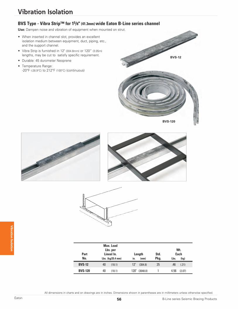
• When inserted in channel slot, provides an excellent isolation medium between equipment, duct, piping, etc., and the support channel.
• Vibra Strip is furnished in 12" (304.8mm) or 120” (3.05m)lengths, may be cut to satisfy specific requirement.
• Durable: 45 durometer Neoprene
• Temperature Range:-20°F (-28.9°C) to 212°F (100°C) (continuous)
Max. LoadLbs. per Wt.
Part Lineal In. Length Std. EachNo. Lbs. (kg/25.4 mm) in. (mm) Pkg. Lbs. (kg)
BVS-12 40 (18.1) 12" (304.8) 25 .46 (.21)
BVS-120 40 (18.1) 120" (3048.0) 1 4.56 (2.07)
BVS-12
BVS-120
BVS Type - Vibra Strip™ for 15/8" (41.3mm)wide Eaton B-Line series channelUse: Dampen noise and vibration of equipment when mounted on strut.

All dimensions in charts and on drawings are in inches. Dimensions shown in parentheses are in millimeters unless otherwise specified.
Vibration Isolation
57B-Line series Seismic Bracing Products Eaton
Vibration Isolation
RM & RM-D Type - Neoprene MountUse: To minimize or prevent noise and vibration from transferring between equipment and floor or solid support structure.Typical applications include air handling units, air conditioners, compressors, pumps, machine tools, motors, businessmachines, transformers, furnaces, etc.
OT
(thread)
S
K
J H
Dimensions
L S W O T K H JMount RM RM-D RM RM-DSize in. (mm) in. (mm) in. (mm) in. (mm) in. (mm) in. (mm) in. (mm) in. (mm) in. (mm)
A 33/16 (81.0) 23/8 (27.8) 113/16 (47.5) 11/32 (8.7) 5/16”-18 11/4 (31.7) 1 (25.4) 11/2 (38.1) 13/16 (20.6) 15/16 (33.3)
B 37/8 (98.4) 3 (76.2) 23/8 (60.3) 11/32 (8.7) 3/8”-16 13/4 (44.4) 11/4 (31.7) 113/16 (46.0) 11/32 (26.2) 19/16 (39.7)
C 51/2 (134.7) 41/8 (104.8) 31/4 (82.5) 9/16 (14.3) 1/2”-13 21/2 (63.5) 11/2 (38.1) 21/2 (63.5) 11/4 (31.7) 21/4 (57.1)
F 71/2 (190.5) 61/8 (155.6) 47/8 (123.8) 9/16 (14.3) 5/8”-11 43/8 (111.1) 15/8 (41.3) 23/4 (69.8) 13/8 (34.9) 21/2 (63.5)
Typical Part Numbering
RM - 80 A
Type Load Mount Size
Part Mount Maximum ColorNo. Size Load Code
Lbs. (kN)
RM-40A A 40 (0.18) OrangeRM-55A A 55 (.0.25) YellowRM-80A A 80 (0.35) GreenRM-130A A 130 (0.58) Blue
RM-120B B 120 (0.53) OrangeRM-200B B 200 (.0.89) YellowRM-280B B 280 (1.24) GreenRM-400B B 400 (1.78) Blue
RM-300C C 300 (.1.33) YellowRM-520C C 520 (2.31) GreenRM-750C C 750 (3.33) BlueRM-1100C C 1100 (4.89) White
RM-1800F F 1800 (8.00) GreenRM-3000F F 3000 (13.3) BlueRM-5000F F 5000 (22.2) Green
RM Series for 1/4” (6.3mm) Deflection
Part Mount Maximum ColorNo. Size Load Code
Lbs. (kN)
RM-D-40A A 40 (0.18) OrangeRM-D-55A A 55 (.0.25) YellowRM-D-80A A 80 (0.35) GreenRM-D-130A A 130 (0.58) Blue
RM-D-120B B 120 (0.53) OrangeRM-D-200B B 200 (.0.89) YellowRM-D-280B B 280 (1.24) GreenRM-D-400B B 400 (1.78) Blue
RM-D-300C C 300 (.1.33) YellowRM-D-520C C 520 (2.31) GreenRM-D-750C C 750 (3.33) BlueRM-D-1100C C 1100 (4.89) White
RM-D-1800F F 1800 (8.00) GreenRM-D-3000F F 3000 (13.3) BlueRM-D-5000F F 5000 (22.2) Green
RM-D Series for 1/2” (12.7mm) Deflection
1/4” (6.3mm)Deflection
1/2” (12.7mm)Deflection
L
W
Vibration Isolation
58 B-Line series Seismic Bracing ProductsEaton
All dimensions in charts and on drawings are in inches. Dimensions shown in parentheses are in millimeters unless otherwise specified.
Vibration Isolation
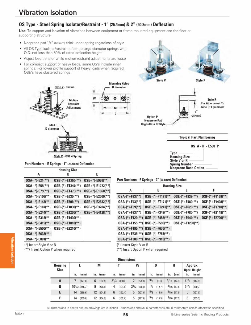
OS Type - Steel Spring Isolator/Restraint - 1” (25.4mm) & 2” (50.8mm) DeflectionUse: To support and isolation of vibrations between equipment or frame mounted equipment and the floor orsupporting structure
Dimensions
Housing L M T W D H Approx.Size Oper. Height
in. (mm) in. (mm) in. (mm) in. (mm) in. (mm) in. (mm) in. (mm)
A 7 (177.8) 6 (152.4) 23/4 (69.8) 2 (50.8) 3/8 (9.5) 9/16 (14.3) 41/2 (114.3)
B 101/2 (266.7) 9 (228.6) 4 (101.6) 31/2 (88.9) 1/2 (12.7) 11/16 (17.5) 51/2 (139.7)
E 14 (355.6) 12 (304.8) 6 (152.4) 5 (127.0) 5/8 (15.9) 11/16 (17.5) 5 (127.0)
F 14 (355.6) 12 (304.8) 6 (152.4) 5 (127.0) 5/8 (15.9) 11/16 (17.5) 8 (203.3)
Housing SizeA B E
OSA-(*)-E21(**) OSB-(*)-ET255(**) OSE-(*)-E976(**)OSA-(*)-E55(**) OSB-(*)-ET347(**) OSE-(*)-E1272(**)OSA-(*)-E79(**) OSB-(*)-ET473(**) OSE-(*)-E1660(**)OSA-(*)-E106(**) OSB-(*)-E630(**) OSE-(*)-E2000(**)OSA-(*)-E143(**) OSB-(*)-E806(**) OSE-(*)-E2532(**)OSA-(*)-E187(**) OSB-(*)-E1030(**) OSE-(*)-E3204(**)OSA-(*)-E244(**) OSB-(*)-E1230(**) OSE-(*)-E4128(**)OSA-(*)-E318(**) OSB-(*)-E1430(**)OSA-(*)-E415(**) OSB-(*)-E1810(**)OSA-(*)-E500(**) OSB-(*)-E2210(**)OSA-(*)-E633(**)OSA-(*)-E801(**)
(*) Insert Style V or R(**) Insert Option P when required
Part Numbers - E Springs - 1” (25.4mm) Deflection
Housing SizeA B E F
OSA-(*)-F33(**) OSB-(*)-FT121(**) OSE-(*)-F332(**) OSF-(*)-F1159(**)OSA-(*)-F43(**) OSB-(*)-FT171(**) OSE-(*)-F480(**) OSF-(*)-F1408(**)OSA-(*)-F59(**) OSB-(*)-FT241(**) OSE-(*)-F620(**) OSF-(*)-F1710(**)OSA-(*)-F83(**) OSB-(*)-F348(**) OSE-(*)-F780(**) OSF-(*)-F2149(**)OSA-(*)-F120(**) OSB-(*)-F453(**) OSE-(*)-F944(**) OSF-(*)-F2700(**)OSA-(*)-F155(**) OSB-(*)-F590(**) OSE-(*)-F1200(**)OSA-(*)-F195(**) OSB-(*)-F676(**)OSA-(*)-F236(**) OSB-(*)-F787(**)OSA-(*)-F300(**) OSB-(*)-F918(**)
(*) Insert Style V or R(**) Insert Option P when required
Part Numbers - F Springs - 2” (50.8mm) Deflection
• Neoprene pad 1/4” (6.3mm) thick under spring regardless of style
• All OS Type isolator/restraints feature large diameter springs with O.D. not less than 80% of rated deflection height
• Adjust load transfer while motion restraint adjustments are loose
• For compact support of heavy loads, some OS’s include innersprings. For lower profile support of heavy loads when required,OSE’s have clustered springs
Typical Part Numbering
OS A - R - E500 P
TypeHousing SizeStyle V or RSpring NumberNeoprene Base Option
StudD diameter
W
Mounting HolesH diameter
M
L
MotionRestraintAdjustment
Option P -Neoprene Pad
Regardless Of Style
Style R -For Attachment ToSide Of Equipment
Style V - OSE 4 Spring
Style V - shown
Style V Style R
1”(25.4mm)
All dimensions in charts and on drawings are in inches. Dimensions shown in parentheses are in millimeters unless otherwise specified.
Vibration Isolation
59B-Line series Seismic Bracing Products Eaton
Vibration Isolation
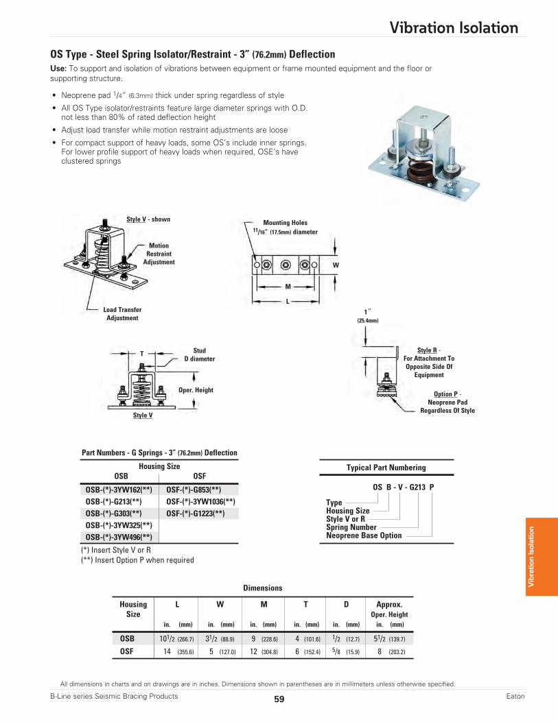
OS Type - Steel Spring Isolator/Restraint - 3” (76.2mm) DeflectionUse: To support and isolation of vibrations between equipment or frame mounted equipment and the floor orsupporting structure.
Dimensions
Housing L W M T D Approx.Size Oper. Height
in. (mm) in. (mm) in. (mm) in. (mm) in. (mm) in. (mm)
OSB 101/2 (266.7) 31/2 (88.9) 9 (228.6) 4 (101.6) 1/2 (12.7) 51/2 (139.7)
OSF 14 (355.6) 5 (127.0) 12 (304.8) 6 (152.4) 5/8 (15.9) 8 (203.2)
Housing SizeOSB OSF
OSB-(*)-3YW162(**) OSF-(*)-G853(**)OSB-(*)-G213(**) OSF-(*)-3YW1036(**)OSB-(*)-G303(**) OSF-(*)-G1223(**)OSB-(*)-3YW325(**)OSB-(*)-3YW496(**)
(*) Insert Style V or R(**) Insert Option P when required
Part Numbers - G Springs - 3” (76.2mm) Deflection
• Neoprene pad 1/4” (6.3mm) thick under spring regardless of style
• All OS Type isolator/restraints feature large diameter springs with O.D.not less than 80% of rated deflection height
• Adjust load transfer while motion restraint adjustments are loose
• For compact support of heavy loads, some OS’s include inner springs.For lower profile support of heavy loads when required, OSE’s haveclustered springs
Typical Part Numbering
OS B - V - G213 P
TypeHousing SizeStyle V or RSpring NumberNeoprene Base Option
StudD diameter
W
Mounting Holes11/16” (17.5mm) diameter
M
T
LLoad TransferAdjustment
MotionRestraintAdjustment
Oper. Height Option P -Neoprene Pad
Regardless Of Style
Style R -For Attachment ToOpposite Side Of
Equipment
Style V
Style V - shown
1”(25.4mm)
Vibration Isolation
60 B-Line series Seismic Bracing ProductsEaton
All dimensions in charts and on drawings are in inches. Dimensions shown in parentheses are in millimeters unless otherwise specified.
Vibration Isolation
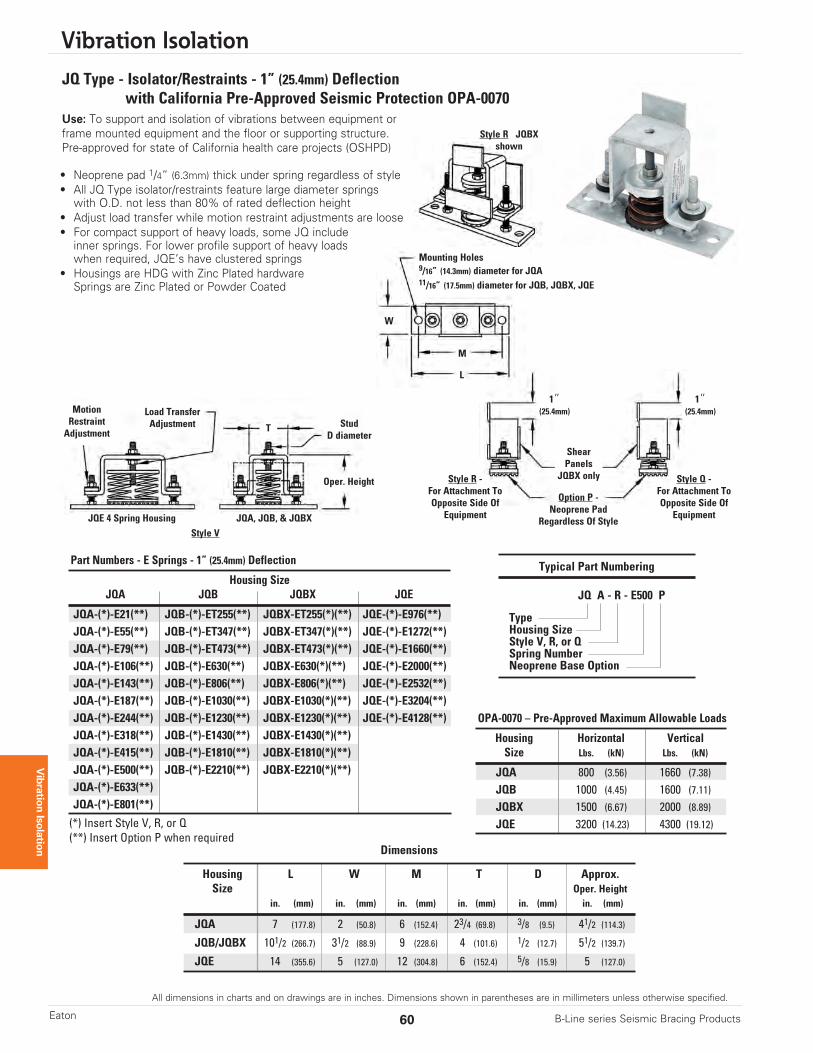
JQ Type - Isolator/Restraints - 1” (25.4mm) Deflectionwith California Pre-Approved Seismic Protection OPA-0070
Use: To support and isolation of vibrations between equipment orframe mounted equipment and the floor or supporting structure.Pre-approved for state of California health care projects (OSHPD)
• Neoprene pad 1/4” (6.3mm) thick under spring regardless of style• All JQ Type isolator/restraints feature large diameter springswith O.D. not less than 80% of rated deflection height
• Adjust load transfer while motion restraint adjustments are loose• For compact support of heavy loads, some JQ includeinner springs. For lower profile support of heavy loadswhen required, JQE’s have clustered springs
• Housings are HDG with Zinc Plated hardwareSprings are Zinc Plated or Powder Coated
Dimensions
Housing L W M T D Approx.Size Oper. Height
in. (mm) in. (mm) in. (mm) in. (mm) in. (mm) in. (mm)
JQA 7 (177.8) 2 (50.8) 6 (152.4) 23/4 (69.8) 3/8 (9.5) 41/2 (114.3)
JQB/JQBX 101/2 (266.7) 31/2 (88.9) 9 (228.6) 4 (101.6) 1/2 (12.7) 51/2 (139.7)
JQE 14 (355.6) 5 (127.0) 12 (304.8) 6 (152.4) 5/8 (15.9) 5 (127.0)
Typical Part Numbering
JQ A - R - E500 P
TypeHousing SizeStyle V, R, or QSpring NumberNeoprene Base Option
Housing Horizontal VerticalSize Lbs. (kN) Lbs. (kN)
JQA 800 (3.56) 1660 (7.38)JQB 1000 (4.45) 1600 (7.11)JQBX 1500 (6.67) 2000 (8.89)JQE 3200 (14.23) 4300 (19.12)
OPA-0070 – Pre-Approved Maximum Allowable Loads
Housing SizeJQA JQB JQBX JQE
JQA-(*)-E21(**) JQB-(*)-ET255(**) JQBX-ET255(*)(**) JQE-(*)-E976(**)JQA-(*)-E55(**) JQB-(*)-ET347(**) JQBX-ET347(*)(**) JQE-(*)-E1272(**)JQA-(*)-E79(**) JQB-(*)-ET473(**) JQBX-ET473(*)(**) JQE-(*)-E1660(**)JQA-(*)-E106(**) JQB-(*)-E630(**) JQBX-E630(*)(**) JQE-(*)-E2000(**)JQA-(*)-E143(**) JQB-(*)-E806(**) JQBX-E806(*)(**) JQE-(*)-E2532(**)JQA-(*)-E187(**) JQB-(*)-E1030(**) JQBX-E1030(*)(**) JQE-(*)-E3204(**)JQA-(*)-E244(**) JQB-(*)-E1230(**) JQBX-E1230(*)(**) JQE-(*)-E4128(**)JQA-(*)-E318(**) JQB-(*)-E1430(**) JQBX-E1430(*)(**)JQA-(*)-E415(**) JQB-(*)-E1810(**) JQBX-E1810(*)(**)JQA-(*)-E500(**) JQB-(*)-E2210(**) JQBX-E2210(*)(**)JQA-(*)-E633(**)JQA-(*)-E801(**)
(*) Insert Style V, R, or Q(**) Insert Option P when required
Part Numbers - E Springs - 1” (25.4mm) Deflection
StudD diameter
T
Load TransferAdjustment
JQE 4 Spring Housing JQA, JQB, & JQBX
MotionRestraintAdjustment
Oper. Height
ShearPanels
JQBX only
Option P -Neoprene Pad
Regardless Of Style
Style R -For Attachment ToOpposite Side Of
Equipment
Style Q -For Attachment ToOpposite Side Of
Equipment
Style V
Style R JQBXshown
W
Mounting Holes9/16” (14.3mm) diameter for JQA11/16” (17.5mm) diameter for JQB, JQBX, JQE
M
L
1”(25.4mm)
1”(25.4mm)
All dimensions in charts and on drawings are in inches. Dimensions shown in parentheses are in millimeters unless otherwise specified.
Vibration Isolation
61B-Line series Seismic Bracing Products Eaton
Vibration Isolation
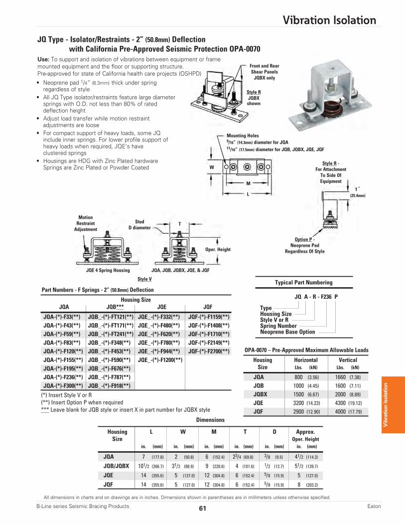
• Neoprene pad 1/4” (6.3mm) thick under springregardless of style
• All JQ Type isolator/restraints feature large diametersprings with O.D. not less than 80% of rateddeflection height
• Adjust load transfer while motion restraintadjustments are loose
• For compact support of heavy loads, some JQ include inner springs. For lower profile support of heavy loads when required, JQE’s haveclustered springs
• Housings are HDG with Zinc Plated hardwareSprings are Zinc Plated or Powder Coated
Dimensions
Housing L W M T D Approx.Size Oper. Height
in. (mm) in. (mm) in. (mm) in. (mm) in. (mm) in. (mm)
JQA 7 (177.8) 2 (50.8) 6 (152.4) 23/4 (69.8) 3/8 (9.5) 41/2 (114.3)
JQB/JQBX 101/2 (266.7) 31/2 (88.9) 9 (228.6) 4 (101.6) 1/2 (12.7) 51/2 (139.7)
JQE 14 (355.6) 5 (127.0) 12 (304.8) 6 (152.4) 5/8 (15.9) 5 (127.0)
JQF 14 (355.6) 5 (127.0) 12 (304.8) 6 (152.4) 5/8 (15.9) 8 (203.2)
Typical Part Numbering
JQ A - R - F236 P
TypeHousing SizeStyle V or RSpring NumberNeoprene Base Option
Housing Horizontal VerticalSize Lbs. (kN) Lbs. (kN)
JQA 800 (3.56) 1660 (7.38)JQB 1000 (4.45) 1600 (7.11)JQBX 1500 (6.67) 2000 (8.89)JQE 3200 (14.23) 4300 (19.12)JQF 2900 (12.90) 4000 (17.79)
OPA-0070 – Pre-Approved Maximum Allowable Loads
Housing SizeJQA JQB*** JQE JQF
JQA-(*)-F33(**) JQB_-(*)-FT121(**) JQE_-(*)-F332(**) JQF-(*)-F1159(**)JQA-(*)-F43(**) JQB_-(*)-FT171(**) JQE_-(*)-F480(**) JQF-(*)-F1408(**)JQA-(*)-F59(**) JQB_-(*)-FT241(**) JQE_-(*)-F620(**) JQF-(*)-F1710(**)JQA-(*)-F83(**) JQB_-(*)-F348(**) JQE_-(*)-F780(**) JQF-(*)-F2149(**)JQA-(*)-F120(**) JQB_-(*)-F453(**) JQE_-(*)-F944(**) JQF-(*)-F2700(**)JQA-(*)-F155(**) JQB_-(*)-F590(**) JQE_-(*)-F1200(**)JQA-(*)-F195(**) JQB_-(*)-F676(**)JQA-(*)-F236(**) JQB_-(*)-F787(**)JQA-(*)-F300(**) JQB_-(*)-F918(**)
(*) Insert Style V or R(**) Insert Option P when required*** Leave blank for JQB style or insert X in part number for JQBX style
Part Numbers - F Springs - 2” (50.8mm) Deflection
StudD diameter
W
1”(25.4mm)
Mounting Holes9/16” (14.3mm) diameter for JQA11/16” (17.5mm) diameter for JQB, JQBX, JQE, JQF
M
T
L
Front and RearShear PanelsJQBX only
JQE 4 Spring Housing JQA, JQB, JQBX, JQE, & JQF
MotionRestraintAdjustment
Oper. Height
Option P -Neoprene Pad
Regardless Of Style
Style R -For AttachmentTo Side OfEquipment
Style V
Style RJQBXshown
JQ Type - Isolator/Restraints - 2” (50.8mm) Deflectionwith California Pre-Approved Seismic Protection OPA-0070
Use: To support and isolation of vibrations between equipment or framemounted equipment and the floor or supporting structure.Pre-approved for state of California health care projects (OSHPD)
Vibration Isolation
62 B-Line series Seismic Bracing ProductsEaton
All dimensions in charts and on drawings are in inches. Dimensions shown in parentheses are in millimeters unless otherwise specified.
Vibration Isolation
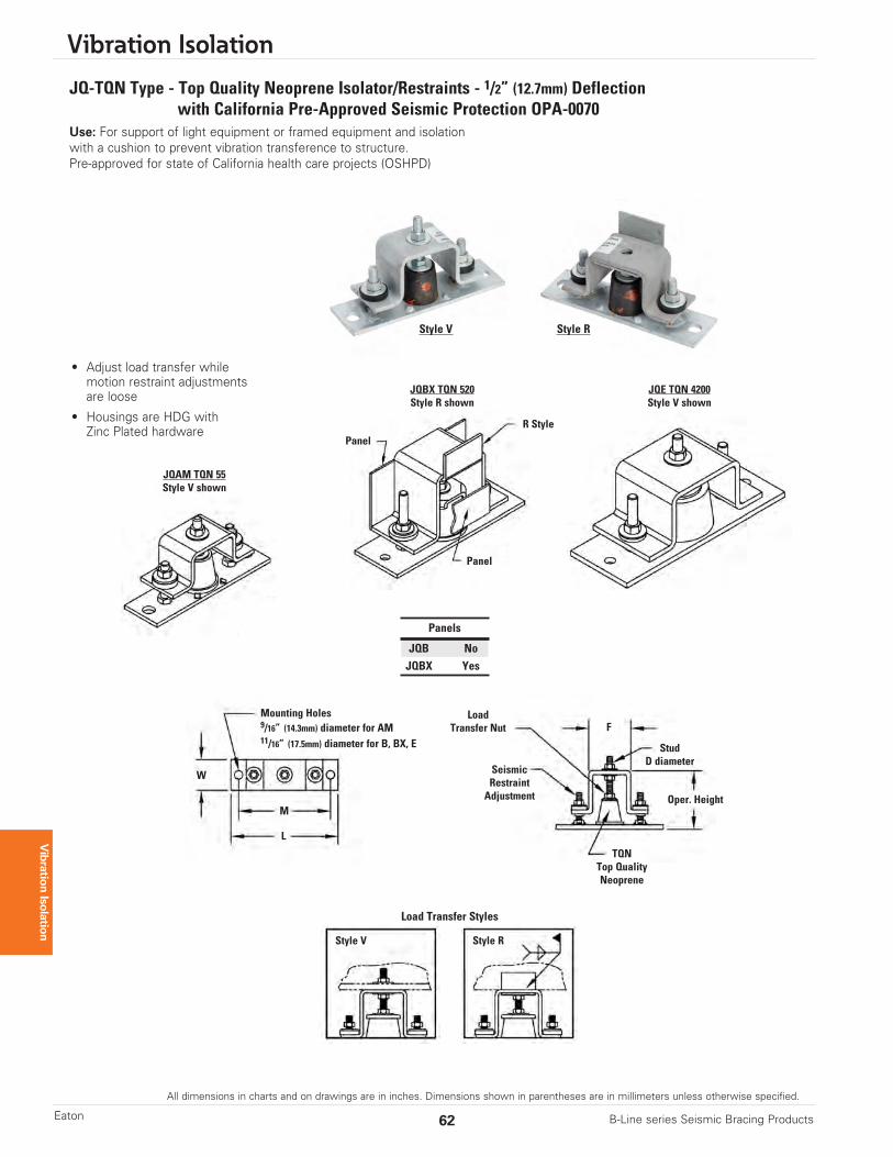
JQ-TQN Type - Top Quality Neoprene Isolator/Restraints - 1/2” (12.7mm) Deflectionwith California Pre-Approved Seismic Protection OPA-0070
Use: For support of light equipment or framed equipment and isolationwith a cushion to prevent vibration transference to structure.Pre-approved for state of California health care projects (OSHPD)
• Adjust load transfer whilemotion restraint adjustmentsare loose
• Housings are HDG withZinc Plated hardware
Panel
Panel
R Style
W
Mounting Holes9/16” (14.3mm) diameter for AM11/16” (17.5mm) diameter for B, BX, E
M
L
StudD diameter
TQNTop QualityNeoprene
F
Oper. Height
Style V
Load Transfer Styles
Style R
LoadTransfer Nut
SeismicRestraintAdjustment
Panels
JQB NoJQBX Yes
JQAM TQN 55Style V shown
JQBX TQN 520Style R shown
JQE TQN 4200Style V shown
Style V Style R
All dimensions in charts and on drawings are in inches. Dimensions shown in parentheses are in millimeters unless otherwise specified.
Vibration Isolation
63B-Line series Seismic Bracing Products Eaton
Vibration Isolation
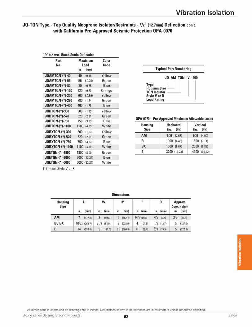
JQ-TQN Type - Top Quality Neoprene Isolator/Restraints - 1/2” (12.7mm) Deflection con’t.with California Pre-Approved Seismic Protection OPA-0070
Part Maximum ColorNo. Load Code
in. (mm)
JQAMTQN-(*)-40 40 (0.18) YellowJQAMTQN-(*)-55 55 (.0.25) GreenJQAMTQN-(*)-80 80 (0.35) BlueJQAMTQN-(*)-120 120 (0.53) OrangeJQAMTQN-(*)-200 200 (.0.89) YellowJQAMTQN-(*)-280 280 (1.24) GreenJQAMTQN-(*)-400 400 (1.78) Blue
JQBTQN-(*)-300 300 (1.33) YellowJQBTQN-(*)-520 520 (2.31) GreenJQBTQN-(*)-750 750 (3.33) BlueJQBTQN-(*)-1100 1100 (4.89) White
JQBXTQN-(*)-300 300 (1.33) YellowJQBXTQN-(*)-520 520 (2.31) GreenJQBXTQN-(*)-750 750 (3.33) BlueJQBXTQN-(*)-1100 1100 (4.89) White
JQETQN-(*)-1800 1800 (8.00) GreenJQETQN-(*)-3000 3000 (13.34) BlueJQETQN-(*)-5000 5000 (22.24) White
(*) Insert Style V or R
1/2” (12.7mm) Rated Static Deflection
Dimensions
Housing L W M F D Approx.Size Oper. Height
in. (mm) in. (mm) in. (mm) in. (mm) in. (mm) in. (mm)
AM 7 (177.8) 2 (50.8) 6 (152.4) 23/4 (69.8) 3/8 (9.5) 23/4 (69.8)
B / BX 101/2 (266.7) 31/2 (88.9) 9 (228.6) 4 (101.6) 1/2 (12.7) 5 (127.0)
E 14 (355.6) 5 (127.0) 12 (304.8) 6 (152.4) 5/8 (15.9) 5 (127.0)
Typical Part Numbering
JQ AM TQN - V - 200
TypeHousing SizeTQN IsolatorStyle V or RLoad Rating
Housing Horizontal VerticalSize Lbs. (kN) Lbs. (kN)
AM 600 (2.67) 900 (4.00)
B 1000 (4.45) 1600 (7.11)BX 1500 (6.67) 2000 (8.89)E 3200 (14.23) 4300 (109.22)
OPA-0070 – Pre-Approved Maximum Allowable Loads
Vibration Isolation
64 B-Line series Seismic Bracing ProductsEaton
All dimensions in charts and on drawings are in inches. Dimensions shown in parentheses are in millimeters unless otherwise specified.
Vibration Isolation
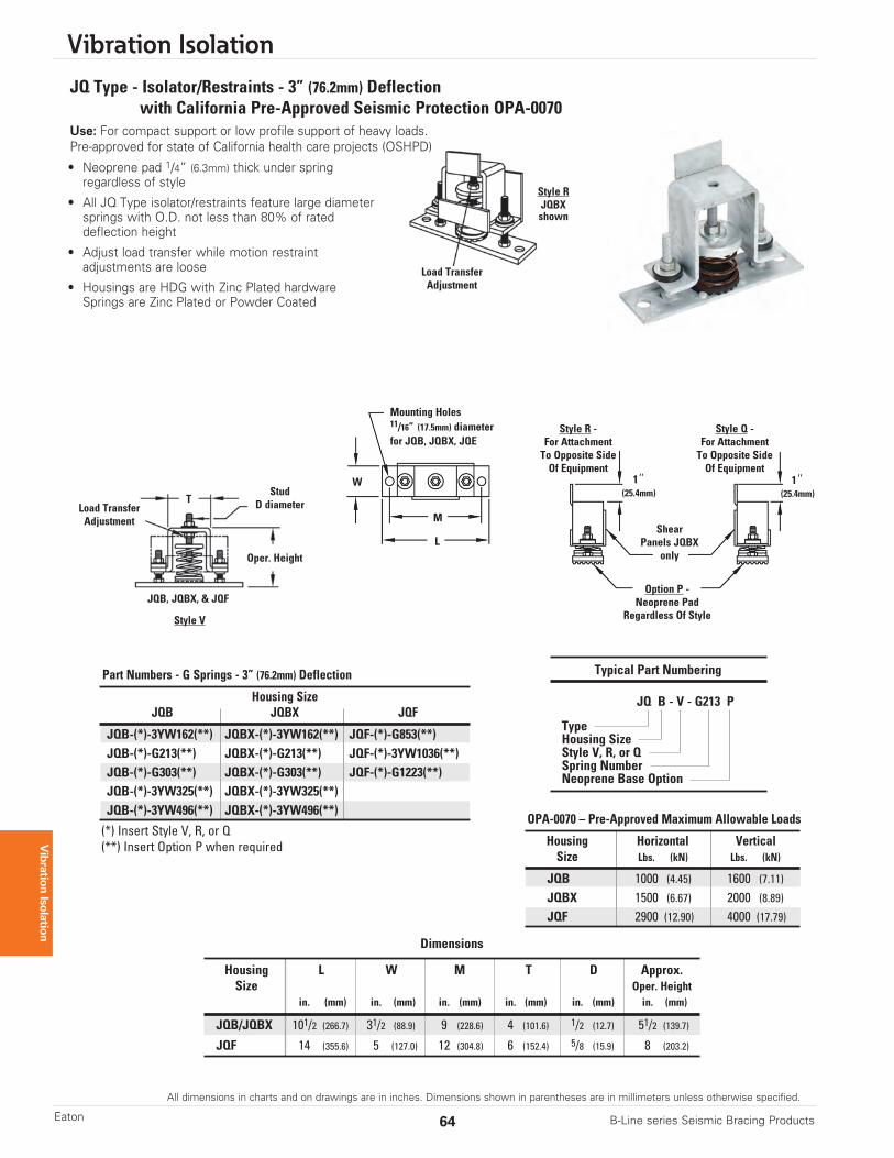
Dimensions
Housing L W M T D Approx.Size Oper. Height
in. (mm) in. (mm) in. (mm) in. (mm) in. (mm) in. (mm)
JQB/JQBX 101/2 (266.7) 31/2 (88.9) 9 (228.6) 4 (101.6) 1/2 (12.7) 51/2 (139.7)
JQF 14 (355.6) 5 (127.0) 12 (304.8) 6 (152.4) 5/8 (15.9) 8 (203.2)
Typical Part Numbering
JQ B - V - G213 P
TypeHousing SizeStyle V, R, or QSpring NumberNeoprene Base Option
Housing Horizontal VerticalSize Lbs. (kN) Lbs. (kN)
JQB 1000 (4.45) 1600 (7.11)JQBX 1500 (6.67) 2000 (8.89)JQF 2900 (12.90) 4000 (17.79)
OPA-0070 – Pre-Approved Maximum Allowable Loads
StudD diameter
W 1”(25.4mm)
1”(25.4mm)
Mounting Holes11/16” (17.5mm) diameterfor JQB, JQBX, JQE
M
T
LShear
Panels JQBXonly
JQB, JQBX, & JQF
Oper. Height
Option P -Neoprene Pad
Regardless Of Style
Style R -For AttachmentTo Opposite SideOf Equipment
Style Q -For AttachmentTo Opposite SideOf Equipment
Style V
Style RJQBXshown
Load TransferAdjustment
Load TransferAdjustment
Housing SizeJQB JQBX JQF
JQB-(*)-3YW162(**) JQBX-(*)-3YW162(**) JQF-(*)-G853(**)JQB-(*)-G213(**) JQBX-(*)-G213(**) JQF-(*)-3YW1036(**)JQB-(*)-G303(**) JQBX-(*)-G303(**) JQF-(*)-G1223(**)JQB-(*)-3YW325(**) JQBX-(*)-3YW325(**)JQB-(*)-3YW496(**) JQBX-(*)-3YW496(**)
(*) Insert Style V, R, or Q(**) Insert Option P when required
Part Numbers - G Springs - 3” (76.2mm) Deflection
JQ Type - Isolator/Restraints - 3” (76.2mm) Deflectionwith California Pre-Approved Seismic Protection OPA-0070
Use: For compact support or low profile support of heavy loads.Pre-approved for state of California health care projects (OSHPD)
• Neoprene pad 1/4” (6.3mm) thick under springregardless of style
• All JQ Type isolator/restraints feature large diametersprings with O.D. not less than 80% of rateddeflection height
• Adjust load transfer while motion restraintadjustments are loose
• Housings are HDG with Zinc Plated hardwareSprings are Zinc Plated or Powder Coated
All dimensions in charts and on drawings are in inches. Dimensions shown in parentheses are in millimeters unless otherwise specified.
Vibration Isolation
65B-Line series Seismic Bracing Products Eaton
Vibration Isolation
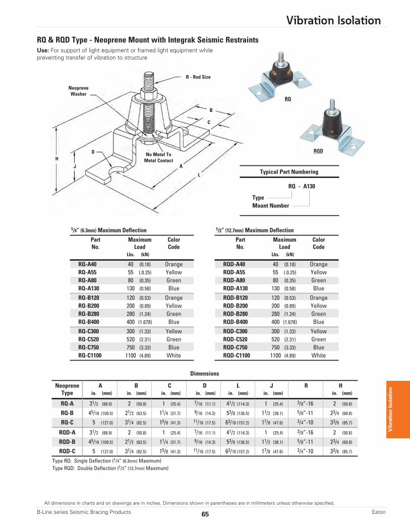
RQ & RQD Type - Neoprene Mount with Integrak Seismic RestraintsUse: For support of light equipment or framed light equipment whilepreventing transfer of vibration to structure
Dimensions
Neoprene A B C D L J R HType in. (mm) in. (mm) in. (mm) in. (mm) in. (mm) in. (mm) in. (mm)
RQ-A 31/2 (88.9) 2 (50.8) 1 (25.4) 7/16 (11.1) 41/2 (114.3) 1 (25.4) 3/8”-16 2 (50.8)
RQ-B 45/16 (109.5) 21/2 (63.5) 11/4 (31.7) 9/16 (14.3) 53/8 (136.5) 11/2 (38.1) 5/8”-11 23/4 (69.8)
RQ-C 5 (127.0) 31/4 (82.5) 15/8 (41.3) 11/16 (17.5) 63/16 (157.2) 17/8 (47.6) 3/4”-10 33/8 (85.7)
RQD-A 31/2 (88.9) 2 (50.8) 1 (25.4) 7/16 (11.1) 41/2 (114.3) 1 (25.4) 3/8”-16 2 (50.8)
RQD-B 45/16 (109.5) 21/2 (63.5) 11/4 (31.7) 9/16 (14.3) 53/8 (136.5) 11/2 (38.1) 5/8”-11 23/4 (69.8)
RQD-C 5 (127.0) 31/4 (82.5) 15/8 (41.3) 11/16 (17.5) 63/16 (157.2) 17/8 (47.6) 3/4”-10 33/8 (85.7)
Type RQ: Single Deflection (1/4” (6.3mm) Maximum)Type RQD: Double Deflection (1/2” (12.7mm) Maximum)
R - Rod Size
H
J
D
L
A
B
C
No Metal ToMetal Contact
NeopreneWasher
Part Maximum ColorNo. Load Code
Lbs. (kN)
RQD-A40 40 (0.18) OrangeRQD-A55 55 (.0.25) YellowRQD-A80 80 (0.35) GreenRQD-A130 130 (0.58) Blue
RQD-B120 120 (0.53) OrangeRQD-B200 200 (0.89) YellowRQD-B280 280 (1.24) GreenRQD-B400 400 (1.678) Blue
RQD-C300 300 (1.33) YellowRQD-C520 520 (2.31) GreenRQD-C750 750 (3.33) BlueRQD-C1100 1100 (4.89) White
1/2” (12.7mm) Maximum Deflection
Part Maximum ColorNo. Load Code
Lbs. (kN)
RQ-A40 40 (0.18) OrangeRQ-A55 55 (.0.25) YellowRQ-A80 80 (0.35) GreenRQ-A130 130 (0.58) Blue
RQ-B120 120 (0.53) OrangeRQ-B200 200 (0.89) YellowRQ-B280 280 (1.24) GreenRQ-B400 400 (1.678) Blue
RQ-C300 300 (1.33) YellowRQ-C520 520 (2.31) GreenRQ-C750 750 (3.33) BlueRQ-C1100 1100 (4.89) White
1/4” (6.3mm) Maximum Deflection
Typical Part Numbering
RQ - A130
TypeMount Number
RQ
RQD
Vibration Isolation
66 B-Line series Seismic Bracing ProductsEaton
All dimensions in charts and on drawings are in inches. Dimensions shown in parentheses are in millimeters unless otherwise specified.
Vibration Isolation
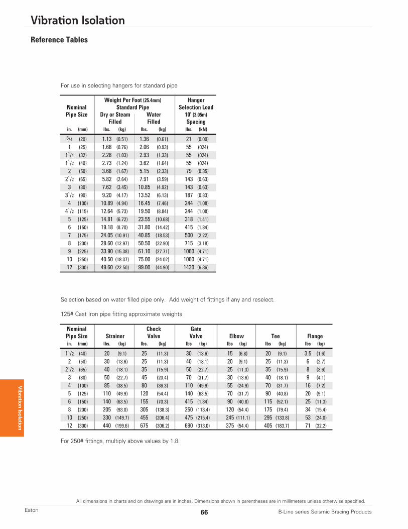
Reference Tables
For use in selecting hangers for standard pipe
Selection based on water filled pipe only. Add weight of fittings if any and reselect.
125# Cast Iron pipe fitting approximate weights
For 250# fittings, multiply above values by 1.8.
Weight Per Foot (25.4mm) HangerNominal Standard Pipe Selection LoadPipe Size Dry or Steam Water 10’ (3.05m)
Filled Filled Spacingin. (mm) lbs. (kg) lbs. (kg) lbs. (kN)
3/4 (20) 1.13 (0.51) 1.36 (0.61) 21 (0.09)1 (25) 1.68 (0.76) 2.06 (0.93) 55 (024)11/4 (32) 2.28 (1.03) 2.93 (1.33) 55 (024)11/2 (40) 2.73 (1.24) 3.62 (1.64) 55 (024)2 (50) 3.68 (1.67) 5.15 (2.33) 79 (0.35)21/2 (65) 5.82 (2.64) 7.91 (3.59) 143 (0.63)3 (80) 7.62 (3.45) 10.85 (4.92) 143 (0.63)31/2 (90) 9.20 (4.17) 13.52 (6.13) 187 (0.83)4 (100) 10.89 (4.94) 16.45 (7.46) 244 (1.08)41/2 (115) 12.64 (5.73) 19.50 (8.84) 244 (1.08)5 (125) 14.81 (6.72) 23.55 (10.68) 318 (1.41)6 (150) 19.18 (8.70) 31.80 (14.42) 415 (1.84)7 (175) 24.05 (10.91) 40.85 (18.53) 500 (2.22)8 (200) 28.60 (12.97) 50.50 (22.90) 715 (3.18)9 (225) 33.90 (15.38) 61.10 (27.71) 1060 (4.71)10 (250) 40.50 (18.37) 75.00 (24.02) 1060 (4.71)12 (300) 49.60 (22.50) 99.00 (44.90) 1430 (6.36)
Nominal Check GatePipe Size Strainer Valve Valve Elbow Tee Flangein. (mm) lbs. (kg) lbs. (kg) lbs (kg) lbs (kg) lbs (kg) lbs (kg)
11/2 (40) 20 (9.1) 25 (11.3) 30 (13.6) 15 (6.8) 20 (9.1) 3.5 (1.6)2 (50) 30 (13.6) 25 (11.3) 40 (18.1) 20 (9.1) 25 (11.3) 6 (2.7)21/2 (65) 40 (18.1) 35 (15.9) 50 (22.7) 25 (11.3) 35 (15.9) 8 (3.6)3 (80) 50 (22.7) 45 (20.4) 70 (31.7) 30 (13.6) 40 (18.1) 9 (4.1)4 (100) 85 (38.5) 80 (36.3) 110 (49.9) 55 (24.9) 70 (31.7) 16 (7.2)5 (125) 110 (49.9) 120 (54.4) 140 (63.5) 70 (31.7) 90 (40.8) 20 (9.1)6 (150) 140 (63.5) 155 (70.3) 415 (1.84) 90 (40.8) 115 (52.1) 25 (11.3)8 (200) 205 (93.0) 305 (138.3) 250 (113.4) 120 (54.4) 175 (79.4) 34 (15.4)10 (250) 330 (149.7) 455 (206.4) 475 (215.4) 245 (111.1) 295 (133.8) 53 (24.0)12 (300) 440 (199.6) 675 (306.2) 690 (313.0) 375 (54.4) 405 (183.7) 71 (32.2)
All dimensions in charts and on drawings are in inches. Dimensions shown in parentheses are in millimeters unless otherwise specified.
Vibration Isolation
67B-Line series Seismic Bracing Products Eaton
Vibration Isolation
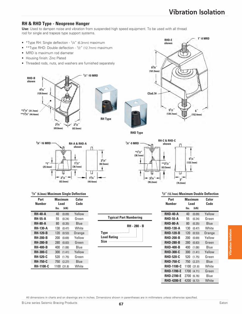
RH & RHD Type - Neoprene HangerUse: Used to dampen noise and vibration from suspended high speed equipment. To be used with all threadrod for single and trapeze type support systems.
• *Type RH: Single deflection - 1/4” (6.3mm) maximum• **Type RHD: Double deflection - 1/2” (12.7mm) maximum• MRD is maximum rod diameter • Housing finish: Zinc Plated • Threaded rods, nuts, and washers are furnished separately
Part Maximum ColorNumber Load Code
lbs. (kN)
RH-40-A 40 (0.09) YellowRH-55-A 55 (0.24) GreenRH-80-A 80 (0.35) BlueRH-130-A 130 (0.47) WhiteRH-120-B 120 (0.53) OrangeRH-200-B 200 (0.69) YellowRH-280-B 280 (0.83) GreenRH-400-B 400 (1.08) BlueRH-300-C 300 (1.41) YellowRH-520-C 520 (1.75) GreenRH-750-C 750 (2.27) BlueRH-1100-C 1100 (31.8) White
Typical Part Numbering
RH - 280 - B
TypeLoad RatingSize
1/4” (6.3mm) Maximum Single Deflection
Part Maximum ColorNumber Load Code
lbs. (kN)
RHD-40-A 40 (0.09) YellowRHD-55-A 55 (0.24) GreenRHD-80-A 80 (0.35) BlueRHD-130-A 130 (0.47) WhiteRHD-120-B 120 (0.53) OrangeRHD-200-B 200 (0.69) YellowRHD-280-B 280 (0.83) GreenRHD-400-B 400 (1.08) BlueRHD-300-C 300 (1.41) YellowRHD-520-C 520 (1.75) GreenRHD-750-C 750 (2.27) BlueRHD-1100-C 1100 (31.8) WhiteRHD-1700-E 1700 (4.71) GreenRHD-2700-E 2700 (6.76) BlueRHD-4200-E 4200 (8.72) White
1/2” (12.7mm) Maximum Double Deflection
1”-8 MRD
1/2”-10 MRD
3/8”-16 MRD 7/8”-9 MRD
63/8”(161.9mm)
6”(152.4mm)
51/2”(139.7mm)
C5x6.7#
RHD-Eshown
RHD-Bshown
RH Type
RHD Type
RH-A & RHD-Ashown
RH-C & RHD-Cshown
43/4”(120.6mm)
*11/4” (31.7mm)**13/4” (44.4mm)
21/2”(63.5mm)
23/4”(69.8mm)
*1”(25.4mm)
33/4”(95.2mm)
*11/2”(38.1mm)
**21/2”(63.5mm)
51/4”(133.1mm)
3”(76.2mm)
13/4”(44.4mm)
31/4”(82.5mm)
21/2”(63.5mm)
11/2”(38.1mm)
Vibration Isolation
68 B-Line series Seismic Bracing ProductsEaton
All dimensions in charts and on drawings are in inches. Dimensions shown in parentheses are in millimeters unless otherwise specified.
Vibration Isolation
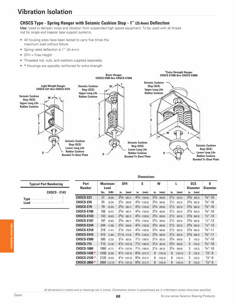
CHSCS Type - Spring Hanger with Seismic Cushion Stop - 1” (25.4mm) DeflectionUse: Used to dampen noise and vibration from suspended high speed equipment. To be used with all threadrod for single and trapeze type support systems.
• All housing sizes have been tested to carry five times themaximum load without failure
• Spring rated deflection is 1” (25.4mm)
• SFH = Free Height
• Threaded rod, nuts, and washers supplied separately
• * Housings are specially reinforced for extra strength
Dimensions
Part Maximum SFH S W L SCS DNumber Load Diameter Diameter
lbs. (kN) in. (mm) in. (mm) in. (mm) in. (mm) in. (mm)
CHSCS-E21 21 (0.09) 25/8 (66.7) 43/4 (120.6) 23/4 (69.8) 21/2 (63.5) 23/8 (60.3) 3/8”-16CHSCS-E55 55 (0.24) 23/4 (69.8) 43/4 (120.6) 23/4 (69.8) 21/2 (63.5) 23/8 (60.3) 3/8”-16CHSCS-E79 79 (0.35) 25/8 (66.7) 43/4 (120.6) 23/4 (69.8) 21/2 (63.5) 23/8 (60.3) 3/8”-16CHSCS-E106 106 (0.47) 25/8 (66.7) 43/4 (120.6) 23/4 (69.8) 21/2 (63.5) 23/8 (60.3) 3/8”-16CHSCS-E143 143 (0.63) 25/8 (66.7) 43/4 (120.6) 23/4 (69.8) 21/2 (63.5) 23/8 (60.3) 1/2”-13CHSCS-E187 187 (0.83) 25/8 (66.7) 43/4 (120.6) 23/4 (69.8) 21/2 (63.5) 23/8 (60.3) 1/2”-13CHSCS-E244 244 (1.08) 23/4 (69.8) 43/4 (120.6) 23/4 (69.8) 21/2 (63.5) 23/8 (60.3) 1/2”-13CHSCS-E318 318 (1.41) 31/8 (79.4) 43/4 (120.6) 23/4 (69.8) 21/2 (63.5) 23/8 (60.3) 5/8”-11CHSCS-E415 415 (1.84) 31/16 (77.8) 43/4 (120.6) 23/4 (69.8) 21/2 (63.5) 23/8 (60.3) 5/8”-11CHSCS-E500 500 (2.22) 31/4 (82.5) 71/2 (190.5) 31/4 (82.5) 23/4 (69.8) 3 (76.2) 3/4”-10CHSCS-715 715 (3.18) 41/4 (107.9) 71/2 (190.5) 31/4 (82.5) 23/4 (69.8) 3 (76.2) 3/4”-10CHSCS-1060 1060 (4.71) 41/4 (107.9) 71/2 (190.5) 31/4 (82.5) 23/4 (69.8) 3 (76.2) 3/4”-10CHSCS-1430 * 1430 (6.36) 41/4 (107.9) 83/8 (212.7) 6 (152.4) 6 (152.4) 3 (76.2) 7/8”-9CHSCS-2120 * 2120 (9.43) 41/4 (107.9) 83/8 (212.7) 6 (152.4) 6 (152.4) 3 (76.2) 7/8”-9CHSCS-2860 * 2860 (12.72) 41/4 (107.9) 83/8 (212.7) 6 (152.4) 6 (152.4) 3 (76.2) 7/8”-9
Typical Part Numbering
CHSCS - E143
TypeLoad
W
W
W L
L
L
S
S S
DDD
Seismic CushionStop (SCS)
Upper Long LifeRubber Cushion
Seismic CushionStop (SCS)
Upper Long LifeRubber CushionSeismic Cushion
Stop (SCS)Upper Long LifeRubber Cushion
Seismic CushionStop (SCS)
Lower Long LifeRubber Cushion
Bonded To Steel Plate
Seismic CushionStop (SCS)
Lower Long LifeRubber Cushion
Bonded To Steel Plate
Seismic CushionStop (SCS)
Lower Long LifeRubber Cushion
Bonded To Steel Plate
Basic HangerCHSCS-E500 thru CHSCS-E1060
Light Weight HangerCHSCS-E21 thru CHSCS-E415
*Extra Strength HangerCHSCS-E1580 thru CHSCS-E2860
All dimensions in charts and on drawings are in inches. Dimensions shown in parentheses are in millimeters unless otherwise specified.
Vibration Isolation
69B-Line series Seismic Bracing Products Eaton
Vibration Isolation
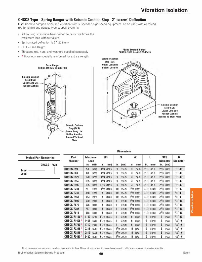
CHSCS Type - Spring Hanger with Seismic Cushion Stop - 2” (50.8mm) DeflectionUse: Used to dampen noise and vibration from suspended high speed equipment. To be used with all threadrod for single and trapeze type support systems.
• All housing sizes have been tested to carry five times themaximum load without failure
• Spring rated deflection is 2” (50.8mm)
• SFH = Free Height
• Threaded rod, nuts, and washers supplied separately
• * Housings are specially reinforced for extra strength
Dimensions
Part Maximum SFH S W L SCS DNumber Load Diameter Diameter
lbs. (kN) in. (mm) in. (mm) in. (mm) in. (mm) in. (mm)
CHSCS-F59 59 (0.26) 41/4 (107.9) 9 (228.6) 3 (76.2) 21/2 (63.5) 23/8 (60.3) 1/2”-13CHSCS-F83 83 (0.37) 41/4 (107.9) 9 (228.6) 3 (76.2) 21/2 (63.5) 23/8 (60.3) 1/2”-13CHSCS-F120 120 (0.53) 41/4 (107.9) 9 (228.6) 3 (76.2) 21/2 (63.5) 23/8 (60.3) 1/2”-13CHSCS-F155 155 (0.69) 41/4 (107.9) 9 (228.6) 3 (76.2) 21/2 (63.5) 23/8 (60.3) 1/2”-13CHSCS-F195 195 (0.87) 49/16 (115.9) 9 (228.6) 3 (76.2) 21/2 (63.5) 23/8 (60.3) 1/2”-13CHSCS-F241 241 (1.07) 41/2 (114.3) 10 (254.0) 51/2 (139.7) 41/2 (114.3) 23/8 (60.3) 1/2”-13CHSCS-F348 348 (1.55) 5 (127.0) 10 (254.0) 51/2 (139.7) 41/2 (114.3) 23/8 (60.3) 5/8”-11CHSCS-F453 453 (2.01) 5 (127.0) 10 (254.0) 51/2 (139.7) 41/2 (114.3) 23/8 (60.3) 5/8”-11CHSCS-F590 590 (2.62) 5 (127.0) 11 (279.4) 51/4 (133.3) 41/2 (114.3) 23/8 (60.3) 3/4”-10CHSCS-F676 676 (3.00) 5 (127.0) 11 (279.4) 51/4 (133.3) 41/2 (114.3) 23/8 (60.3) 3/4”-10CHSCS-F787 787 (3.50) 5 (127.0) 11 (279.4) 51/4 (133.3) 41/2 (114.3) 23/8 (60.3) 3/4”-10CHSCS-F918 918 (4.08) 5 (127.0) 11 (279.4) 51/4 (133.3) 41/2 (114.3) 23/8 (60.3) 3/4”-10CHSCS-F1159 * 1159 (5.15) 67/16 (163.5) 11 (279.4) 6 (152.9) 5 (127.0) 3 (76.2) 3/4”-10CHSCS-F1408 * 1408 (6.26) 67/16 (163.5) 11 (279.4) 6 (152.9) 5 (127.0) 3 (76.2) 7/8”-9CHSCS-F1710 * 1710 (7.60) 67/16 (163.5) 11 (279.4) 6 (152.9) 5 (127.0) 3 (76.2) 7/8”-9CHSCS-F2318 * 2318 (10.31) 67/16 (163.5) 111/4 (285.7) 11 (279.4) 5 (127.0) 3 (76.2) 7/8”-9CHSCS-F2816 * 2816 (12.52) 67/16 (163.5) 111/4 (285.7) 11 (279.4) 5 (127.0) 3 (76.2) 7/8”-9CHSCS-F3420 * 3420 (15.21) 67/16 (163.5) 111/4 (285.7) 11 (279.4) 5 (127.0) 3 (76.2) 7/8”-9
Typical Part Numbering
CHSCS - F120
TypeLoad
W
W
L
L
S
S
D
D
Seismic CushionStop (SCS)
Upper Long LifeRubber Cushion
Seismic CushionStop (SCS)
Upper Long LifeRubber Cushion
Seismic CushionStop (SCS)
Lower Long LifeRubber CushionBonded To Steel
Plate
Seismic CushionStop (SCS)
Lower Long LifeRubber Cushion
Bonded To Steel Plate
Basic HangerCHSCS-F59 thru CHSCS-F918
*Extra Strength HangerCHSCS-F1159 thru CHSCS-F3420
Vibration Isolation
70 B-Line series Seismic Bracing ProductsEaton
All dimensions in charts and on drawings are in inches. Dimensions shown in parentheses are in millimeters unless otherwise specified.
Vibration Isolation
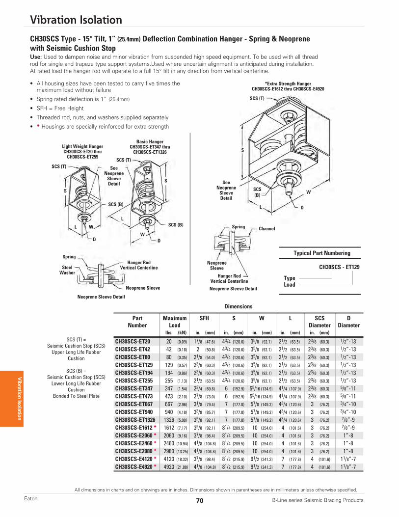
CH30SCS Type - 15° Tilt, 1” (25.4mm) Deflection Combination Hanger - Spring & Neoprenewith Seismic Cushion StopUse: Used to dampen noise and minor vibration from suspended high speed equipment. To be used with all threadrod for single and trapeze type support systems.Used where uncertain alignment is anticipated during installation. At rated load the hanger rod will operate to a full 15° tilt in any direction from vertical centerline.
• All housing sizes have been tested to carry five times themaximum load without failure
• Spring rated deflection is 1” (25.4mm)
• SFH = Free Height
• Threaded rod, nuts, and washers supplied separately
• * Housings are specially reinforced for extra strength
Dimensions
Part Maximum SFH S W L SCS DNumber Load Diameter Diameter
lbs. (kN) in. (mm) in. (mm) in. (mm) in. (mm) in. (mm)
CH30SCS-ET20 20 (0.09) 17/8 (47.6) 43/4 (120.6) 35/8 (92.1) 21/2 (63.5) 23/8 (60.3) 1/2”-13CH30SCS-ET42 42 (0.18) 2 (50.8) 43/4 (120.6) 35/8 (92.1) 21/2 (63.5) 23/8 (60.3) 1/2”-13CH30SCS-ET80 80 (0.35) 21/8 (54.0) 43/4 (120.6) 35/8 (92.1) 21/2 (63.5) 23/8 (60.3) 1/2”-13CH30SCS-ET129 129 (0.57) 23/8 (60.3) 43/4 (120.6) 35/8 (92.1) 21/2 (63.5) 23/8 (60.3) 1/2”-13CH30SCS-ET194 194 (0.86) 23/8 (60.3) 43/4 (120.6) 35/8 (92.1) 21/2 (63.5) 23/8 (60.3) 1/2”-13CH30SCS-ET255 255 (1.13) 21/2 (63.5) 43/4 (120.6) 35/8 (92.1) 21/2 (63.5) 23/8 (60.3) 1/2”-13CH30SCS-ET347 347 (1.54) 23/4 (69.8) 6 (152.9) 55/16 (134.9) 41/4 (107.9) 23/8 (60.3) 5/8”-11CH30SCS-ET473 473 (2.10) 27/8 (73.0) 6 (152.9) 55/16 (134.9) 41/4 (107.9) 23/8 (60.3) 5/8”-11CH30SCS-ET667 667 (2.96) 31/8 (79.4) 7 (177.8) 57/8 (149.2) 43/4 (120.6) 3 (76.2) 3/4”-10CH30SCS-ET940 940 (4.18) 33/8 (85.7) 7 (177.8) 57/8 (149.2) 43/4 (120.6) 3 (76.2) 3/4”-10CH30SCS-ET1326 1326 (5.90) 35/8 (92.1) 7 (177.8) 57/8 (149.2) 43/4 (120.6) 3 (76.2) 7/8”-9CH30SCS-E1612 * 1612 (7.17) 35/8 (92.1) 81/4 (209.5) 10 (254.0) 4 (101.6) 3 (76.2) 7/8”-9CH30SCS-E2060 * 2060 (9.16) 37/8 (98.4) 81/4 (209.5) 10 (254.0) 4 (101.6) 3 (76.2) 1”-8CH30SCS-E2460 * 2460 (10.94) 41/8 (104.8) 81/4 (209.5) 10 (254.0) 4 (101.6) 3 (76.2) 1”-8CH30SCS-E2980 * 2980 (13.25) 41/8 (104.8) 81/4 (209.5) 10 (254.0) 4 (101.6) 3 (76.2) 1”-8CH30SCS-E4120 * 4120 (18.32) 37/8 (98.4) 81/2 (215.9) 91/2 (241.3) 7 (177.8) 4 (101.6) 11/8”-7CH30SCS-E4920 * 4920 (21.88) 41/8 (104.8) 81/2 (215.9) 91/2 (241.3) 7 (177.8) 4 (101.6) 11/8”-7
Typical Part Numbering
CH30SCS - ET129
TypeLoad
W
W
L
L
S
S
D
D
SeeNeopreneSleeveDetail See
NeopreneSleeveDetail
SCS (T)
SCS (T)
SCS (T)
SCS (B)
W
L
D
SCS (B)
SCS(B)
SCS (T) =Seismic Cushion Stop (SCS)Upper Long Life Rubber
Cushion
SCS (B) =Seismic Cushion Stop (SCS)Lower Long Life Rubber
CushionBonded To Steel Plate
Light Weight HangerCH30SCS-ET20 thruCH30SCS-ET255
Basic HangerCH30SCS-ET347 thru CH30SCS-ET1326
Spring
SteelWasher
Neoprene Sleeve
Neoprene Sleeve Detail
NeopreneSleeve
Hanger RodVertical Centerline
Hanger RodVertical Centerline
Spring Channel
Neoprene Sleeve Detail
*Extra Strength HangerCH30SCS-E1612 thru CH30SCS-E4920
S
All dimensions in charts and on drawings are in inches. Dimensions shown in parentheses are in millimeters unless otherwise specified.
Vibration Isolation
71B-Line series Seismic Bracing Products Eaton
Vibration Isolation
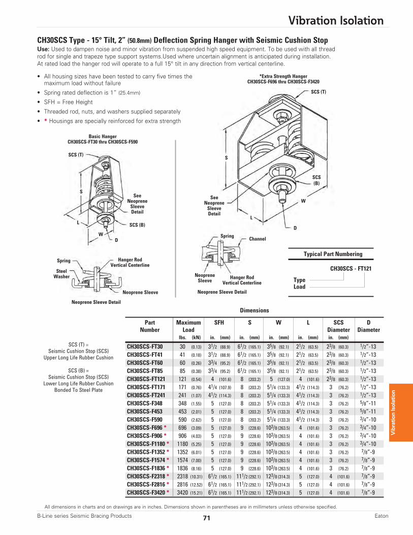
CH30SCS Type - 15° Tilt, 2” (50.8mm) Deflection Spring Hanger with Seismic Cushion StopUse: Used to dampen noise and minor vibration from suspended high speed equipment. To be used with all threadrod for single and trapeze type support systems.Used where uncertain alignment is anticipated during installation. At rated load the hanger rod will operate to a full 15° tilt in any direction from vertical centerline.
• All housing sizes have been tested to carry five times themaximum load without failure
• Spring rated deflection is 1” (25.4mm)
• SFH = Free Height
• Threaded rod, nuts, and washers supplied separately
• * Housings are specially reinforced for extra strength
Dimensions
Part Maximum SFH S W L SCS DNumber Load Diameter Diameter
lbs. (kN) in. (mm) in. (mm) in. (mm) in. (mm) in. (mm)
CH30SCS-FT30 30 (0.13) 31/2 (88.9) 61/2 (165.1) 35/8 (92.1) 21/2 (63.5) 23/8 (60.3) 1/2”-13CH30SCS-FT41 41 (0.18) 31/2 (88.9) 61/2 (165.1) 35/8 (92.1) 21/2 (63.5) 23/8 (60.3) 1/2”-13CH30SCS-FT60 60 (0.26) 33/4 (95.2) 61/2 (165.1) 35/8 (92.1) 21/2 (63.5) 23/8 (60.3) 1/2”-13CH30SCS-FT85 85 (0.38) 33/4 (95.2) 61/2 (165.1) 35/8 (92.1) 21/2 (63.5) 23/8 (60.3) 1/2”-13CH30SCS-FT121 121 (0.54) 4 (101.6) 8 (203.2) 5 (127.0) 4 (101.6) 23/8 (60.3) 1/2”-13CH30SCS-FT171 171 (0.76) 41/4 (107.9) 8 (203.2) 51/4 (133.3) 41/2 (114.3) 3 (76.2) 1/2”-13CH30SCS-FT241 241 (1.07) 41/2 (114.3) 8 (203.2) 51/4 (133.3) 41/2 (114.3) 3 (76.2) 1/2”-13CH30SCS-F348 348 (1.55) 5 (127.0) 8 (203.2) 51/4 (133.3) 41/2 (114.3) 3 (76.2) 5/8”-11CH30SCS-F453 453 (2.01) 5 (127.0) 8 (203.2) 51/4 (133.3) 41/2 (114.3) 3 (76.2) 5/8”-11CH30SCS-F590 590 (2.62) 5 (127.0) 8 (203.2) 51/4 (133.3) 41/2 (114.3) 3 (76.2) 3/4”-10CH30SCS-F696 * 696 (3.09) 5 (127.0) 9 (228.6) 103/8 (263.5) 4 (101.6) 3 (76.2) 3/4”-10CH30SCS-F906 * 906 (4.03) 5 (127.0) 9 (228.6) 103/8 (263.5) 4 (101.6) 3 (76.2) 3/4”-10CH30SCS-F1180 * 1180 (5.25) 5 (127.0) 9 (228.6) 103/8 (263.5) 4 (101.6) 3 (76.2) 3/4”-10CH30SCS-F1352 * 1352 (6.01) 5 (127.0) 9 (228.6) 103/8 (263.5) 4 (101.6) 3 (76.2) 7/8”-9CH30SCS-F1574 * 1574 (7.00) 5 (127.0) 9 (228.6) 103/8 (263.5) 4 (101.6) 3 (76.2) 7/8”-9CH30SCS-F1836 * 1836 (8.16) 5 (127.0) 9 (228.6) 103/8 (263.5) 4 (101.6) 3 (76.2) 7/8”-9CH30SCS-F2318 * 2318 (10.31) 61/2 (165.1) 111/2 (292.1) 123/8 (314.3) 5 (127.0) 4 (101.6) 7/8”-9CH30SCS-F2816 * 2816 (12.52) 61/2 (165.1) 111/2 (292.1) 123/8 (314.3) 5 (127.0) 4 (101.6) 7/8”-9CH30SCS-F3420 * 3420 (15.21) 61/2 (165.1) 111/2 (292.1) 123/8 (314.3) 5 (127.0) 4 (101.6) 7/8”-9
Typical Part Numbering
CH30SCS - FT121
TypeLoad
W
L
D
SeeNeopreneSleeveDetail
SeeNeopreneSleeveDetail
SCS (T)
SCS (T)
W
L
S
D
SCS (B)
SCS(B)
Basic HangerCH30SCS-FT30 thru CH30SCS-F590
Spring
SteelWasher
Neoprene Sleeve
Neoprene Sleeve Detail
NeopreneSleeve
Hanger RodVertical Centerline
Hanger RodVertical Centerline
Spring Channel
Neoprene Sleeve Detail
*Extra Strength HangerCH30SCS-F696 thru CH30SCS-F3420
S
SCS (T) =Seismic Cushion Stop (SCS)
Upper Long Life Rubber Cushion
SCS (B) =Seismic Cushion Stop (SCS)
Lower Long Life Rubber CushionBonded To Steel Plate
Vibration Isolation
72 B-Line series Seismic Bracing ProductsEaton
All dimensions in charts and on drawings are in inches. Dimensions shown in parentheses are in millimeters unless otherwise specified.
Vibration Isolation
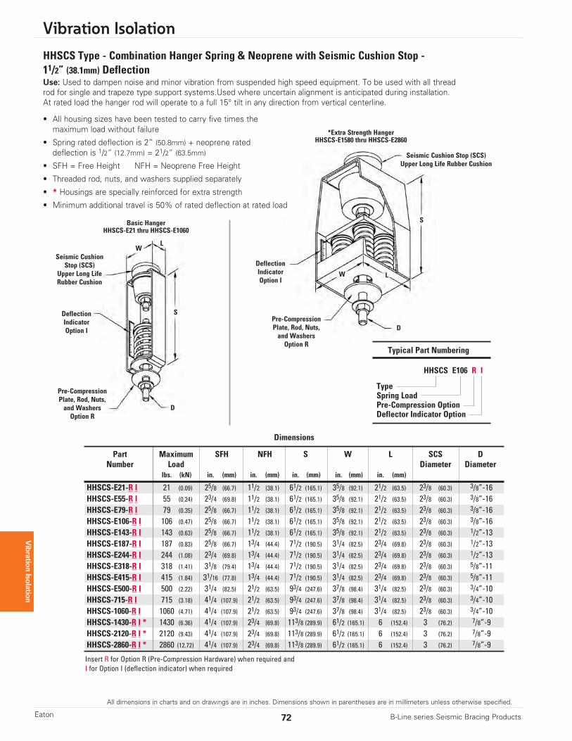
HHSCS Type - Combination Hanger Spring & Neoprene with Seismic Cushion Stop - 11/2” (38.1mm) DeflectionUse: Used to dampen noise and minor vibration from suspended high speed equipment. To be used with all threadrod for single and trapeze type support systems.Used where uncertain alignment is anticipated during installation. At rated load the hanger rod will operate to a full 15° tilt in any direction from vertical centerline.
Dimensions
Part Maximum SFH NFH S W L SCS DNumber Load Diameter Diameter
lbs. (kN) in. (mm) in. (mm) in. (mm) in. (mm) in. (mm)
HHSCS-E21-R I 21 (0.09) 25/8 (66.7) 11/2 (38.1) 61/2 (165.1) 35/8 (92.1) 21/2 (63.5) 23/8 (60.3) 3/8”-16HHSCS-E55-R I 55 (0.24) 23/4 (69.8) 11/2 (38.1) 61/2 (165.1) 35/8 (92.1) 21/2 (63.5) 23/8 (60.3) 3/8”-16HHSCS-E79-R I 79 (0.35) 25/8 (66.7) 11/2 (38.1) 61/2 (165.1) 35/8 (92.1) 21/2 (63.5) 23/8 (60.3) 3/8”-16HHSCS-E106-R I 106 (0.47) 25/8 (66.7) 11/2 (38.1) 61/2 (165.1) 35/8 (92.1) 21/2 (63.5) 23/8 (60.3) 3/8”-16HHSCS-E143-R I 143 (0.63) 25/8 (66.7) 11/2 (38.1) 61/2 (165.1) 35/8 (92.1) 21/2 (63.5) 23/8 (60.3) 1/2”-13HHSCS-E187-R I 187 (0.83) 25/8 (66.7) 13/4 (44.4) 71/2 (190.5) 31/4 (82.5) 23/4 (69.8) 23/8 (60.3) 1/2”-13HHSCS-E244-R I 244 (1.08) 23/4 (69.8) 13/4 (44.4) 71/2 (190.5) 31/4 (82.5) 23/4 (69.8) 23/8 (60.3) 1/2”-13HHSCS-E318-R I 318 (1.41) 31/8 (79.4) 13/4 (44.4) 71/2 (190.5) 31/4 (82.5) 23/4 (69.8) 23/8 (60.3) 5/8”-11HHSCS-E415-R I 415 (1.84) 31/16 (77.8) 13/4 (44.4) 71/2 (190.5) 31/4 (82.5) 23/4 (69.8) 23/8 (60.3) 5/8”-11HHSCS-E500-R I 500 (2.22) 31/4 (82.5) 21/2 (63.5) 93/4 (247.6) 37/8 (98.4) 31/4 (82.5) 23/8 (60.3) 3/4”-10HHSCS-715-R I 715 (3.18) 41/4 (107.9) 21/2 (63.5) 93/4 (247.6) 37/8 (98.4) 31/4 (82.5) 23/8 (60.3) 3/4”-10HHSCS-1060-R I 1060 (4.71) 41/4 (107.9) 21/2 (63.5) 93/4 (247.6) 37/8 (98.4) 31/4 (82.5) 23/8 (60.3) 3/4”-10HHSCS-1430-R I * 1430 (6.36) 41/4 (107.9) 23/4 (69.8) 113/8 (289.9) 61/2 (165.1) 6 (152.4) 3 (76.2) 7/8”-9HHSCS-2120-R I * 2120 (9.43) 41/4 (107.9) 23/4 (69.8) 113/8 (289.9) 61/2 (165.1) 6 (152.4) 3 (76.2) 7/8”-9HHSCS-2860-R I * 2860 (12.72) 41/4 (107.9) 23/4 (69.8) 113/8 (289.9) 61/2 (165.1) 6 (152.4) 3 (76.2) 7/8”-9
Insert R for Option R (Pre-Compression Hardware) when required andI for Option I (deflection indicator) when required
W
W L
L
S
S
D
D
DeflectionIndicatorOption I
DeflectionIndicatorOption I
Seismic Cushion Stop (SCS)Upper Long Life Rubber Cushion
Seismic CushionStop (SCS)
Upper Long LifeRubber Cushion
Basic HangerHHSCS-E21 thru HHSCS-E1060
*Extra Strength HangerHHSCS-E1580 thru HHSCS-E2860
Typical Part Numbering
HHSCS E106 R I
TypeSpring LoadPre-Compression OptionDeflector Indicator Option
Pre-CompressionPlate, Rod, Nuts,and WashersOption R
Pre-CompressionPlate, Rod, Nuts,and WashersOption R
• All housing sizes have been tested to carry five times themaximum load without failure
• Spring rated deflection is 2” (50.8mm) + neoprene rateddeflection is 1/2” (12.7mm) = 21/2” (63.5mm)
• SFH = Free Height NFH = Neoprene Free Height
• Threaded rod, nuts, and washers supplied separately
• * Housings are specially reinforced for extra strength
• Minimum additional travel is 50% of rated deflection at rated load
All dimensions in charts and on drawings are in inches. Dimensions shown in parentheses are in millimeters unless otherwise specified.
Vibration Isolation
73B-Line series Seismic Bracing Products Eaton
Vibration Isolation
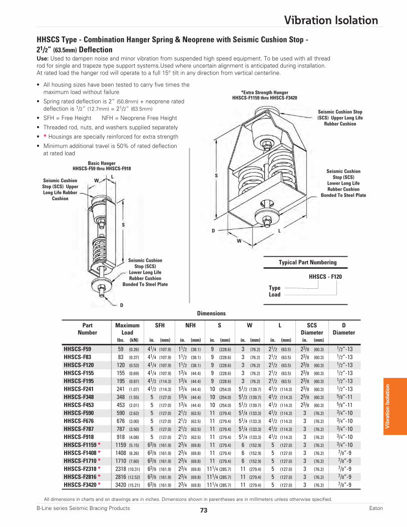
HHSCS Type - Combination Hanger Spring & Neoprene with Seismic Cushion Stop - 21/2” (63.5mm) DeflectionUse: Used to dampen noise and minor vibration from suspended high speed equipment. To be used with all threadrod for single and trapeze type support systems.Used where uncertain alignment is anticipated during installation. At rated load the hanger rod will operate to a full 15° tilt in any direction from vertical centerline.
• All housing sizes have been tested to carry five times themaximum load without failure
• Spring rated deflection is 2” (50.8mm) + neoprene rateddeflection is 1/2” (12.7mm) = 21/2” (63.5mm)
• SFH = Free Height NFH = Neoprene Free Height
• Threaded rod, nuts, and washers supplied separately
• * Housings are specially reinforced for extra strength
• Minimum additional travel is 50% of rated deflectionat rated load
Typical Part Numbering
HHSCS - F120
TypeLoad
W
W
L
L
S
S
D
D
Seismic Cushion Stop(SCS) Upper Long Life
Rubber Cushion
Seismic CushionStop (SCS) UpperLong Life Rubber
Cushion
Seismic CushionStop (SCS)
Lower Long LifeRubber Cushion
Bonded To Steel Plate
Seismic CushionStop (SCS)
Lower Long LifeRubber Cushion
Bonded To Steel Plate
Basic HangerHHSCS-F59 thru HHSCS-F918
*Extra Strength HangerHHSCS-F1159 thru HHSCS-F3420
Dimensions
Part Maximum SFH NFH S W L SCS DNumber Load Diameter Diameter
lbs. (kN) in. (mm) in. (mm) in. (mm) in. (mm) in. (mm) in. (mm)
HHSCS-F59 59 (0.26) 41/4 (107.9) 11/2 (38.1) 9 (228.6) 3 (76.2) 21/2 (63.5) 23/8 (60.3) 1/2”-13HHSCS-F83 83 (0.37) 41/4 (107.9) 11/2 (38.1) 9 (228.6) 3 (76.2) 21/2 (63.5) 23/8 (60.3) 1/2”-13HHSCS-F120 120 (0.53) 41/4 (107.9) 11/2 (38.1) 9 (228.6) 3 (76.2) 21/2 (63.5) 23/8 (60.3) 1/2”-13HHSCS-F155 155 (0.69) 41/4 (107.9) 13/4 (44.4) 9 (228.6) 3 (76.2) 21/2 (63.5) 23/8 (60.3) 1/2”-13HHSCS-F195 195 (0.87) 41/2 (114.3) 13/4 (44.4) 9 (228.6) 3 (76.2) 21/2 (63.5) 23/8 (60.3) 1/2”-13HHSCS-F241 241 (1.07) 41/2 (114.3) 13/4 (44.4) 10 (254.0) 51/2 (139.7) 41/2 (114.3) 23/8 (60.3) 1/2”-13HHSCS-F348 348 (1.55) 5 (127.0) 13/4 (44.4) 10 (254.0) 51/2 (139.7) 41/2 (114.3) 23/8 (60.3) 5/8”-11HHSCS-F453 453 (2.01) 5 (127.0) 13/4 (44.4) 10 (254.0) 51/2 (139.7) 41/2 (114.3) 23/8 (60.3) 5/8”-11HHSCS-F590 590 (2.62) 5 (127.0) 21/2 (63.5) 11 (279.4) 51/4 (133.3) 41/2 (114.3) 3 (76.2) 3/4”-10HHSCS-F676 676 (3.00) 5 (127.0) 21/2 (63.5) 11 (279.4) 51/4 (133.3) 41/2 (114.3) 3 (76.2) 3/4”-10HHSCS-F787 787 (3.50) 5 (127.0) 21/2 (63.5) 11 (279.4) 51/4 (133.3) 41/2 (114.3) 3 (76.2) 3/4”-10HHSCS-F918 918 (4.08) 5 (127.0) 21/2 (63.5) 11 (279.4) 51/4 (133.3) 41/2 (114.3) 3 (76.2) 3/4”-10HHSCS-F1159 * 1159 (5.15) 63/8 (161.9) 23/4 (69.8) 11 (279.4) 6 (152.9) 5 (127.0) 3 (76.2) 3/4”-10HHSCS-F1408 * 1408 (6.26) 63/8 (161.9) 23/4 (69.8) 11 (279.4) 6 (152.9) 5 (127.0) 3 (76.2) 7/8”-9HHSCS-F1710 * 1710 (7.60) 63/8 (161.9) 23/4 (69.8) 11 (279.4) 6 (152.9) 5 (127.0) 3 (76.2) 7/8”-9HHSCS-F2318 * 2318 (10.31) 63/8 (161.9) 23/4 (69.8) 111/4 (285.7) 11 (279.4) 5 (127.0) 3 (76.2) 7/8”-9HHSCS-F2816 * 2816 (12.52) 63/8 (161.9) 23/4 (69.8) 111/4 (285.7) 11 (279.4) 5 (127.0) 3 (76.2) 7/8”-9HHSCS-F3420 * 3420 (15.21) 63/8 (161.9) 23/4 (69.8) 111/4 (285.7) 11 (279.4) 5 (127.0) 3 (76.2) 7/8”-9

Vibration Isolation
74 B-Line series Seismic Bracing ProductsEaton
All dimensions in charts and on drawings are in inches. Dimensions shown in parentheses are in millimeters unless otherwise specified.
Vibration Isolation
HH30SCS Type - 15° Tilt, 11/2” (38.1mm) Deflection Combination Hanger - Spring & Neoprenewith Seismic Cushion StopUse: Used to dampen noise and minor vibration from suspended high speed equipment. To be used with all threadrod for single and trapeze type support systems.Used where uncertain alignment is anticipated during installation. At rated load the hanger rod will operate to a full 15° tilt in any direction from vertical centerline.
• All housing sizes have been tested to carry five times themaximum load without failure
• Spring rated deflection is 1” (25.4mm) + neoprene rateddeflection is 1/2” (12.7mm) = 11/2” (38.1mm)
• SFH = Free Height NFH = Neoprene Free Height
• Threaded rod, nuts, and washers supplied separately
• * Housings are specially reinforced for extra strength
• Minimum additional travel is 50% of rated deflection at rated load
Dimensions
Part Maximum SFH NFH S W L SCS DNumber Load Diameter Diameter
lbs. (kN) in. (mm) in. (mm) in. (mm) in. (mm) in. (mm) in. (mm)
HH30SCS-ET20 20 (0.09) 17/8 (47.6) 11/2 (38.1) 61/2 (165.1) 35/8 (92.1) 21/2 (63.5) 23/8 (60.3) 3/8”-16HH30SCS-ET42 42 (0.18) 2 (50.8) 11/2 (38.1) 61/2 (165.1) 35/8 (92.1) 21/2 (63.5) 23/8 (60.3) 3/8”-16HH30SCS-ET80 80 (0.35) 21/8 (54.0) 11/2 (38.1) 61/2 (165.1) 35/8 (92.1) 21/2 (63.5) 23/8 (60.3) 3/8”-16HH30SCS-ET129 129 (0.57) 23/8 (60.3) 11/2 (38.1) 61/2 (165.1) 35/8 (92.1) 21/2 (63.5) 23/8 (60.3) 3/8”-16HH30SCS-ET194 194 (0.86) 23/8 (60.3) 13/4 (44.4) 71/2 (190.5) 4 (101.6) 3 (76.2) 23/8 (60.3) 1/2”-13HH30SCS-ET255 255 (1.13) 21/2 (63.5) 13/4 (44.4) 71/2 (190.5) 4 (101.6) 3 (76.2) 23/8 (60.3) 1/2”-13HH30SCS-ET347 347 (1.54) 23/4 (69.8) 13/4 (44.4) 81/2 (215.9) 55/16 (134.9) 41/4 (107.9) 23/8 (60.3) 5/8”-11HH30SCS-ET473 473 (2.10) 27/8 (73.0) 21/2 (63.5) 81/2 (215.9) 55/16 (134.9) 41/4 (107.9) 23/8 (60.3) 5/8”-11HH30SCS-ET667 667 (2.96) 31/8 (79.4) 21/2 (63.5) 10 (254.0) 57/8 (149.2) 43/4 (120.6) 3 (76.2) 3/4”-10HH30SCS-ET940 940 (4.18) 33/8 (85.7) 21/2 (63.5) 10 (254.0) 57/8 (149.2) 43/4 (120.6) 3 (76.2) 3/4”-10HH30SCS-ET1326 1326 (5.90) 35/8 (92.1) 23/4 (69.8) 10 (254.0) 57/8 (149.2) 43/4 (120.6) 3 (76.2) 7/8”-9HH30SCS-E1612 * 1612 (7.17) 35/8 (92.1) 23/4 (69.8) 111/4 (285.7) 10 (254.0) 4 (101.6) 3 (76.2) 7/8”-9HH30SCS-E2060 * 2060 (9.16) 37/8 (98.4) 23/4 (69.8) 111/4 (285.7) 10 (254.0) 4 (101.6) 3 (76.2) 1”-8HH30SCS-E2460 * 2460 (10.94) 41/8 (104.8) 23/4 (69.8) 111/4 (285.7) 10 (254.0) 4 (101.6) 3 (76.2) 1”-8HH30SCS-E2980 * 2980 (13.25) 41/8 (104.8) 23/4 (69.8) 111/4 (285.7) 10 (254.0) 4 (101.6) 3 (76.2) 1”-8HH30SCS-E4120 * 4120 (18.32) 37/8 (98.4) 23/4 (69.8) 12 (304.8) 91/2 (241.3) 7 (177.8) 4 (101.6) 1”-8HH30SCS-E4920 * 4920 (21.88) 41/8 (104.8) 23/4 (69.8) 12 (304.8) 91/2 (241.3) 7 (177.8) 4 (101.6) 1”-8
Typical Part Numbering
HH30SCS - ET129
TypeLoad
W
LL
S
S
D
SeeNeopreneSleeveDetail
SeeNeopreneSleeveDetail
SCS (T)
SCS (T)
W
D
SCS (B)
SCS(B)
SCS (T) = SeismicCushion Stop (SCS)Upper Long LifeRubber Cushion
SCS (B) = SeismicCushion Stop (SCS)Lower Long LifeRubber CushionBonded ToSteel Plate
Basic HangerHH30SCS-ET20 thru HH30SCS-ET1326
Spring
SteelWasher
Neoprene Sleeve
Neoprene
Neoprene
Neoprene Sleeve Detail
NeopreneSleeve
Hanger RodVertical Centerline
Hanger RodVertical Centerline
Spring Channel
Neoprene Sleeve Detail
* Extra Strength HangerHH30SCS-E1612 thru HH30SCS-E4920
All dimensions in charts and on drawings are in inches. Dimensions shown in parentheses are in millimeters unless otherwise specified.
Vibration Isolation
75B-Line series Seismic Bracing Products Eaton
Vibration Isolation
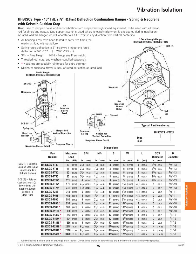
HH30SCS Type - 15° Tilt, 21/2” (63.5mm) Deflection Combination Hanger - Spring & Neoprenewith Seismic Cushion StopUse: Used to dampen noise and minor vibration from suspended high speed equipment. To be used with all threadrod for single and trapeze type support systems.Used where uncertain alignment is anticipated during installation. At rated load the hanger rod will operate to a full 15° tilt in any direction from vertical centerline.
• All housing sizes have been tested to carry five times themaximum load without failure
• Spring rated deflection is 2” (50.8mm) + neoprene rateddeflection is 1/2” (12.7mm) = 21/2” (63.5mm)
• SFH = Free Height NFH = Neoprene Free Height • Threaded rod, nuts, and washers supplied separately• * Housings are specially reinforced for extra strength• Minimum additional travel is 50% of rated deflection at rated load
Dimensions
Part Maximum SFH NFH S W L SCS DNumber Load Diameter Diameter
lbs. (kN) in. (mm) in. (mm) in. (mm) in. (mm) in. (mm) in. (mm)
HH30SCS-FT30 30 (0.13) 31/2 (88.9) 11/2 (38.1) 8 (203.2) 5 (127.0) 4 (101.6) 23/8 (63.5) 1/2”-13HH30SCS-FT41 41 (0.18) 31/2 (88.9) 11/2 (38.1) 8 (203.2) 5 (127.0) 4 (101.6) 23/8 (63.5) 1/2”-13HH30SCS-FT60 60 (0.26) 33/4 (95.2) 11/2 (38.1) 8 (203.2) 5 (127.0) 4 (101.6) 23/8 (63.5) 1/2”-13HH30SCS-FT85 85 (0.38) 33/4 (95.2) 11/2 (38.1) 8 (203.2) 5 (127.0) 4 (101.6) 23/8 (63.5) 1/2”-13HH30SCS-FT121 121 (0.54) 4 (101.6) 11/2 (38.1) 8 (203.2) 5 (127.0) 4 (101.6) 23/8 (63.5) 1/2”-13HH30SCS-FT171 171 (0.76) 41/4 (107.9) 13/4 (44.4) 10 (254.0) 51/4 (133.3) 41/2 (114.3) 3 (76.2) 1/2”-13HH30SCS-FT241 241 (1.07) 41/2 (114.3) 13/4 (44.4) 10 (254.0) 51/4 (133.3) 41/2 (114.3) 3 (76.2) 1/2”-13HH30SCS-F348 348 (1.55) 5 (127.0) 13/4 (44.4) 10 (254.0) 51/4 (133.3) 41/2 (114.3) 3 (76.2) 5/8”-11HH30SCS-F453 453 (2.01) 5 (127.0) 13/4 (44.4) 11 (279.4) 51/4 (133.3) 41/2 (114.3) 3 (76.2) 5/8”-11HH30SCS-F590 590 (2.62) 5 (127.0) 21/2 (63.5) 11 (279.4) 51/4 (133.3) 41/2 (114.3) 3 (76.2) 3/4”-10HH30SCS-F696 * 696 (3.09) 5 (127.0) 21/2 (63.5) 11 (279.4) 103/8 (263.5) 4 (101.6) 3 (76.2) 3/4”-10HH30SCS-F906 * 906 (4.03) 5 (127.0) 21/2 (63.5) 12 (304.8) 103/8 (263.5) 4 (101.6) 3 (76.2) 3/4”-10HH30SCS-F1180 * 1180 (5.25) 5 (127.0) 21/2 (63.5) 12 (304.8) 103/8 (263.5) 4 (101.6) 3 (76.2) 3/4”-10HH30SCS-F1352 * 1352 (6.01) 5 (127.0) 23/4 (69.8) 12 (304.8) 103/8 (263.5) 4 (101.6) 3 (76.2) 7/8”-9HH30SCS-F1574 * 1574 (7.00) 5 (127.0) 23/4 (69.8) 12 (304.8) 103/8 (263.5) 4 (101.6) 3 (76.2) 7/8”-9HH30SCS-F1836 * 1836 (8.16) 5 (127.0) 23/4 (69.8) 12 (304.8) 103/8 (263.5) 4 (101.6) 3 (76.2) 7/8”-9HH30SCS-F2318 * 2318 (10.31) 61/2 (165.1) 23/4 (69.8) 141/4 (361.9) 123/8 (314.3) 5 (127.0) 4 (101.6) 7/8”-9HH30SCS-F2816 * 2816 (12.52) 61/2 (165.1) 23/4 (69.8) 141/4 (361.9) 123/8 (314.3) 5 (127.0) 4 (101.6) 7/8”-9HH30SCS-F3420 * 3420 (15.21) 61/2 (165.1) 23/4 (69.8) 141/4 (361.9) 123/8 (314.3) 5 (127.0) 4 (101.6) 7/8”-9
Typical Part Numbering
HH30SCS - FT121
TypeLoad
W
LL
S
D
SeeNeopreneSleeveDetail
SeeNeopreneSleeveDetail
SCS (T)
SCS (T)
W
D
SCS (B)
SCS(B)
SCS (T) = SeismicCushion Stop (SCS)Upper Long LifeRubber Cushion
SCS (B) = SeismicCushion Stop (SCS)Lower Long LifeRubber CushionBonded ToSteel Plate
Basic HangerHH30SCS-FT30 thru HH30SCS-F590
Spring
SteelWasher
Neoprene Sleeve
Neoprene
Neoprene
Neoprene Sleeve Detail
NeopreneSleeve Hanger Rod
Vertical Centerline
Hanger RodVertical Centerline
Spring Channel
Neoprene Sleeve Detail
* Extra Strength HangerHH30SCS-F696 thru HH30SCS-F3420
S
Vibration Isolation
76 B-Line series Seismic Bracing ProductsEaton
All dimensions in charts and on drawings are in inches. Dimensions shown in parentheses are in millimeters unless otherwise specified.
Vibration Isolation
B-LINE
B-LINE
BVP150
BVP150
1 1/2”
I.P
1 1/2” I.P..
C
A
B
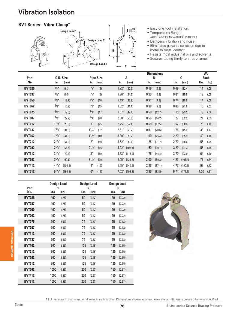
BVT Series - Vibra-Clamp™
• Easy one tool installation.• Temperature Range:-40°F (-40°C) to +300°F (148.9°C)
• Dampens vibration and noise.• Eliminates galvanic corrosion due to metal to metal contact.
• Resists most industrial oils and solvents.• Secures tubing firmly to strut channel.
Design Load 2
Design Load 1
Design Load 3
Dimensions Wt.Part O.D. Size Pipe Size A B C EachNo. in. (mm) in. (mm) in. (mm) in. (mm) in. (mm) Lbs. (kg)
BVT025 1/4" (6.3) 1/8" (3) 1.22" (30.9) 0.19" (4.8) 0.49" (12.4) .11 (.05)
BVT037 3/8" (9.5) 1/4" (6) 1.36" (34.5) 0.25" (6.3) 0.61" (15.5) .12 (.05)
BVT050 1/2" (12.7) 3/8" (10) 1.49" (37.8) 0.31" (7.8) 0.74" (18.8) .14 (.06)
BVT062 5/8" (15.9) 1/2" (15) 1.62" (41.1) 0.38" (9.6) 0.86" (21.8) .15 (.07)
BVT075 3/4" (19.0) 5/8" (17) 1.87" (47.4) 0.50" (12.7) 1.15" (29.2) .19 (.08)
BVT087 7/8" (22.2) 3/4" (20) 2.00" (50.8) 0.56" (14.2) 1.27" (32.2) .21 (.09)
BVT112 11/8" (28.6) 1" (25) 2.25" (57.1) 0.69" (17.5) 1.52" (38.6) .26 (.12)
BVT137 13/8" (34.9) 11/4" (32) 2.51" (63.7) 0.81" (20.6) 1.78" (45.2) .38 (.17)
BVT162 15/8" (41.3) 11/2" (40) 3.00" (76.2) 1.00" (25.4) 2.20" (55.9) .40 (.18)
BVT212 21/8" (54.0) 2" (50) 3.52" (89.4) 1.25" (31.7) 2.70" (68.6) .55 (.25)
BVT262 25/8" (66.6) 21/2" (65) 4.02" (102.1) 1.50" (38.1) 3.20" (81.3) .55 (.25)
BVT312 31/8" (79.4) 3" (80) 4.53" (115.0) 1.75" (44.4) 3.70" (93.9) .64 (.29)
BVT362 35/8" (92.1) 31/2" (90) 5.05" (128.2) 2.00" (50.8) 4.23" (107.4) .76 (.34)
BVT412 41/8" (104.8) 4" (100) 5.55" (140.9) 2.25" (57.1) 4.73" (120.1) .93 (.42)
BVT612 61/8" (155.5) 6" (150) 7.62" (193.5) 3.25" (82.5) 6.74" (171.1) 1.36 (.61)
Design Load Design Load Design LoadPart 1 2 3No. Lbs. (kN) Lbs. (kN) Lbs. (kN)
BVT025 400 (1.78) 50 (0.22) 50 (0.22)
BVT037 400 (1.78) 50 (0.22) 50 (0.22)
BVT050 400 (1.78) 50 (0.22) 50 (0.22)
BVT062 400 (1.78) 50 (0.22) 50 (0.22)
BVT075 600 (2.67) 75 (0.33) 75 (0.33)
BVT087 600 (2.67) 75 (0.33) 75 (0.33)
BVT112 600 (2.67) 75 (0.33) 75 (0.33)
BVT137 600 (2.67) 75 (0.33) 75 (0.33)
BVT162 800 (3.56) 125 (0.55) 125 (0.55)
BVT212 800 (3.56) 125 (0.55) 125 (0.55)
BVT262 800 (3.56) 125 (0.55) 125 (0.55)
BVT312 800 (3.56) 125 (0.55) 125 (0.55)
BVT362 1000 (4.45) 200 (0.67) 150 (0.67)
BVT412 1000 (4.45) 200 (0.67) 150 (0.67)
BVT612 1000 (4.45) 200 (0.67) 150 (0.67)
All dimensions in charts and on drawings are in inches. Dimensions shown in parentheses are in millimeters unless otherwise specified.
Vibration Isolation
77B-Line series Seismic Bracing Products Eaton
Vibration Isolation
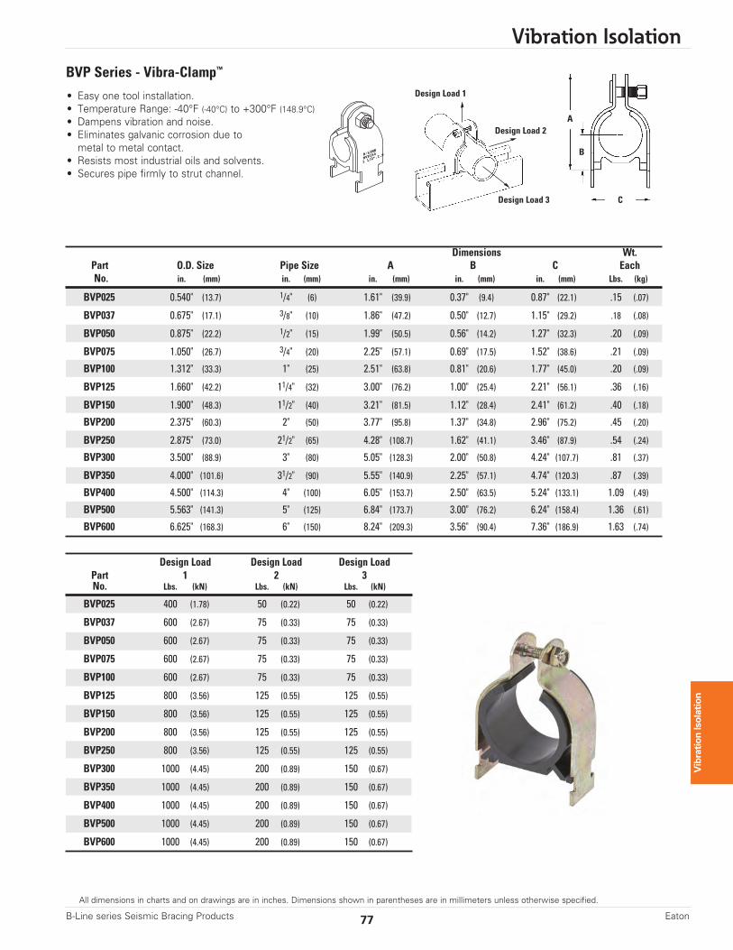
BVP Series - Vibra-Clamp™
• Easy one tool installation.• Temperature Range: -40°F (-40°C) to +300°F (148.9°C)• Dampens vibration and noise.• Eliminates galvanic corrosion due to metal to metal contact.
• Resists most industrial oils and solvents.• Secures pipe firmly to strut channel.
Dimensions Wt.Part O.D. Size Pipe Size A B C EachNo. in. (mm) in. (mm) in. (mm) in. (mm) in. (mm) Lbs. (kg)
BVP025 0.540" (13.7) 1/4" (6) 1.61" (39.9) 0.37" (9.4) 0.87" (22.1) .15 (.07)
BVP037 0.675" (17.1) 3/8" (10) 1.86" (47.2) 0.50" (12.7) 1.15" (29.2) .18 (.08)
BVP050 0.875" (22.2) 1/2" (15) 1.99" (50.5) 0.56" (14.2) 1.27" (32.3) .20 (.09)
BVP075 1.050" (26.7) 3/4" (20) 2.25" (57.1) 0.69" (17.5) 1.52" (38.6) .21 (.09)
BVP100 1.312" (33.3) 1" (25) 2.51" (63.8) 0.81" (20.6) 1.77" (45.0) .20 (.09)
BVP125 1.660" (42.2) 11/4" (32) 3.00" (76.2) 1.00" (25.4) 2.21" (56.1) .36 (.16)
BVP150 1.900" (48.3) 11/2" (40) 3.21" (81.5) 1.12" (28.4) 2.41" (61.2) .40 (.18)
BVP200 2.375" (60.3) 2" (50) 3.77" (95.8) 1.37" (34.8) 2.96" (75.2) .45 (.20)
BVP250 2.875" (73.0) 21/2" (65) 4.28" (108.7) 1.62" (41.1) 3.46" (87.9) .54 (.24)
BVP300 3.500" (88.9) 3" (80) 5.05" (128.3) 2.00" (50.8) 4.24" (107.7) .81 (.37)
BVP350 4.000" (101.6) 31/2" (90) 5.55" (140.9) 2.25" (57.1) 4.74" (120.3) .87 (.39)
BVP400 4.500" (114.3) 4" (100) 6.05" (153.7) 2.50" (63.5) 5.24" (133.1) 1.09 (.49)
BVP500 5.563" (141.3) 5" (125) 6.84" (173.7) 3.00" (76.2) 6.24" (158.4) 1.36 (.61)
BVP600 6.625" (168.3) 6" (150) 8.24" (209.3) 3.56" (90.4) 7.36" (186.9) 1.63 (.74)
Design Load Design Load Design LoadPart 1 2 3No. Lbs. (kN) Lbs. (kN) Lbs. (kN)
BVP025 400 (1.78) 50 (0.22) 50 (0.22)
BVP037 600 (2.67) 75 (0.33) 75 (0.33)
BVP050 600 (2.67) 75 (0.33) 75 (0.33)
BVP075 600 (2.67) 75 (0.33) 75 (0.33)
BVP100 600 (2.67) 75 (0.33) 75 (0.33)
BVP125 800 (3.56) 125 (0.55) 125 (0.55)
BVP150 800 (3.56) 125 (0.55) 125 (0.55)
BVP200 800 (3.56) 125 (0.55) 125 (0.55)
BVP250 800 (3.56) 125 (0.55) 125 (0.55)
BVP300 1000 (4.45) 200 (0.89) 150 (0.67)
BVP350 1000 (4.45) 200 (0.89) 150 (0.67)
BVP400 1000 (4.45) 200 (0.89) 150 (0.67)
BVP500 1000 (4.45) 200 (0.89) 150 (0.67)
BVP600 1000 (4.45) 200 (0.89) 150 (0.67)
B-LINE
B-LINE
BVP150
BVP150
1 1/2”
I.P
1 1/2” I.P..
C
A
B
Design Load 2
Design Load 1
Design Load 3
Vibration Isolation
78 B-Line series Seismic Bracing ProductsEaton
All dimensions in charts and on drawings are in inches. Dimensions shown in parentheses are in millimeters unless otherwise specified.
Vibration Isolation
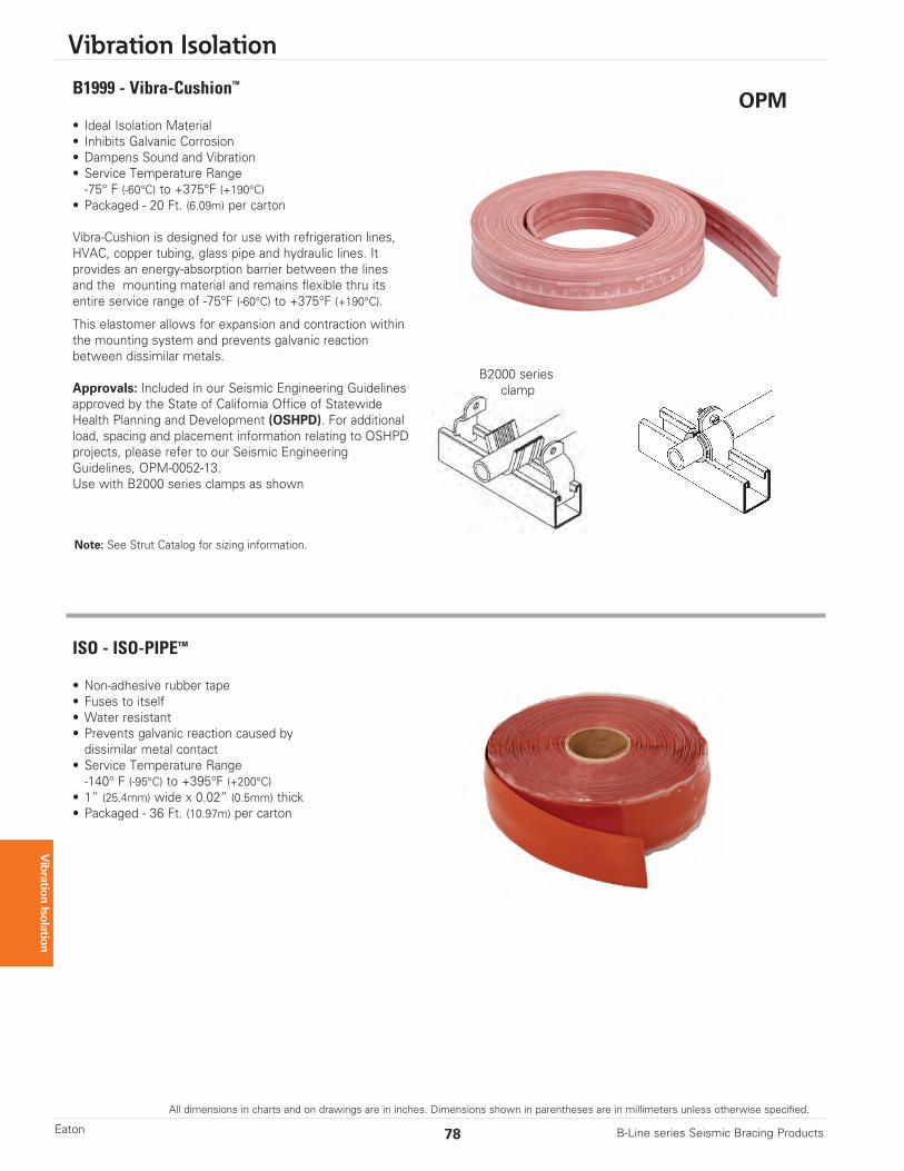
• Non-adhesive rubber tape• Fuses to itself• Water resistant• Prevents galvanic reaction caused by dissimilar metal contact
• Service Temperature Range-140° F (-95°C) to +395°F (+200°C)
• 1” (25.4mm) wide x 0.02” (0.5mm) thick• Packaged - 36 Ft. (10.97m) per carton
ISO - ISO-PIPE™
• Ideal Isolation Material• Inhibits Galvanic Corrosion• Dampens Sound and Vibration• Service Temperature Range-75° F (-60°C) to +375°F (+190°C)
• Packaged - 20 Ft. (6.09m) per carton
Vibra-Cushion is designed for use with refrigeration lines,HVAC, copper tubing, glass pipe and hydraulic lines. It provides an energy-absorption barrier between the lines and the mounting material and remains flexible thru itsentire service range of -75°F (-60°C) to +375°F (+190°C).
This elastomer allows for expansion and contraction withinthe mounting system and prevents galvanic reactionbetween dissimilar metals.
Approvals: Included in our Seismic Engineering Guidelinesapproved by the State of California Office of StatewideHealth Planning and Development (OSHPD). For additionalload, spacing and placement information relating to OSHPDprojects, please refer to our Seismic EngineeringGuidelines, OPM-0052-13.Use with B2000 series clamps as shown
B1999 - Vibra-Cushion™
Note: See Strut Catalog for sizing information.
OPM
B2000 seriesclamp