Embed Size (px)
Citation preview

PH-2
● Please read before training
General information
● Preparation
Instructionmanual
Contents
Whole Body Phantom PBU-50
~P. 1 P. 3
~P. 4 P. 9Assembly manual


General informationPlease read
Speci�cations
Whole body phantom PBU-50
The PBU-50 is life-size human phantom with a life-size synthetic skeleton embedded in radiological soft tissue substitute. There are no metal parts that would impair realistic imaging. The joints, knees, elbows, shoulders and hip-joints, are �exible and able to maintain the necessary positions. The phantom is separable into 10 parts facilitating a variety of application. A positioning stand for the head part comes with the set.
Whole body phantom PBU-50
Intended application: Positioning phantom for plain radiography
Length: approx.165cm Weight: approx. 50kg
Can be dismantled at: shoulders elbows, hip joints, knees, neck
Embedded organs: lungs with vessels, mediastinal space, liver, kidney
Movable joints and their range of movement
Shoulders: rotate 360 degrees to back and forward, 180 degrees side-ways
Cubital joints (bilateral): bend inward up to 90 degree
Coxae (bilateral): rotate forward up to 90 degrees, then rotate outward up to 45 degrees each. Articulatio genus (bilateral): bend up to 90 degrees.
Materials: Human tissue substitute (urethane, epoxy, etc.,)
Accessories: Positioning head stand 1 piece Flat head screwdriver 1 piece
Hand positioning belt 1 piece Sample images 1 set
Replacement parts: screws and connection tapes for Patella.
1
General informationPlease read
1) Bone trabeculae are observed only at hands.
2) Contours of the bones are slightly stranger than actual human x-ray image, to facilitate clear understanding.
3) Basically the phantom is designed to be radiographed under same setting as human body, though, the joints areas may require some adjustment to have better image.
1) Do not make the phantom to take the position unintended by the manufacturer. It may cause the breakage in the phantom if the joints are forced to bend or rotate to the directions or degrees of angles outside of designed movable range.
2) Do not remove the plastic protectors on the phantom s hands. The protector prevents the phantom �ngers from breaking.
3) Do not attempt to lift or carry the phantom if the head or limbs are attached to the trunk. Detach the joints before moving to avoid the excessive force on the joints.
4) Do not fasten the screws too tight.
5) The phantom is heavy and could cause damage not only to itself but to people or other objects. When you need to handle the assembled phantom, always do it by two or more people with utmost care.
6) Don’t mark on the phantom with pen or leave printed materials contacted on its surface. Ink marks on the phantom will be irremovable.
2
Please note
Caution
’

General informationPlease read
3
PBU-50 Components
#
10
11
12
13
14
15
16
17
18
19
20
Head
M10×20
M 6×60
M12×20
M 6
M 8×10
4
(lateral side)
(medial side)
(lateral side)
(medial side)
Parts name QTY #
#
Parts name QTYParts Parts
Connector for right hip joint
Connector for left hip joint 21
22
23
24
25
26
27
28
29
30
31
32
33
34
35
36
Nut for neck connection M12
Screw bolt for neck connection
Screw bolt for shoulder connection Screw bolt for parts
Screw bolt for elbow joint
Screw nut for elbow joint
Screw bolt for hip joint M8×35
Screw bolt for knee joint
Height adjustment panel
Connection tape for the patellae
Base panel
Neck connector
Neck connector �xture
Screw for �xture
Screw bolt M6×18
Neck-head connection plate
Trunk
Right upper arm
Left upper arm
Right forearm
Left forearm
Right thigh
Left thigh
Right lower leg
Left lower leg
Right patella
Left patella
Connector for shoulder A
Connector for right knee
Connector for left knee
Connector for right elbow
Connector for right elbow
Connector for left elbow
Connector for left elbow
1 1
1
1
1
1
1
1
2
2
2
2
10
4
4
6
1
1
1
1
1
1
1
1
1
1
2
2
1
11
1
1
1
1
37
38
39
40 1
1
1
2
3
4
5
6
7
8
9
Hand positioning belt
Supporting plate for right hip joint
Supporting plate for left hip joint 1
1
22.23
(Right or left)Connector for shoulder B
(Right or left)

4
Assembly manual
The number indicated on the photos above correspond to the page numbers in this manual.
P.5
P.6
P.6P.6
P.9P.9
P.6
P.7
P.7
P.8
P.8

5
Assembly manual
< >
【 Neck sub-assembly 】
【 Connection of the head and the trunk 】
2
NECK AND HEAD
1. Remove the two nuts for the neck connection (part #26) and remove the neck head connection plate (part #2) from the trunk.
2. Screw the neck head connection plate (part #2) on the head (part #1).
26
26
The circled numbers in the assembly images are parts numbers on the components table on page 3.
Nut for neck connection M12×2
27
Screw bolt for neck connection M10×20×2
※
3. Mount the assembled parts (parts #1 and #2) to the trunk and secure each side with a nut (part #26).
2
1
27 27
26

6
Assembly manual
ELBOWS
Assemble upper arm parts (part #4 or 5) and forearm parts (part #6 or 7) at joint section. Fix these parts with elbow connectors (part #16 or 18 and #17 or 19).
(lateral side)
(medial side)
Left and right upper arm
Left and right forearm
Connector for leftand right elbow
Connector for leftand right elbow
>>
M 6×60×4
M 6×4
Screw bolt for elbow jointScrew nut for elbow joint
29 30
7 5
4
6
16
17
18
29
1930
29
30
< >
Left and right upper armConnector for shoulder
SHOULDERS
281. Remove the two clear bolts (part #28) and remove the external shoulder connector parts A (part #14) and connector parts B (part #15). connection
M 8×10×4
Screw bolt for shoulder
Be careful not to mix up part #4 and 5. The shape of right and left arms are di�erent.Screw the bolts after con�rming the position of the screw hole.Caution
2. Then attach the upper arms (parts #4 and #5) at the ball joint to the trunk and place over the two connectors for the shoulder (parts #14 and #15). Secure the connectors with the clear bolts (part #28). Follow these steps for both left and right side of the trunk.
15
15
14
14
3
54
28

7
Assembly manual
< >
M12×20×4
KNEES
1. Connect the thigh (#8, 9) and lower leg (#10, 11) at the knee joint. Insert the dowel of the upper thigh through the hole of knee joint of lower thigh. Set the connector for knee (#24, 25) to the medial side then screw the knee joint bolt (#32) to �x it.
2. After �xing the knee joint, bend the knee and insert the connection tape of the patella (#12, 13) to the guide aperture of the thigh.
Screw bolt for knee joint 32
8
9
24 2532
1312
10 11
Insert the dowel of the upper thigh through the hole of the knee joint of lower leg.
Screw bolt for knee joint

8
Assembly manual
< >HIP JOINTS
1. Remove the three bolts (part #31) to remove the hip joint connectors (parts #20 and #21). The supporting plates (parts #22 and #23) are already attached at the time of delivery.
2. Mount the thighs (part#8, 9) so that the femur heads �t in the hip sockets and hold them in place with hip joints connectors (part# 20,21). Each hip joint connector is �xed to the trunk with three screws. Start from the screw in the center and move to the sides. Hold the thigh upright when you �x the screw at the rear end. Be careful not to confuse parts for left and for right.
Connector for left and right hip joint
Left and right thigh
Screw bolt for hip joint M8×35×6
Connector for left and right hip joint
8
31
21209
31
3
21 2320 22
31
9
Assembly manual
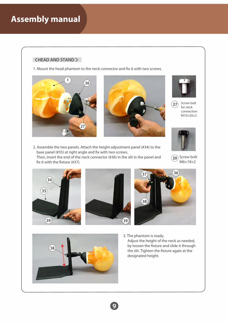
< >HEAD AND STAND
39
2. Assemble the two panels. Attach the height adjustment panel (#34) to the base panel (#35) at right angle and �x with two screws. Then, insert the end of the neck connector (#36) in the slit in the panel and �x it with the �xture (#37).
3. The phantom is ready. Adjust the height of the neck as needed, by loosen the �xture and slide it through the slit. Tighten the �xture again at the designated height.
1. Mount the head phantom to the neck connector and �x it with two screws.
Screw bolt M6×18×2
27 Screw bolt for neck connection M10×20×2
1
35
38
37
39 39
34
36
36
27
38

Don’t mark on the phantom with pen or leave printed materials contacted on its surface. Ink marks on the phantom will be irremovable.Caution
URL : http://www.kyotokagaku.come-mail : [email protected]
Worldwide Inquiries & Ordering
Kyotokagaku Head Office and Factories:
Kyotokagaku USA Office: USA and Canada sales and services3109 Lomita Boulevard, Torrance, CA 90505-5108, USA
2015.04
15 Kitanekoya-cho, Fushimi-ku, Kyoto, 612ー8388, JAPANTel: +81ー75ー605ー2510 Fax: +81ー75ー605ー2519
Tel: 1ー310ー325ー8860 Fax: 1ー310ー325ー8867