Embed Size (px)
Citation preview
PGP/PGMBushing Design
Catalog HY09-0300/US
Single/multiplepumps & motors
• Pressure to 4500 psi
• Pumps with flows toover 90 gpm
• Motors with outputsto over 150 hp
H E A V Y D U T Y C A S T I R O N
300/400 Series

300/400 SeriesPGP/PGM Bushing Design
2 Parker Hannifin CorporationGear Pump DivisionYoungstown, OH
FAILURE OR IMPROPER SELECTION OR IMPROPER USE OF THE PRODUCTS AND/OR SYSTEMS DESCRIBED HEREIN OR RELATED ITEMS CAN CAUSE DEATH, PERSONALINJURY AND PROPERTY DAMAGE.
This document and other information from The Company, its subsidiaries and authorized distributors provide product and/or system options for further investigation by users having technicalexpertise. It is important that you analyze all aspects of your application and review the information concerning the product or system in the current product catalog. Due to the varietyof operating conditions and applications for these products or systems, the user, through its own analysis and testing, is solely responsible for making the final selection of the productsand systems and assuring that all performance, safety and warning requirements of the application are met.
The products described herein, including without limitation, product features, specifications, designs, availability and pricing, are subject to change by The Company and its subsidiariesat any time without notice.
Offer of SaleThe items described in this document are hereby offered for sale by Parker Hannifin Corporation, its subsidiaries or its authorized distributors. This offer and its acceptance are governedby the provisions stated in the “Offer of Sale”.
© Copyright 2001, Parker Hannifin Corporation, All Rights Reserved.
WARNING
300/400 SeriesPGP/PGM Bushing Design
3 Parker Hannifin CorporationGear Pump DivisionYoungstown, OH
Index300 SeriesGeneral Information...............................................4
PL Factor............................................................5
General Data....................................................6
Por t ing.. . . . . . . . . . . . . . . . . . . . . . . . . . . . . . . . . . . . . . . . . . . . . . . . . . . . .7
Performance Curves...........................................8
Dimensional Data..............................................9
Performance Data............................................10
Coding................................................................14
400 SeriesDimensional Data............................................22
Special Assemblies............................................24
Offer of Sale..........................................................26
300/400 SeriesPGP/PGM Bushing Design
4 Parker Hannifin CorporationGear Pump DivisionYoungstown, OH
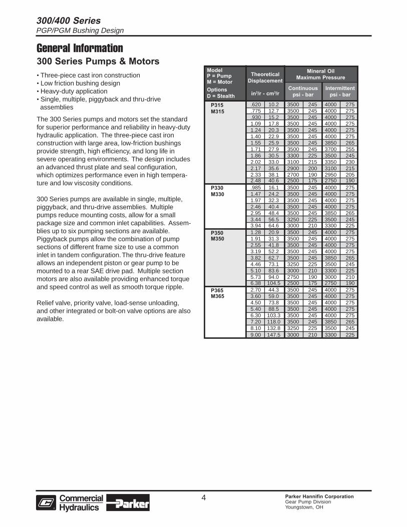
General Information300 Series Pumps & Motors• Three-piece cast iron construction• Low friction bushing design• Heavy-duty application• Single, multiple, piggyback and thru-drive assemblies
The 300 Series pumps and motors set the standardfor superior performance and reliability in heavy-dutyhydraulic application. The three-piece cast ironconstruction with large area, low-friction bushingsprovide strength, high efficiency, and long life insevere operating environments. The design includesan advanced thrust plate and seal configuration,which optimizes performance even in high tempera-ture and low viscosity conditions.
300 Series pumps are available in single, multiple,piggyback, and thru-drive assemblies. Multiplepumps reduce mounting costs, allow for a smallpackage size and common inlet capabilities. Assem-blies up to six pumping sections are available.Piggyback pumps allow the combination of pumpsections of different frame size to use a commoninlet in tandem configuration. The thru-drive featureallows an independent piston or gear pump to bemounted to a rear SAE drive pad. Multiple sectionmotors are also available providing enhanced torqueand speed control as well as smooth torque ripple.
Relief valve, priority valve, load-sense unloading,and other integrated or bolt-on valve options are alsoavailable.
P315 .620 10.2 3500 245 4000 275M315 .775 12.7 3500 245 4000 275
.930 15.2 3500 245 4000 2751.09 17.8 3500 245 4000 2751.24 20.3 3500 245 4000 2751.40 22.9 3500 245 4000 2751.55 25.9 3500 245 3850 2651.71 27.9 3500 245 3700 2551.86 30.5 3300 225 3500 2452.02 33.0 3100 215 3350 2302.17 35.6 2900 200 3100 2152.33 38.1 2700 190 2950 2052.48 40.6 2500 175 2750 190
P330 .985 16.1 3500 245 4000 275M330 1.47 24.2 3500 245 4000 275
1.97 32.3 3500 245 4000 2752.46 40.4 3500 245 4000 2752.95 48.4 3500 245 3850 2653.44 56.5 3250 225 3500 2453.94 64.6 3000 210 3300 225
P350 1.28 20.9 3500 245 4000 275M350 1.91 31.3 3500 245 4000 275
2.55 41.8 3500 245 4000 2753.19 52.2 3500 245 4000 2753.82 62.7 3500 245 3850 2654.46 73.1 3250 225 3500 2455.10 83.6 3000 210 3300 2255.73 94.0 2750 190 3000 2106.38 104.5 2500 175 2750 190
P365 2.70 44.3 3500 245 4000 275M365 3.60 59.0 3500 245 4000 275
4.50 73.8 3500 245 4000 2755.40 88.5 3500 245 4000 2756.30 103.3 3500 245 4000 2757.20 118.0 3500 245 3850 2658.10 132.8 3250 225 3500 2459.00 147.5 3000 210 3300 225
ModelP = PumpM = MotorOptionsD = Stealth
TheoreticalDisplacement
in3/r - cm3/r
Mineral OilMaximum Pressure
Continuouspsi - bar
Intermittentpsi - bar
300/400 SeriesPGP/PGM Bushing Design
5 Parker Hannifin CorporationGear Pump DivisionYoungstown, OH
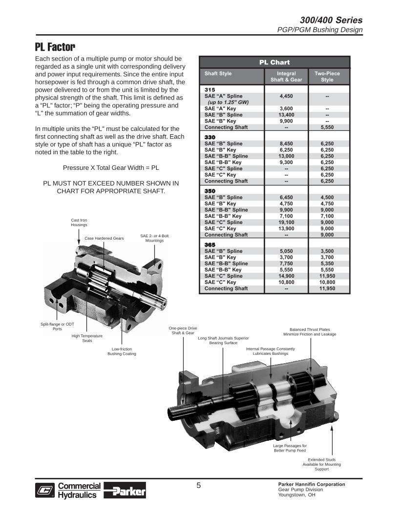
One-piece DriveShaft & Gear
Long Shaft Journals SuperiorBearing Surface
Internal Passage ConstantlyLubricates Bushings
Balanced Thrust PlatesMinimize Friction and Leakage
Extended StudsAvailable for Mounting
Support
Large Passages forBetter Pump Feed
Cast IronHousings
Case Hardened GearsSAE 2- or 4-Bolt
Mountings
Split-flange or ODTPorts
High TemperatureSeals
Low-frictionBushing Coating
PL FactorEach section of a multiple pump or motor should beregarded as a single unit with corresponding deliveryand power input requirements. Since the entire inputhorsepower is fed through a common drive shaft, thepower delivered to or from the unit is limited by thephysical strength of the shaft. This limit is defined asa “PL" factor; “P" being the operating pressure and“L" the summation of gear widths.
In multiple units the “PL" must be calculated for thefirst connecting shaft as well as the drive shaft. Eachstyle or type of shaft has a unique “PL" factor asnoted in the table to the right.
Pressure X Total Gear Width = PL
PL MUST NOT EXCEED NUMBER SHOWN INCHART FOR APPROPRIATE SHAFT.
PL Chart
Shaft Style Integral Two-PieceShaft & Gear Style
315SAE “A" Spline 4,450 -- (up to 1.25" GW)SAE “A" Key 3,600 --SAE “B" Spline 13,400 --SAE “B" Key 9,900 --Connecting Shaft -- 5,550
330330330330330SAE “B" Spline 8,450 6,250SAE “B" Key 6,250 6,250SAE “B-B" Spline 13,000 6,250SAE “B-B" Key 9,300 6,250SAE “C" Spline -- 6,250SAE “C" Key -- 6,250Connecting Shaft -- 6,250
350350350350350SAE “B" Spline 6,450 4,500SAE “B" Key 4,750 4,750SAE “B-B" Spline 9,900 9,000SAE “B-B" Key 7,100 7,100SAE “C" Spline 19,100 9,000SAE “C" Key 13,900 9,000Connecting Shaft -- 9,000
365365365365365SAE “B" Spline 5,050 3,500SAE “B" Key 3,700 3,700SAE “B-B" Spline 7,750 5,350SAE “B-B" Key 5,550 5,550SAE “C" Spline 14,900 11,950SAE “C" Key 10,800 10,800Connecting Shaft -- 11,950
300/400 SeriesPGP/PGM Bushing Design
6 Parker Hannifin CorporationGear Pump DivisionYoungstown, OH
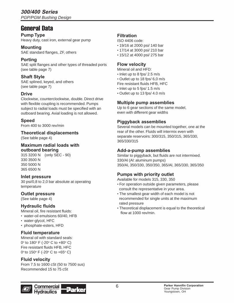
General DataPump TypeHeavy duty, cast iron, external gear pump
MountingSAE standard flanges, ZF, others
PortingSAE split flanges and other types of threaded ports(see table page 7)
Shaft StyleSAE splined, keyed, and others(see table page 7)
DriveClockwise, counterclockwise, double. Direct drivewith flexible coupling is recommended. Pumpssubject to radial loads must be specified with anoutboard bearing. Axial loading is not allowed.
SpeedFrom 400 to 3000 rev/min
Theoretical displacements(See table page 4)
Maximum radial loads withoutboard bearing315 3200 N (only SEC - 90)330 3500 N350 5000 N365 6500 N
Inlet pressure30 psi/0,8 to 2,0 bar absolute at operatingtemperature
Outlet pressure(See table page 4)
Hydraulic fluidsMineral oil, fire resistant fluids:• water-oil emulsions 60/40, HFB• water-glycol, HFC• phosphate-esters, HFD
Fluid temperatureMineral oil with standard seals:0o to 180o F (-20o C to +80o C)Fire resistant fluids HFB, HFC0o to 150o F (-20o C to +65o C)
Fluid velocityFrom 7.5 to 1600 cSt (50 to 7500 sus)Recommended 15 to 75 cSt
FiltrationISO 4406 code:• 19/16 at 2000 psi/ 140 bar• 17/14 at 3000 psi/ 210 bar• 15/12 at 4000 psi/ 275 bar
Flow velocityMineral oil and HFD:• Inlet up to 8 fps/ 2.5 m/s• Outlet up to 18 fps/ 6,0 m/sFire resistant fluids HFB, HFC• Inlet up to 5 fps/ 1.5 m/s• Outlet up to 13 fps/ 4.0 m/s
Multiple pump assembliesUp to 6 gear sections of the same model,even with different gear widths
Piggyback assembliesSeveral models can be mounted together, one at therear of the other. Fluids will intermix even withseparate reservoirs: 300/315, 350/315, 365/330,365/330/315
Add-a-pump assembliesSimilar to piggyback, but fluids are not intermixed.330/Al (Al: aluminum pumps)350/Al, 350/330, 350/350, 365/Al, 365/330, 365/350
Pumps with priority outletAvailable for models 315, 330, 350• For operation outside given parameters, please consult the representative in your area.• The smallest gear width of each model is not recommended for single units at the maximum rated pressure• Theoretical displacement is equal to the theoretical
flow at 1000 rev/min.
300/400 SeriesPGP/PGM Bushing Design
7 Parker Hannifin CorporationGear Pump DivisionYoungstown, OH
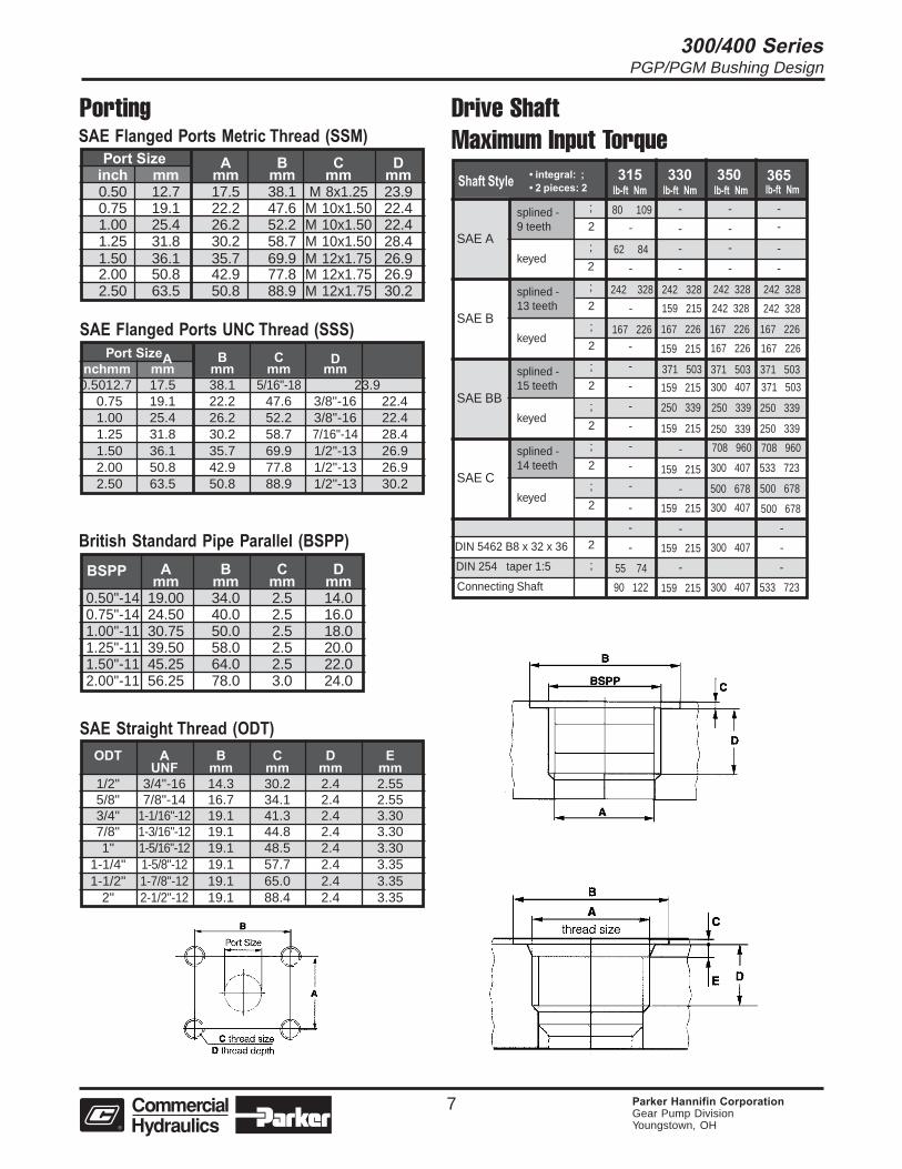
ODT A B C D EUNF mm mm mm mm
1/2" 3/4"-16 14.3 30.2 2.4 2.555/8" 7/8"-14 16.7 34.1 2.4 2.553/4" 1-1/16"-12 19.1 41.3 2.4 3.307/8" 1-3/16"-12 19.1 44.8 2.4 3.301" 1-5/16"-12 19.1 48.5 2.4 3.30
1-1/4" 1-5/8"-12 19.1 57.7 2.4 3.351-1/2" 1-7/8"-12 19.1 65.0 2.4 3.35
2" 2-1/2"-12 19.1 88.4 2.4 3.35
SAE Straight Thread (ODT)
British Standard Pipe Parallel (BSPP) BSPP A B C D
mm mm mm mm0.50"-14 19.00 34.0 2.5 14.00.75"-14 24.50 40.0 2.5 16.01.00"-11 30.75 50.0 2.5 18.01.25"-11 39.50 58.0 2.5 20.01.50"-11 45.25 64.0 2.5 22.02.00"-11 56.25 78.0 3.0 24.0
Port SizeA B C Dinchmm mm mm mm mm0.5012.7 17.5 38.1 5/16"-18 23.9
0.75 19.1 22.2 47.6 3/8"-16 22.41.00 25.4 26.2 52.2 3/8"-16 22.41.25 31.8 30.2 58.7 7/16"-14 28.41.50 36.1 35.7 69.9 1/2"-13 26.92.00 50.8 42.9 77.8 1/2"-13 26.92.50 63.5 50.8 88.9 1/2"-13 30.2
SAE Flanged Ports UNC Thread (SSS)
PortingSAE Flanged Ports Metric Thread (SSM) Port Size A B C D
inch mm mm mm mm mm0.50 12.7 17.5 38.1 M 8x1.25 23.90.75 19.1 22.2 47.6 M 10x1.50 22.41.00 25.4 26.2 52.2 M 10x1.50 22.41.25 31.8 30.2 58.7 M 10x1.50 28.41.50 36.1 35.7 69.9 M 12x1.75 26.92.00 50.8 42.9 77.8 M 12x1.75 26.92.50 63.5 50.8 88.9 M 12x1.75 30.2
Drive ShaftMaximum Input Torque
Shaft Style 365350330315
-
lb-ft Nm lb-ft Nmlb-ft Nmlb-ft Nm
-
-
-
-
-
-
-
-
-
-
-
-
-
-
-
-
-
-
-
-
-
-
SAE A
splined -9 teeth
splined -13 teeth
splined -15 teeth
splined -14 teeth
keyed
keyed
keyed
keyed
SAE B
SAE BB
SAE C
• integral: ;• 2 pieces: 2
80 109
62 84
242 328
-
-
-
167 226
;
2
;
2
;
2
;
2
;
2
;
2
;
2
;
2
242 328 242 328 242 328
242 328242 328159 215
159 215
159 215
159 215
159 215
159 215
159 215
159 21590 122
55 74
2
; -
-
-
-
250 339
371 503
167 226 167 226 167 226
167 226167 226
371 503 371 503
371 503300 407
300 407
300 407
300 407
533 723
533 723
500 678
-
-
-
500 678500 678
300 407
708 960 708 960
250 339 250 339
250 339 250 339
Connecting Shaft
DIN 5462 B8 x 32 x 36
DIN 254 taper 1:5
300/400 SeriesPGP/PGM Bushing Design
8 Parker Hannifin CorporationGear Pump DivisionYoungstown, OH
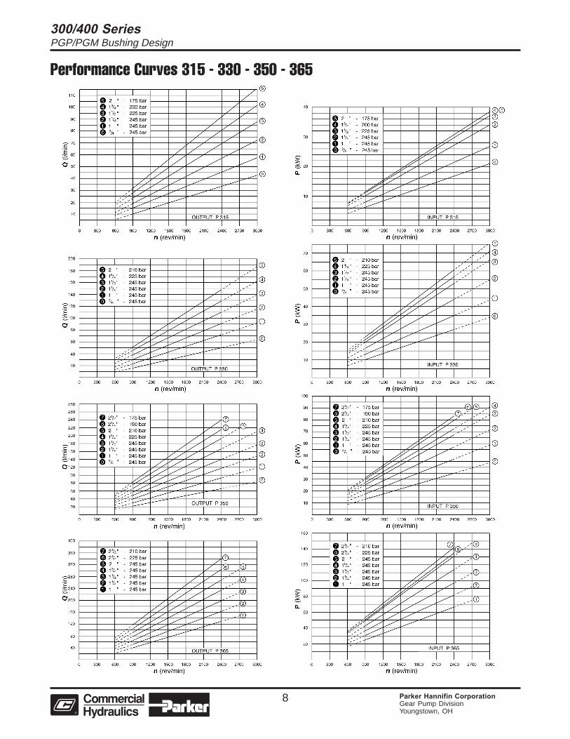
Performance Curves 315 - 330 - 350 - 365
300/400 SeriesPGP/PGM Bushing Design
9 Parker Hannifin CorporationGear Pump DivisionYoungstown, OH
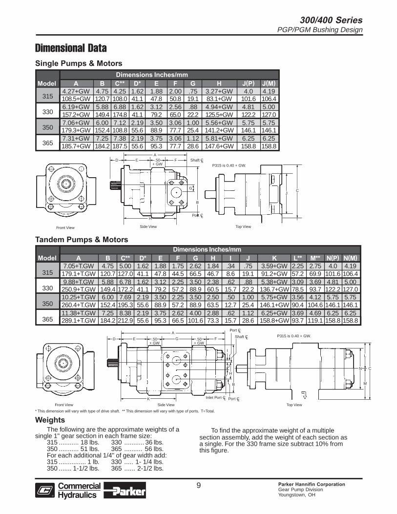
Dimensional DataSingle Pumps & Motors
315
330
350
365
Dimensions Inches/mmModel A B C** D* E F G H J(P) J(M)
4.27+GW 4.75 4.25 1.62 1.88 2.00 .75 3.27+GW 4.0 4.19108.5+GW 120.7 108.0 41.1 47.8 50.8 19.1 83.1+GW 101.6 106.46.19+GW 5.88 6.88 1.62 3.12 2.56 .88 4.94+GW 4.81 5.00157.2+GW 149.4 174.8 41.1 79.2 65.0 22.2 125.5+GW 122.2 127.07.06+GW 6.00 7.12 2.19 3.50 3.06 1.00 5.56+GW 5.75 5.75179.3+GW 152.4 108.8 55.6 88.9 77.7 25.4 141.2+GW 146.1 146.17.31+GW 7.25 7.38 2.19 3.75 3.06 1.12 5.81+GW 6.25 6.25185.7+GW 184.2 187.5 55.6 95.3 77.7 28.6 147.6+GW 158.8 158.8
315
330
350
365
ModelDimensions Inches/mm
A B C** D* E F G H I J K L** M** N(P) N(M)7.05+T.GW 4.75 5.00 1.62 1.88 1.75 2.62 1.84 .34 .75 3.59+GW 2.25 2.75 4.0 4.19179.1+T.GW 120.7 127.0 41.1 47.8 44.5 66.5 46.7 8.6 19.1 91.2+GW 57.2 69.9 101.6 106.49.88+T.GW 5.88 6.78 1.62 3.12 2.25 3.50 2.38 .62 .88 5.38+GW 3.09 3.69 4.81 5.00250.9+T.GW 149.4 172.2 41.1 79.2 57.2 88.9 60.5 15.7 22.2 136.7+GW 78.5 93.7 122.2 127.010.25+T.GW 6.00 7.69 2.19 3.50 2.25 3.50 2.50 .50 1.00 5.75+GW 3.56 4.12 5.75 5.75260.4+T.GW 152.4 195.3 55.6 88.9 57.2 88.9 63.5 12.7 25.4 146.1+GW 90.4 104.6 146.1 146.111.38+T.GW 7.25 8.38 2.19 3.75 2.62 4.00 2.88 .62 1.12 6.25+GW 3.69 4.69 6.25 6.25289.1+T.GW 184.2 212.9 55.6 95.3 66.5 101.6 73.3 15.7 28.6 158.8+GW 93.7 119.1 158.8 158.8
Tandem Pumps & Motors
WeightsThe following are the approximate weights of a
single 1" gear section in each frame size:315 ........... 18 lbs. 330 ........... 36 lbs.350 ........... 51 lbs. 365 .......... 56 lbs.For each additional 1/4" of gear width add:315 ............... 1 lb. 330 ..... 1- 1/4 lbs.350 ....... 1-1/2 lbs. 365 ...... 2-1/2 lbs.
* This dimension will vary with type of drive shaft. ** This dimension will vary with type of ports. T=Total.
Front View Side View Top View
Front View Side View Top View
To find the approximate weight of a multiplesection assembly, add the weight of each section asa single. For the 330 frame size subtract 10% fromthis figure.
H
D E .50+ GW
F Shaft C
G
L
Port CL
B
A
D E .50+ GW
G Shaft CL
Port CLA
.50+ GW
K
F
J
H
B
Port CLInlet Port CL
C
M
L
N
CJ
P315 is 0.40 + GW.
P315 is 0.40 + GW.
I
300/400 SeriesPGP/PGM Bushing Design
10 Parker Hannifin CorporationGear Pump DivisionYoungstown, OH
speed Gear Widthsrpm 1/2" 3/4" 1" 1-1/4" 1-1/2" 1-3/4" 2"
2.0 3.2 4.4 5.5 6.7 7.9 9.08 12 17 21 26 30 345 8 11 13 15 15 154 6 8 10 11 11 11
2.8 4.4 6.0 7.6 9.2 10.7 12.211 17 23 29 35 40 467 11 14 18 20 21 205 8 11 13 15 15 15
3.6 5.6 7.7 9.6 11.6 13.5 15.414 21 29 36 44 51 589 13 18 22 25 26 257 10 13 16 19 19 19
4.4 6.8 9.3 11.6 14.0 16.3 18.617 26 35 44 53 62 7011 16 21 27 30 31 308 12 16 20 22 23 23
5.2 8.1 10.9 13.6 16.4 19.1 21.820 30 41 51 62 72 8312 19 25 31 35 36 359 14 18 23 26 27 26
6.0 9.3 12.5 15.6 18.8 21.9 25.123 35 47 59 71 83 9514 21 28 35 40 41 4011 16 21 26 30 31 307.7 11.7 15.7 19.6 23.7 27.6 31.529 44 59 74 90 104 11918 27 35 44 50 51 5113 20 26 33 37 38 38
900
1200
1500
1800
2100
2400
3000
Note: In accordance with our policy of continuing product development, we reserve the right to change specifications shown in this catalog without notice.
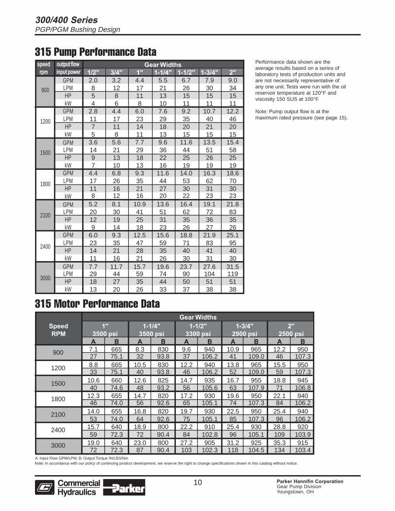
315 Pump Performance Data
315 Motor Performance Data
900
1200
1500
1800
2100
2400
3000
A: Input Flow GPM/LPM; B: Output Torque IN/LBS/Nm
Performance data shown are theaverage results based on a series oflaboratory tests of production units andare not necessarily representative ofany one unit. Tests were run with the oilreservoir temperature at 120°F andviscosity 150 SUS at 100°F.
Note: Pump output flow is at themaximum rated pressure (see page 15).
Gear WidthsSpeed 1" 1-1/4" 1-1/2" 1-3/4" 2"RPM 3500 psi 3500 psi 3300 psi 2900 psi 2500 psi
A B A B A B A B A B7.1 665 8.3 830 9.6 940 10.9 965 12.2 95027 75.1 32 93.8 37 106.2 41 109.0 46 107.38.8 665 10.5 830 12.2 940 13.8 965 15.5 95033 75.1 40 93.8 46 106.2 52 109.0 59 107.3
10.6 660 12.6 825 14.7 935 16.7 955 18.8 94540 74.6 48 93.2 56 105.6 63 107.9 71 106.8
12.3 655 14.7 820 17.2 930 19.6 950 22.1 94046 74.0 56 92.6 65 105.1 74 107.3 84 106.2
14.0 655 16.8 820 19.7 930 22.5 950 25.4 94053 74.0 64 92.6 75 105.1 85 107.3 96 106.2
15.7 640 18.9 800 22.2 910 25.4 930 28.8 92059 72.3 72 90.4 84 102.8 96 105.1 109 103.9
19.0 640 23.0 800 27.2 905 31.2 925 35.3 91572 72.3 87 90.4 103 102.3 118 104.5 134 103.4
output flow input power
GPMLPMHPkW
GPMLPMHPkW
GPMLPMHPkW
GPMLPMHPkW
GPMLPMHPkW
GPMLPMHPkW
GPMLPMHPkW
300/400 SeriesPGP/PGM Bushing Design
11 Parker Hannifin CorporationGear Pump DivisionYoungstown, OH
speed Gear Widthsrpm 1/2" 3/4" 1" 1-1/4" 1-1/2" 1-3/4" 2"
3.2 5.1 7.0 8.8 10.6 12.4 14.312 19 26 33 40 47 549 13 17 21 26 28 296 10 13 16 19 21 22
4.5 7.0 9.5 12.0 14.5 16.9 19.417 26 36 45 55 64 7311 17 23 28 34 37 398 13 17 21 25 28 29
5.8 8.9 12.1 15.2 18.3 21.4 24.522 34 46 57 69 81 9314 21 28 35 43 46 4911 16 21 26 32 34 367.1 10.8 14.7 18.4 22.1 25.9 29.627 41 55 70 84 98 11217 26 34 43 51 55 5813 19 25 32 38 41 448.4 12.7 17.2 21.6 26.0 30.3 34.732 48 65 82 98 115 13120 30 40 50 60 65 6815 22 30 37 44 48 519.6 14.7 19.8 24.8 29.8 34.8 39.836 55 75 94 113 132 15123 34 45 57 68 74 7817 25 34 42 51 55 58
12.2 18.5 24.9 31.2 37.5 43.8 50.146 70 94 118 142 166 19028 43 57 71 85 92 9721 32 42 53 64 69 73
900
1200
1500
1800
2100
2400
3000
Note: In accordance with our policy of continuing product development, we reserve the right to change specifications shown in this catalog without notice.
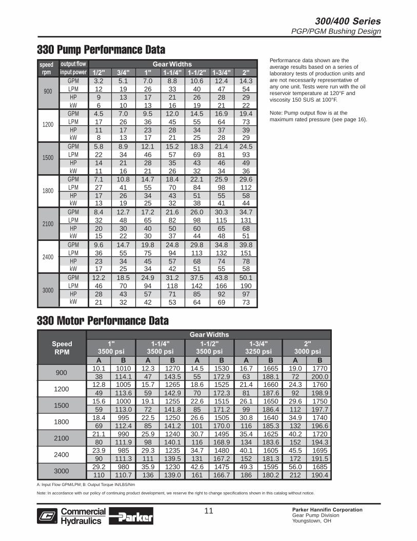
330 Pump Performance Data
330 Motor Performance Data
900
1200
1500
1800
2100
2400
3000
A: Input Flow GPM/LPM; B: Output Torque IN/LBS/Nm
Performance data shown are theaverage results based on a series oflaboratory tests of production units andare not necessarily representative ofany one unit. Tests were run with the oilreservoir temperature at 120°F andviscosity 150 SUS at 100°F.
Note: Pump output flow is at themaximum rated pressure (see page 16).
Gear WidthsSpeed 1" 1-1/4" 1-1/2" 1-3/4" 2"RPM 3500 psi 3500 psi 3500 psi 3250 psi 3000 psi
A B A B A B A B A B10.1 1010 12.3 1270 14.5 1530 16.7 1665 19.0 177038 114.1 47 143.5 55 172.9 63 188.1 72 200.0
12.8 1005 15.7 1265 18.6 1525 21.4 1660 24.3 176049 113.6 59 142.9 70 172.3 81 187.6 92 198.9
15.6 1000 19.1 1255 22.6 1515 26.1 1650 29.6 175059 113.0 72 141.8 85 171.2 99 186.4 112 197.7
18.4 995 22.5 1250 26.6 1505 30.8 1640 34.9 174069 112.4 85 141.2 101 170.0 116 185.3 132 196.6
21.1 990 25.9 1240 30.7 1495 35.4 1625 40.2 172080 111.9 98 140.1 116 168.9 134 183.6 152 194.3
23.9 985 29.3 1235 34.7 1480 40.1 1605 45.5 169590 111.3 111 139.5 131 167.2 152 181.3 172 191.5
29.2 980 35.9 1230 42.6 1475 49.3 1595 56.0 1685110 110.7 136 139.0 161 166.7 186 180.2 212 190.4
output flowinput power
GPMLPMHPkW
GPMLPMHPkW
GPMLPMHPkW
GPMLPMHPkW
GPMLPMHPkW
GPMLPMHPkW
GPMLPMHPkW
300/400 SeriesPGP/PGM Bushing Design
12 Parker Hannifin CorporationGear Pump DivisionYoungstown, OH
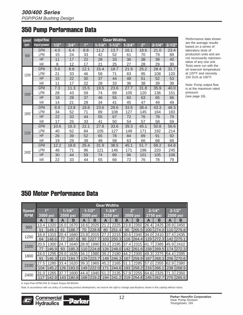
Gear WidthsSpeed 1" 1-1/4" 1-1/2" 1-3/4" 2" 2-1/4" 2-1/2"RPM 3500 psi 3500 psi 3500 psi 3250 psi 3000 psi 2750 psi 2500 psi
A B A B A B A B A B A B A B13.4 1320 16.0 1670 18.6 2025 21.2 2225 23.8 2350 26.4 2425 28.9 245051 149.1 61 188.7 70 228.8 80 251.4 90 265.5 100 274.0 110 276.8
16.9 1315 20.4 1660 23.8 2015 27.2 2215 30.6 2340 34.0 2410 37.4 243564 148.6 77 187.6 90 227.7 103 250.3 116 264.4 129 272.3 142 275.1
20.5 1300 24.7 1640 28.9 1990 33.2 2195 37.4 2315 41.7 2385 45.9 241077 146.9 93 185.3 110 224.8 126 248.0 142 261.6 158 269.5 174 272.3
24.0 1295 29.0 1635 34.1 1980 39.2 2180 44.2 2300 49.3 2375 54.4 239591 146.3 110 184.7 129 223.7 148 246.3 167 259.9 187 268.3 206 270.6
27.5 1285 33.4 1620 39.3 1965 45.2 2165 51.1 2285 57.0 2355 62.9 2380104 145.2 126 183.0 149 222.0 171 244.6 193 258.2 216 266.1 238 268.931.0 1265 37.7 1600 44.4 1940 51.2 2135 57.9 2255 64.6 2325 71.3 2350117 142.9 143 180.8 168 219.2 194 241.2 219 254.8 245 262.7 270 265.5
speed Gear Widthsrpm 1/2" 3/4" 1" 1-1/4" 1-1/2" 1-3/4" 2" 2-1/4" 2-1/2"
4.0 6.4 8.8 11.2 13.7 16.1 18.6 21.0 23.415 24 33 42 52 61 70 79 8911 17 22 28 33 36 38 39 408 12 17 21 25 27 28 29 30
5.6 8.8 12.1 15.4 18.7 21.9 25.2 28.4 31.721 33 46 58 71 83 95 108 12015 22 30 37 44 48 51 52 5311 17 22 28 33 36 38 39 397.3 11.3 15.5 19.5 23.6 27.7 31.8 35.9 40.028 43 59 74 89 105 120 136 15118 28 37 46 55 60 63 65 6614 21 28 34 41 45 47 49 498.9 13.8 18.8 23.6 28.6 33.5 38.4 43.3 48.334 52 71 89 108 127 145 164 18322 33 44 55 67 72 76 78 7917 25 33 41 50 54 57 58 59
10.6 16.3 22.1 27.8 33.6 39.3 45.1 50.8 56.640 62 84 105 127 149 171 192 21426 39 52 65 78 84 89 91 9219 29 39 48 58 63 66 68 69
12.2 18.8 25.4 31.9 38.5 45.1 51.7 58.2 64.846 71 96 121 146 171 196 220 24530 44 59 74 89 96 101 105 10622 33 44 55 66 72 76 78 79
Note: In accordance with our policy of continuing product development, we reserve the right to change specifications shown in this catalog without notice.
900
1200
1500
1800
2100
2400
350 Pump Performance Data
350 Motor Performance Data
A: Input Flow GPM/LPM; B: Output Torque IN/LBS/Nm
Performance data shownare the average resultsbased on a series oflaboratory tests ofproduction units and arenot necessarily represen-tative of any one unit.Tests were run with theoil reservoir temperatureat 120°F and viscosity150 SUS at 100°F.
Note: Pump output flowis at the maximum ratedpressure(see page 18).
output flowinput power
GPMLPMHPkW
GPMLPMHPkW
GPMLPMHPkW
GPMLPMHPkW
GPMLPMHPkW
GPMLPMHPkW
900
1200
1500
1800
2100
2400
300/400 SeriesPGP/PGM Bushing Design
13 Parker Hannifin CorporationGear Pump DivisionYoungstown, OH
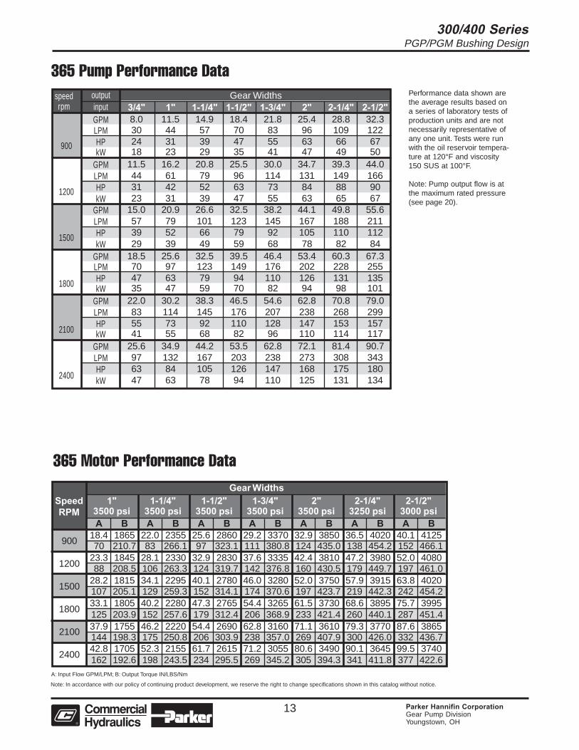
Gear WidthsSpeed 1" 1-1/4" 1-1/2" 1-3/4" 2" 2-1/4" 2-1/2"RPM 3500 psi 3500 psi 3500 psi 3500 psi 3500 psi 3250 psi 3000 psi
A B A B A B A B A B A B A B18.4 1865 22.0 2355 25.6 2860 29.2 3370 32.9 3850 36.5 4020 40.1 412570 210.7 83 266.1 97 323.1 111 380.8 124 435.0 138 454.2 152 466.1
23.3 1845 28.1 2330 32.9 2830 37.6 3335 42.4 3810 47.2 3980 52.0 408088 208.5 106 263.3 124 319.7 142 376.8 160 430.5 179 449.7 197 461.0
28.2 1815 34.1 2295 40.1 2780 46.0 3280 52.0 3750 57.9 3915 63.8 4020107 205.1 129 259.3 152 314.1 174 370.6 197 423.7 219 442.3 242 454.233.1 1805 40.2 2280 47.3 2765 54.4 3265 61.5 3730 68.6 3895 75.7 3995125 203.9 152 257.6 179 312.4 206 368.9 233 421.4 260 440.1 287 451.437.9 1755 46.2 2220 54.4 2690 62.8 3160 71.1 3610 79.3 3770 87.6 3865144 198.3 175 250.8 206 303.9 238 357.0 269 407.9 300 426.0 332 436.742.8 1705 52.3 2155 61.7 2615 71.2 3055 80.6 3490 90.1 3645 99.5 3740162 192.6 198 243.5 234 295.5 269 345.2 305 394.3 341 411.8 377 422.6
900
1200
1500
1800
2100
2400
900
1200
1500
1800
2100
2400
Note: In accordance with our policy of continuing product development, we reserve the right to change specifications shown in this catalog without notice.
365 Pump Performance Data
365 Motor Performance Data
A: Input Flow GPM/LPM; B: Output Torque IN/LBS/Nm
Performance data shown arethe average results based ona series of laboratory tests ofproduction units and are notnecessarily representative ofany one unit. Tests were runwith the oil reservoir tempera-ture at 120°F and viscosity150 SUS at 100°F.
Note: Pump output flow is atthe maximum rated pressure(see page 20).
speed Gear Widthsrpm 3/4" 1" 1-1/4" 1-1/2" 1-3/4" 2" 2-1/4" 2-1/2"
8.0 11.5 14.9 18.4 21.8 25.4 28.8 32.330 44 57 70 83 96 109 12224 31 39 47 55 63 66 6718 23 29 35 41 47 49 50
11.5 16.2 20.8 25.5 30.0 34.7 39.3 44.044 61 79 96 114 131 149 16631 42 52 63 73 84 88 9023 31 39 47 55 63 65 67
15.0 20.9 26.6 32.5 38.2 44.1 49.8 55.657 79 101 123 145 167 188 21139 52 66 79 92 105 110 11229 39 49 59 68 78 82 84
18.5 25.6 32.5 39.5 46.4 53.4 60.3 67.370 97 123 149 176 202 228 25547 63 79 94 110 126 131 13535 47 59 70 82 94 98 101
22.0 30.2 38.3 46.5 54.6 62.8 70.8 79.083 114 145 176 207 238 268 29955 73 92 110 128 147 153 15741 55 68 82 96 110 114 117
25.6 34.9 44.2 53.5 62.8 72.1 81.4 90.797 132 167 203 238 273 308 34363 84 105 126 147 168 175 18047 63 78 94 110 125 131 134
outputinputGPMLPMHPkW
GPMLPMHPkW
GPMLPMHPkW
GPMLPMHPkW
GPMLPMHPkW
GPMLPMHPkW
300/400 SeriesPGP/PGM Bushing Design
14 Parker Hannifin CorporationGear Pump DivisionYoungstown, OH
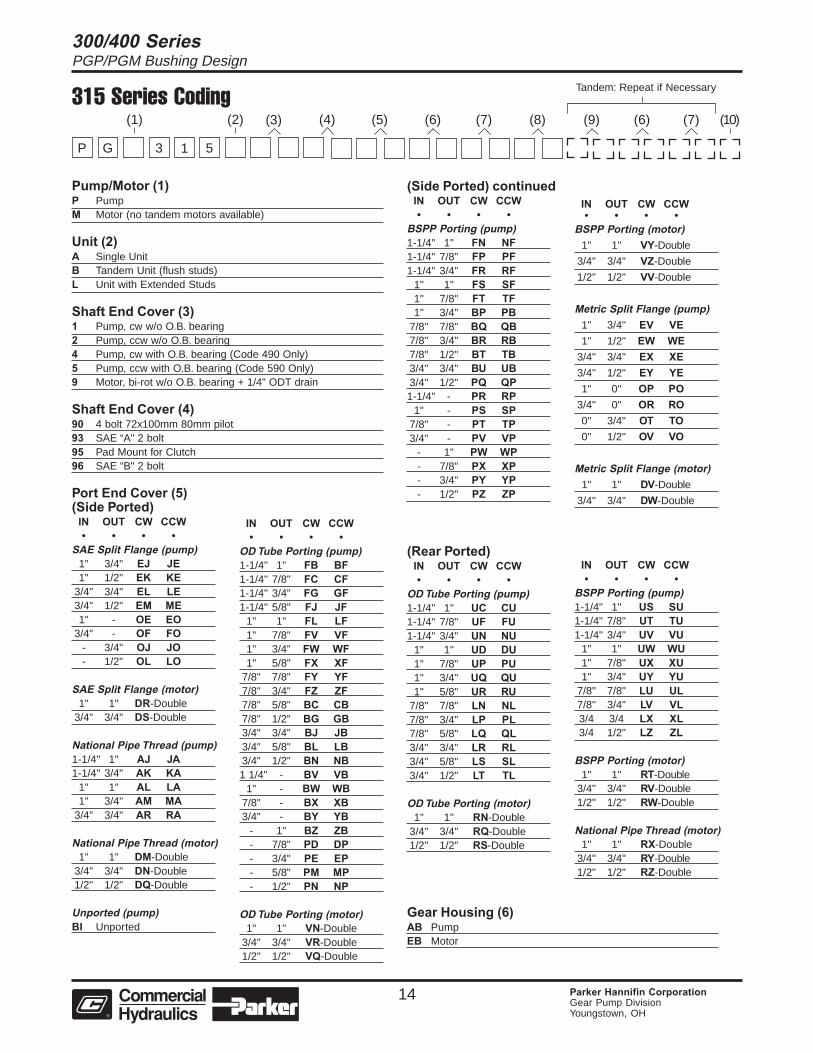
315 Series Coding
Pump/Motor (1)P PumpM Motor (no tandem motors available)
Unit (2)A Single UnitB Tandem Unit (flush studs)L Unit with Extended Studs
Shaft End Cover (3)1 Pump, cw w/o O.B. bearing2 Pump, ccw w/o O.B. bearing4 Pump, cw with O.B. bearing (Code 490 Only)5 Pump, ccw with O.B. bearing (Code 590 Only)9 Motor, bi-rot w/o O.B. bearing + 1/4" ODT drain
Shaft End Cover (4)90 4 bolt 72x100mm 80mm pilot93 SAE “A" 2 bolt95 Pad Mount for Clutch96 SAE “B" 2 bolt
Port End Cover (5)(Side Ported)
IN OUT CW CCW• • • •
SAE Split Flange (pump)1" 3/4" EJ JE1" 1/2" EK KE
3/4" 3/4" EL LE3/4" 1/2" EM ME1" - OE EO
3/4" - OF FO- 3/4" OJ JO- 1/2" OL LO
SAE Split Flange (motor)1" 1" DR-Double
3/4" 3/4" DS-Double
National Pipe Thread (pump)1-1/4" 1" AJ JA1-1/4" 3/4" AK KA
1" 1" AL LA1" 3/4" AM MA
3/4" 3/4" AR RA
National Pipe Thread (motor)1" 1" DM-Double
3/4" 3/4" DN-Double1/2" 1/2" DQ-Double
Unported (pump)BI Unported
IN OUT CW CCW• • • •
OD Tube Porting (pump)1-1/4" 1" FB BF1-1/4" 7/8" FC CF1-1/4" 3/4" FG GF1-1/4" 5/8" FJ JF
1" 1" FL LF1" 7/8" FV VF1" 3/4" FW WF1" 5/8" FX XF
7/8" 7/8" FY YF7/8" 3/4" FZ ZF7/8" 5/8" BC CB7/8" 1/2" BG GB3/4" 3/4" BJ JB3/4" 5/8" BL LB3/4" 1/2" BN NB1 1/4" - BV VB
1" - BW WB7/8" - BX XB3/4" - BY YB
- 1" BZ ZB- 7/8" PD DP- 3/4" PE EP- 5/8" PM MP- 1/2" PN NP
OD Tube Porting (motor)1" 1" VN-Double
3/4" 3/4" VR-Double1/2" 1/2" VQ-Double
(Side Ported) continuedIN OUT CW CCW• • • •
BSPP Porting (pump)1-1/4" 1" FN NF1-1/4" 7/8" FP PF1-1/4" 3/4" FR RF
1" 1" FS SF1" 7/8" FT TF1" 3/4" BP PB
7/8" 7/8" BQ QB7/8" 3/4" BR RB7/8" 1/2" BT TB3/4" 3/4" BU UB3/4" 1/2" PQ QP1-1/4" - PR RP
1" - PS SP7/8" - PT TP3/4" - PV VP
- 1" PW WP- 7/8" PX XP- 3/4" PY YP- 1/2" PZ ZP
IN OUT CW CCW• • • •
BSPP Porting (motor)1" 1" VY-Double
3/4" 3/4" VZ-Double
1/2" 1/2" VV-Double
Metric Split Flange (pump)1" 3/4" EV VE1" 1/2" EW WE
3/4" 3/4" EX XE3/4" 1/2" EY YE1" 0" OP PO
3/4" 0" OR RO0" 3/4" OT TO0" 1/2" OV VO
Metric Split Flange (motor)1" 1" DV-Double
3/4" 3/4" DW-Double
(Rear Ported)IN OUT CW CCW• • • •
OD Tube Porting (pump)1-1/4" 1" UC CU1-1/4" 7/8" UF FU1-1/4" 3/4" UN NU
1" 1" UD DU1" 7/8" UP PU1" 3/4" UQ QU1" 5/8" UR RU
7/8" 7/8" LN NL7/8" 3/4" LP PL7/8" 5/8" LQ QL3/4" 3/4" LR RL3/4" 5/8" LS SL3/4" 1/2" LT TL
OD Tube Porting (motor)1" 1" RN-Double
3/4" 3/4" RQ-Double1/2" 1/2" RS-Double
Gear Housing (6)AB PumpEB Motor
IN OUT CW CCW• • • •
BSPP Porting (pump)1-1/4" 1" US SU1-1/4" 7/8" UT TU1-1/4" 3/4" UV VU
1" 1" UW WU1" 7/8" UX XU1" 3/4" UY YU
7/8" 7/8" LU UL7/8" 3/4" LV VL3/4 3/4 LX XL3/4 1/2" LZ ZL
BSPP Porting (motor)1" 1" RT-Double
3/4" 3/4" RV-Double1/2" 1/2" RW-Double
National Pipe Thread (motor)1" 1" RX-Double
3/4" 3/4" RY-Double1/2" 1/2" RZ-Double
(4)(2) (5) (6) (7) (8) (9) (6) (7) (10)
Tandem: Repeat if Necessary
(3)
3 1 5
(1)
GP
300/400 SeriesPGP/PGM Bushing Design
15 Parker Hannifin CorporationGear Pump DivisionYoungstown, OH
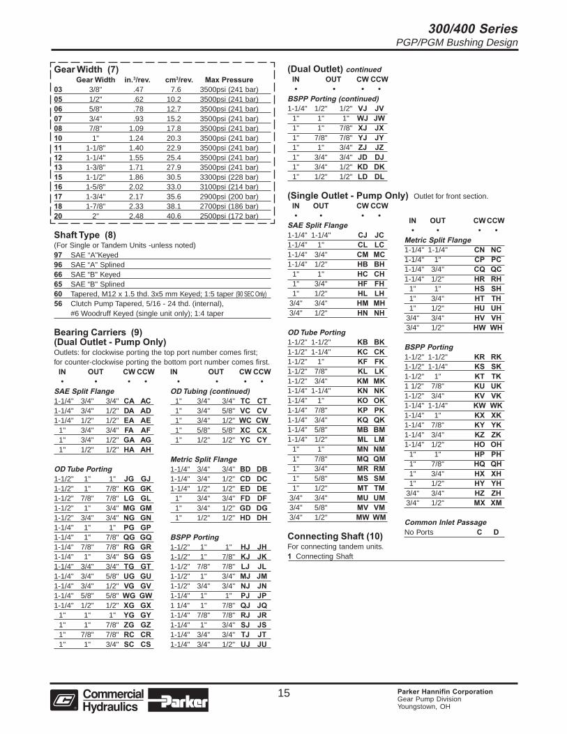
Gear Width (7)Gear Width in.3/rev. cm3/rev. Max Pressure
03 3/8" .47 7.6 3500psi (241 bar)05 1/2" .62 10.2 3500psi (241 bar)06 5/8" .78 12.7 3500psi (241 bar)07 3/4" .93 15.2 3500psi (241 bar)08 7/8" 1.09 17.8 3500psi (241 bar)10 1" 1.24 20.3 3500psi (241 bar)11 1-1/8" 1.40 22.9 3500psi (241 bar)12 1-1/4" 1.55 25.4 3500psi (241 bar)13 1-3/8" 1.71 27.9 3500psi (241 bar)15 1-1/2" 1.86 30.5 3300psi (228 bar)16 1-5/8" 2.02 33.0 3100psi (214 bar)17 1-3/4" 2.17 35.6 2900psi (200 bar)18 1-7/8" 2.33 38.1 2700psi (186 bar)20 2" 2.48 40.6 2500psi (172 bar)
Shaft Type (8)(For Single or Tandem Units -unless noted)97 SAE “A"Keyed96 SAE “A" Splined66 SAE “B" Keyed65 SAE “B" Splined60 Tapered, M12 x 1.5 thd. 3x5 mm Keyed; 1:5 taper (90 SEC Only)56 Clutch Pump Tapered, 5/16 - 24 thd. (internal),
#6 Woodruff Keyed (single unit only); 1:4 taper
Bearing Carriers (9)(Dual Outlet - Pump Only)Outlets: for clockwise porting the top port number comes first;for counter-clockwise porting the bottom port number comes first.
IN OUT CW CCW• • •
SAE Split Flange1-1/4" 3/4" 3/4" CA AC1-1/4" 3/4" 1/2" DA AD1-1/4" 1/2" 1/2" EA AE
1" 3/4" 3/4" FA AF1" 3/4" 1/2" GA AG1" 1/2" 1/2" HA AH
OD Tube Porting1-1/2" 1" 1" JG GJ1-1/2" 1" 7/8" KG GK1-1/2" 7/8" 7/8" LG GL1-1/2" 1" 3/4" MG GM1-1/2" 3/4" 3/4" NG GN1-1/4" 1" 1" PG GP1-1/4" 1" 7/8" QG GQ1-1/4" 7/8" 7/8" RG GR1-1/4" 1" 3/4" SG GS1-1/4" 3/4" 3/4" TG GT1-1/4" 3/4" 5/8" UG GU1-1/4" 3/4" 1/2" VG GV1-1/4" 5/8" 5/8" WG GW1-1/4" 1/2" 1/2" XG GX
1" 1" 1" YG GY1" 1" 7/8" ZG GZ1" 7/8" 7/8" RC CR1" 1" 3/4" SC CS
IN OUT CW CCW• • •
OD Tubing (continued)1" 3/4" 3/4" TC CT1" 3/4" 5/8" VC CV1" 3/4" 1/2" WC CW1" 5/8" 5/8" XC CX1" 1/2" 1/2" YC CY
Metric Split Flange1-1/4" 3/4" 3/4" BD DB1-1/4" 3/4" 1/2" CD DC1-1/4" 1/2" 1/2" ED DE
1" 3/4" 3/4" FD DF1" 3/4" 1/2" GD DG1" 1/2" 1/2" HD DH
BSPP Porting1-1/2" 1" 1" HJ JH1-1/2" 1" 7/8" KJ JK1-1/2" 7/8" 7/8" LJ JL1-1/2" 1" 3/4" MJ JM1-1/2" 3/4" 3/4" NJ JN1-1/4" 1" 1" PJ JP1 1/4" 1" 7/8" QJ JQ1-1/4" 7/8" 7/8" RJ JR1-1/4" 1" 3/4" SJ JS1-1/4" 3/4" 3/4" TJ JT1-1/4" 3/4" 1/2" UJ JU
(Dual Outlet) continuedIN OUT CW CCW• • •
BSPP Porting (continued)1-1/4" 1/2" 1/2" VJ JV
1" 1" 1" WJ JW1" 1" 7/8" XJ JX1" 7/8" 7/8" YJ JY1" 1" 3/4" ZJ JZ1" 3/4" 3/4" JD DJ1" 3/4" 1/2" KD DK1" 1/2" 1/2" LD DL
(Single Outlet - Pump Only) Outlet for front section.IN OUT CW CCW• • • •
SAE Split Flange1-1/4" 1-1/4" CJ JC1-1/4" 1" CL LC1-1/4" 3/4" CM MC1-1/4" 1/2" HB BH
1" 1" HC CH1" 3/4" HF FH1" 1/2" HL LH
3/4" 3/4" HM MH3/4" 1/2" HN NH
OD Tube Porting1-1/2" 1-1/2" KB BK1-1/2" 1-1/4" KC CK1-1/2" 1" KF FK1-1/2" 7/8" KL LK1-1/2" 3/4" KM MK1-1/4" 1-1/4" KN NK1-1/4" 1" KO OK1-1/4" 7/8" KP PK1-1/4" 3/4" KQ QK1-1/4" 5/8" MB BM1-1/4" 1/2" ML LM
1" 1" MN NM1" 7/8" MQ QM1" 3/4" MR RM1" 5/8" MS SM1" 1/2" MT TM
3/4" 3/4" MU UM3/4" 5/8" MV VM3/4" 1/2" MW WM
Connecting Shaft (10)For connecting tandem units.1 Connecting Shaft
IN OUT CW CCW• • • •
Metric Split Flange1-1/4" 1-1/4" CN NC1-1/4" 1" CP PC1-1/4" 3/4" CQ QC1-1/4" 1/2" HR RH
1" 1" HS SH1" 3/4" HT TH1" 1/2" HU UH
3/4" 3/4" HV VH3/4" 1/2" HW WH
BSPP Porting1-1/2" 1-1/2" KR RK1-1/2" 1-1/4" KS SK1-1/2" 1" KT TK1 1/2" 7/8" KU UK1-1/2" 3/4" KV VK1-1/4" 1-1/4" KW WK1-1/4" 1" KX XK1-1/4" 7/8" KY YK1-1/4" 3/4" KZ ZK1-1/4" 1/2" HO OH
1" 1" HP PH1" 7/8" HQ QH1" 3/4" HX XH1" 1/2" HY YH
3/4" 3/4" HZ ZH3/4" 1/2" MX XM
Common Inlet PassageNo Ports C D
••
•
300/400 SeriesPGP/PGM Bushing Design
16 Parker Hannifin CorporationGear Pump DivisionYoungstown, OH
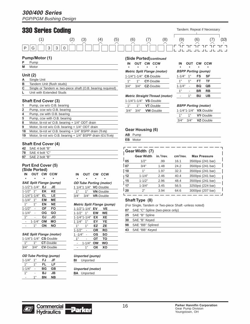
330 Series Coding
Pump/Motor (1)P PumpM Motor
Unit (2)A Single UnitB Tandem Unit (flush studs)C Single or Tandem w. two-piece shaft (O.B. bearing required)L Unit with Extended Studs
Shaft End Cover (3)1 Pump, cw w/o O.B. bearing2 Pump, ccw w/o O.B. bearing4 Pump, cw with O.B. bearing5 Pump, ccw with O.B. bearing8 Motor, bi-rot w/ O.B. bearing + 1/4" ODT drain9 Motor, bi-rot w/o O.B. bearing + 1/4" ODT drain18 Motor, bi-rot w/ O.B. bearing + 1/4" BSPP drain (78 only)19 Motor, bi-rot w/o O.B. bearing + 1/4" BSPP drain (42 & 78 only)
Shaft End Cover (4)42 SAE 4 bolt “B"78 SAE 4 bolt “C"97 SAE 2 bolt “B"
Port End Cover (5)(Side Ported)
IN OUT CW CCW• • • •
SAE Split Flange (pump)1-1/2"1-1/4" EJ JE1-1/2" 1" EK KE1-1/4"1-1/4" EL LE1-1/4" 1" EM ME
1" 1" EN NE1-1/2" - OF FO1-1/4" - OG GO
1" - OJ JO- 1-1/4" OM MO- 1" ON NO
SAE Split Flange (motor)1-1/4"1-1/4" CS-Double
1" 1" CT-Double3/4" 3/4" CV-Double
OD Tube Porting (pump)1-1/4" 1" FJ JF
1" 1" FL LF1-1/4" - BG GB
1" - BJ JB- 1" BN NB
IN OUT CW CCW• • • •
OD Tube Porting (motor)1 1/4"1 1/4" VC-Double
1" 1" VN-Double3/4" 3/4" VR-Double
Metric Split Flange (pump)1-1/2"1-1/4" EV VE1-1/2" 1" EW WE1-1/4"1-1/4" EX XE1 1/4" 1" EY YE
1" 1" EZ ZE1-1/2" - OR RO1 -1/4" - OS SO
1" - OT TO- 1-1/4" OW WO- 1" OX XO
Unported (pump)BI Unported
Unported (motor)BA Unported
(Side Ported)continuedIN OUT CW CCW• • • •
Metric Split Flange (motor)1-1/4"1-1/4" CX-Double
1" 1" CY-Double
3/4" 3/4" CZ-Double
Metric Straight Thread (motor)1-1/4"1-1/4" VS-Double
1" 1" VT-Double
3/4" 3/4" VW-Double
IN OUT CW CCW• • • •
BSPP Porting (pump)1-1/4" 1" FS SF
1" 1" FT TF1-1/4" - BQ QB
1" - BR RB- 1" BU UB
BSPP Porting (motor)1-1/4"1-1/4" VX-Double
1" 1" VY-Double
3/4" 3/4" VZ-Double
Gear Housing (6)AB Pump
EB Motor
Gear Width (7)Gear Width in.3/rev. cm3/rev. Max Pressure
05 1/2" .99 16.1 3500psi (241 bar)
07 3/4" 1.48 24.2 3500psi (241 bar)
10 1" 1.97 32.3 3500psi (241 bar)
12 1-1/4" 2.46 40.4 3500psi (241 bar)
15 1-1/2" 2.96 48.4 3500psi (241 bar)
17 1-3/4" 3.45 56.5 3250psi (224 bar)
20 2" 3.94 64.6 3000psi (207 bar)
Shaft Type (8)(For Single, Tandem or Two-piece Shaft -unless noted)
07 SAE “C" Spline (two-piece only)
25 SAE “B" Spline
30 SAE “B" Keyed
98 SAE “BB" Splined
43 SAE “BB" Keyed
(4)(2) (5) (6) (7) (8) (9) (6) (7) (10)
Tandem: Repeat if Necessary
(3)
3 3 0
(1)
GP
300/400 SeriesPGP/PGM Bushing Design
17 Parker Hannifin CorporationGear Pump DivisionYoungstown, OH
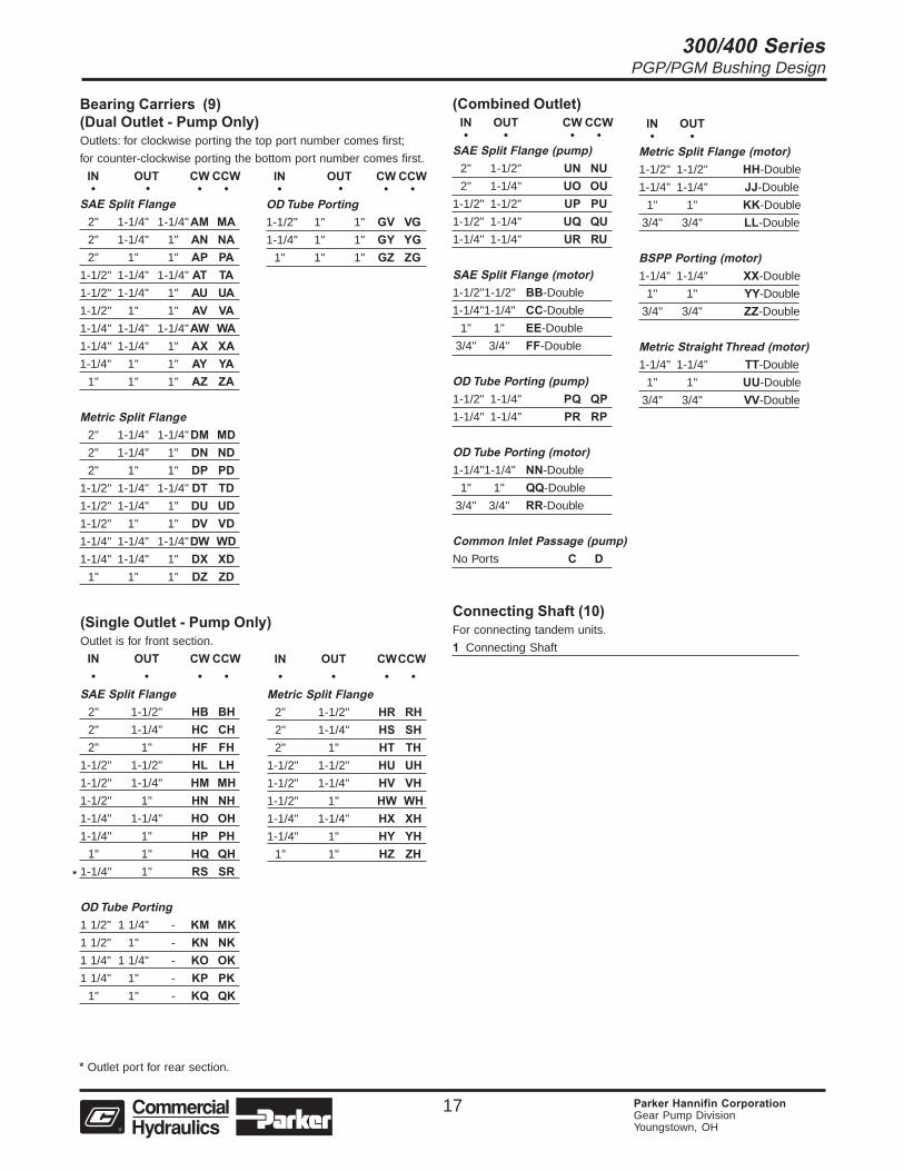
Bearing Carriers (9)(Dual Outlet - Pump Only)Outlets: for clockwise porting the top port number comes first;
for counter-clockwise porting the bottom port number comes first.
IN OUT CW CCW• • •
SAE Split Flange2" 1-1/4" 1-1/4"AM MA2" 1-1/4" 1" AN NA2" 1" 1" AP PA
1-1/2" 1-1/4" 1-1/4" AT TA1-1/2" 1-1/4" 1" AU UA1-1/2" 1" 1" AV VA1-1/4" 1-1/4" 1-1/4"AW WA1-1/4" 1-1/4" 1" AX XA1-1/4" 1" 1" AY YA
1" 1" 1" AZ ZA
Metric Split Flange2" 1-1/4" 1-1/4"DM MD2" 1-1/4" 1" DN ND2" 1" 1" DP PD
1-1/2" 1-1/4" 1-1/4" DT TD1-1/2" 1-1/4" 1" DU UD1-1/2" 1" 1" DV VD1-1/4" 1-1/4" 1-1/4"DW WD1-1/4" 1-1/4" 1" DX XD
1" 1" 1" DZ ZD
IN OUT CW CCW• • •
OD Tube Porting1-1/2" 1" 1" GV VG1-1/4" 1" 1" GY YG
1" 1" 1" GZ ZG
(Combined Outlet)IN OUT CW CCW• • • •
SAE Split Flange (pump)2" 1-1/2" UN NU2" 1-1/4" UO OU
1-1/2" 1-1/2" UP PU1-1/2" 1-1/4" UQ QU1-1/4" 1-1/4" UR RU
SAE Split Flange (motor)1-1/2"1-1/2" BB-Double
1-1/4"1-1/4" CC-Double
1" 1" EE-Double
3/4" 3/4" FF-Double
OD Tube Porting (pump)1-1/2" 1-1/4" PQ QP1-1/4" 1-1/4" PR RP
OD Tube Porting (motor)1-1/4"1-1/4" NN-Double
1" 1" QQ-Double
3/4" 3/4" RR-Double
Common Inlet Passage (pump)No Ports C D
Connecting Shaft (10)For connecting tandem units.
1 Connecting Shaft
IN OUT• •
Metric Split Flange (motor)1-1/2" 1-1/2" HH-Double
1-1/4" 1-1/4" JJ-Double
1" 1" KK-Double
3/4" 3/4" LL-Double
BSPP Porting (motor)1-1/4" 1-1/4" XX-Double
1" 1" YY-Double
3/4" 3/4" ZZ-Double
Metric Straight Thread (motor)1-1/4" 1-1/4" TT-Double
1" 1" UU-Double
3/4" 3/4" VV-Double
*
* Outlet port for rear section.
(Single Outlet - Pump Only)Outlet is for front section.
IN OUT CW CCW• • • •
SAE Split Flange2" 1-1/2" HB BH2" 1-1/4" HC CH2" 1" HF FH
1-1/2" 1-1/2" HL LH1-1/2" 1-1/4" HM MH1-1/2" 1" HN NH1-1/4" 1-1/4" HO OH1-1/4" 1" HP PH
1" 1" HQ QH1-1/4" 1" RS SR
OD Tube Porting1 1/2" 1 1/4" - KM MK1 1/2" 1" - KN NK1 1/4" 1 1/4" - KO OK1 1/4" 1" - KP PK
1" 1" - KQ QK
IN OUT CWCCW• • • •
Metric Split Flange2" 1-1/2" HR RH2" 1-1/4" HS SH2" 1" HT TH
1-1/2" 1-1/2" HU UH1-1/2" 1-1/4" HV VH1-1/2" 1" HW WH1-1/4" 1-1/4" HX XH1-1/4" 1" HY YH
1" 1" HZ ZH
• •

300/400 SeriesPGP/PGM Bushing Design
18 Parker Hannifin CorporationGear Pump DivisionYoungstown, OH
350 Series Coding
Pump/Motor (1)P PumpM Motor
Unit (2)A Single UnitB Tandem Unit (flush studs)C Single or Tandem w. two-piece shaft (O.B. bearing required)L Unit with Extended Studs
Shaft End Cover (3)1 Pump, cw w/o O.B. bearing2 Pump, ccw w/o O.B. bearing4 Pump, cw with O.B. bearing5 Pump, ccw with O.B. bearing8 Motor, bi-rot w/ O.B. bearing + 1/4" ODT drain9 Motor, bi-rot w/o O.B. bearing + 1/4" ODT drain18 Motor, bi-rot w/ O.B. bearing + 1/4" BSPP drain (78 Only)19 Motor, bi-rot w/o O.B. bearing + 1/4" BSPP drain (78 Only)
Shaft End Cover (4)42 SAE 4 bolt “B"46 SAE 2/4 bolt “B"62 “ZF" 4 bolt (462 only) - 80 mm pilot, 80x80 mm78 SAE 4 bolt “C"97 SAE 2 bolt “B"98 SAE 2 bolt “C"
Port End Cover (5)(Side Ported)
IN OUT CW CCW• • • •
SAE Split Flange (pump)2" 1-1/2" EC CE2" 1-1/4" EF FE2" 1" EG GE
1-1/2"1-1/2" EH HE1-1/2"1-1/4" EJ JE1-1/2" 1" EK KE1-1/4"1-1/4" EL LE1-1/4" 1" EM ME
1" 1" EN NE2" - OE EO
1-1/2" - OF FO1-1/4" - OG GO
1" - OJ JO- 1-1/2" OL LO- 1-1/4" OM MO- 1" ON NO
SAE Split Flange (motor)1-1/2"1-1/2" CR-Double1-1/4"1-1/4" CS-Double
1" 1" CT-Double3/4" 3/4" CV-Double
IN OUT CW CCW• • • •
OD Tube Porting (pump)1-1/2"1-1/4" FB BF1-1/2" 1" FC CF1-1/4"1-1/4" FG GF1-1/4" 1" FJ JF
1" 1" FL LF1-1/2" - BC CB1-1/4" - BG GB
1" - BJ JB- 1-1/4" BL LB- 1" BN NB
OD Tube Porting (motor)1-1/4"1-1/4" VC-Double
1" 1" VN-Double3/4" 3/4" VR-Double
Unported (pump)Unported BI IB
Unported (motor)BA Unported
(Side Ported)continuedIN OUT CW CCW• • • •
Metric Split Flange (pump)2" 1-1/2" ER RE2" 1-1/4" ES SE2" 1" ET TE
1-1/2"1-1/2" EU UE1-1/2"1-1/4" EV VE1-1/2" 1" EW WE1-1/4"1-1/4" EX XE1-1/4" 1" EY YE
1" 1" EZ ZE2" - OP PO
1-1/2" - OR RO1-1/4" - OS SO
1" - OT TO- 1-1/2" OV VO- 1-1/4" OW WO- 1" OX XO
Metric Split Flange (motor)1-1/2"1-1/2" CW-Double1-1/4"1-1/4" CX-Double
1" 1" CY-Double3/4" 3/4" CZ-Double
IN OUT CW CCW• • • •
Metric Straight Thread (motor)1-1/4"1-1/4" VS-Double
1" 1" VT-Double3/4" 3/4" VW-Double
BSPP Porting (pump)1-1/2"1-1/4" FN NF1-1/2" 1" FP PF1-1/4"1-1/4" FR RF1-1/4" 1" FS SF
1" 1" FT TF1-1/2" - BP PB1-1/4" - BQ QB
1" - BR RB- 1-1/4" BT TB- 1" BU UB
BSPP Porting (motor)1-1/4"1-1/4" VX-Double
1" 1" VY-Double3/4" 3/4" VZ-Double
Gear Housing (6)AB Pump
EB Motor
Gear Width (7)Gear Width in.3/rev. cm3/rev. Max Pressure
05 1/2" 1.28 20.9 3500psi (241 bar)
07 3/4" 1.91 31.3 3500psi (241 bar)
10 1" 2.55 41.8 3500psi (241 bar)
12 1-1/4" 3.19 52.2 3500psi (241 bar)
15 1-1/2" 3.83 62.7 3500psi (241 bar)
17 1-3/4" 4.46 73.1 3250psi (224 bar)
20 2" 5.10 83.6 3000psi (207 bar)
22 2-1/4" 5.74 94.0 2750psi (190 bar)
25 2-1/2" 6.38 104.5 2500psi (172 bar)
(4)(2) (5) (6) (7) (8) (9) (6) (7) (10)
Tandem: Repeat if Necessary
(3)
3 5 0
(1)
GP

300/400 SeriesPGP/PGM Bushing Design
19 Parker Hannifin CorporationGear Pump DivisionYoungstown, OH
Shaft Type (8)(For Single, Tandem or Two-piece Shaft -unless noted)06 88X32X36 DIN 5462 Spline (two-piece only)07 SAE “C" Spline11 SAE “C" Keyed25 SAE “B" Spline43 SAE “BB" Keyed73 SAE “C" Keyed Long (single and two-piece only)98 SAE “BB" Splined (tandem only)
Bearing Carriers (9)(Dual Outlet - Pump Only)Outlets: for clockwise porting the top port number comes first;for counter-clockwise porting the bottom port number comes first.
IN OUT CW CCW• • •
SAE Split Flange2-1/2" 1-1/4" 1-1/4" AF FA2-1/2" 1-1/4" 1" AG GA2-1/2" 1" 1" AH HA
2" 1-1/4" 1-1/4"AM MA2" 1-1/4" 1" AN NA2" 1" 1" AP PA
1-1/2" 1-1/4" 1-1/4" AT TA1-1/2" 1-1/4" 1" AU UA1-1/2" 1" 1" AV VA1-1/4" 1-1/4" 1-1/4"AW WA1-1/4" 1-1/4" 1" AX XA1-1/4" 1" 1" AY YA
1" 1" 1" AZ ZA
Metric Split Flange2" 1-1/4" 1-1/4"DM MD2" 1-1/4" 1" DN ND2" 1" 1" DP PD
1-1/2" 1-1/4" 1-1/4" DT TD1-1/2" 1-1/4" 1" DU UD1-1/2" 1" 1" DV VD1-1/4" 1-1/4" 1-1/4"DW WD1-1/4" 1-1/4" 1" DX XD1-1/4" 1" 1" DY YD
1" 1" 1" DZ ZD
IN OUT CW CCW• • •
OD Tube Porting2" 1-1/4" 1-1/4"GM MG2" 1-1/4" 1" GN NG2" 1" 1" GP PG
1-1/2" 1-1/4" 1-1/4" GT TG1-1/2" 1-1/4" 1" GU UG1-1/2" 1" 1" GV VG1-1/4" 1-1/4" 1-1/4"GW WG1-1/4" 1-1/4" 1" GX XG1-1/4" 1" 1" GY YG
1" 1" 1" GZ ZG
(Combined Outlet)IN OUT CW CCW• • • •
SAE Split Flange (pump)2" 1-1/2" UN NU2" 1-1/4" UO OU
1-1/2" 1-1/2" UP PU1-1/2" 1-1/4" UQ QU1-1/4" 1-1/4" UR RU
SAE Split Flange (motor)2" 2" AA-Double
1-1/2"1-1/2" BB-Double1-1/4"1-1/4" CC-Double
1" 1" EE-Double3/4" 3/4" FF-Double
OD Tube Porting (pump)2" 1-1/2" PE EP2" 1-1/4" PM MP
1-1/2" 1-1/2" PN NP1-1/2" 1-1/4" PQ QP1-1/4" 1-1/4" PR RP
OD Tube Porting (motor)1-1/2"1-1/2" MM-Double1-1/4"1-1/4" NN-Double
1" 1" QQ-Double3/4" 3/4" RR-Double
Common Inlet PassageNo Ports C D
Connecting Shaft (10)For connecting tandem units.1 Connecting Shaft
IN OUT• •
Metric Split Flange (motor)2" 2" GG-Double
1-1/2" 1-1/2" HH-Double1-1/4" 1-1/4" JJ-Double
1" 1" KK-Double3/4" 3/4" LL-Double
BSPP Porting (motor)1-1/2" 1-1/2" WW-Double1-1/4" 1-1/4" XX-Double
1" 1" YY-Double3/4" 3/4" ZZ-Double
Metric Straight Thread (motor)1-1/2" 1-1/2" SS-Double1-1/4" 1-1/4" TT-Double
1" 1" UU-Double3/4" 3/4" VV-Double
(Single Outlet - Pump Only) Outlet for front section.IN OUT CW CCW
• • • •SAE Split Flange
2" 1-1/2" HB BH2" 1-1/4" HC CH2" 1" HF FH
1-1/2" 1-1/2" HL LH1-1/2" 1-1/4" HM MH1-1/2" 1" HN NH1-1/4" 1-1/4" HO OH1-1/4" 1" HP PH
1" 1" HQ QH1-1/4" 1" RS SR
IN OUT CWCCW• • • •
OD Tube Porting2" 1-1/2" KB BK2" 1-1/4" KC CK2" 1" KF FK
1-1/2" 1-1/2" KL LK1-1/2" 1-1/4" KM MK1-1/2" 1" KN NK1-1/4" 1-1/4" KO OK1-1/4" 1" KP PK
1" 1" KQ QK
(Single Outlet)IN OUT CW CCW• • • •
BSPP Porting2" 1-1/2" KR RK2" 1-1/4" KS SK2" 1" KT TK
1-1/2" 1-1/2" KU UK1-1/2" 1-1/4" KV VK1-1/2" 1" KW WK1-1/4" 1-1/4" KX XK1-1/4" 1" KY YK
1" 1" KZ ZK
*
* Outlet port for rear section.
• •
300/400 SeriesPGP/PGM Bushing Design
20 Parker Hannifin CorporationGear Pump DivisionYoungstown, OH
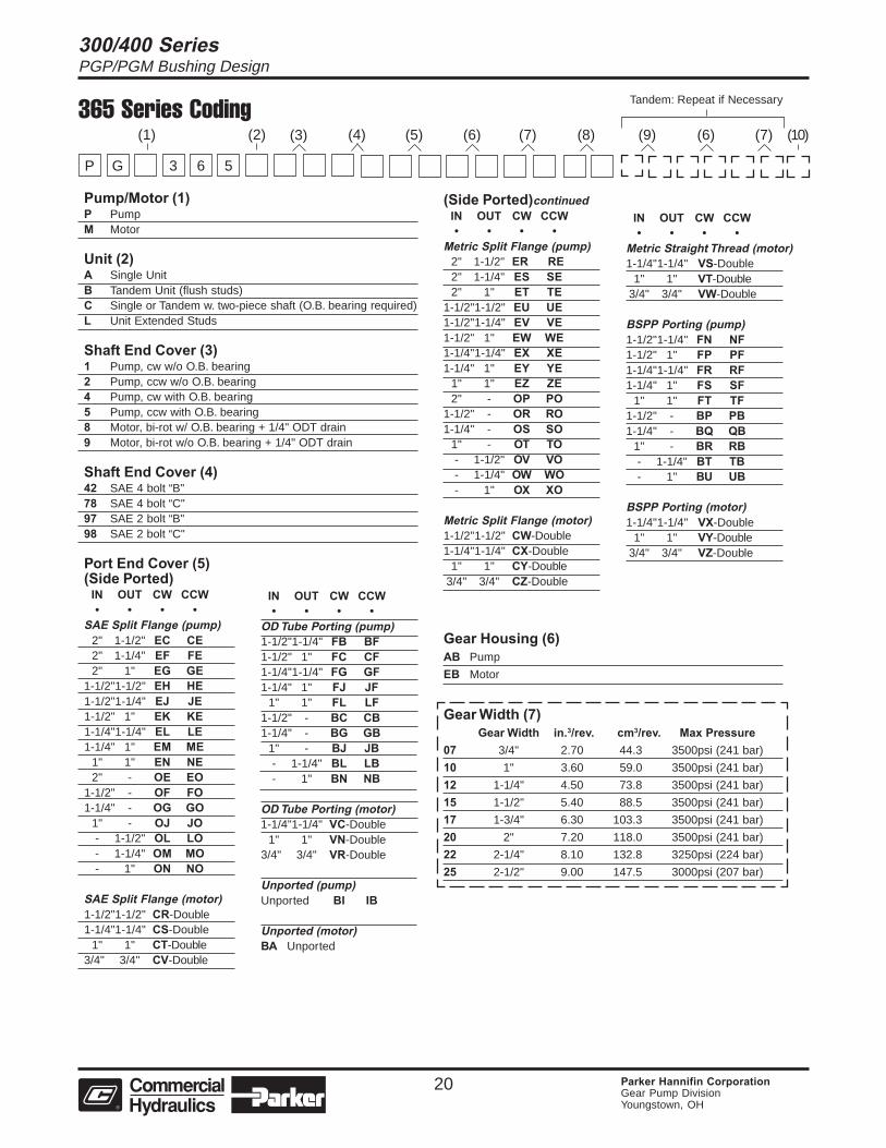
365 Series Coding
Pump/Motor (1)P PumpM Motor
Unit (2)A Single UnitB Tandem Unit (flush studs)C Single or Tandem w. two-piece shaft (O.B. bearing required)L Unit Extended Studs
Shaft End Cover (3)1 Pump, cw w/o O.B. bearing2 Pump, ccw w/o O.B. bearing4 Pump, cw with O.B. bearing5 Pump, ccw with O.B. bearing8 Motor, bi-rot w/ O.B. bearing + 1/4" ODT drain9 Motor, bi-rot w/o O.B. bearing + 1/4" ODT drain
Shaft End Cover (4)42 SAE 4 bolt “B"78 SAE 4 bolt “C"97 SAE 2 bolt “B"98 SAE 2 bolt “C"
Port End Cover (5)(Side Ported)
IN OUT CW CCW• • • •
SAE Split Flange (pump)2" 1-1/2" EC CE2" 1-1/4" EF FE2" 1" EG GE
1-1/2"1-1/2" EH HE1-1/2"1-1/4" EJ JE1-1/2" 1" EK KE1-1/4"1-1/4" EL LE1-1/4" 1" EM ME
1" 1" EN NE2" - OE EO
1-1/2" - OF FO1-1/4" - OG GO
1" - OJ JO- 1-1/2" OL LO- 1-1/4" OM MO- 1" ON NO
SAE Split Flange (motor)1-1/2"1-1/2" CR-Double1-1/4"1-1/4" CS-Double
1" 1" CT-Double3/4" 3/4" CV-Double
IN OUT CW CCW• • • •
OD Tube Porting (pump)1-1/2"1-1/4" FB BF1-1/2" 1" FC CF1-1/4"1-1/4" FG GF1-1/4" 1" FJ JF
1" 1" FL LF1-1/2" - BC CB1-1/4" - BG GB
1" - BJ JB- 1-1/4" BL LB- 1" BN NB
OD Tube Porting (motor)1-1/4"1-1/4" VC-Double
1" 1" VN-Double3/4" 3/4" VR-Double
Unported (pump)Unported BI IB
Unported (motor)BA Unported
(Side Ported)continuedIN OUT CW CCW• • • •
Metric Split Flange (pump)2" 1-1/2" ER RE2" 1-1/4" ES SE2" 1" ET TE
1-1/2"1-1/2" EU UE1-1/2"1-1/4" EV VE1-1/2" 1" EW WE1-1/4"1-1/4" EX XE1-1/4" 1" EY YE
1" 1" EZ ZE2" - OP PO
1-1/2" - OR RO1-1/4" - OS SO
1" - OT TO- 1-1/2" OV VO- 1-1/4" OW WO- 1" OX XO
Metric Split Flange (motor)1-1/2"1-1/2" CW-Double1-1/4"1-1/4" CX-Double
1" 1" CY-Double3/4" 3/4" CZ-Double
IN OUT CW CCW• • • •
Metric Straight Thread (motor)1-1/4"1-1/4" VS-Double
1" 1" VT-Double3/4" 3/4" VW-Double
BSPP Porting (pump)1-1/2"1-1/4" FN NF1-1/2" 1" FP PF1-1/4"1-1/4" FR RF1-1/4" 1" FS SF
1" 1" FT TF1-1/2" - BP PB1-1/4" - BQ QB
1" - BR RB- 1-1/4" BT TB- 1" BU UB
BSPP Porting (motor)1-1/4"1-1/4" VX-Double
1" 1" VY-Double3/4" 3/4" VZ-Double
Gear Housing (6)AB Pump
EB Motor
Gear Width (7)Gear Width in.3/rev. cm3/rev. Max Pressure
07 3/4" 2.70 44.3 3500psi (241 bar)
10 1" 3.60 59.0 3500psi (241 bar)
12 1-1/4" 4.50 73.8 3500psi (241 bar)
15 1-1/2" 5.40 88.5 3500psi (241 bar)
17 1-3/4" 6.30 103.3 3500psi (241 bar)
20 2" 7.20 118.0 3500psi (241 bar)
22 2-1/4" 8.10 132.8 3250psi (224 bar)
25 2-1/2" 9.00 147.5 3000psi (207 bar)
(4)(2) (5) (6) (7) (8) (9) (6) (7) (10)
Tandem: Repeat if Necessary
(3)
3 6 5
(1)
GP
300/400 SeriesPGP/PGM Bushing Design
21 Parker Hannifin CorporationGear Pump DivisionYoungstown, OH
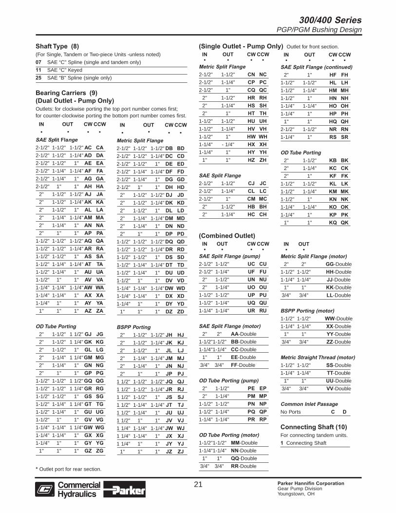
Shaft Type (8)(For Single, Tandem or Two-piece Units -unless noted)
07 SAE “C" Spline (single and tandem only)
11 SAE “C" Keyed
25 SAE “B" Spline (single only)
Bearing Carriers (9)(Dual Outlet - Pump Only)Outlets: for clockwise porting the top port number comes first;for counter-clockwise porting the bottom port number comes first.
IN OUT CW CCW• • •
SAE Split Flange2-1/2" 1-1/2" 1-1/2" AC CA2-1/2" 1-1/2" 1-1/4" AD DA2-1/2" 1-1/2" 1" AE EA2-1/2" 1-1/4" 1-1/4" AF FA2-1/2" 1-1/4" 1" AG GA2-1/2" 1" 1" AH HA
2" 1-1/2" 1-1/2" AJ JA2" 1-1/2" 1-1/4" AK KA2" 1-1/2" 1" AL LA2" 1-1/4" 1-1/4"AM MA2" 1-1/4" 1" AN NA2" 1" 1" AP PA
1-1/2" 1-1/2" 1-1/2" AQ QA1-1/2" 1-1/2" 1-1/4" AR RA1-1/2" 1-1/2" 1" AS SA1-1/2" 1-1/4" 1-1/4" AT TA1-1/2" 1-1/4" 1" AU UA1-1/2" 1" 1" AV VA1-1/4" 1-1/4" 1-1/4"AW WA1-1/4" 1-1/4" 1" AX XA1-1/4" 1" 1" AY YA
1" 1" 1" AZ ZA
OD Tube Porting2" 1-1/2" 1 1/2" GJ JG2" 1-1/2" 1 1/4" GK KG2" 1-1/2" 1" GL LG2" 1-1/4" 1 1/4"GM MG2" 1-1/4" 1" GN NG2" 1" 1" GP PG
1-1/2" 1-1/2" 1 1/2" GQ QG1-1/2" 1-1/2" 1 1/4" GR RG1-1/2" 1-1/2" 1" GS SG1-1/2" 1-1/4" 1 1/4" GT TG1-1/2" 1-1/4" 1" GU UG1-1/2" 1" 1" GV VG1-1/4" 1-1/4" 1 1/4"GW WG1-1/4" 1-1/4" 1" GX XG1-1/4" 1" 1" GY YG
1" 1" 1" GZ ZG
(Combined Outlet)IN OUT CW CCW• • • •
SAE Split Flange (pump)2-1/2" 1-1/2" UC CU2-1/2" 1-1/4" UF FU
2" 1-1/2" UN NU2" 1-1/4" UO OU
1-1/2" 1-1/2" UP PU1-1/2" 1-1/4" UQ QU1-1/4" 1-1/4" UR RU
SAE Split Flange (motor)2" 2" AA-Double
1-1/2"1-1/2" BB-Double
1-1/4"1-1/4" CC-Double
1" 1" EE-Double
3/4" 3/4" FF-Double
OD Tube Porting (pump)2" 1-1/2" PE EP2" 1-1/4" PM MP
1-1/2" 1-1/2" PN NP1-1/2" 1-1/4" PQ QP1-1/4" 1-1/4" PR RP
OD Tube Porting (motor)1-1/2"1-1/2" MM-Double
1-1/4"1-1/4" NN-Double
1" 1" QQ-Double
3/4" 3/4" RR-Double
IN OUT• •
Metric Split Flange (motor)2" 2" GG-Double
1-1/2" 1-1/2" HH-Double
1-1/4" 1-1/4" JJ-Double
1" 1" KK-Double
3/4" 3/4" LL-Double
BSPP Porting (motor)1-1/2" 1-1/2" WW-Double
1-1/4" 1-1/4" XX-Double
1" 1" YY-Double
3/4" 3/4" ZZ-Double
Metric Straight Thread (motor)1-1/2" 1-1/2" SS-Double
1-1/4" 1-1/4" TT-Double
1" 1" UU-Double
3/4" 3/4" VV-Double
Common Inlet PassageNo Ports C D
Connecting Shaft (10)For connecting tandem units.
1 Connecting Shaft
(Single Outlet - Pump Only) Outlet for front section.
IN OUT CW CCW• • • •
Metric Split Flange2-1/2" 1-1/2" CN NC2-1/2" 1-1/4" CP PC2-1/2" 1" CQ QC
2" 1-1/2" HR RH2" 1-1/4" HS SH2" 1" HT TH
1-1/2" 1-1/2" HU UH1-1/2" 1-1/4" HV VH1-1/2" 1" HW WH1-1/4" - 1/4" HX XH1-1/4" 1" HY YH
1" 1" HZ ZH
SAE Split Flange2-1/2" 1-1/2" CJ JC2-1/2" 1-1/4" CL LC2-1/2" 1" CM MC
2" 1-1/2" HB BH2" 1-1/4" HC CH
IN OUT CW CCW• • • •
SAE Split Flange (continued)2" 1" HF FH
1-1/2" 1-1/2" HL LH1-1/2" 1-1/4" HM MH1-1/2" 1" HN NH1-1/4" 1-1/4" HO OH1-1/4" 1" HP PH
1" 1" HQ QH2-1/2" 1-1/2" NR RN1-1/4" 1" RS SR
OD Tube Porting2" 1-1/2" KB BK2" 1-1/4" KC CK2" 1" KF FK
1-1/2" 1-1/2" KL LK1-1/2" 1-1/4" KM MK1-1/2" 1" KN NK1-1/4" 1-1/4" KO OK1-1/4" 1" KP PK
1" 1" KQ QK
IN OUT CW CCW• • •
Metric Split Flange2-1/2" 1-1/2" 1-1/2" DB BD2-1/2" 1-1/2" 1-1/4" DC CD2-1/2" 1-1/2" 1" DE ED2-1/2" 1-1/4" 1-1/4" DF FD2-1/2" 1-1/4" 1" DG GD2-1/2" 1" 1" DH HD
2" 1-1/2" 1-1/2" DJ JD2" 1-1/2" 1-1/4" DK KD2" 1-1/2" 1" DL LD2" 1-1/4" 1-1/4"DM MD2" 1-1/4" 1" DN ND2" 1" 1" DP PD
1-1/2" 1-1/2" 1-1/2" DQ QD1-1/2" 1-1/2" 1-1/4" DR RD1-1/2" 1-1/2" 1" DS SD1-1/2" 1-1/4" 1-1/4" DT TD1-1/2" 1-1/4" 1" DU UD1-1/2" 1" 1" DV VD1-1/4" 1-1/4" 1-1/4"DW WD1-1/4" 1-1/4" 1" DX XD1-1/4" 1" 1" DY YD
1" 1" 1" DZ ZD
BSPP Porting2" 1-1/2" 1-1/2" JH HJ2" 1-1/2" 1-1/4" JK KJ2" 1-1/2" 1" JL LJ2" 1-1/4" 1-1/4" JM MJ2" 1-1/4" 1" JN NJ2" 1" 1" JP PJ
1 1/2" 1-1/2" 1-1/2" JQ QJ1 1/2" 1-1/2" 1-1/4" JR RJ1 1/2" 1-1/2" 1" JS SJ1 1/2" 1-1/4" 1-1/4" JT TJ1 1/2" 1-1/4" 1" JU UJ1 1/2" 1" 1" JV VJ1 1/4" 1-1/4" 1-1/4" JW WJ1 1/4" 1-1/4" 1" JX XJ1 1/4" 1" 1" JY YJ
1" 1" 1" JZ ZJ
* Outlet port for rear section.
• •

300/400 SeriesPGP/PGM Bushing Design
22 Parker Hannifin CorporationGear Pump DivisionYoungstown, OH
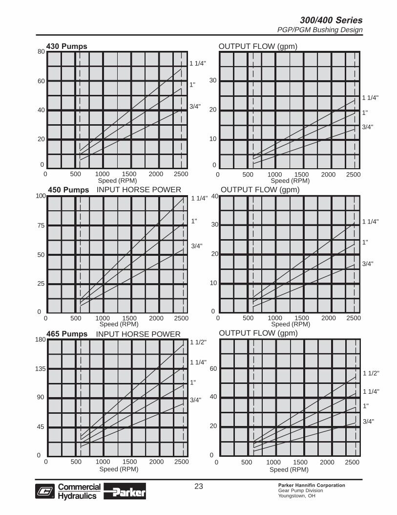
400 Series PumpsThe P400 series of high pressure, fixed displacementgear pumps are available in single and multipleassemblies. These units are rated for service up to4500 psi. They’re available in three models offeringyou a displacement range from 1.5 to 5.5 CIR.
These units are cast from high-strength iron whichprovides the structural integrity needed at highpressures. Gear widths have been selected to keepshaft deflections and bearing loads within acceptabledesign limits. Body seals have been strengthenedand the fastener pre-load increased to assurereliability under high pressure conditions.
A wide variety of SAE B and C mounting flanges anddrive shaft configurations are available. Porting isthrough SAE split flange or “O" ring fitting. Specialhardened steel alloy gears with integral drive shaftrun between pressure-balanced, bronze wear platesto make these rugged pumps highly efficient. Longshaft journals provide superior bearing surfaces andadd to long service life.
Pumps can be assembled for rotation in eitherdirection.
Displacement per inch of gear430 1.97 CIR450 2.55 CIR465 3.60 CIR
Performance DataThe performance data shown on the adjacent pageare the average results based on a series of labora-tory tests of production units and are not necessarilyrepresentative of any one unit. Tests were run at4500 psi with the oil reservoir temperature at 180° Fand viscosity of 150 SUS @ 100.
Oil RecommendationsThe pumps work well on most good hydraulic oils aswell as synthetic and fire resistant fluids. Pleasecheck with our product support department beforeusing any fire resistant or non-petroleum based fluid.Some of these products require special seals.
Viscosity – 50 SUS min. @ operating temperature 7500 SUS max. @ starting temperature
Viscosity index – 90 minimumAnaline point – 175 minimumAdditives – Foam depressant
Rust inhibitorsMaximum recommended system operatingtemperature is 180° F or 83° C.
Dimensional DataSingle Units
Multiple Units
430
450
465
6.78 5.88 9.88 + GW5.38 + GW
172.2 149.3 250.9 + GW136.7 + GW
7.68 6.00 10.25 + GW5.75 + GW
195.1 152.4 254.6 + GW146.8 + GW
8.38 7.25 11.38 + GW6.25 + GW
212.8 184.1 289.0 + GW158.7 + GW
Inches
MM
Inches
MM
Inches
MM
Model A B C D
430
450
465
6.88 5.88 6.19 + GW4.94 + GW
174.7 149.3 157.2 + GW125.5 + GW
7.12 6.00 7.06 + GW5.56 + GW
108.8 152.4 179.3 + GW141.2 + GW
7.38 7.25 7.31 + GW5.81 + GW
187.4 184.1 185.7 + GW147.6 + GW
Inches
MM
Inches
MM
Inches
MM
Model A B C D
300/400 SeriesPGP/PGM Bushing Design
23 Parker Hannifin CorporationGear Pump DivisionYoungstown, OH
430 Pumps OUTPUT FLOW (gpm)
0
0 500 1000 1500 2000 2500
20
40
60
80
1 1/4"
1"
3/4"
Speed (RPM)
0
0 500 1000 1500 2000 2500
1 1/4"
1"
3/4"
10
20
30
Speed (RPM)
INPUT HORSE POWER465 Pumps
0 500 1000 1500 2000 2500
1 1/2"
1 1/4"
1"
3/4"
0
45
90
135
Speed (RPM)
180 OUTPUT FLOW (gpm)
0 500 1000 1500 2000 2500
1 1/2"
1 1/4"
1"
3/4"
0
20
40
60
Speed (RPM)
OUTPUT FLOW (gpm)
0 500 1000 1500 2000 2500
1 1/4"
1"
3/4"
0
10
20
30
40
Speed (RPM)
450 Pumps INPUT HORSE POWER
0 500 1000 1500 2000 2500
25
50
75
100
0
Speed (RPM)
1 1/4"
1"
3/4"
300/400 SeriesPGP/PGM Bushing Design
24 Parker Hannifin CorporationGear Pump DivisionYoungstown, OH
Special Assemblies for Gear Pumps and MotorsContact Product Support for more information.
We became the market leading manufacturer of hydraulic gear pumps for mobile equipment by anticipat-ing customer needs and developing engineering solutions to meet them. While we offer a broad range ofstandard gear pumps and motors for most applications, we recognize that standard equipment may not alwaysbe the best solution. We are always ready and able to discuss special applications and provide practical, cost-effective, well-engineered solutions to your special hydraulic system needs. Here are a few examples of ourengineering and manufacturing skills.
315 Series - Special Assemblies• P315/M315 gears with various drive shafts• P315 port end cover with built-in relief valve Tandem use only - no inlet port available• P315 port end cover with side ports up to 1-I/2" S.F. inlet• P315 port end cover with integral priority valve Built-in relief valve on primary circuit• Clutch pump mount model available
330 Series - Special Assemblies• P330 dual outlet pump bearing carrier that will accept a 2-1/2" S.F. inlet port• P330/M330 gears with optional number of gear teeth (10 tooth gears are standard; 13 tooth gears are optional)• P330/M330 gears with various drive shafts and gear widths• P330/315 piggyback• P330 port end cover with side ports up to 2" S.F. inlet• Narrow P330 dual rotation port end cover that accepts side and/or rear ports• Narrow P330 port end cover that accepts side and/or rear ports• P330 port end cover that accepts rear threaded ports• P330 port end cover with integral priority valve No relief valve on primary circuit• P330 pad mount shaft end cover with two drive shafts• P330 SAE "B" 2 bolt short shaft end cover• FD330 flow divider assemblies
350 Series - Special Assemblies• P350/M350 gears with optional number of gear teeth (10 tooth gears are standard; 13 tooth gears are optional)• P350/M350 gears with various drive shafts and gear widths• P350/315 piggyback• P350 add-a-pump port end cover with the ability to mount any pump that has an SAE "A" or "B" 2 bolt mounting flange and SAE "A" or "B" splined drive shaft• P350 port end cover that is shorter and narrower than standard P350 PEC. Accepts 1-1/2" diameter beaded inlet tube• P350/M350 SAE "C" 4 bolt, ductile iron shaft end cover• P350/M350 SAE "B" 2 bolt short shaft end cover• FD350 flow divider assemblies
365 Series - Special Assemblies• P365 bearing carriers with special porting arrangments accept 3" S.F. inlet ports• P365/M365 gears with various drive shafts and gear widths• P365/330 piggyback• P365 add-a-pump port end cover with the ability to mount any pump that has an SAE "A" or "B" 2 bolt mounting flange and SAE "A" or "B" splined drive shaft• M365 SAE "C" 4 bolt, compacted graphite shaft end cover• FD365 flow divider assemblies
300/400 SeriesPGP/PGM Bushing Design
25 Parker Hannifin CorporationGear Pump DivisionYoungstown, OH
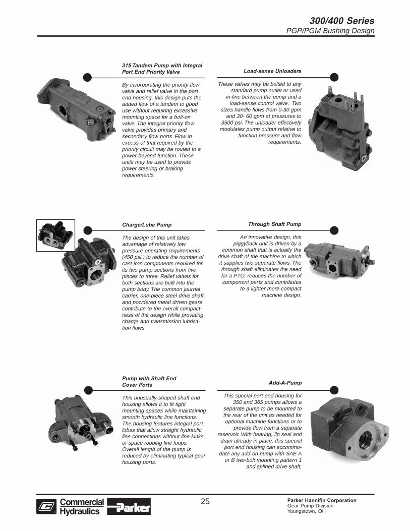
315 Tandem Pump with IntegralPort End Priority Valve
By incorporating the priority flowvalve and relief valve in the portend housing, this design puts theadded flow of a tandem to gooduse without requiring excessivemounting space for a bolt-onvalve. The integral priority flowvalve provides primary andsecondary flow ports. Flow inexcess of that required by thepriority circuit may be routed to apower beyond function. Theseunits may be used to providepower steering or brakingrequirements.
Pump with Shaft EndCover Ports
This unusually-shaped shaft endhousing allows it to fit tightmounting spaces while maintainingsmooth hydraulic line functions.The housing features integral portlobes that allow straight hydraulicline connections without line kinksor space robbing line loops.Overall length of the pump isreduced by eliminating typical gearhousing ports.
Load-sense Unloaders
These valves may be bolted to anystandard pump outlet or used
in-line between the pump and aload-sense control valve. Two
sizes handle flows from 0-30 gpmand 30- 60 gpm at pressures to
3500 psi. The unloader effectivelymodulates pump output relative to
function pressure and flowrequirements.
Through Shaft Pump
An innovative design, thispiggyback unit is driven by a
common shaft that is actually thedrive shaft of the machine to whichit supplies two separate flows. Thethrough shaft eliminates the needfor a PTO, reduces the number ofcomponent parts and contributes
to a lighter more compactmachine design.
Add-A-Pump
This special port end housing for350 and 365 pumps allows a
separate pump to be mounted tothe rear of the unit as needed foroptional machine functions or to
provide flow from a separatereservoir. With bearing, lip seal anddrain already in place, this special
port end housing can accommo-date any add-on pump with SAE A
or B two-bolt mounting pattern 1and splined drive shaft.
Charge/Lube Pump
The design of this unit takesadvantage of relatively lowpressure operating requirements(450 psi.) to reduce the number ofcast iron components required forits two pump sections from fivepieces to three. Relief valves forboth sections are built into thepump body. The common journalcarrier, one-piece steel drive shaft,and powdered metal driven gearscontribute to the overall compact-ness of the design while providingcharge and transmission lubrica-tion flows.
300/400 SeriesPGP/PGM Bushing Design
26 Parker Hannifin CorporationGear Pump DivisionYoungstown, OH
The items described in this document and other documents or descriptions provided by The Company, its subsidiaries and its authorized distributorsare hereby offered for sale at prices to be established by The Company, its subsidiaries and its authorized distributors. This offer and its acceptance byany customer ("Buyer") shall be governed by all of the following Terms and Conditions. Buyer’s order for any such items, when communicated to TheCompany, its subsidiary or an authorized distributor ("Seller") verbally or in writing, shall constitute acceptance of this offer.
paid by Buyer. Unless otherwise agreed, Seller shall have the right to alter,discard or otherwise dispose of any special tooling or other property in itssole discretion at any time.8. Buyer’s Property: Any designs, tools, patterns, materials, drawings,confidential information or equipment furnished by Buyer or any otheritems which become Buyer’s property, may be considered obsolete andmay be destroyed by Seller after two (2) consecutive years have elapsedwithout Buyer placing an order for the items which are manufactured usingsuch property, Seller shall not be responsible for any loss or damage tosuch property while it is in Seller’s possession or control.9. Taxes: Unless otherwise indicated on the face hereof, all prices andcharges are exclusive of excise, sales, use, property, occupational or liketaxes which may be imposed by any taxing authority upon the manufac-ture, sale or delivery of the items sold hereunder. If any such taxes mustbe paid by Seller or if Seller is liable for the collection of such tax, theamount thereof shall be in addition to the amounts for the items sold. Buyeragrees to pay all such taxes or to reimburse Seller therefore upon receiptof its invoice. If Buyer claims exemption from any sales, use or other taximposed by any taxing authority, Buyer shall save Seller harmless fromand against any such tax, together with any interest or penalties thereonwhich may be assessed if the items are held to be taxable.10. Indemnity For Infringement of Intellectual Property Rights: Sellershall have no liability for infringement of any patents, trademarks, copy-rights, trade dress, trade secrets or similar rights except as provided in thisPart 10. Seller will defend and indemnify Buyer against allegations ofinfringement of U.S. Patents, U.S. Trademarks, copyrights, trade dressand trade secrets (hereinafter ‘Intellectual Property Rights’). Seller willdefend at its expense and will pay the cost of any settlement or damagesawarded in an action brought against Buyer based on an allegation that anitem sold pursuant to this contract infringes the Intellectual Property Rightsof a third party. Seller’s obligation to defend and indemnify Buyer iscontingent on Buyer notifying Seller within ten (10) days after Buyerbecomes aware of such allegations of infringement, and Seller having solecontrol over the defense of any allegations or actions including allnegotiations for settlement or compromise. If an item sold hereunder issubject to a claim that it infringes the Intellectual Property Rights of a thirdparty, Seller may, at its sole expense and option, procure for Buyer the rightto continue using said item, replace or modify said item so as to make itnoninfringing, or offer to accept return of said item and return the purchaseprice less a reasonable allowance for depreciation. Notwithstanding theforegoing, Seller shall have no liability for claims of infringement based oninformation provided by Buyer, or directed to items delivered hereunder forwhich the designs are specified in whole or part by Buyer, or infringementsresulting from the modification, combination or use in a system of any itemsold hereunder. The foregoing provisions of this Part 10 shall constituteSeller’s sole and exclusive liability and Buyer’s sole and exclusive remedyfor infringement of Intellectual Property Rights.If a claim is based on information provided by Buyer or if the design for anitem delivered hereunder is specified in whole or in part by Buyer, Buyershall defend and indemnify Seller for all costs, expenses or judgmentsresulting from any claim that such item infringes any patent, trademark,copyright, trade dress, trade secret or any similar right.11. Force Majeure: Seller does not assume the risk of and shall not beliable for delay or failure to perform any of Seller’s obligations by reasonof circumstances beyond the reasonable control of Seller (hereinafter‘Events of Force Majeure’). Events of Force Majeure shall include withoutlimitation, accidents, acts of God, strikes or labor disputes, acts, laws, rulesor regulations of any government or government agency, fires, floods,delays or failures in delivery of carriers or suppliers, shortages of materialsand any other cause beyond Seller’s control.12. Entire Agreement/Governing Law: The terms and conditions setforth herein, together with any amendments, modifications and anydifferent terms or conditions expressly accepted by Seller in writing, shallconstitute the entire Agreement concerning the items sold, and there areno oral or other representations or agreements which pertain thereto. ThisAgreement shall be governed in all respects by the law of the State of Ohio.No actions arising out of the sale of the items sold hereunder or thisAgreement may be brought by either party more than two (2) years afterthe cause of action accrues.
9/91-P
1. Terms and Conditions of Sale: All descriptions, quotations, propos-als, offers, acknowledgments, acceptances and sales of Seller’s productsare subject to and shall be governed exclusively by the terms andconditions stated herein. Buyer’s acceptance of any offer to sell is limitedto these terms and conditions. Any terms or conditions in addition to, orinconsistent with those stated herein, proposed by Buyer in any accep-tance of an offer by Seller, are hereby objected to. No such additional,different or inconsistent terms and conditions shall become part of thecontract between Buyer and Seller unless expressly accepted in writingby Seller. Seller’s acceptance of any offer to purchase by Buyer isexpressly conditional upon Buyer’s assent to all the terms and conditionsstated herein, including any terms in addition to, or inconsistent with thosecontained in Buyer’s offer, Acceptance of Seller’s products shall in allevents constitute such assent.2. Payment: Payment shall be made by Buyer net 30 days from the dateof delivery of the items purchased hereunder. Amounts not timely paidshall bear interest at the maximum rate permitted by law for each monthor portion thereof that the Buyer is late in making payment. Any claims byBuyer for omissions or shortages in a shipment shall be waived unlessSeller receives notice thereof within 30 days after Buyer’s receipt of theshipment.3. Delivery: Unless otherwise provided on the face hereof, delivery shallbe made F.O.B. Seller’s plant. Regardless of the method of delivery,however, risk of loss shall pass to Buyer upon Seller’s delivery to a carrier.Any delivery dates shown are approximate only and Seller shall have noliability for any delays in delivery.4. Warranty: Seller warrants that the items sold hereunder shall be freefrom defects in material or workmanship for a period of 18 months fromdate of shipment from The Company. THIS WARRANTY COMPRISESTHE SOLE AND ENTIRE WARRANTY PERTAINING TO ITEMS PRO-VIDED HEREUNDER. SELLER MAKES NO OTHER WARRANTY,GUARANTEE, OR REPRESENTATION OF ANY KIND WHATSOEVER.ALL OTHER WARRANTIES, INCLUDING BUT NOT LIMITED TO,MERCHANTABILITY AND FITNESS FOR PURPOSE, WHETHER EX-PRESS, IMPLIED, OR ARISING BY OPERATION OF LAW, TRADEUSAGE, OR COURSE OF DEALING ARE HEREBY DISCLAIMED.NOTWITHSTANDING THE FOREGOING, THERE ARE NO WAR-RANTIES WHATSOEVER ON ITEMS BUILT OR ACQUIRED WHOLLYOR PARTIALLY, TO BUYER’S DESIGNS OR SPECIFICATIONS.5. Limitation Of Remedy: SELLER’S LIABILITY ARISING FROM OR INANY WAY CONNECTED WITH THE ITEMS SOLD OR THIS CON-TRACT SHALL BE LIMITED EXCLUSIVELY TO REPAIR OR RE-PLACEMENT OF THE ITEMS SOLD OR REFUND OF THE PURCHASEPRICE PAID BY BUYER, AT SELLER’S SOLE OPTION. IN NO EVENTSHALL SELLER BE LIABLE FOR ANY INCIDENTAL, CONSEQUEN-TIAL OR SPECIAL DAMAGES OF ANY KIND OR NATURE WHATSO-EVER, INCLUDING BUT NOT LIMITED TO LOST PROFITS ARISINGFROM OR IN ANY WAY CONNECTED WITH THIS AGREEMENT ORITEMS SOLD HEREUNDER, WHETHER ALLEGED TO ARISE FROMBREACH OF CONTRACT, EXPRESS OR IMPLIED WARRANTY, OR INTORT, INCLUDING WITHOUT LIMITATION, NEGLIGENCE, FAILURETO WARN OR STRICT LIABILITY.6. Changes, Reschedules and Cancellations: Buyer may request tomodify the designs or specifications for the items sold hereunder as wellas the quantities and delivery dates thereof, or may request to cancel allor part of this order, however, no such requested modification or cancel-lation shall become part of the contract between Buyer and Seller unlessaccepted by Seller in a written amendment to this Agreement. Acceptanceof any such requested modification or cancellation shall be at Seller’sdiscretion, and shall be upon such terms and conditions as Seller mayrequire.7. Special Tooling: A tooling charge may be imposed for any specialtooling, including without limitation, dies, fixtures, molds and patterns,acquired to manufacture items sold pursuant to this contract. Such specialtooling shall be and remain Seller’s property notwithstanding payment ofany charges by Buyer. In no event will Buyer acquire any interest inapparatus belonging to Seller which is utilized in the manufacture of theitems sold hereunder, even if such apparatus has been specially con-verted or adapted for such manufacture and notwithstanding any charges
Offer of Sale

300/400 SeriesPGP/PGM Bushing Design
27 Parker Hannifin CorporationGear Pump DivisionYoungstown, OH
The Aerospace Groupis a leader in the development,design, manufacture andservicing of control systemsand components for aerospaceand related high-technologymarkets, while achievinggrowth through premiercustomer service.
The Fluid ConnectorsGroup designs, manufacturesand markets rigid and flexibleconnectors, and associatedproducts used in pneumaticand fluid systems.
The Hydraulics Groupdesigns, produces andmarkets a full spectrumof hydraulic compnentsand systems to buildersand users of industrialand mobile machineryand equipment.
The Automation Groupis a leading supplier ofpneu-matic and electro-mechanical componentsand systems to automationcustomers worldwide.
The Climate & IndustrialControls Groupdesigns, manufactures andmarkets system-control andfluid-handling componentsand systems to refrigeration,air-conditioning and industrialcustomers worldwide.
The Seal Group designs,manufactures and distributesindustrial and commercialsealing devices and relatedproducts by providingsuperior quality andtotal customer satisfaction.
The Filtration Groupdesigns, manufactures andmarkets quality filtrationand clarification products,providing customers withthe best value, quality,technical support, andglobal availability.
The InstrumentationGroup is a global leaderin the design, manufactureand distribution of high-quality critical flowcomponents for worldwideprocessinstrumentation,ultra-high-purity, medicaland analytical applications.
Parker’s CharterTo be a leading worldwide manufacturer of componentsand systems for the builders and users of durablegoods. More specifically, we will design, market andmanufacture products controlling motion, flow andpressure. We will achieve profitable growth throughpremier customer service.
Product InformationNorth American customers seeking product information,the location of a nearby distributor, or repair serviceswill receive prompt attention by calling the ParkerProduct Information Center at our toll-free number:1-800-C-PARKER (1-800-272-7537). In the UK, a similarservice is available by calling 0500-103-203.
About Parker Hannifin CorporationParker Hannifin is a leading global motion-controlcompany dedicated to delivering premier customerservice. A Fortune 500 corporation listed on theNew York Stock Exchange (PH), our componentsand systems comprise over 1,400 product lines thatcontrol motion in some 1,000 industrial and aerospacemarkets. Parker is the only manufacturer to offer itscustomers a choice of hydraulic, pneumatic, andelectromechanical motion-control solutions. OurCompany has the largest distribution network in itsfield, with over 7,500 distributors serving more than350,000 customers worldwide.
Parker Hannifin Corporation6035 Parkland Blvd.Cleveland, Ohio 44124-4141Telephone: (216) 896-3000Fax: (216) 896-4000Web site: www.parker.com
Parker Hannifin Corporation
Parker Hannifin CorporationGear Pump Division1775 Logan AvenueYoungstown, OH 44501 USATel: (330) 746-8011Fax: (330) 746-1148www.parker.com
Catalog HY09-0300/US02/01 T&M 5M