Embed Size (px)
Citation preview
150
WWW.PRECIDIP.COm TEL +41 32 421 04 00 [email protected]
due to technical progress, all information provided is subject to change without prior notice.
SPECIFIC APPLICATIONSSOCKETSSOLDER TAIL / STAGGERED DIL AND SIL SOCKETS
TECHNICAL SPECIFICATIONS (FOR GENERAL SPECS, SEE PAGE 127)
INSULATOR Black glass filled polyester pct-Gf30-frFLAmmABILIT Y ul 94V-oSLEEvE Brass cuZn36pb3 (c36000)CONTACT CLIP (4 FINGER) Beryllium copper (c17200)ACCEPTED PIN Ø 0.40 to 0.56 mmFORCES 2 n typ. insertion 1 n typ. withdrawal (polished steel gauge Ø 0.43 mm)mECHANICAL LIFE Min. 100 cyclesRATED CURRENT 1 aCONTACT RESISTANCE Max. 10 mΩDIELECTRIC STRENGTH Min. 1’000 Vrms
ORDERING INFORmATION ROHS COmPLIANT PARTSPP PLATING CODE SLEEvE CLIP
87 tin flash gold83 tin 0.75 µm gold
Quad-in-line sockets and staggered (zig-zag) strips are suitable for ic's with staggered double row dual-in-line type pin patterns.
other plating on request (see page 178 for plating specs).
STAGGERED zIG-zAG STRIPS
NO. OF POLES A C vERSION SEE ORDER CODES
left fig. 2 410-PP-214-10-00110114* 19.00 5.0
right fig. 3 410-PP-214-10-002101 left fig. 2 410-PP-216-10-00110116 21.50 5.0
right fig. 3 410-PP-216-10-002101 left fig. 2 410-PP-220-10-00110120 26.57 5.0
right fig. 3 410-PP-220-10-002101 left fig. 2 410-PP-224-10-00110124 31.65 5.0
right fig. 3 410-PP-224-10-002101 left fig. 2 410-PP-228-10-00110128 36.73 5.0
right fig. 3 410-PP-228-10-002101 left fig. 2 410-PP-230-10-00110130 39.27 5.0
right fig. 3 410-PP-230-10-002101 left fig. 2 410-PP-240-10-00110140 52.00 5.0
right fig. 3 410-PP-240-10-002101
fig. 1
Fig. 2
fig. 3
* 14-pin strips are not stackable end to end
QUAD-IN-LINE SOCKET
NO. OF POLES SEE ORDER CODES
64 fig. 1 110-PP-064-01-505101
Note:suitable for quad-in-line packages with 19.05 / 23.50 mm rowspacing acc. to Jedec Mo-030.Quad-in-line socket layout requires 19.05 / 24.13 mm row spacing.
P128P151.indd 150 23.08.12 10:14
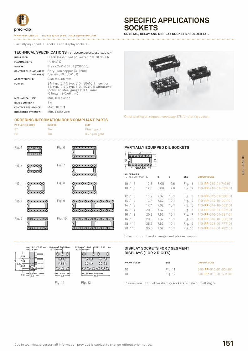
PARTIALLY EQUIPPED DIL SOCKETS
NO. OF POLEStotal eQuipped A B C SEE ORDER CODES
10 / 6 12.6 5.08 7.6 fig. 1 110-PP-210-01-74210110 / 8 12.6 5.08 7.6 fig. 2 110-PP-210-01-839101
12 / 6 15.2 7.62 10.1 fig. 3 110-PP-312-01-68010114 / 4 17.7 7.62 10.1 fig. 4 110-PP-314-10-00110114 / 8 17.7 7.62 10.1 fig. 5 110-PP-314-10-00210116 / 4 20.3 7.62 10.1 fig. 6 110-PP-316-01-82210116 / 8 20.3 7.62 10.1 fig. 7 110-PP-316-01-93110116 / 8 20.3 7.62 10.1 fig. 8 110-PP-316-10-00310128 / 14 35.5 7.62 10.1 fig. 9 110-PP-328-01-77710128 / 16 35.5 7.62 10.1 fig. 10 110-PP-328-01-762101
other pin count and arrangement please consult
WWW.PRECIDIP.COm TEL +41 32 421 04 00 [email protected]
SPECIFIC APPLICATIONSSOCKETSCRYSTAL, RELAY AND DISPLAY SOCKETS / SOLDER TAIL
151
TECHNICAL SPECIFICATIONS (FOR GENERAL SPECS, SEE PAGE 127)
INSULATOR Black glass filled polyester pct-Gf30-frFLAmmABILIT Y ul 94V-oSLEEvE Brass cuZn36pb3 (c36000)CONTACT CLIP (4 FINGER) Beryllium copper (c17200)CONTACT CLIP (6 FINGER) (series 510...504101)ACCEPTED PIN Ø 0.40 to 0.56 mmFORCES 2 n typ. (0.7 n typ. 510...504101) insertion 1 n typ. (0.4 n typ. 510...504101) withdrawal (polished steel gauge Ø 0.43 mm) (6 finger: Ø 0.46 mm)mECHANICAL LIFE Min. 100 cyclesRATED CURRENT 1 aCONTACT RESISTANCE Max. 10 mΩDIELECTRIC STRENGTH Min. 1’000 Vrms
ORDERING INFORmATION ROHS COmPLIANT PARTSPP PLATING CODE SLEEvE CLIP
87 tin flash gold83 tin 0.75 µm gold
partially equipped dil sockets and display sockets.
other plating on request (see page 178 for plating specs).
due to technical progress, all information provided is subject to change without prior notice.
DIL
SO
CK
ETS
fig. 1
fig. 2
fig. 3
fig. 4
fig. 5
fig. 6
fig. 7
fig. 8
fig. 9
fig. 10
fig. 11 fig. 12
DISPLAY SOCKETS FOR 7 SEGmENTDISPLAYS (1 OR 2 DIGITS)
NO. OF POLES SEE ORDER CODES
10 fig. 11 510-PP-010-01-50410118 fig. 12 510-PP-018-01-504101
please consult for other display sockets, single or multidigits
P128P151.indd 151 23.08.12 10:14
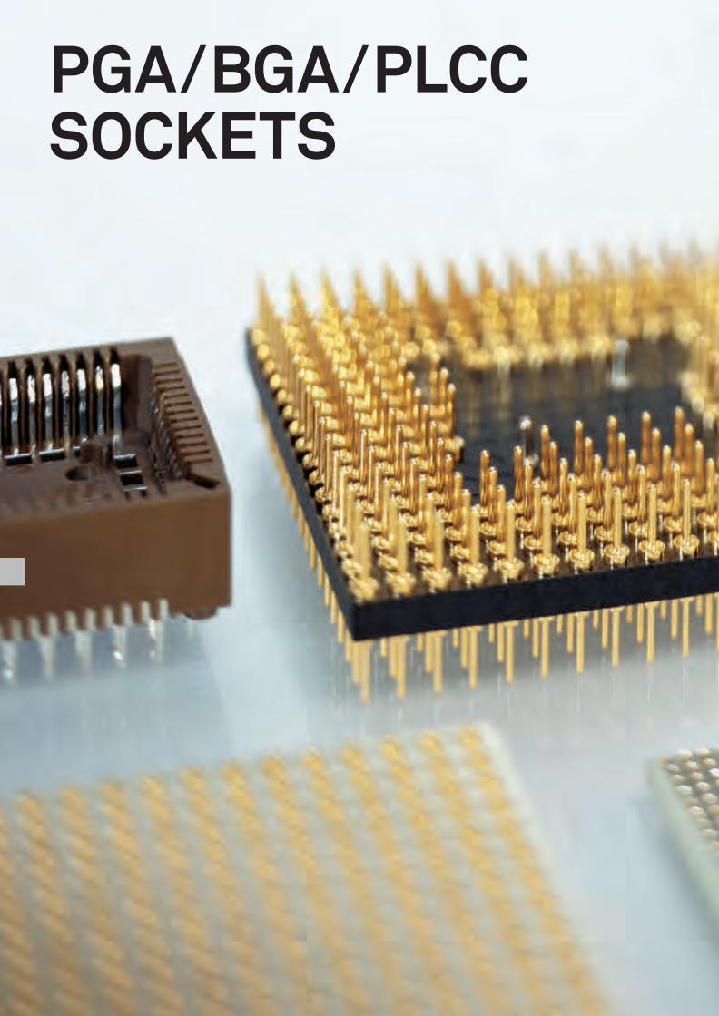
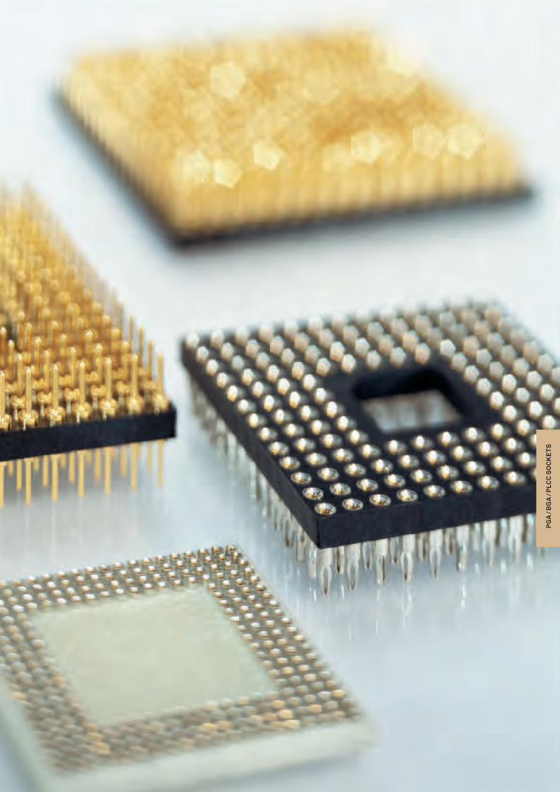
PGA / BGA / PLCC SOCKETS
PG
A /
BG
A /
PLC
C S
OC
KE
TS
154
WWW.PRECIDIP.COm TEL +41 32 421 04 00 [email protected]
due to technical progress, all information provided is subject to change without prior notice.
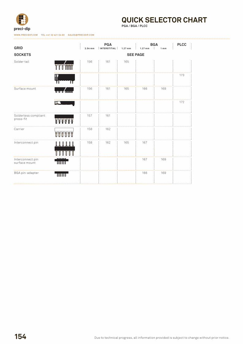
QUICK SELECTOR CHARTPGA / BGA / PLCC
PGA BGA PLCCGRID 2.54 mm INTERSTITIAL 1.27 mm 1.27 mm 1 mm
SOCKETS SEE PAGE
solder tail 156 161 165
173
surface mount 156 161 165 166 169
172
solderless compliant 157 161press-fit
carrier 158 162
interconnect pin 158 162 165 167
interconnect pin 167 169surface mount
BGa pin-adapter 166 169
P154P155.indd 154 23.08.12 10:14
WWW.PRECIDIP.COm TEL +41 32 421 04 00 [email protected]
PGA / BGA / PLCCGENERAL SPECIFICATIONS
155due to technical progress, all information provided is subject to change without prior notice.
the values listed below are general specs applying for preci-dip pGa, BGa and plcc sockets. please see individual catalog page for additional and product specific technical data.
OPERATING TEmPERATURE RANGE -55 ... +125 °cCLImATIC CATEGORY (IEC) 55/125/21OPERATING HUmIDIT Y RANGE annual mean 75% mA X. WORKING vOLTAGE 100 Vrms/150 Vdc (2.54 mm grid)
preci-dip connectors designated « series preci-dip connector » are recognized by ul llc and listed under « connectors for use in data, signal, control and power applications », file nr. e174442.
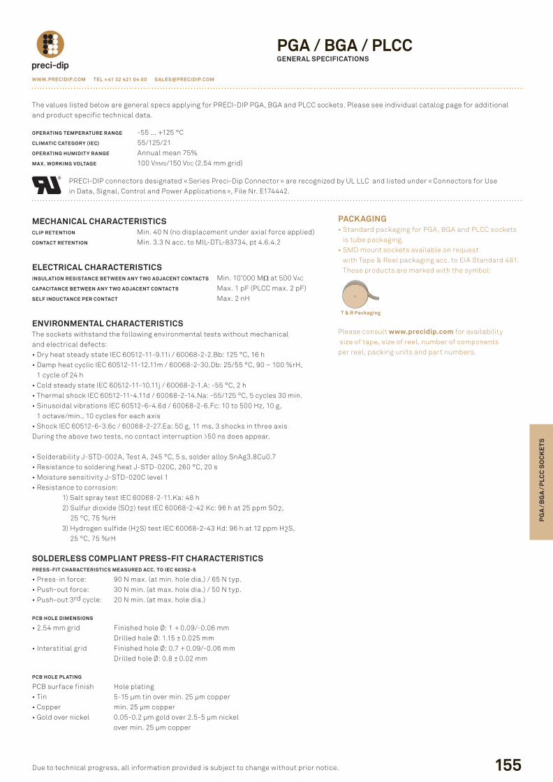
PACKAGING• standard packaging for pGa, BGa and plcc sockets
is tube packaging.• sMd mount sockets available on request
with tape & reel packaging acc. to eia standard 481. these products are marked with the symbol:
please consult www.precidip.com for availability size of tape, size of reel, number of components per reel, packing units and part numbers.
mECHANICAL CHARACTERISTICSCLIP RETENTION Min. 40 n (no displacement under axial force applied)CONTACT RETENTION Min. 3.3 n acc. to Mil-dtl-83734, pt 4.6.4.2
ELECTRICAL CHARACTERISTICSINSULATION RESISTANCE BETWEEN ANY TWO ADJACENT CONTACTS Min. 10’000 MΩ at 500 Vac
CAPACITANCE BETWEEN ANY TWO ADJACENT CONTACTS Max. 1 pf (plcc max. 2 pf)SELF INDUCTANCE PER CONTACT Max. 2 nh
ENvIRONmENTAL CHARACTERISTICS the sockets withstand the following environmental tests without mechanicaland electrical defects:• dry heat steady state iec 60512-11-9.11i / 60068-2-2.Bb: 125 °c, 16 h• damp heat cyclic iec 60512-11-12.11m / 60068-2-30.db: 25/55 °c, 90 – 100 %rh,
1 cycle of 24 h• cold steady state iec 60512-11-10.11j / 60068-2-1.a: -55 °c, 2 h• thermal shock iec 60512-11-4.11d / 60068-2-14.na: -55/125 °c, 5 cycles 30 min.• sinusoidal vibrations iec 60512-6-4.6d / 60068-2-6.fc: 10 to 500 hz, 10 g,
1 octave/min., 10 cycles for each axis• shock iec 60512-6-3.6c / 60068-2-27.ea: 50 g, 11 ms, 3 shocks in three axisduring the above two tests, no contact interruption >50 ns does appear.
• solderability J-std-002a, test a, 245 °c, 5 s, solder alloy snag3.8cu0.7• resistance to soldering heat J-std-020c, 260 °c, 20 s• Moisture sensitivity J-std-020c level 1• resistance to corrosion: 1) salt spray test iec 60068-2-11.ka: 48 h 2) sulfur dioxide (so2) test iec 60068-2-42 kc: 96 h at 25 ppm so2,
25 °c, 75 %rh 3) hydrogen sulfide (h2s) test iec 60068-2-43 kd: 96 h at 12 ppm h2s,
25 °c, 75 %rh
SOLDERLESS COmPLIANT PRESS-FIT CHARACTERISTICSPRESS-FIT CHARACTERISTICS mEASURED ACC. TO IEC 60352-5
• press-in force: 90 n max. (at min. hole dia.) / 65 n typ.• push-out force: 30 n min. (at max. hole dia.) / 50 n typ.• push-out 3rd cycle: 20 n min. (at max. hole dia.)
PCB HOLE DImENSIONS
• 2.54 mm grid finished hole Ø: 1 + 0.09/-0.06 mm drilled hole Ø: 1.15 ± 0.025 mm
• interstitial grid finished hole Ø: 0.7 + 0.09/-0.06 mm drilled hole Ø: 0.8 ± 0.02 mm
PCB HOLE PLATING
pcB surface finish hole plating• tin 5-15 µm tin over min. 25 µm copper• copper min. 25 µm copper• Gold over nickel 0.05-0.2 µm gold over 2.5-5 µm nickel
over min. 25 µm copper
T & R Packaging
PG
A /
BG
A /
PLC
C S
OC
KE
TS
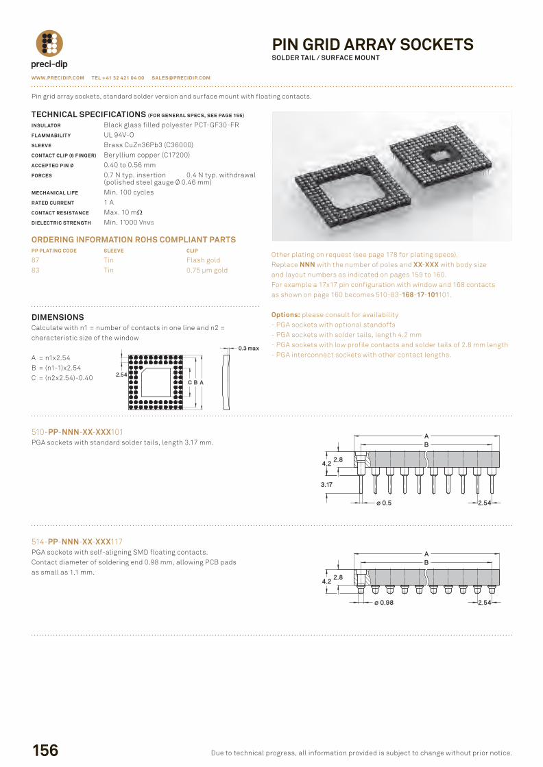
DImENSIONScalculate with n1 = number of contacts in one line and n2 =characteristic size of the window
a = n1x2.54B = (n1-1)x2.54c = (n2x2.54)-0.40
510-PP-NNN-XX-XXX101pGa sockets with standard solder tails, length 3.17 mm.
156
TECHNICAL SPECIFICATIONS (FOR GENERAL SPECS, SEE PAGE 155)
INSULATOR Black glass filled polyester pct-Gf30-frFLAmmABILIT Y ul 94V-oSLEEvE Brass cuZn36pb3 (c36000)CONTACT CLIP (6 FINGER) Beryllium copper (c17200)ACCEPTED PIN Ø 0.40 to 0.56 mmFORCES 0.7 n typ. insertion 0.4 n typ. withdrawal (polished steel gauge Ø 0.46 mm)mECHANICAL LIFE Min. 100 cyclesRATED CURRENT 1 aCONTACT RESISTANCE Max. 10 mΩDIELECTRIC STRENGTH Min. 1’000 Vrms
ORDERING INFORmATION ROHS COmPLIANT PARTSPP PLATING CODE SLEEvE CLIP
87 tin flash gold83 tin 0.75 µm gold
pin grid array sockets, standard solder version and surface mount with floating contacts.
other plating on request (see page 178 for plating specs).replace NNN with the number of poles and XX-XXX with body size and layout numbers as indicated on pages 159 to 160.for example a 17x17 pin configuration with window and 168 contacts as shown on page 160 becomes 510-83-168-17-101101.
Options: please consult for availability- pGa sockets with optional standoffs- pGa sockets with solder tails, length 4.2 mm- pGa sockets with low profile contacts and solder tails of 2.8 mm length- pGa interconnect sockets with other contact lengths.
WWW.PRECIDIP.COm TEL +41 32 421 04 00 [email protected]
due to technical progress, all information provided is subject to change without prior notice.
PIN GRID ARRAY SOCKETSSOLDER TAIL / SURFACE mOUNT
514-PP-NNN-XX-XXX117pGa sockets with self-aligning sMd floating contacts.contact diameter of soldering end 0.98 mm, allowing pcB pads as small as 1.1 mm.
P156P173.indd 156 23.08.12 10:15
WWW.PRECIDIP.COm TEL +41 32 421 04 00 [email protected]
157
PG
A /
BG
A /
PLC
C S
OC
KE
TS
due to technical progress, all information provided is subject to change without prior notice.
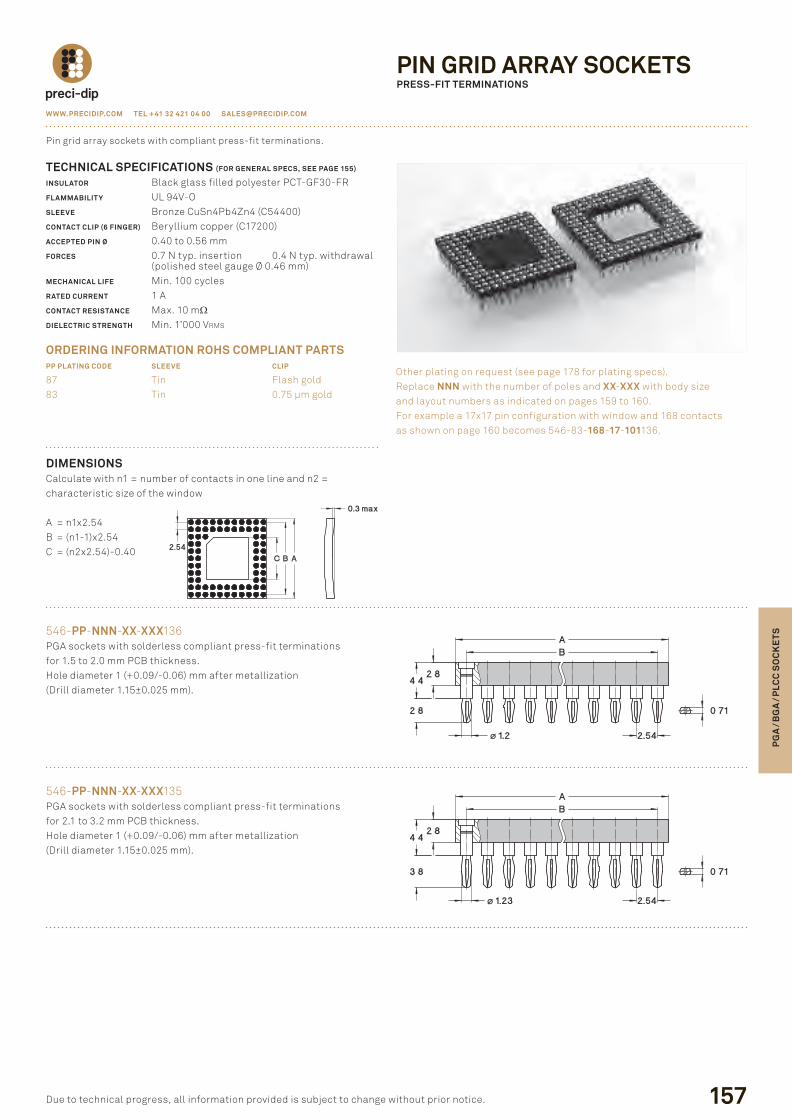
DImENSIONScalculate with n1 = number of contacts in one line and n2 =characteristic size of the window
a = n1x2.54B = (n1-1)x2.54c = (n2x2.54)-0.40
546-PP-NNN-XX-XXX136pGa sockets with solderless compliant press-fit terminationsfor 1.5 to 2.0 mm pcB thickness.hole diameter 1 (+0.09/-0.06) mm after metallization(drill diameter 1.15±0.025 mm).
TECHNICAL SPECIFICATIONS (FOR GENERAL SPECS, SEE PAGE 155)
INSULATOR Black glass filled polyester pct-Gf30-frFLAmmABILIT Y ul 94V-oSLEEvE Bronze cusn4pb4Zn4 (c54400)CONTACT CLIP (6 FINGER) Beryllium copper (c17200)ACCEPTED PIN Ø 0.40 to 0.56 mmFORCES 0.7 n typ. insertion 0.4 n typ. withdrawal (polished steel gauge Ø 0.46 mm)mECHANICAL LIFE Min. 100 cyclesRATED CURRENT 1 aCONTACT RESISTANCE Max. 10 mΩDIELECTRIC STRENGTH Min. 1’000 Vrms
ORDERING INFORmATION ROHS COmPLIANT PARTSPP PLATING CODE SLEEvE CLIP
87 tin flash gold83 tin 0.75 µm gold
pin grid array sockets with compliant press-fit terminations.
other plating on request (see page 178 for plating specs).replace NNN with the number of poles and XX-XXX with body size and layout numbers as indicated on pages 159 to 160.for example a 17x17 pin configuration with window and 168 contacts as shown on page 160 becomes 546-83-168-17-101136.
546-PP-NNN-XX-XXX135pGa sockets with solderless compliant press-fit terminationsfor 2.1 to 3.2 mm pcB thickness.hole diameter 1 (+0.09/-0.06) mm after metallization(drill diameter 1.15±0.025 mm).
PIN GRID ARRAY SOCKETSPRESS-FIT TERmINATIONS
P156P173.indd 157 23.08.12 10:15
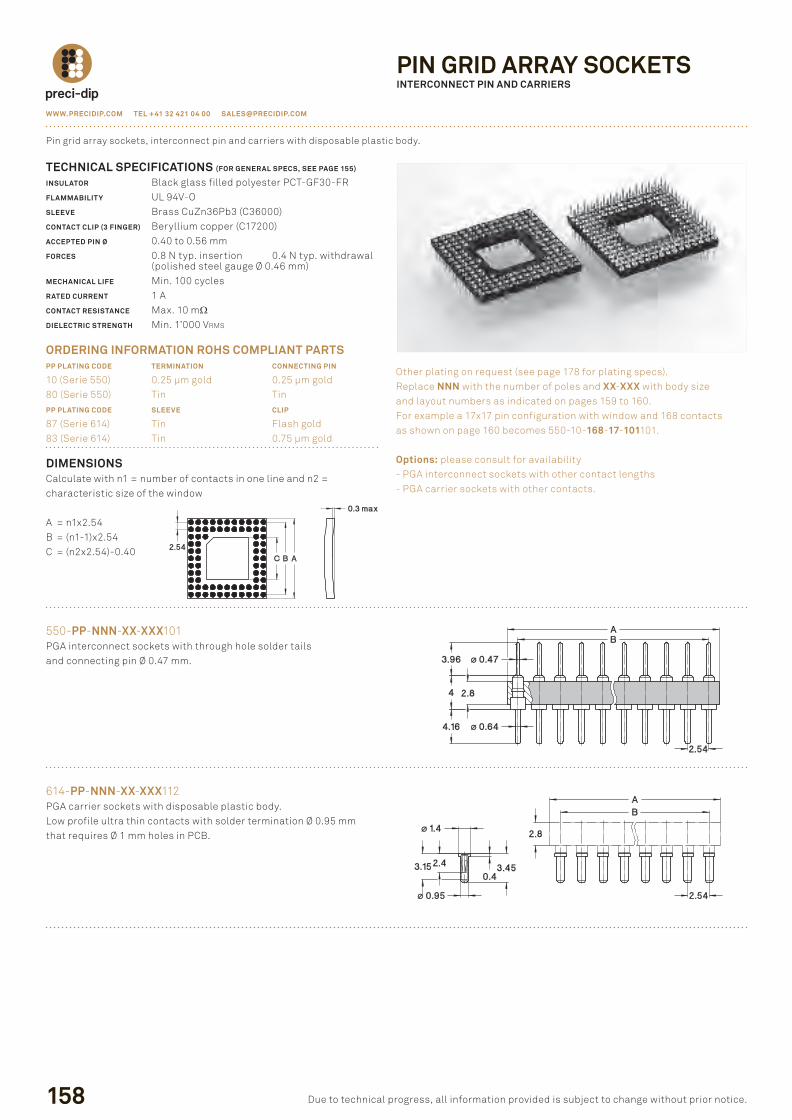
DImENSIONScalculate with n1 = number of contacts in one line and n2 =characteristic size of the window
a = n1x2.54B = (n1-1)x2.54c = (n2x2.54)-0.40
550-PP-NNN-XX-XXX101pGa interconnect sockets with through hole solder tails and connecting pin Ø 0.47 mm.
158
TECHNICAL SPECIFICATIONS (FOR GENERAL SPECS, SEE PAGE 155)
INSULATOR Black glass filled polyester pct-Gf30-frFLAmmABILIT Y ul 94V-oSLEEvE Brass cuZn36pb3 (c36000)CONTACT CLIP (3 FINGER) Beryllium copper (c17200)ACCEPTED PIN Ø 0.40 to 0.56 mmFORCES 0.8 n typ. insertion 0.4 n typ. withdrawal (polished steel gauge Ø 0.46 mm)mECHANICAL LIFE Min. 100 cyclesRATED CURRENT 1 aCONTACT RESISTANCE Max. 10 mΩDIELECTRIC STRENGTH Min. 1’000 Vrms
ORDERING INFORmATION ROHS COmPLIANT PARTSPP PLATING CODE TERmINATION CONNECTING PIN
10 (serie 550) 0.25 µm gold 0.25 µm gold80 (serie 550) tin tinPP PLATING CODE SLEEvE CLIP
87 (serie 614) tin flash gold83 (serie 614) tin 0.75 µm gold
pin grid array sockets, interconnect pin and carriers with disposable plastic body.
other plating on request (see page 178 for plating specs).replace NNN with the number of poles and XX-XXX with body size and layout numbers as indicated on pages 159 to 160.for example a 17x17 pin configuration with window and 168 contacts as shown on page 160 becomes 550-10-168-17-101101.
Options: please consult for availability- pGa interconnect sockets with other contact lengths- pGa carrier sockets with other contacts.
WWW.PRECIDIP.COm TEL +41 32 421 04 00 [email protected]
due to technical progress, all information provided is subject to change without prior notice.
PIN GRID ARRAY SOCKETSINTERCONNECT PIN AND CARRIERS
614-PP-NNN-XX-XXX112pGa carrier sockets with disposable plastic body.low profile ultra thin contacts with solder termination Ø 0.95 mm that requires Ø 1 mm holes in pcB.
P156P173.indd 158 23.08.12 10:15
WWW.PRECIDIP.COm TEL +41 32 421 04 00 [email protected]
159
PG
A /
BG
A /
PLC
C S
OC
KE
TS
due to technical progress, all information provided is subject to change without prior notice.
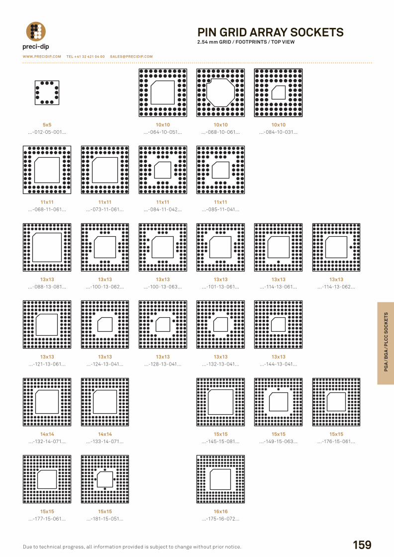
PIN GRID ARRAY SOCKETS2.54 mm GRID / FOOTPRINTS / TOP vIEW
5x5…-012-05-001…
10x10…-064-10-051…
10x10…-084-10-031…
11x11…-068-11-061…
11x11…-073-11-061…
11x11…-085-11-041…
13x13…-088-13-081…
13x13…-100-13-062…
13x13…-101-13-061…
13x13…-121-13-061…
13x13…-124-13-041…
13x13…-128-13-041…
13x13…-132-13-041…
13x13…-144-13-041…
14x14…-132-14-071…
14x14…-133-14-071…
15x15…-145-15-081…
15x15…-149-15-063…
15x15…-177-15-061…
15x15…-181-15-051…
16x16…-175-16-072…
10x10…-068-10-061…
11x11…-084-11-042…
13x13…-100-13-063…
13x13…-114-13-061…
13x13…-114-13-062…
15x15…-176-15-061…
P156P173.indd 159 23.08.12 10:15
160
WWW.PRECIDIP.COm TEL +41 32 421 04 00 [email protected]
due to technical progress, all information provided is subject to change without prior notice.
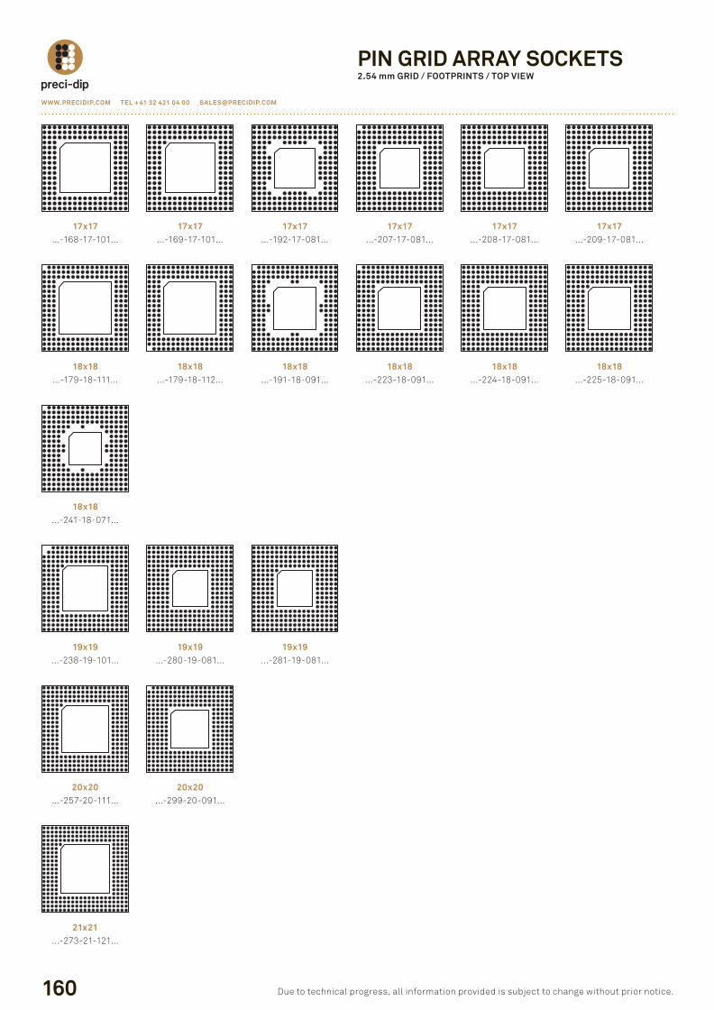
PIN GRID ARRAY SOCKETS2.54 mm GRID / FOOTPRINTS / TOP vIEW
17x17…-168-17-101…
17x17…-169-17-101…
17x17…-192-17-081…
17x17…-208-17-081…
17x17…-209-17-081…
18x18…-179-18-111…
18x18…-179-18-112…
18x18…-223-18-091…
18x18…-224-18-091…
18x18…-225-18-091…
18x18…-241-18-071…
19x19…-238-19-101…
19x19…-280-19-081…
19x19…-281-19-081…
20x20…-257-20-111…
20x20…-299-20-091…
21x21…-273-21-121…
17x17…-207-17-081…
18x18…-191-18-091…
P156P173.indd 160 23.08.12 10:15
WWW.PRECIDIP.COm TEL +41 32 421 04 00 [email protected]
161
PG
A /
BG
A /
PLC
C S
OC
KE
TS
due to technical progress, all information provided is subject to change without prior notice.
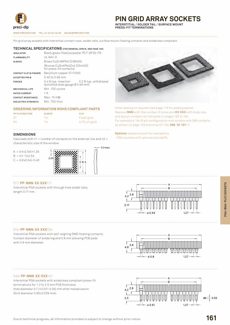
DImENSIONScalculate with n1 = number of contacts on the external row and n2 = characteristic size of the window
a = (n1x2.54)+1.30B = (n1-1)x2.54c = (n2x2.54)-0.40
517-PP-NNN-XX-XXX111interstitial pGa sockets with through hole solder tails, length 3.17 mm.
TECHNICAL SPECIFICATIONS (FOR GENERAL SPECS, SEE PAGE 155)
INSULATOR Black glass filled polyester pct-Gf30-frFLAmmABILIT Y ul 94V-oSLEEvE Brass cuZn36pb3 (c36000) (Bronze cusn4pb4Zn4 (c54400) for press-fit contacts)CONTACT CLIP (6 FINGER) Beryllium copper (c17200)ACCEPTED PIN Ø 0.40 to 0.56 mmFORCES 0.4 n typ. insertion 0.2 n typ. withdrawal (polished steel gauge Ø 0.46 mm)mECHANICAL LIFE Min. 100 cyclesRATED CURRENT 1 aCONTACT RESISTANCE Max. 10 mΩDIELECTRIC STRENGTH Min. 700 Vrms
ORDERING INFORmATION ROHS COmPLIANT PARTSPP PLATING CODE SLEEvE CLIP
87 tin flash gold83 tin 0.75 µm gold
pin grid array sockets with interstitial contact rows, solder tails, surface mount floating contacts and solderless compliant.
other plating on request (see page 178 for plating specs).replace NNN with the number of poles and XX-XXX with body size and layout numbers as indicated on pages 163 to 164. for example a 19x19 pin configuration with window and 296 contacts as shown on page 163 becomes 517-83-296-19-131111.
Options: please consult for availability- pGa sockets with optional standoffs.
514-PP-NNN-XX-XXX154interstitial pGa sockets with self-aligning sMd floating contacts.contact diameter of soldering end 0.8 mm allowing pcB pads with 0.9 mm diameter.
546-PP-NNN-XX-XXX147interstitial pGa sockets with solderless compliant press-fit terminations for 1.2 to 2.5 mm pcB thickness.hole diameter 0.7 (+0.07/-0.05) mm after metallization (drill diameter 0.85±0.025 mm).
PIN GRID ARRAY SOCKETSINTERSTITIAL / SOLDER TAIL / SURFACE mOUNTPRESS-FIT TERmINATIONS
P156P173.indd 161 23.08.12 10:15
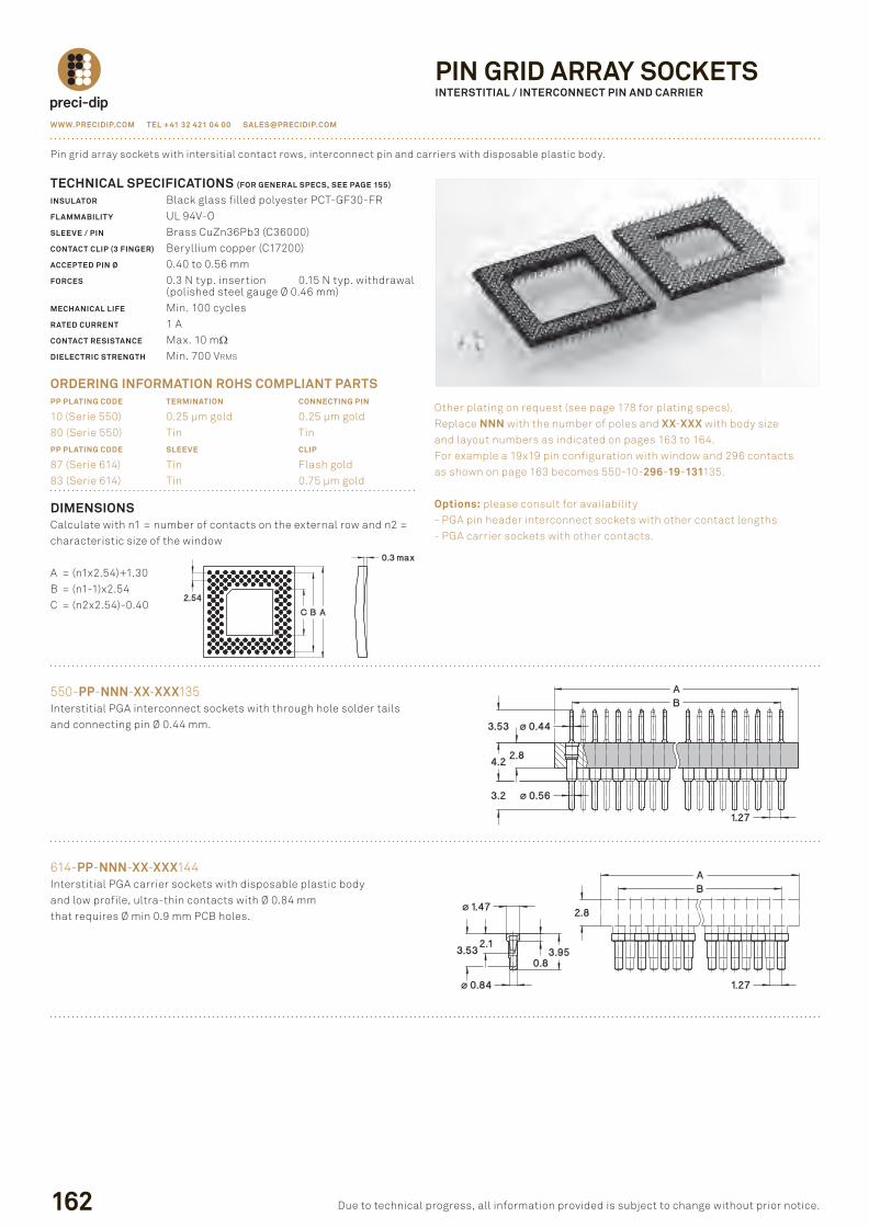
DImENSIONScalculate with n1 = number of contacts on the external row and n2 = characteristic size of the window
a = (n1x2.54)+1.30B = (n1-1)x2.54c = (n2x2.54)-0.40
550-PP-NNN-XX-XXX135interstitial pGa interconnect sockets with through hole solder tails and connecting pin Ø 0.44 mm.
162
TECHNICAL SPECIFICATIONS (FOR GENERAL SPECS, SEE PAGE 155)
INSULATOR Black glass filled polyester pct-Gf30-frFLAmmABILIT Y ul 94V-oSLEEvE / PIN Brass cuZn36pb3 (c36000)CONTACT CLIP (3 FINGER) Beryllium copper (c17200)ACCEPTED PIN Ø 0.40 to 0.56 mmFORCES 0.3 n typ. insertion 0.15 n typ. withdrawal (polished steel gauge Ø 0.46 mm)mECHANICAL LIFE Min. 100 cyclesRATED CURRENT 1 aCONTACT RESISTANCE Max. 10 mΩDIELECTRIC STRENGTH Min. 700 Vrms
ORDERING INFORmATION ROHS COmPLIANT PARTSPP PLATING CODE TERmINATION CONNECTING PIN
10 (serie 550) 0.25 µm gold 0.25 µm gold80 (serie 550) tin tinPP PLATING CODE SLEEvE CLIP
87 (serie 614) tin flash gold83 (serie 614) tin 0.75 µm gold
pin grid array sockets with intersitial contact rows, interconnect pin and carriers with disposable plastic body.
other plating on request (see page 178 for plating specs).replace NNN with the number of poles and XX-XXX with body size and layout numbers as indicated on pages 163 to 164. for example a 19x19 pin configuration with window and 296 contacts as shown on page 163 becomes 550-10-296-19-131135.
Options: please consult for availability- pGa pin header interconnect sockets with other contact lengths- pGa carrier sockets with other contacts.
WWW.PRECIDIP.COm TEL +41 32 421 04 00 [email protected]
due to technical progress, all information provided is subject to change without prior notice.
PIN GRID ARRAY SOCKETSINTERSTITIAL / INTERCONNECT PIN AND CARRIER
614-PP-NNN-XX-XXX144interstitial pGa carrier sockets with disposable plastic body and low profile, ultra-thin contacts with Ø 0.84 mm that requires Ø min 0.9 mm pcB holes.
P156P173.indd 162 23.08.12 10:15
WWW.PRECIDIP.COm TEL +41 32 421 04 00 [email protected]
163
PG
A /
BG
A /
PLC
C S
OC
KE
TS
due to technical progress, all information provided is subject to change without prior notice.
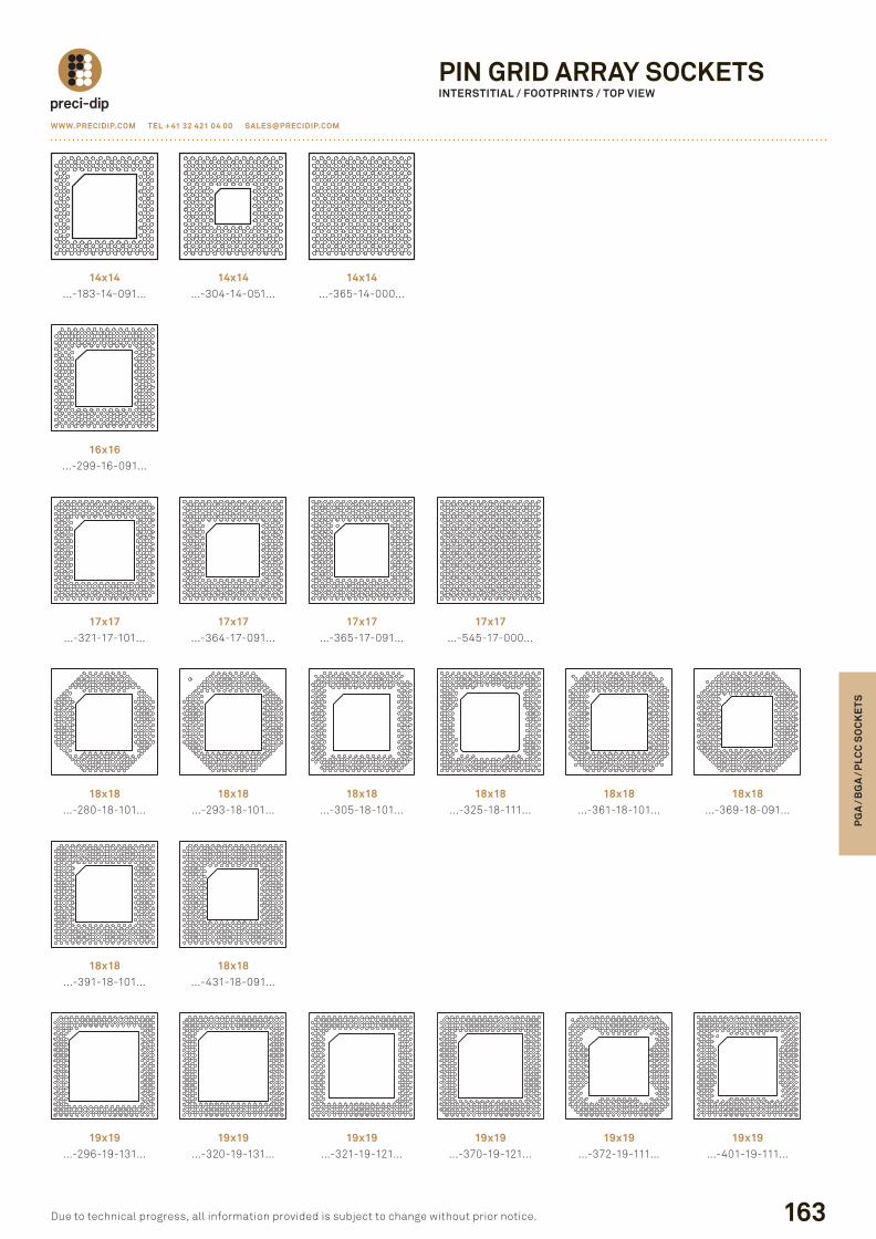
PIN GRID ARRAY SOCKETSINTERSTITIAL / FOOTPRINTS / TOP vIEW
14x14…-183-14-091…
14x14…-304-14-051…
14x14…-365-14-000…
16x16…-299-16-091…
17x17…-321-17-101…
17x17…-364-17-091…
17x17…-545-17-000…
18x18…-280-18-101…
18x18…-293-18-101…
18x18…-305-18-101…
18x18…-325-18-111…
18x18…-361-18-101…
18x18…-391-18-101…
18x18…-431-18-091…
19x19…-296-19-131…
19x19…-320-19-131…
19x19…-321-19-121…
19x19…-370-19-121…
19x19…-372-19-111…
19x19…-401-19-111…
17x17…-365-17-091…
18x18…-369-18-091…
P156P173.indd 163 23.08.12 10:15
164
WWW.PRECIDIP.COm TEL +41 32 421 04 00 [email protected]
due to technical progress, all information provided is subject to change without prior notice.
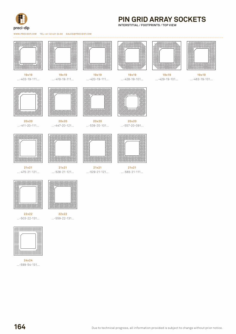
PIN GRID ARRAY SOCKETSINTERSTITIAL / FOOTPRINTS / TOP vIEW
19x19…-403-19-111…
19x19…-419-19-111…
19x19…-420-19-111…
19x19…-429-19-101…
19x19…-463-19-101…
20x20…-411-20-111…
20x20…-447-20-121…
20x20…-557-20-091…
21x21…-475-21-121…
21x21…-528-21-121…
21x21…-565-21-111…
22x22…-503-22-131…
22x22…-559-22-131…
24x24…-599-54-131…
19x19…-428-19-101…
20x20…-539-20-101…
21x21…-529-21-121…
P156P173.indd 164 23.08.12 10:15
WWW.PRECIDIP.COm TEL +41 32 421 04 00 [email protected]
165
PG
A /
BG
A /
PLC
C S
OC
KE
TS
due to technical progress, all information provided is subject to change without prior notice.
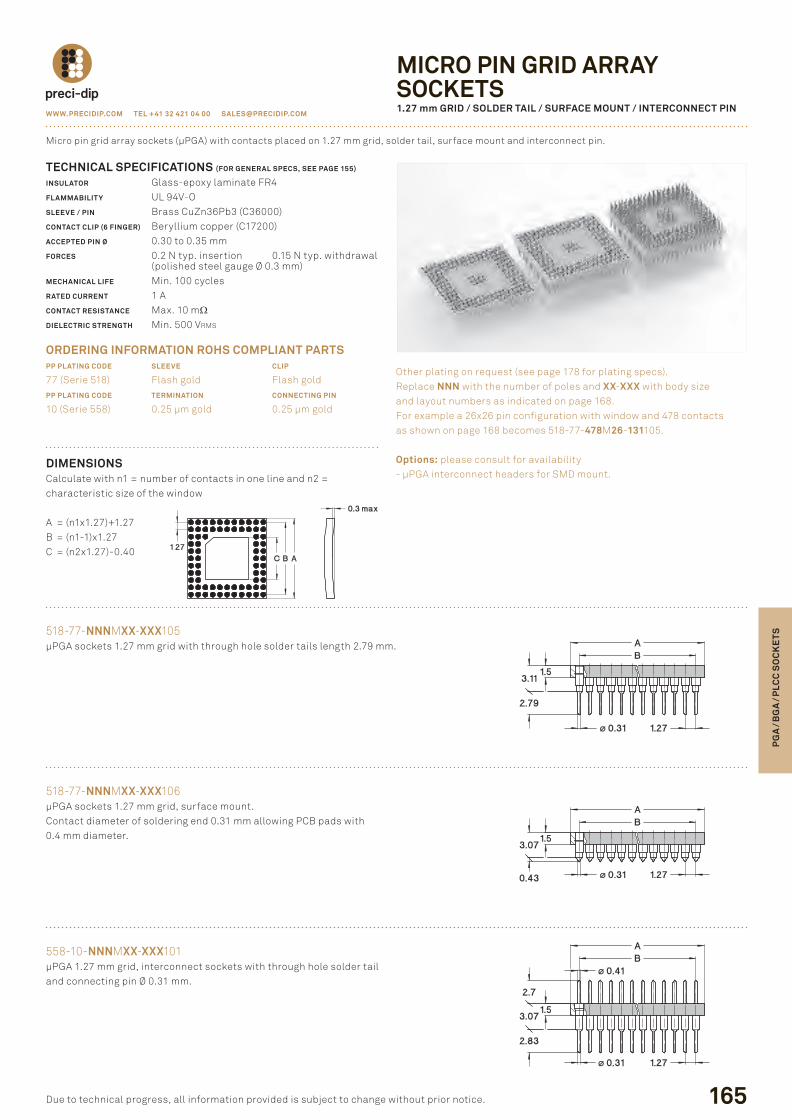
DImENSIONScalculate with n1 = number of contacts in one line and n2 =characteristic size of the window
a = (n1x1.27)+1.27B = (n1-1)x1.27c = (n2x1.27)-0.40
518-77-NNNMXX-XXX105µpGa sockets 1.27 mm grid with through hole solder tails length 2.79 mm.
TECHNICAL SPECIFICATIONS (FOR GENERAL SPECS, SEE PAGE 155)
INSULATOR Glass-epoxy laminate fr4FLAmmABILIT Y ul 94V-oSLEEvE / PIN Brass cuZn36pb3 (c36000)CONTACT CLIP (6 FINGER) Beryllium copper (c17200)ACCEPTED PIN Ø 0.30 to 0.35 mmFORCES 0.2 n typ. insertion 0.15 n typ. withdrawal (polished steel gauge Ø 0.3 mm)mECHANICAL LIFE Min. 100 cyclesRATED CURRENT 1 aCONTACT RESISTANCE Max. 10 mΩDIELECTRIC STRENGTH Min. 500 Vrms
ORDERING INFORmATION ROHS COmPLIANT PARTSPP PLATING CODE SLEEvE CLIP
77 (serie 518) flash gold flash goldPP PLATING CODE TERmINATION CONNECTING PIN
10 (serie 558) 0.25 µm gold 0.25 µm gold
Micro pin grid array sockets (µpGa) with contacts placed on 1.27 mm grid, solder tail, surface mount and interconnect pin.
other plating on request (see page 178 for plating specs).replace NNN with the number of poles and XX-XXX with body size and layout numbers as indicated on page 168. for example a 26x26 pin configuration with window and 478 contacts as shown on page 168 becomes 518-77-478M26-131105.
Options: please consult for availability- µpGa interconnect headers for sMd mount.
518-77-NNNMXX-XXX106µpGa sockets 1.27 mm grid, surface mount.contact diameter of soldering end 0.31 mm allowing pcB pads with0.4 mm diameter.
558-10-NNNMXX-XXX101µpGa 1.27 mm grid, interconnect sockets with through hole solder tail and connecting pin Ø 0.31 mm.
mICRO PIN GRID ARRAYSOCKETS1.27 mm GRID / SOLDER TAIL / SURFACE mOUNT / INTERCONNECT PIN
P156P173.indd 165 23.08.12 10:15
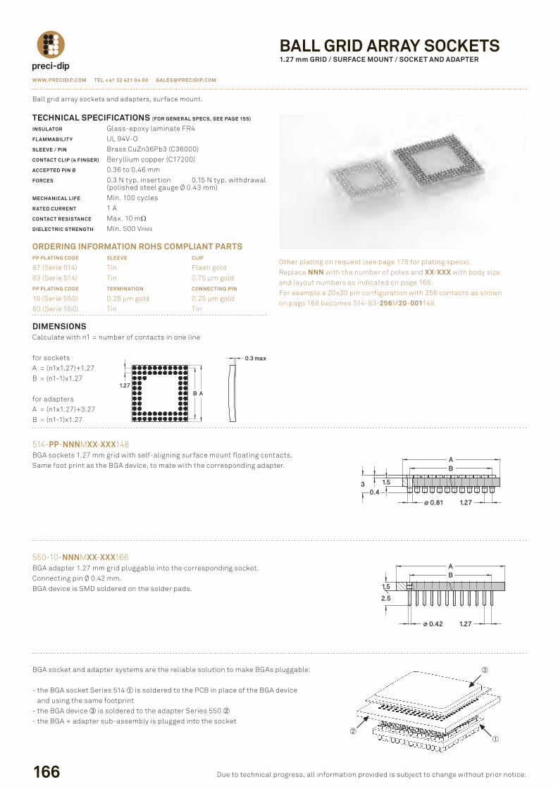
DImENSIONScalculate with n1 = number of contacts in one line
for socketsa = (n1x1.27)+1.27B = (n1-1)x1.27
for adaptersa = (n1x1.27)+3.27B = (n1-1)x1.27
514-PP-NNNMXX-XXX148BGa sockets 1.27 mm grid with self-aligning surface mount floating contacts.same foot print as the BGa device, to mate with the corresponding adapter.
166
TECHNICAL SPECIFICATIONS (FOR GENERAL SPECS, SEE PAGE 155)
INSULATOR Glass-epoxy laminate fr4FLAmmABILIT Y ul 94V-oSLEEvE / PIN Brass cuZn36pb3 (c36000)CONTACT CLIP (4 FINGER) Beryllium copper (c17200)ACCEPTED PIN Ø 0.36 to 0.46 mmFORCES 0.3 n typ. insertion 0.15 n typ. withdrawal (polished steel gauge Ø 0.43 mm)mECHANICAL LIFE Min. 100 cyclesRATED CURRENT 1 aCONTACT RESISTANCE Max. 10 mΩDIELECTRIC STRENGTH Min. 500 Vrms
ORDERING INFORmATION ROHS COmPLIANT PARTSPP PLATING CODE SLEEvE CLIP
87 (serie 514) tin flash gold83 (serie 514) tin 0.75 µm goldPP PLATING CODE TERmINATION CONNECTING PIN
10 (serie 550) 0.25 µm gold 0.25 µm gold80 (serie 550) tin tin
Ball grid array sockets and adapters, surface mount.
other plating on request (see page 178 for plating specs).replace NNN with the number of poles and XX-XXX with body size and layout numbers as indicated on page 168. for example a 20x20 pin configuration with 256 contacts as shown on page 168 becomes 514-83-256M20-001148.
WWW.PRECIDIP.COm TEL +41 32 421 04 00 [email protected]
due to technical progress, all information provided is subject to change without prior notice.
BALL GRID ARRAY SOCKETS1.27 mm GRID / SURFACE mOUNT / SOCKET AND ADAPTER
550-10-NNNMXX-XXX166BGa adapter 1.27 mm grid pluggable into the corresponding socket.connecting pin Ø 0.42 mm.BGa device is sMd soldered on the solder pads.
BGa socket and adapter systems are the reliable solution to make BGas pluggable:
- the BGa socket series 514 is soldered to the pcB in place of the BGa device and using the same footprint
- the BGa device is soldered to the adapter series 550 - the BGa + adapter sub-assembly is plugged into the socket
P156P173.indd 166 23.08.12 10:15
WWW.PRECIDIP.COm TEL +41 32 421 04 00 [email protected]
167
PG
A /
BG
A /
PLC
C S
OC
KE
TS
due to technical progress, all information provided is subject to change without prior notice.
DImENSIONScalculate with n1 = number of contacts in one line
a = (n1x1.27)+3.27B = (n1-1)x1.27
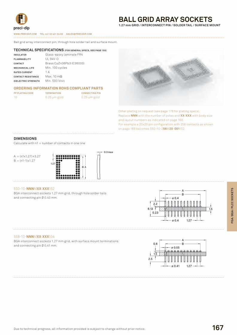
550-10-NNNMXX-XXX152BGa interconnect sockets 1.27 mm grid, through hole solder tails and connecting pin Ø 0.40 mm.
TECHNICAL SPECIFICATIONS (FOR GENERAL SPECS, SEE PAGE 155)
INSULATOR Glass-epoxy laminate fr4FLAmmABILIT Y ul 94V-oCONTACT Brass cuZn36pb3 (c36000)mECHANICAL LIFE Min. 100 cyclesRATED CURRENT 1 aCONTACT RESISTANCE Max. 10 mΩDIELECTRIC STRENGTH Min. 500 Vrms
ORDERING INFORmATION ROHS COmPLIANT PARTSPP PLATING CODE TERmINATION CONNECTING PIN
10 0.25 µm gold 0.25 µm gold
Ball grid array interconnect pin, through hole solder tail and surface mount.
other plating on request (see page 178 for plating specs).replace NNN with the number of poles and XX-XXX with body size and layout numbers as indicated on page 168. for example a 20x20 pin configuration with 256 contacts as shown on page 168 becomes 550-10-256M20-001152.
558-10-NNNMXX-XXX104BGa interconnect sockets 1.27 mm grid, with surface mount terminations and connecting pin Ø 0.41 mm.
BALL GRID ARRAY SOCKETS1.27 mm GRID / INTERCONNECT PIN / SOLDER TAIL / SURFACE mOUNT
P156P173.indd 167 23.08.12 10:15
168
WWW.PRECIDIP.COm TEL +41 32 421 04 00 [email protected]
due to technical progress, all information provided is subject to change without prior notice.
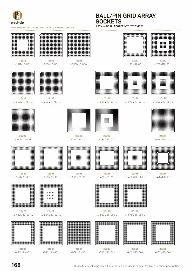
BALL/PIN GRID ARRAYSOCKETS1.27 mm GRID / FOOTPRINTS / TOP vIEW
16x16…-192M16-001…
16x16…-255M16-001…
16x16…-256M16-000…
17x17…-120M17-001…
17x17…-233M17-001…
19x19…-357M19-001…
19x19…-360M19-001…
20x20…-256M20-001…
20x20…-272M20-001…
20x20…-292M20-001…
20x20…-400M20-000…
23x23…-304M23-001…
26x26…-352M26-001…
26x26…-356M26-001…
26x26…-388M26-001…
26x26…-420M26-001…
26x26…-456M26-001…
29x29…-480M29-001…
29x29…-504M29-001…
30x30…-500M30-001…
30x30…-576M30-001…
31x31…-432M31-001…
31x31…-520M31-001…
31x31…-956M31-001…
33x33…-560M33-001…
35x35…-600M35-001…
35x35…-652M35-001…
26x26…-478M26-131…
23x23…-385M23-001…
24x24…-575M24-001…
P156P173.indd 168 23.08.12 10:15
WWW.PRECIDIP.COm TEL +41 32 421 04 00 [email protected]
169
PG
A /
BG
A /
PLC
C S
OC
KE
TS
due to technical progress, all information provided is subject to change without prior notice.
DImENSIONScalculate with n1 = number of contacts in one line
a = n1+2.81B = n1-1
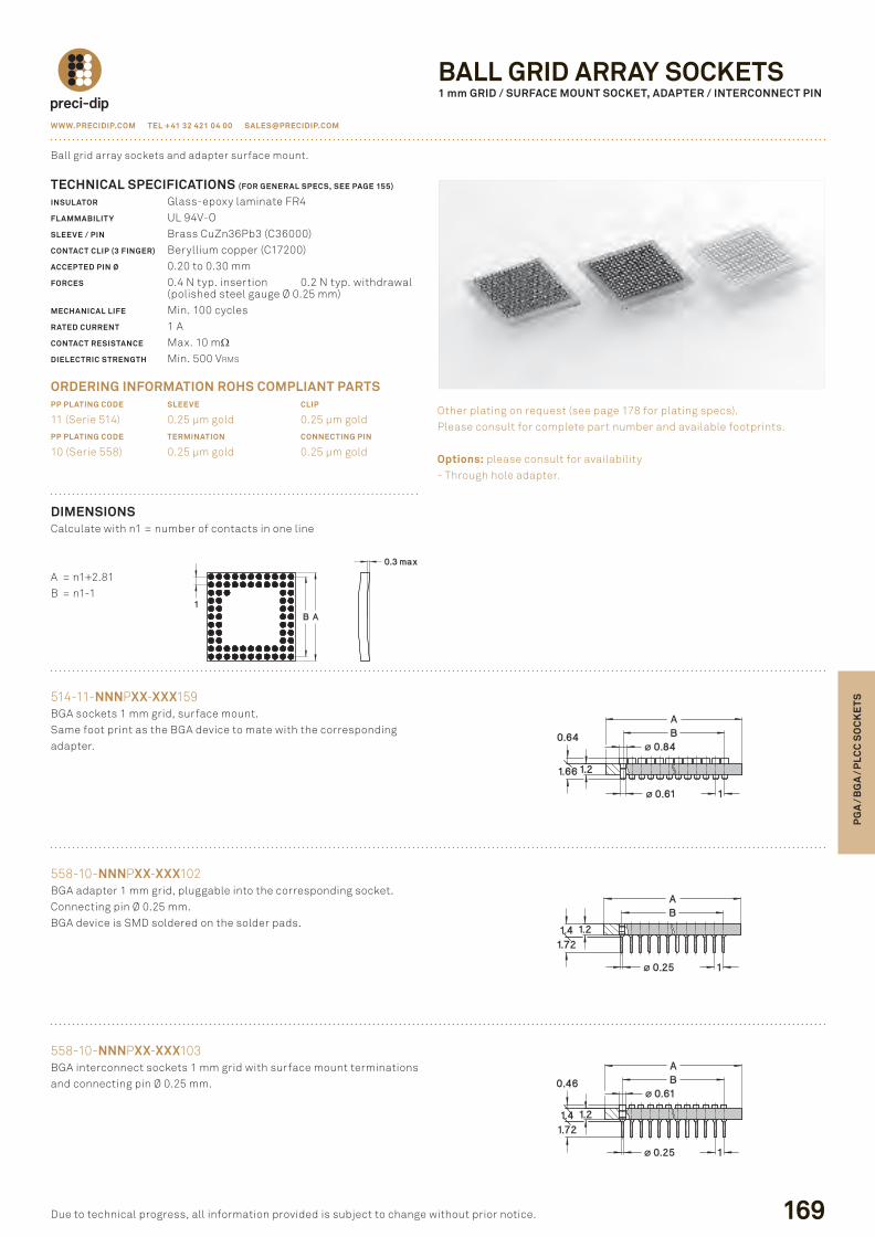
514-11-NNNpXX-XXX159BGa sockets 1 mm grid, surface mount.same foot print as the BGa device to mate with the correspondingadapter.
TECHNICAL SPECIFICATIONS (FOR GENERAL SPECS, SEE PAGE 155)
INSULATOR Glass-epoxy laminate fr4FLAmmABILIT Y ul 94V-oSLEEvE / PIN Brass cuZn36pb3 (c36000)CONTACT CLIP (3 FINGER) Beryllium copper (c17200)ACCEPTED PIN Ø 0.20 to 0.30 mmFORCES 0.4 n typ. insertion 0.2 n typ. withdrawal (polished steel gauge Ø 0.25 mm)mECHANICAL LIFE Min. 100 cyclesRATED CURRENT 1 aCONTACT RESISTANCE Max. 10 mΩDIELECTRIC STRENGTH Min. 500 Vrms
ORDERING INFORmATION ROHS COmPLIANT PARTSPP PLATING CODE SLEEvE CLIP
11 (serie 514) 0.25 µm gold 0.25 µm goldPP PLATING CODE TERmINATION CONNECTING PIN
10 (serie 558) 0.25 µm gold 0.25 µm gold
Ball grid array sockets and adapter surface mount.
other plating on request (see page 178 for plating specs).please consult for complete part number and available footprints.
Options: please consult for availability- through hole adapter.
558-10-NNNpXX-XXX102BGa adapter 1 mm grid, pluggable into the corresponding socket.connecting pin Ø 0.25 mm.BGa device is sMd soldered on the solder pads.
558-10-NNNpXX-XXX103BGa interconnect sockets 1 mm grid with surface mount terminations and connecting pin Ø 0.25 mm.
BALL GRID ARRAY SOCKETS1 mm GRID / SURFACE mOUNT SOCKET, ADAPTER / INTERCONNECT PIN
P156P173.indd 169 23.08.12 10:15
170
WWW.PRECIDIP.COm TEL +41 32 421 04 00 [email protected]
due to technical progress, all information provided is subject to change without prior notice.
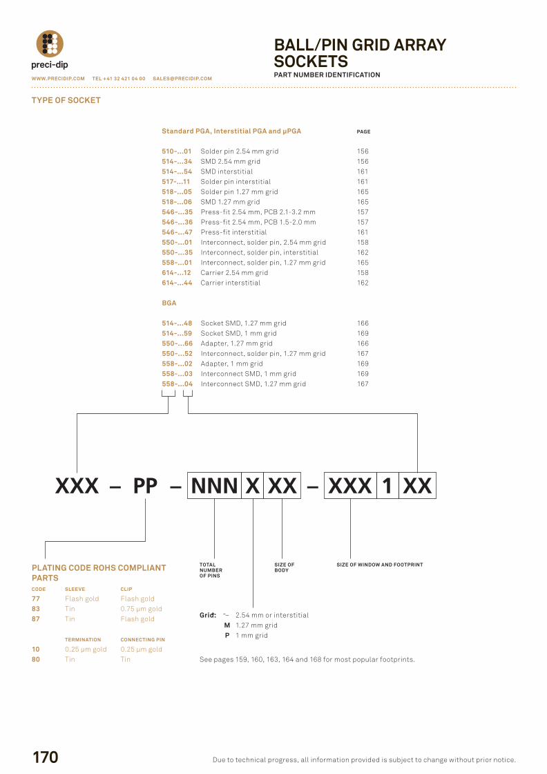
BALL/PIN GRID ARRAYSOCKETSPART NUmBER IDENTIFICATION
TYPE OF SOCKET
Standard PGA, Interstitial PGA and µPGA PAGE
510-...01 solder pin 2.54 mm grid 156 514-...34 sMd 2.54 mm grid 156 514-...54 sMd interstitial 161 517-...11 solder pin interstitial 161 518-...05 solder pin 1.27 mm grid 165 518-...06 sMd 1.27 mm grid 165 546-...35 press-fit 2.54 mm, pcB 2.1-3.2 mm 157 546-...36 press-fit 2.54 mm, pcB 1.5-2.0 mm 157 546-...47 press-fit interstitial 161 550-...01 interconnect, solder pin, 2.54 mm grid 158 550-...35 interconnect, solder pin, interstitial 162 558-...01 interconnect, solder pin, 1.27 mm grid 165 614-...12 carrier 2.54 mm grid 158 614-...44 carrier interstitial 162
BGA
514-...48 socket sMd, 1.27 mm grid 166 514-...59 socket sMd, 1 mm grid 169 550-...66 adapter, 1.27 mm grid 166 550-...52 interconnect, solder pin, 1.27 mm grid 167 558-...02 adapter, 1 mm grid 169 558-...03 interconnect sMd, 1 mm grid 169 558-...04 interconnect sMd, 1.27 mm grid 167
˜ ˜
XXX – PP – NNN X XX – XXX 1 XX
PLATING CODE ROHS COmPLIANT PARTSCODE SLEEvE CLIP
77 flash gold flash gold83 tin 0.75 µm gold87 tin flash gold
TERmINATION CONNECTING PIN
10 0.25 µm gold 0.25 µm gold80 tin tin
TOTALNUmBEROF PINS
SIzE OFBODY
SIzE OF WINDOW AND FOOTPRINT
Grid: – 2.54 mm or interstitial m 1.27 mm grid P 1 mm grid
see pages 159, 160, 163, 164 and 168 for most popular footprints.
P156P173.indd 170 23.08.12 10:15
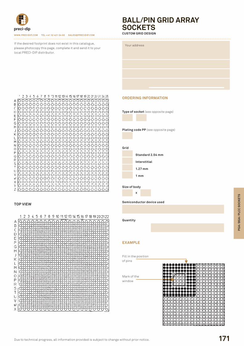
ORDERING INFORmATION
Type of socket (see opposite page)
Plating code PP (see opposite page)
Grid
Standard 2.54 mm
Interstitial
1.27 mm
1 mm
Size of body
x
Semiconductor device used
Quantity
EXAmPLE
fill in the positionof pins
Mark of thewindow
WWW.PRECIDIP.COm TEL +41 32 421 04 00 [email protected]
171
PG
A /
BG
A /
PLC
C S
OC
KE
TS
due to technical progress, all information provided is subject to change without prior notice.
BALL/PIN GRID ARRAYSOCKETS CUSTOm GRID DESIGN
if the desired footprint does not exist in this catalogue,please photocopy this page, complete it and send it to yourlocal preci-dip distributor.
your address
TOP vIEW
P156P173.indd 171 23.08.12 10:15


![TEE Sockets API Specification v1.0 - GlobalPlatform · TEE Sockets API Specification Annex A: TCP/IP Specification of TEE Sockets API Specification [Sockets TCP/IP] GPD_SPE_102 :](https://img.pdfslide.us/doc/110x75/60421070f2b21560856dea9a/tee-sockets-api-specification-v10-globalplatform-tee-sockets-api-specification.jpg)