Embed Size (px)
Citation preview
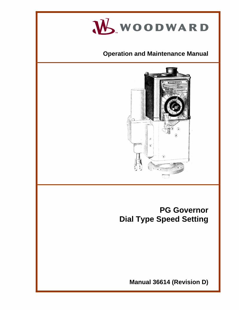
Operation and Maintenance Manual
PG Governor Dial Type Speed Setting
Manual 36614 (Revision D)
WARNING—DANGER OF DEATH OR PERSONAL INJURY
WARNING—FOLLOW INSTRUCTIONS Read this entire manual and all other publications pertaining to the work to be performed before installing, operating, or servicing this equipment. Practice all plant and safety instructions and precautions. Failure to follow instructions can cause personal injury and/or property damage.
WARNING—OUT-OF-DATE PUBLICATION This publication may have been revised or updated since this copy was produced. To verify that you have the latest revision, be sure to check the Woodward website:
www.woodward.com/pubs/current.pdf The revision level is shown at the bottom of the front cover after the publication number. The latest version of most publications is available at:
www.woodward.com/publications If your publication is not there, please contact your customer service representative to get the latest copy.
WARNING—OVERSPEED PROTECTION The engine, turbine, or other type of prime mover should be equipped with an overspeed shutdown device to protect against runaway or damage to the prime mover with possible personal injury, loss of life, or property damage. The overspeed shutdown device must be totally independent of the prime mover control system. An overtemperature or overpressure shutdown device may also be needed for safety, as appropriate.
WARNING—PROPER USE Any unauthorized modifications to or use of this equipment outside its specified mechanical, electrical, or other operating limits may cause personal injury and/or property damage, including damage to the equipment. Any such unauthorized modifications: (i) constitute "misuse" and/or "negligence" within the meaning of the product warranty thereby excluding warranty coverage for any resulting damage, and (ii) invalidate product certifications or listings.
CAUTION—POSSIBLE DAMAGE TO EQUIPMENT OR PROPERTY
CAUTION—BATTERY CHARGING To prevent damage to a control system that uses an alternator or battery-charging device, make sure the charging device is turned off before disconnecting the battery from the system.
CAUTION—ELECTROSTATIC DISCHARGE Electronic controls contain static-sensitive parts. Observe the following precautions to prevent damage to these parts. • Discharge body static before handling the control (with power to the control turned off,
contact a grounded surface and maintain contact while handling the control). • Avoid all plastic, vinyl, and Styrofoam (except antistatic versions) around printed circuit
boards. • Do not touch the components or conductors on a printed circuit board with your hands
or with conductive devices.
IMPORTANT DEFINITIONS • A WARNING indicates a potentially hazardous situation which, if not avoided, could result in
death or serious injury. • A CAUTION indicates a potentially hazardous situation which, if not avoided, could result in
damage to equipment or property. • A NOTE provides other helpful information that does not fall under the warning or caution
categories. Revisions—Text changes are indicated by a black line alongside the text. Woodward Governor Company reserves the right to update any portion of this publication at any time. Information provided by Woodward Governor Company is believed to be correct and reliable. However, no responsibility is assumed by Woodward Governor Company unless otherwise expressly undertaken.
© Woodward 1967 All Rights Reserved
Manual 36614 PG Governor Dial Type Speed Setting
Woodward i
Contents
REGULATORY COMPLIANCE......................................................................... II CHAPTER 1. GENERAL INFORMATION........................................................... 1 General ...................................................................................................................1 Operation................................................................................................................1 CHAPTER 2. MAINTENANCE ......................................................................... 2 Introduction.............................................................................................................2 Disassembly ...........................................................................................................2 Cleaning .................................................................................................................2 Parts Check ............................................................................................................3 Assembly ................................................................................................................3 Speed Limit Adjustment..........................................................................................4 CHAPTER 3. REPLACEMENT PARTS ............................................................. 7 Replacement Parts Information..............................................................................7 Illustrated Parts Breakdown ...................................................................................7 CHAPTER 4. SERVICE OPTIONS ................................................................... 9 Product Service Options.........................................................................................9 Returning Equipment for Repair...........................................................................10 Replacement Parts ...............................................................................................11 How to Contact Woodward...................................................................................11 Engineering Services ...........................................................................................12 Technical Assistance............................................................................................13 DECLARATIONS......................................................................................... 14
Illustrations and Tables Figure 1-1. Schematic Diagram, PG Dial Speed Setting .......................................1 Figure 2-1. Column Removal .................................................................................3 Figure 2-2. Speed Adjustment Knob Removal.......................................................4 Figure 2-3. Holding Speed Adjusting Shaft ............................................................5 Figure 2-4. Disengagement of Indicator Gear........................................................5 Figure 3-1. Exploded View, PG Dial Speed Setting ...............................................8
PG Governor Dial Type Speed Setting Manual 36614
ii Woodward
Regulatory Compliance European Compliance for CE Marking: These listings are limited only to those units bearing the CE Marking. ATEX – Potentially Declared to 94/9/EEC COUNCIL DIRECTIVE of 23 Explosive March 1994 on the approximation of the laws of the Atmospheres Member States concerning equipment and Directive: protective systems intended for use in potentially
explosive atmospheres. Zone 1, Category 2, Group II G, c II T3 Other European and International Compliance: Compliance with the following European Directives or standards does not qualify this product for application of the CE Marking: Machinery Directive: Compliant as a component with 98/37/EC COUNCIL
DIRECTIVE of 23 July 1998 on the approximation of the laws of the Member States relating to machinery.
Pressure Equipment Compliant as “SEP” per Article 3.3 to Pressure Directive: Equipment Directive 97/23/EC of 29 May 1997 on
the approximation of the laws of the Member States concerning pressure equipment.
WARNING—EXPLOSION HAZARD Substitution of components may impair suitability for Zone 1.
Manual 36614 PG Governor Dial Type Speed Setting
Woodward 1
Chapter 1. General Information
General This manual covers operation, maintenance and a replacement parts list for the dial-type speed setting for short-column PG governors. This type speed setting (one of many arrangements available for use on PG governors) allows a precise means of manually adjusting speed at the governor. Additional manuals cover other components of the PG governor. Refer to manual 54056, PG Dial and Lever Governor Installation, for installation instructions and safety information.
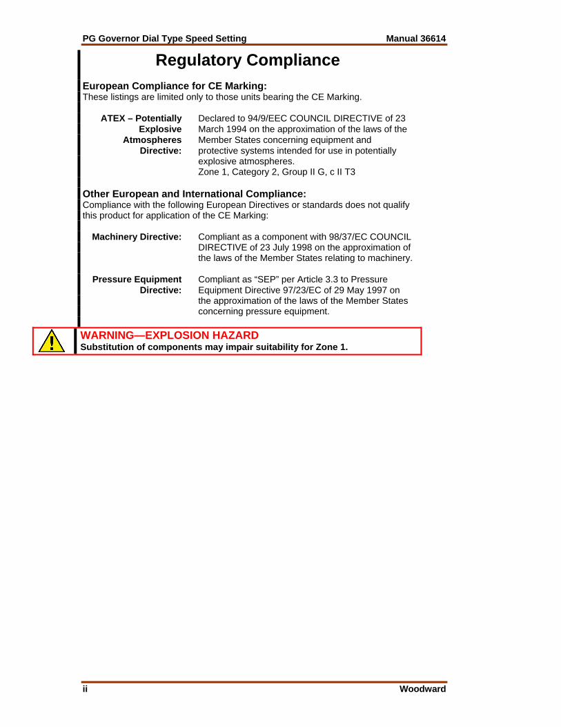
Operation Refer to the schematic diagram (Figure 1-1). The governor speed setting is determined by the compression of the speeder spring. The speeder spring compression is determined by the position of the speeder plug, which is raised or lowered by rotation of the speed setting knob. Refer to the Woodward manual 36600, PG Governor Basic Elements, for a description of the effect of a speed setting change on the operation of the basic elements.
WARNING—OVERSPEED PROTECTION The engine, turbine, or other type of prime mover should be equipped with an overspeed shutdown device to protect against runaway or damage to the prime mover with possible personal injury, loss of life, or property damage.
The overspeed shutdown device must be totally independent of the prime mover control system. An overtemperature or overpressure shutdown device may also be needed for safety, as appropriate.
Figure 1-1. Schematic Diagram, PG Dial Speed Setting
PG Governor Dial Type Speed Setting Manual 36614
2 Woodward
Chapter 2. Maintenance
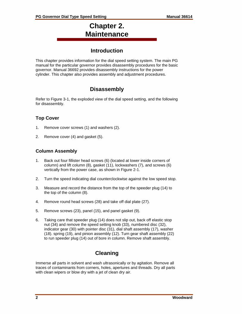
Introduction This chapter provides information for the dial speed setting system. The main PG manual for the particular governor provides disassembly procedures for the basic governor. Manual 36692 provides disassembly instructions for the power cylinder. This chapter also provides assembly and adjustment procedures.
Disassembly Refer to Figure 3-1, the exploded view of the dial speed setting, and the following for disassembly. Top Cover 1. Remove cover screws (1) and washers (2). 2. Remove cover (4) and gasket (5). Column Assembly 1. Back out four fillister head screws (6) (located at lower inside corners of
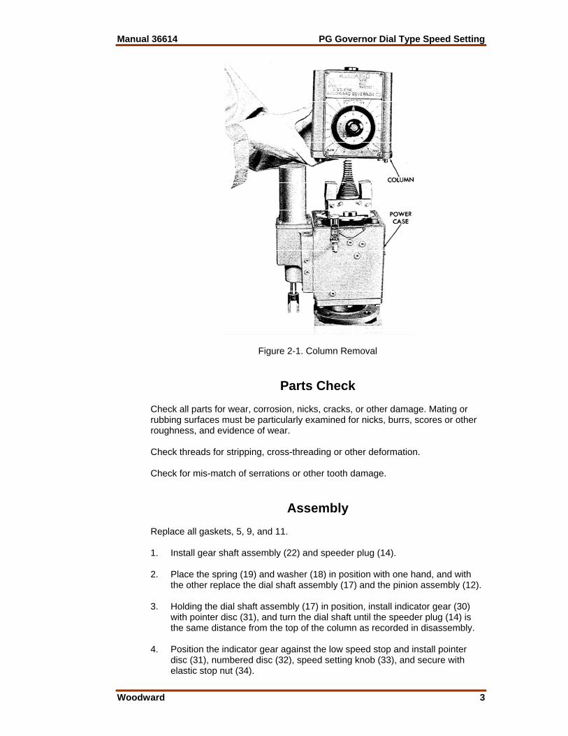
column) and lift column (8), gasket (11), lockwashers (7), and screws (6) vertically from the power case, as shown in Figure 2-1.
2. Turn the speed indicating dial counterclockwise against the low speed stop. 3. Measure and record the distance from the top of the speeder plug (14) to
the top of the column (8). 4. Remove round head screws (28) and take off dial plate (27). 5. Remove screws (23), panel (15), and panel gasket (9). 6. Taking care that speeder plug (14) does not slip out, back off elastic stop
nut (34) and remove the speed setting knob (33), numbered disc (32), indicator gear (30) with pointer disc (31), dial shaft assembly (17), washer (18). spring (19), and pinion assembly (12). Turn gear shaft assembly (22) to run speeder plug (14) out of bore in column. Remove shaft assembly.
Cleaning Immerse all parts in solvent and wash ultrasonically or by agitation. Remove all traces of contaminants from corners, holes, apertures and threads. Dry all parts with clean wipers or blow dry with a jet of clean dry air.
Manual 36614 PG Governor Dial Type Speed Setting
Woodward 3
Figure 2-1. Column Removal
Parts Check Check all parts for wear, corrosion, nicks, cracks, or other damage. Mating or rubbing surfaces must be particularly examined for nicks, burrs, scores or other roughness, and evidence of wear. Check threads for stripping, cross-threading or other deformation. Check for mis-match of serrations or other tooth damage.
Assembly Replace all gaskets, 5, 9, and 11. 1. Install gear shaft assembly (22) and speeder plug (14). 2. Place the spring (19) and washer (18) in position with one hand, and with
the other replace the dial shaft assembly (17) and the pinion assembly (12). 3. Holding the dial shaft assembly (17) in position, install indicator gear (30)
with pointer disc (31), and turn the dial shaft until the speeder plug (14) is the same distance from the top of the column as recorded in disassembly.
4. Position the indicator gear against the low speed stop and install pointer
disc (31), numbered disc (32), speed setting knob (33), and secure with elastic stop nut (34).
PG Governor Dial Type Speed Setting Manual 36614
4 Woodward
5. Replace dial plate (27) with round head screws (28). 6. Install panel (15) and new gasket (9) with screws (23). 7. Install new case-column gasket (11). 8. Place lockwashers (7) and fillister head screws (6) in holes in lower flange
of the column (8). Align speeder spring check plug (shown in manual 36600 or 36602) so that it will seat properly in the bore in the speeder plug. Align dowel pins (in column) with the holes in the power case and place the column on the power case. Fasten with screws (6) and lockwashers (7).
9. Install cover (4) with new gasket (5). Secure with screws (1) and
lockwashers (2).
Speed Limit Adjustment When changing speed setting adjustments or the pointer indication, use the following procedure. Do not make these adjustments unless the linkage from the governor to the engine fuel racks (or metering valve) has been properly adjusted. Make certain that the engine is at idle speed or lower when the governor is set for low speed.
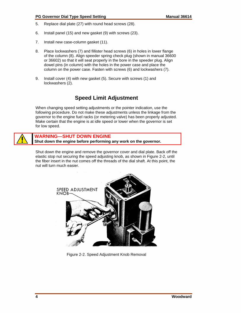
WARNING—SHUT DOWN ENGINE Shut down the engine before performing any work on the governor. Shut down the engine and remove the governor cover and dial plate. Back off the elastic stop nut securing the speed adjusting knob, as shown in Figure 2-2, until the fiber insert in the nut comes off the threads of the dial shaft. At this point, the nut will turn much easier.
Figure 2-2. Speed Adjustment Knob Removal
Manual 36614 PG Governor Dial Type Speed Setting
Woodward 5
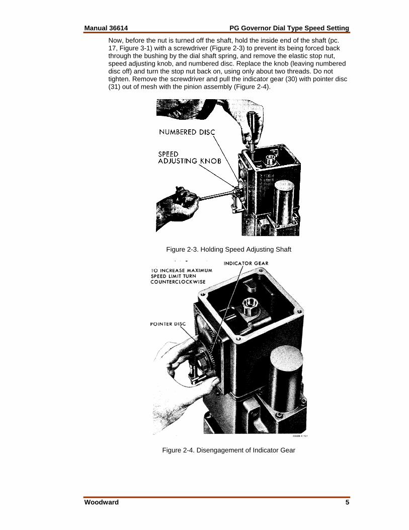
Now, before the nut is turned off the shaft, hold the inside end of the shaft (pc. 17, Figure 3-1) with a screwdriver (Figure 2-3) to prevent its being forced back through the bushing by the dial shaft spring, and remove the elastic stop nut, speed adjusting knob, and numbered disc. Replace the knob (leaving numbered disc off) and turn the stop nut back on, using only about two threads. Do not tighten. Remove the screwdriver and pull the indicator gear (30) with pointer disc (31) out of mesh with the pinion assembly (Figure 2-4).
Figure 2-3. Holding Speed Adjusting Shaft
Figure 2-4. Disengagement of Indicator Gear
PG Governor Dial Type Speed Setting Manual 36614
6 Woodward
WARNING—START-UP Be prepared to make an emergency shutdown when starting the engine, turbine, or other type of prime mover, to protect against runaway or overspeed with possible personal injury, loss of life, or property damage. Start the engine and adjust to the desired high speed with the knob. Re-mesh the indicator gear with the high speed stop pin of the indicator gear against the stop pin (24) in the face of the panel. Replace the dial plate to check the pointer reading. If the pointer does not indicate the desired position on the dial plate, pry the pointer disc off and reposition it on the indicator gear. Check the low speed by turning the speed adjusting knob until it contacts the low speed stop. (On dials calibrated in rpm, an error of 10% between engine speed and pointer reading may be expected at low speed.) When the desired high and low speeds have been obtained, shut down the engine, remove the elastic stop nut and speed adjusting knob as before. Be sure to hold a screwdriver behind dial shaft when removing elastic stop nut and knob. Reassemble numbered disc, knob, and elastic stop nut. Tighten the nut.
Manual 36614 PG Governor Dial Type Speed Setting
Woodward 7
Chapter 3. Replacement Parts
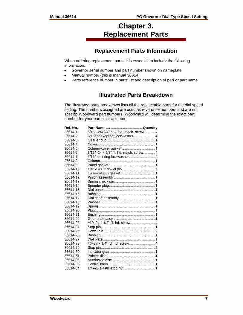
Replacement Parts Information When ordering replacement parts, it is essential to include the following information: • Governor serial number and part number shown on nameplate • Manual number (this is manual 36614) • Parts reference number in parts list and description of part or part name
Illustrated Parts Breakdown The illustrated parts breakdown lists all the replaceable parts for the dial speed setting. The numbers assigned are used as reverence numbers and are not specific Woodward part numbers. Woodward will determine the exact part number for your particular actuator. Ref. No. Part Name .................................... Quantity 36614-1 5/16”–24x3/4” hex. hd. mach. screw ..........4 36614-2 5/16” shakeproof lockwasher......................4 36614-3 Oil filler cup ................................................1 36614-4 Cover..........................................................1 36614-5 Column-cover gasket .................................1 36614-6 5/16”–24 x 5/8” fil. hd. mach. screw............4 36614-7 5/16” split ring lockwasher..........................4 36614-8 Column.......................................................1 36614-9 Panel gasket ..............................................1 36614-10 1/4” x 9/16” dowel pin .................................2 36614-11 Case-column gasket...................................1 36614-12 Pinion assembly .........................................1 36614-13 Spring check pin.........................................1 36614-14 Speeder plug..............................................1 36614-15 Dial panel ...................................................1 36614-16 Bushing ......................................................1 36614-17 Dial shaft assembly ....................................1 36614-18 Washer.......................................................1 36614-19 Spring.........................................................1 36614-20 Plug............................................................1 36614-21 Bushing ......................................................1 36614-22 Gear shaft assy. .........................................1 36614-23 #10–24 x 1/2” fil. hd. screw ........................4 36614-24 Stop pin ......................................................1 36614-25 Dowel pin ...................................................2 36614-26 Bushing ......................................................1 36614-27 Dial plate ....................................................1 36614-28 #6–32 x 1/4” rd. hd. screw..........................4 36614-29 Stop pin ......................................................2 36614-30 Indicator gear .............................................1 36614-31 Pointer disc ................................................1 36614-32 Numbered disc ...........................................1 36614-33 Control knob...............................................1 36614-34 1/4–20 elastic stop nut ...............................1
PG Governor Dial Type Speed Setting Manual 36614
8 Woodward
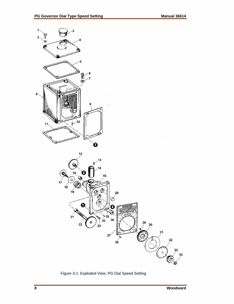
Figure 3-1. Exploded View, PG Dial Speed Setting
Manual 36614 PG Governor Dial Type Speed Setting
Woodward 9
Chapter 4. Service Options
Product Service Options The following factory options are available for servicing Woodward equipment, based on the standard Woodward Product and Service Warranty (5-01-1205) that is in effect at the time the product is purchased from Woodward or the service is performed: • Replacement/Exchange (24-hour service) • Flat Rate Repair • Flat Rate Remanufacture If you are experiencing problems with installation or unsatisfactory performance of an installed system, the following options are available: • Consult the troubleshooting guide in the manual. • Contact Woodward technical assistance (see “How to Contact Woodward”
later in this chapter) and discuss your problem. In most cases, your problem can be resolved over the phone. If not, you can select which course of action you wish to pursue based on the available services listed in this section.
Replacement/Exchange Replacement/Exchange is a premium program designed for the user who is in need of immediate service. It allows you to request and receive a like-new replacement unit in minimum time (usually within 24 hours of the request), providing a suitable unit is available at the time of the request, thereby minimizing costly downtime. This is also a flat rate structured program and includes the full standard Woodward product warranty (Woodward Product and Service Warranty 5-01-1205). This option allows you to call in the event of an unexpected outage, or in advance of a scheduled outage, to request a replacement control unit. If the unit is available at the time of the call, it can usually be shipped out within 24 hours. You replace your field control unit with the like-new replacement and return the field unit to the Woodward facility as explained below (see “Returning Equipment for Repair” later in this chapter). Charges for the Replacement/Exchange service are based on a flat rate plus shipping expenses. You are invoiced the flat rate replacement/exchange charge plus a core charge at the time the replacement unit is shipped. If the core (field unit) is returned to Woodward within 60 days, Woodward will issue a credit for the core charge. [The core charge is the average difference between the flat rate replacement/exchange charge and the current list price of a new unit.] Return Shipment Authorization Label. To ensure prompt receipt of the core, and avoid additional charges, the package must be properly marked. A return authorization label is included with every Replacement/Exchange unit that leaves Woodward. The core should be repackaged and the return authorization label affixed to the outside of the package. Without the authorization label, receipt of the returned core could be delayed and cause additional charges to be applied.
PG Governor Dial Type Speed Setting Manual 36614
10 Woodward
Flat Rate Repair Flat Rate Repair is available for the majority of standard products in the field. This program offers you repair service for your products with the advantage of knowing in advance what the cost will be. All repair work carries the standard Woodward service warranty (Woodward Product and Service Warranty 5-01-1205) on replaced parts and labor. Flat Rate Remanufacture Flat Rate Remanufacture is very similar to the Flat Rate Repair option with the exception that the unit will be returned to you in “like-new” condition and carry with it the full standard Woodward product warranty (Woodward Product and Service Warranty 5-01-1205). This option is applicable to mechanical products only.
Returning Equipment for Repair If a control (or any part of an electronic control) is to be returned to Woodward for repair, please contact Woodward in advance to obtain a Return Authorization Number. When shipping the item(s), attach a tag with the following information: • name and location where the control is installed; • name and phone number of contact person; • complete Woodward part number(s) and serial number(s); • description of the problem; • instructions describing the desired type of repair.
CAUTION—ELECTROSTATIC DISCHARGE To prevent damage to electronic components caused by improper handling, read and observe the precautions in Woodward manual 82715, Guide for Handling and Protection of Electronic Controls, Printed Circuit Boards, and Modules. Packing a Control Use the following materials when returning a complete control: • protective caps on any connectors; • antistatic protective bags on all electronic modules; • packing materials that will not damage the surface of the unit; • at least 100 mm (4 inches) of tightly packed, industry-approved packing
material; • a packing carton with double walls; • a strong tape around the outside of the carton for increased strength.
Manual 36614 PG Governor Dial Type Speed Setting
Woodward 11
Return Authorization Number When returning equipment to Woodward, please telephone and ask for the Customer Service Department [1 (800) 523-2831 in North America or +1 (970) 482-5811]. They will help expedite the processing of your order through our distributors or local service facility. To expedite the repair process, contact Woodward in advance to obtain a Return Authorization Number, and arrange for issue of a purchase order for the item(s) to be repaired. No work can be started until a purchase order is received.
NOTE We highly recommend that you make arrangement in advance for return shipments. Contact a Woodward customer service representative at 1 (800) 523-2831 in North America or +1 (970) 482-5811 for instructions and for a Return Authorization Number.
Replacement Parts When ordering replacement parts for controls, include the following information: • the part number(s) (XXXX-XXXX) that is on the enclosure nameplate; • the unit serial number, which is also on the nameplate.
How to Contact Woodward In North America use the following address when shipping or corresponding: Woodward Governor Company PO Box 1519 1000 East Drake Rd Fort Collins CO 80522-1519, USA Telephone—+1 (970) 482-5811 (24 hours a day) Toll-free Phone (in North America)—1 (800) 523-2831 Fax—+1 (970) 498-3058 For assistance outside North America, call one of the following international Woodward facilities to obtain the address and phone number of the facility nearest your location where you will be able to get information and service. Facility Phone Number Brazil +55 (19) 3708 4800 India +91 (129) 230 7111 Japan +81 (476) 93-4661 The Netherlands +31 (23) 5661111 You can also contact the Woodward Customer Service Department or consult our worldwide directory on Woodward’s website (www.woodward.com) for the name of your nearest Woodward distributor or service facility.
PG Governor Dial Type Speed Setting Manual 36614
12 Woodward
Engineering Services Woodward Industrial Controls Engineering Services offers the following after-sales support for Woodward products. For these services, you can contact us by telephone, by email, or through the Woodward website. • Technical Support • Product Training • Field Service Contact information: Telephone—+1 (970) 482-5811 Toll-free Phone (in North America)—1 (800) 523-2831 Email—[email protected] Website—www.woodward.com Technical Support is available through our many worldwide locations or our authorized distributors, depending upon the product. This service can assist you with technical questions or problem solving during normal business hours. Emergency assistance is also available during non-business hours by phoning our toll-free number and stating the urgency of your problem. For technical support, please contact us via telephone, email us, or use our website and reference Customer Services and then Technical Support. Product Training is available at many of our worldwide locations (standard classes). We also offer customized classes, which can be tailored to your needs and can be held at one of our locations or at your site. This training, conducted by experienced personnel, will assure that you will be able to maintain system reliability and availability. For information concerning training, please contact us via telephone, email us, or use our website and reference Customer Services and then Product Training. Field Service engineering on-site support is available, depending on the product and location, from one of our many worldwide locations or from one of our authorized distributors. The field engineers are experienced both on Woodward products as well as on much of the non-Woodward equipment with which our products interface. For field service engineering assistance, please contact us via telephone, email us, or use our website and reference Customer Services and then Technical Support.
Manual 36614 PG Governor Dial Type Speed Setting
Woodward 13
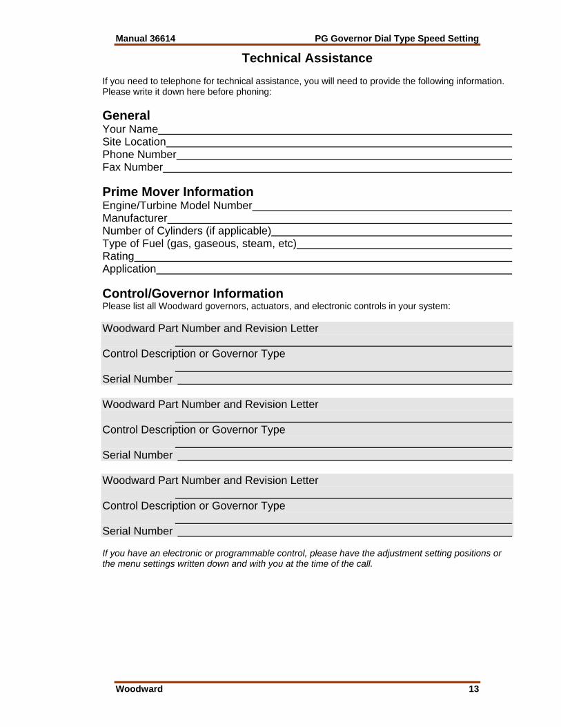
Technical Assistance If you need to telephone for technical assistance, you will need to provide the following information. Please write it down here before phoning: General Your Name Site Location Phone Number Fax Number Prime Mover Information Engine/Turbine Model Number Manufacturer Number of Cylinders (if applicable) Type of Fuel (gas, gaseous, steam, etc) Rating Application Control/Governor Information Please list all Woodward governors, actuators, and electronic controls in your system: Woodward Part Number and Revision Letter Control Description or Governor Type Serial Number Woodward Part Number and Revision Letter Control Description or Governor Type Serial Number Woodward Part Number and Revision Letter Control Description or Governor Type Serial Number If you have an electronic or programmable control, please have the adjustment setting positions or the menu settings written down and with you at the time of the call.
Declarations

We appreciate your comments about the content of our publications.
Send comments to: [email protected]
Please include the manual number from the front cover of this publication.
PO Box 1519, Fort Collins CO 80522-1519, USA 1000 East Drake Road, Fort Collins CO 80525, USA Phone +1 (970) 482-5811 • Fax +1 (970) 498-3058
Email and Website—www.woodward.com
Woodward has company-owned plants, subsidiaries, and branches, as well as authorized distributors and other authorized service and sales facilities throughout the world.
Complete address / phone / fax / email information for all locations is available on our website.
06/10/F


![CUBE Media Proxy - Cisco · media-recording proxy [dial-peer-tag1 dial-peer-tag2 dial-peer-tag3 dial-peer-tag4 dial-peer-tag5] Example: Step4 Note Youcanspecifymaximumoffivedial-peertags](https://img.pdfslide.us/doc/110x75/600896c15662324ac908e474/cube-media-proxy-cisco-media-recording-proxy-dial-peer-tag1-dial-peer-tag2-dial-peer-tag3.jpg)