Embed Size (px)
Citation preview
For Your Safe Flight Page 1
Pilot’s GuideEngine Data Management
EDM-730EDM-830EDM-740EXPERIMENTAL
Copyright � 2000-2010 J.P. Instruments, Inc.
All Rights Reserved
J.P. INSTRUMENTS INC.Information: P. O. Box 7033Huntington Beach, CA 92646
Factory: 3185 B AirwayCosta Mesa, CA 92626
PH: (714) 557-5434PH: (800) 345-4574FX: (714) [email protected]
Printed in the United States of America Rev C June 1 2010Last printed 3/11/2011 8:44:00 AM
Page 2 Engine Data Management
Table of Contents
Section 1 - Introduction 5Product Features 5Engine Data Management 6Benefits of Proper Mixture Control 6JPI Probes 6Temperature and Mixture 6Displays and Controls 8Typical EDM-830-6C Cylinder Display 8Typical display configurations by model and mounting orientation 12EDM-830 RPM and MAP Display 13EDM-730/830 Linear Gauges 13EDM-730/830 Basic Scanner® Operation 14Operating Modes 15Button Location and Display Rotation 16Scanner® Information Area 19
Section 2 - Operating Procedures 20Built-in Diagnostics: Startup and During Flight 20EDM Modes 20Automatic Mode 20Manual Mode 21LeanFind Mode 22LeanFind Procedure—General Explanation 25Expanded Leaning Procedures 28Operation for each Phase of Flight 29Shock Cooling 30Common Misapplications 31
Section 3 - Diagnosing Engine Problems 32Engine Diagnosis Chart 33Alarms 35Alarm Priority 36Pre-Ignition and Detonation 36
Section 4 - Fuel Flow Option Operation 37Fuel Management 37Start Up Fuel 38Resetting ‘USED’ 42Accumulate — Trip Totalizer 42Fuel Flow Display Select Switch 42Parameter Scan—Systems with Fuel Flow Option 42
Section 5 - Long Term Data Memory 44Downloading from Long Term Memory 44Transferring from the USB Flash Drive to a PC 45

For Your Safe Flight Page 3
Section 6 - Personalizing 45Pilot Programming 45
Section 7 - Programming Horsepower Constant 47Section 8 - Programming Manifold Pressure (MAP) 47Section 9 - Programming use of Factory Original TIT Probe 48Section 10 - Programming the Fuel Flow Option 49Section 11 - Programming Long Term Data Memory 51Section 12 - Factory Limits and GPS 52MAP, Fuel Flow Alarm Limits, Units, Fuel Capacity 55Navigation GPS Data Formats 57GPS-C Fuel Flow Format for GPS Bi-directional Comm 57Navigation Data Ports for GPS Communication 58
Section 13 - Options Connector Pin Assignments 59Section 14 - Display Customization 60Section 15 - Reference Reading 61Section 16 - Technical Support 61Section 17 - Limited Warranty 62Section 18 - EDM-851 TWIN ENGINE ADDENDUM 63Section 19 - Index 64QUICK REFERENCE GUIDE 68

Page 4 Engine Data Management
The following is a quick reference of basic operation
AUTO MODE:parameters
automaticallyindexed
Toggles toinclude/exclude
parameter inAUTO MODE
indexing
LEAN FIND:starts LeanFind
procedure
Toggle betweenLEAN R and
LEAN L of peak
Cylinder I.D.box flashes
see‘LeanFindMode’ for
details
Displayspeak EGT
value
tap STEP button
tap LF, then tap STEP
tap STEP and LFsimultaneously
release buttons
LFLF
STEP
hold
both
STEPan
d LF
simult
aneo
usly
beginleaning continueleaning
hold LF
release LF
MANUAL MODE:Parameters
manually indexedby tapping STEP
For Your Safe Flight Page 5
Section 1 - Introduction
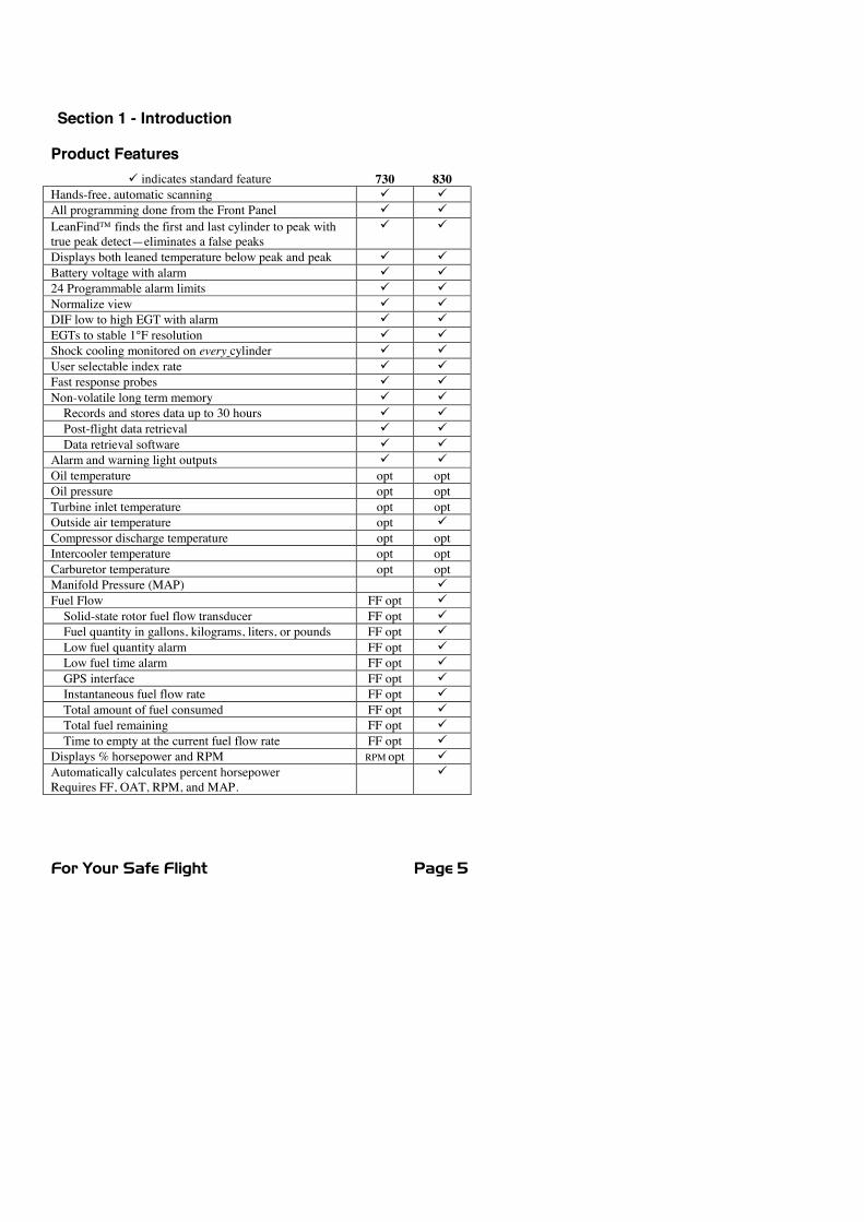
Product Features9 indicates standard feature 730 830
Hands-free, automatic scanning 9 9All programming done from the Front Panel 9 9LeanFind� finds the first and last cylinder to peak withtrue peak detect—eliminates a false peaks
9 9
Displays both leaned temperature below peak and peak 9 9Battery voltage with alarm 9 924 Programmable alarm limits 9 9Normalize view 9 9DIF low to high EGT with alarm 9 9EGTs to stable 1°F resolution 9 9Shock cooling monitored on every cylinder 9 9User selectable index rate 9 9Fast response probes 9 9Non-volatile long term memory 9 9Records and stores data up to 30 hours 9 9Post-flight data retrieval 9 9Data retrieval software 9 9
Alarm and warning light outputs 9 9Oil temperature opt optOil pressure opt optTurbine inlet temperature opt optOutside air temperature opt 9Compressor discharge temperature opt optIntercooler temperature opt optCarburetor temperature opt optManifold Pressure (MAP) 9Fuel Flow FF opt 9Solid-state rotor fuel flow transducer FF opt 9Fuel quantity in gallons, kilograms, liters, or pounds FF opt 9Low fuel quantity alarm FF opt 9Low fuel time alarm FF opt 9GPS interface FF opt 9Instantaneous fuel flow rate FF opt 9Total amount of fuel consumed FF opt 9Total fuel remaining FF opt 9Time to empty at the current fuel flow rate FF opt 9
Displays % horsepower and RPM RPM opt 9Automatically calculates percent horsepowerRequires FF, OAT, RPM, and MAP.
9
Page 6 Engine Data Management
Engine Data ManagementThe EDM Engine Data Management system is the most advanced andaccurate piston engine-monitoring instrument on the market. Using thelatest microprocessor technology, the EDM will monitor up to twenty-four critical parameters in your engine, four times a second, with alinearized thermocouple accuracy of better than 0.1 percent or 2 F°.As your built-in flight engineer, the EDM is constantly “red line”checking: all critical parameters are automatically checked four times asecond, regardless of the current display status. Leaning is accomplishedquickly and automatically using the LeanFind� procedure. With theEDM, it is now possible to have substantially more diagnosticinformation available to you in a timely and usable manner.
Benefits of Proper Mixture Controlx Improved engine efficiency x Reduced maintenance costsx Greater fuel economy x Reduced operating costsx Smoother engine operation x Proper engine temperaturesx Longer spark plug life x Reduced engine vibration
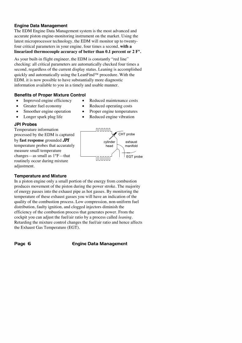
JPI ProbesTemperature informationprocessed by the EDM is capturedby fast response grounded JPItemperature probes that accuratelymeasure small temperaturechanges—as small as 1°F—thatroutinely occur during mixtureadjustment.
Temperature and MixtureIn a piston engine only a small portion of the energy from combustionproduces movement of the piston during the power stroke. The majorityof energy passes into the exhaust pipe as hot gasses. By monitoring thetemperature of these exhaust gasses you will have an indication of thequality of the combustion process. Low compression, non-uniform fueldistribution, faulty ignition, and clogged injectors diminish theefficiency of the combustion process that generates power. From thecockpit you can adjust the fuel/air ratio by a process called leaning.Retarding the mixture control changes the fuel/air ratio and hence affectsthe Exhaust Gas Temperature (EGT).
CHT probe
EGT probe
cylinderhead
exhaustmanifold
For Your Safe Flight Page 7
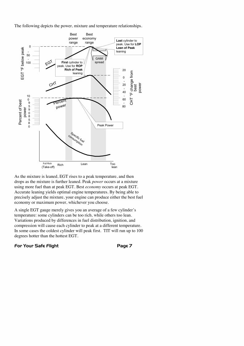
The following depicts the power, mixture and temperature relationships.EGT°Fbelowpeak
Percentofbest
power
CHT°Fchangefrom
best
power
Bestpowerrange
0
-100
-50
-20
20
-60
-40
0
-80
100
85
90
95
80
Percent
power
Specific fuel
consumption
Toolean
LeanRichFull Rich
(Take-off)
EGT
CHT
First cylinder topeak. Use for ROP
Rich of Peakleaning
Last cylinder topeak. Use for LOPLean of Peakleaning
Peak Power
Besteconomyrange
GAMIspread
As the mixture is leaned, EGT rises to a peak temperature, and thendrops as the mixture is further leaned. Peak power occurs at a mixtureusing more fuel than at peak EGT. Best economy occurs at peak EGT.Accurate leaning yields optimal engine temperatures. By being able toprecisely adjust the mixture, your engine can produce either the best fueleconomy or maximum power, whichever you choose.
A single EGT gauge merely gives you an average of a few cylinder’stemperature: some cylinders can be too rich, while others too lean.Variations produced by differences in fuel distribution, ignition, andcompression will cause each cylinder to peak at a different temperature.In some cases the coldest cylinder will peak first. TIT will run up to 100degrees hotter than the hottest EGT.
Page 8 Engine Data Management
Displays and ControlsThe EDM monitors engine temperatures and voltages, assists inadjusting the fuel/air mixture, and helps diagnose engine malfunctions.There are three components of the user interface:
x Analog display including cylinder number and cylinder I.D. boxx Digital display for numeric readouts and messagesx Two front panel operating buttons for simple operation.
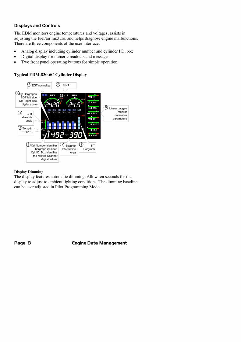
Typical EDM-830-6C Cylinder Display
TITBargraph
Linear gaugesmonitor
numerousparameters
CHTabsolutescale
Temp in°F or °C
Cyl Number identifiesbargraph cylinder.
Cyl I.D. Box identifiesthe related Scanner
digital values
Cyl Bargraphs:EGT left side,CHT right side,digital above
%HPEGT normalize
ScannerInformation
Area
8
9
7
6
5
4
3
2
1
Display DimmingThe display features automatic dimming. Allow ten seconds for thedisplay to adjust to ambient lighting conditions. The dimming baselinecan be user adjusted in Pilot Programming Mode.
For Your Safe Flight Page 9
The following is a description of various display areas. Numbers incircles refer to features in the above diagram.
1 Normalize View and Percentage Viewx Percentage View: when the EGT normalize indicator ‘NRM’ is
not lit, the columns indicate percent of EGT red line. Eachcolumn is composed of a stack of segments. A maximum heightcolumn (all segments lit) depicts 100 %, or more, of red line anda one segment-high column depicts 50 % of red line. Forexample, if the red line is 1650°F, a maximum height columnrepresents 1650°F and a one segment-high column representshalf that value, or 825°F. The Percentage View permitscomparison of EGTs across all cylinders. Hotter cylindersdisplay higher columns than cooler cylinders.
x Normalize View: when the EGT normalize indicator ‘NRM’ islit, the EGT columns are displayed normalized. When youactivate Normalize View, all column peaks are set to the samehalf-height level for trend analysis. Any changes are shown as anincrease or decrease in column height. A one-segment changein column height represents a 10°F change. The Normalizeview permits rapid visualization of EGT trends, rather than apercentage of red line. You should use normalize in level cruiseand run-up.
To toggle between Percentage View and Normalize View, hold theLF button until the ‘NRM’ indicator either comes on or goes off.Selecting the Normalize view does not affect the digital display nor alterthe parameter sequence. The CHT display—described later—is notaffected by either Normalize or Percentage view.
You may select the Normalize view in either the Manual or Automaticmodes, but not during Lean Find mode. Normalize view is most helpfulfor engine trend monitoring of each cylinder’s operation. For exampleusing the Normalize view during engine run-up, a fouled spark plug willappear as a higher column.
TIP: A common misapplication is to be in the Normalize view and thenchange your power setting. This can cause all columns to go off scale,high or low, giving you the impression there is a problem. Turn off‘NRM’ (return to Percentage view) before adding or reducing power andwhen beginning your descent.
Page 10 Engine Data Management
2 Temperature Units (°F or °C)The EDM series engine temps can be set for either degrees Fahrenheit°F or degrees Celsius °C. Note: OAT units can be set independently ofthe engine temps. To change the display of engine temperatures see“Changing the Alarm Limits” on page 52.
3 Cylinder Numbers and the Cylinder I.D. boxThe row of numbers 1 through 6 (cylinder I.D numbers) and the letter‘T’ (optional turbine inlet temp) are the column labels for the analogdisplay bargraphs. A square box (cylinder I.D. box), surrounding one ormore of the labels, specifies that those particular cylinders relate to thevalues currently shown in the Scanner® information area.
4 CHT absolute scaleThe ‘CHT absolute scale’ allows you to quickly determine the absolutetemperature of any CHT by comparing the bargraph height to the scale.This is a quick and useful way to visually determine your CHTtemperatures relative to redline.
5 Bar Graph EGT and CHTA cylinder ‘bargraph set’ is composed of a dotted line leading from thecylinder I.D. number vertically to its EGT/CHT digital values. The EGTcolumn is located to the left of the line and the CHT column to the right.Columns are composed of a stack of segments. The maximum height fora column is the top of the dotted line. The CHT redline value is depictedby a horizontal red line approximately half way up and to the right of thedotted line. When any CHT column reaches redline, its column will turnred and an alarm message will commence. The CHT display is notaffected by mode or view. The EGT column has three different viewingmodes: Percent View, Normalize View and Lean Find.
6 Percent HP (EDM-830 only)Displays %HP (if FF, RPM, OAT, MAP functional).
7 Scanner® Information AreaThe Scanner® Information Area provides expanded information for thevarious monitored parameters. The Scanner® operates automatically ormanually.
For Your Safe Flight Page 11
8 TIT BargraphThe EDM provides a bargraph display of the hottest TIT andcontinuously checks for exceedance of the redline temp. Once redline isreached, the bargraph will change to red and an alert will flash in theScanner® Information Area.
9 Linear GaugesThe Linear gauges provide both digital and analog indications forvarious parameters. The sliding pointer and color range marks give you aquick indication of where you are relative to the operating limits whilethe digital value provides precise information. See Section 14 - DisplayCustomization for ways you can customize this area. Note: parametersmonitored vary by model and options present.
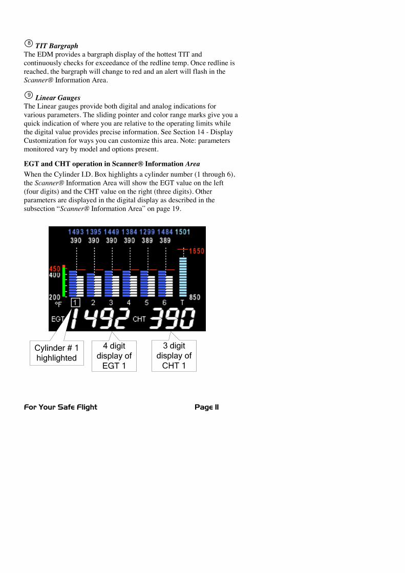
EGT and CHT operation in Scanner® Information AreaWhen the Cylinder I.D. Box highlights a cylinder number (1 through 6),the Scanner® Information Area will show the EGT value on the left(four digits) and the CHT value on the right (three digits). Otherparameters are displayed in the digital display as described in thesubsection “Scanner® Information Area” on page 19.
4 digitdisplay of
EGT 1
3 digitdisplay of
CHT 1
Cylinder # 1highlighted
Page 12 Engine Data Management
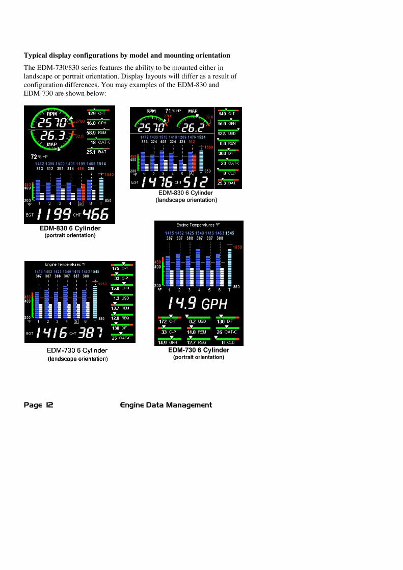
Typical display configurations by model and mounting orientationThe EDM-730/830 series features the ability to be mounted either inlandscape or portrait orientation. Display layouts will differ as a result ofconfiguration differences. You may examples of the EDM-830 andEDM-730 are shown below:
EDM-830 6 Cylinder(landscape orientation)
EDM-730 6 Cylinder(portrait orientation)
EDM-830 6 Cylinder(portrait orientation)
For Your Safe Flight Page 13
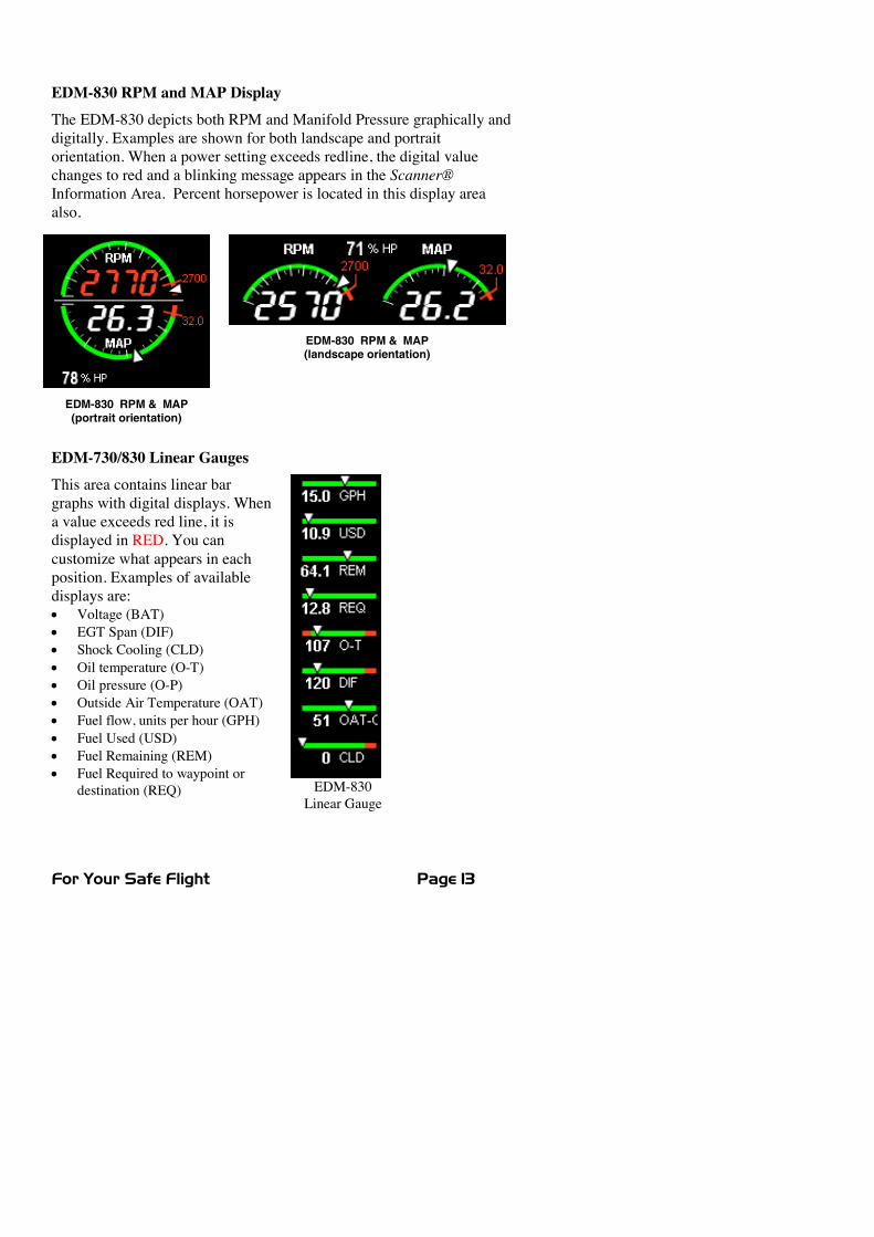
EDM-830 RPM & MAP(portrait orientation)
EDM-830 RPM and MAP DisplayThe EDM-830 depicts both RPM and Manifold Pressure graphically anddigitally. Examples are shown for both landscape and portraitorientation. When a power setting exceeds redline, the digital valuechanges to red and a blinking message appears in the Scanner®Information Area. Percent horsepower is located in this display areaalso.
EDM-730/830 Linear GaugesThis area contains linear bargraphs with digital displays. Whena value exceeds red line, it isdisplayed in RED. You cancustomize what appears in eachposition. Examples of availabledisplays are:x Voltage (BAT)x EGT Span (DIF)x Shock Cooling (CLD)x Oil temperature (O-T)x Oil pressure (O-P)x Outside Air Temperature (OAT)x Fuel flow, units per hour (GPH)x Fuel Used (USD)x Fuel Remaining (REM)x Fuel Required to waypoint or
destination (REQ) EDM-830Linear Gauge
EDM-830 RPM & MAP(landscape orientation)
Page 14 Engine Data Management
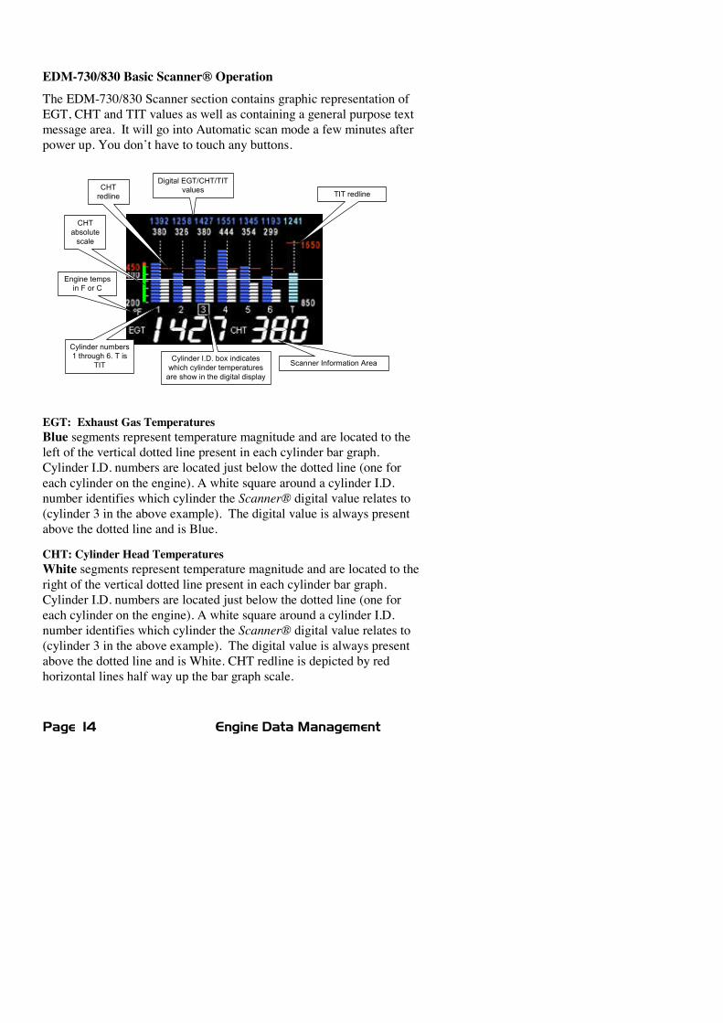
EDM-730/830 Basic Scanner® OperationThe EDM-730/830 Scanner section contains graphic representation ofEGT, CHT and TIT values as well as containing a general purpose textmessage area. It will go into Automatic scan mode a few minutes afterpower up. You don’t have to touch any buttons.
Cylinder numbers1 through 6. T is
TIT
CHTredline
Cylinder I.D. box indicateswhich cylinder temperaturesare show in the digital display
Engine tempsin F or C
TIT redline
Digital EGT/CHT/TITvalues
CHTabsolutescale
Scanner Information Area
EGT: Exhaust Gas TemperaturesBlue segments represent temperature magnitude and are located to theleft of the vertical dotted line present in each cylinder bar graph.Cylinder I.D. numbers are located just below the dotted line (one foreach cylinder on the engine). A white square around a cylinder I.D.number identifies which cylinder the Scanner® digital value relates to(cylinder 3 in the above example). The digital value is always presentabove the dotted line and is Blue.
CHT: Cylinder Head TemperaturesWhite segments represent temperature magnitude and are located to theright of the vertical dotted line present in each cylinder bar graph.Cylinder I.D. numbers are located just below the dotted line (one foreach cylinder on the engine). A white square around a cylinder I.D.number identifies which cylinder the Scanner® digital value relates to(cylinder 3 in the above example). The digital value is always presentabove the dotted line and is White. CHT redline is depicted by redhorizontal lines half way up the bar graph scale.
For Your Safe Flight Page 15
TIT: Turbine Inlet TemperatureLight Blue segments represent temperature magnitude (at the same scaleas EGT) and are located to the right of the last cylinder bar graph set. A‘T’ just below the dotted line identifies this as TIT. When a white squaresurrounds the ‘T’, this signifies that the scanner digital values relate toTIT. The digital value is always present above the dotted line and isLight Blue. TIT redline is depicted by a red horizontal line above themajority of the TIT bar graph area.
There are two views: Normalize view levels the EGT columns andincreases the sensitivity of the Scanner® bar graph columns. To enterthe Normalize view, hold the LeanFind button for three seconds. TheNRM icon will be displayed above the Scanner® section and the barswill be blue. Hold the LeanFind button for three seconds to return to theStandard view. See page 9 for a more detailed description.
Operating ModesThere are three standard operating modes of the EDM: Automatic,Manual, and LeanFind. These modes will be described in more detailbeginning on page 20. When you first turn on the power the EDM startsin the Manual mode, but will enter the Automatic mode after twominutes (most of the time you will operate the EDM in the Automaticmode). The three modes primarily affect the Scanner® InformationArea.
Automatic ModeJust tap the LF button, then tap the STEP button. No userintervention is required to use this mode. Each cylinder and eachparameter value is automatically sequenced and shown in the digitaldisplay for a few seconds.
Manual ModeJust tap the STEP button. This stops Automatic Mode. Each indexedparameter is frozen in the digital display until you manually index to thenext parameter by tapping the STEP button.
LeanFind ModeSimply pre-lean, tap the LF button and begin leaning. The EDM willassist you in finding the correct cylinder to peak to set your mixture to.
Page 16 Engine Data Management
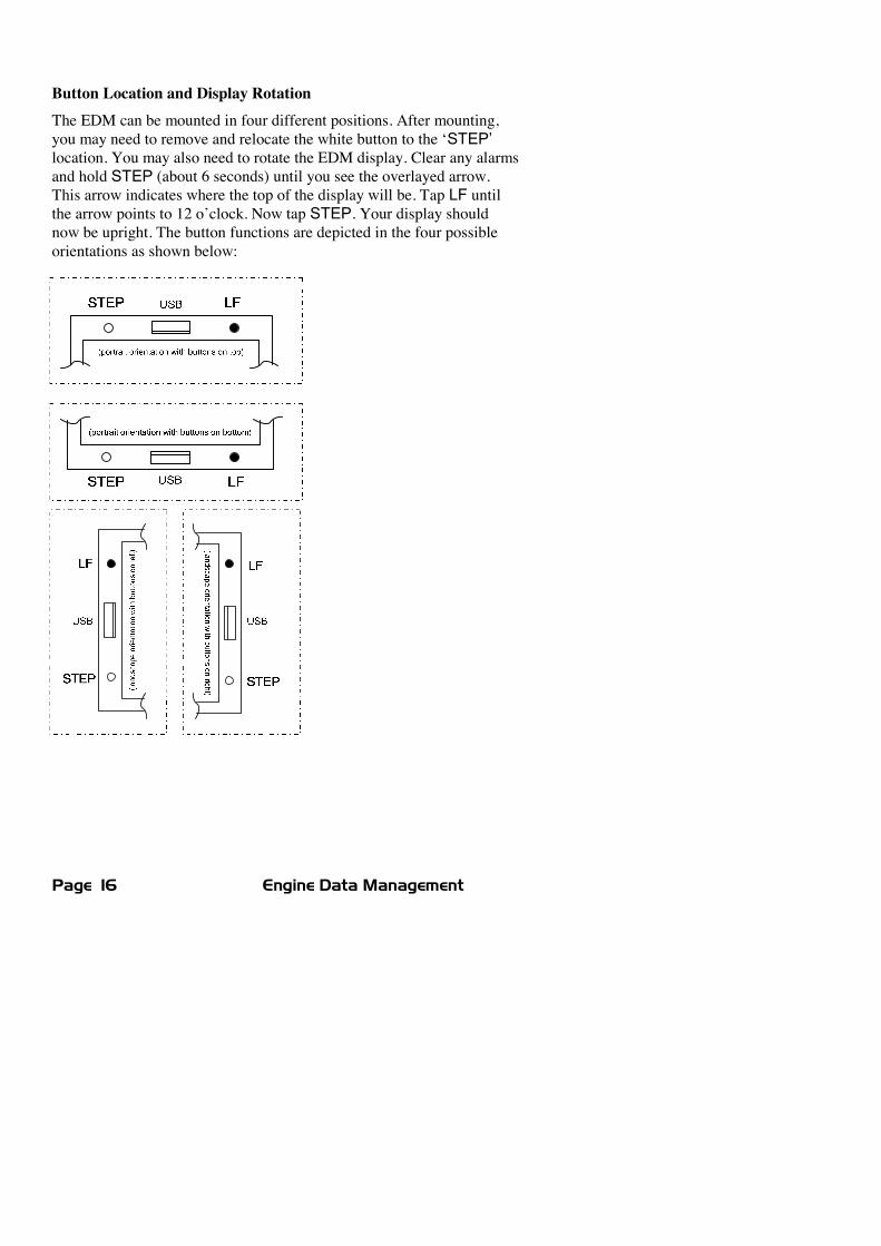
Button Location and Display RotationThe EDM can be mounted in four different positions. After mounting,you may need to remove and relocate the white button to the ‘STEP’location. You may also need to rotate the EDM display. Clear any alarmsand hold STEP (about 6 seconds) until you see the overlayed arrow.This arrow indicates where the top of the display will be. Tap LF untilthe arrow points to 12 o’clock. Now tap STEP. Your display shouldnow be upright. The button functions are depicted in the four possibleorientations as shown below:
For Your Safe Flight Page 17
The STEP and LF buttons control all functions of the EDM. The termtap denotes pressing a button momentarily. The term hold denotespressing and holding a button for five seconds or longer.
STEP Button - Primary functionsx In the Automatic mode, tapping the STEP button will change to
the Manual mode. Subsequent taps of the STEP button willdisplay the next parameters in the sequence.
x In the LeanFind mode tapping the STEP button will terminatethe LeanFind mode and change to the Automatic mode.
STEP Button - Secondary functionsx In the Manual mode, holding the STEP button will display the
previous parameters in the sequence (rapidly backwards).
x In the Pilot Program Mode, tapping the STEP button willgenerally advance to the next item in the list.
x When an alarm is displayed, tapping the STEP button willprevent that alarm from appearing for the next ten minutes.
x When an alarm is displayed, holding the STEP button until theword OFF appears, prevents that alarm from appearing for theremainder of the flight.
LF Button - Primary functionsx In Automatic or Manual modes, tapping the LF button will
change to the LeanFind mode.
x In the LeanFind mode, holding the LF button after peak EGT isfound will display peak EGT.
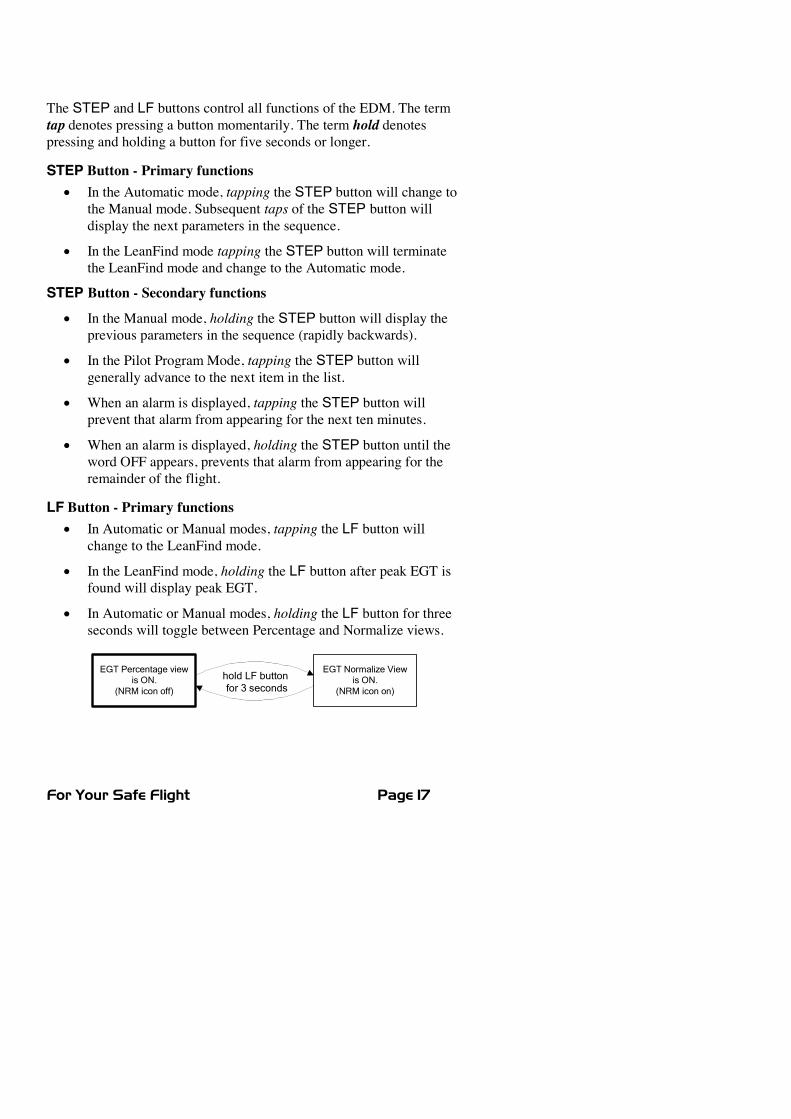
x In Automatic or Manual modes, holding the LF button for threeseconds will toggle between Percentage and Normalize views.
EGT Normalize Viewis ON.
(NRM icon on)
EGT Percentage viewis ON.
(NRM icon off)
hold LF buttonfor 3 seconds
Page 18 Engine Data Management
LF Button - Secondary functionsx In the pilot programming procedure, holding or tapping the LF
button is used to increment or decrement parameter values andtoggle between Yes and No answers to questions.
STEP and LF buttons togetherx Holding both the STEP and LF buttons simultaneously, for
several seconds, changes to the Pilot Programming Mode.
x Holding both the STEP and LF buttons simultaneously forseveral seconds when in a unit programming mode and ‘END? Y’is displayed will take you to the next programming mode (if oneexists).
x Holding both the STEP and LF buttons simultaneously forseveral seconds after entering LeanFind mode but beforebeginning to lean will toggle between leaning ‘Rich Of Peak’ and‘Lean Of Peak’.
x Tapping both the STEP and LF buttons simultaneously inManual mode toggles to include or exclude the displayedparameter from the Automatic mode. It has no affect on thedisplayed parameters in the Manual mode.
For Your Safe Flight Page 19
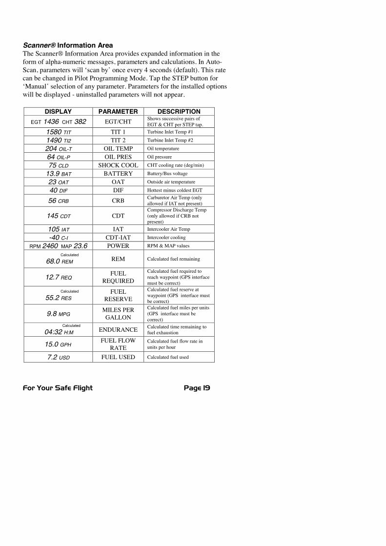
Scanner® Information AreaThe Scanner® Information Area provides expanded information in theform of alpha-numeric messages, parameters and calculations. In Auto-Scan, parameters will ‘scan by’ once every 4 seconds (default). This ratecan be changed in Pilot Programming Mode. Tap the STEP button for‘Manual’ selection of any parameter. Parameters for the installed optionswill be displayed - uninstalled parameters will not appear.
DISPLAY PARAMETER DESCRIPTIONEGT 1436 CHT 382 EGT/CHT Shows successive pairs of
EGT & CHT per STEP tap.1580 TIT TIT 1 Turbine Inlet Temp #1
1490 TI2 TIT 2 Turbine Inlet Temp #2
204 OIL-T OIL TEMP Oil temperature
64 OIL-P OIL PRES Oil pressure
75 CLD SHOCK COOL CHT cooling rate (deg/min)
13.9 BAT BATTERY Battery/Bus voltage
23 OAT OAT Outside air temperature
40 DIF DIF Hottest minus coldest EGT
56 CRB CRB Carburetor Air Temp (onlyallowed if IAT not present)
145 CDT CDTCompressor Discharge Temp(only allowed if CRB notpresent)
105 IAT IAT Intercooler Air Temp
-40 C-I CDT-IAT Intercooler cooling
RPM 2460 MAP 23.6 POWER RPM &MAP values
Calculated
68.0 REM REM Calculated fuel remaining
12.7 REQFUEL
REQUIREDCalculated fuel required toreach waypoint (GPS interfacemust be correct)
Calculated
55.2 RESFUEL
RESERVECalculated fuel reserve atwaypoint (GPS interface mustbe correct)
9.8 MPGMILES PERGALLON
Calculated fuel miles per units(GPS interface must becorrect)
Calculated
04:32 H:M ENDURANCE Calculated time remaining tofuel exhaustion
15.0 GPHFUEL FLOW
RATECalculated fuel flow rate inunits per hour
7.2 USD FUEL USED Calculated fuel used
Page 20 Engine Data Management
Section 2 - Operating Procedures
Built-in Diagnostics: Startup and During FlightWhen your EDM is first turned on, the screen begins by showing theunit model number and TSO category. Next, several display patterns arepresented allowing you to check for proper screen operation. During thistime, the EDM is conducting built-in-tests of certain components,calibration and probes. Any newly installed options are found andlogged in at this time. If a probe problem is found, diagnostic indicationswill be presented on the display. These vary depending on the parameter.For CHT, EGT and TIT, a message appears in the Scanner® InformationArea. For example, if EGT#2 were open circuit, the message would read‘OPEN EGT 2’. For an inoperative horizontal linear gauge function, ared ‘X’ is drawn through it and its digital value is dashed out. Probesdetermined to be faulty during the power up checks are disabled fromthe Scanner® automatic sequence. During flight, probes are periodicallychecked for inconsistent or intermittent signals and are disabled ifdeemed unusable in which case an appropriate message will appear.
EDMModesThe EDM has three different operating modes: Automatic, Manual andLeanFind. When you first turn on the power the EDM starts in theManual mode, but will enter the Automatic mode after a few minutes.The Automatic mode provides you with engine monitoring informationfor the majority of flight conditions. To adjust the mixture, use theLeanFind mode. To display specific parameters, use the Manual mode.In either Automatic or Manual modes, the cylinder bar graphs show agraphic representation of EGT and CHT for each cylinder and TIT (ifpresent).
Automatic ModeJust tap the LF button, then tap the STEP button. No other userintervention is required to use this mode. The EDM will begindisplaying the parameter sequence at the programmed ‘RATE’ (see“Personalizing” on page 45).
For Your Safe Flight Page 21
Individual parameters can be excluded from the Automatic mode: tapSTEP to enter the Manual mode. Tap STEP to select the parameter youwant to exclude. Now tap both STEP and LF buttons simultaneously.Note that tapping the STEP and LF buttons again, toggles back toinclude status.
An excluded parameter displays a decimal point before the parametername.
For example:Included: 14.6 BAT Excluded: 14.6 .BAT
x Every time you turn on the EDM, all parameters are set to‘included’.
x All installed parameters are always displayed in the Manual mode.Exclusion only applies to the Automatic mode.
x All parameters are checked periodically for alarm conditionsregardless of their included or excluded status.
x OIL temperature, EGT, CHT and TIT values cannot be excluded.
Manual ModeJust tap the STEP button. Use the Manual mode when you want tomonitor one specific parameter such as shock cooling during descent, ora particular cylinder temperature during climbs. To change to theManual mode, tap the STEP button once. Subsequent taps will index thedigital display through the parameter sequence (see “Scanner®Information Area” on page 19). To exit the Manual mode and return tothe Automatic mode, tap the LF button and then tap the STEP button.You may disable the Automatic mode by setting scan rate to ‘0’.
‘Excluded’ marker
Page 22 Engine Data Management
LeanFind ModeThe EDM supports two methods of leaning; Rich Of Peak (ROP) andLean Of Peak (LOP). Note: you can set the power-up default to LOP orROP in the Pilot Program Mode but easily change modes during flight.During traditional Rich Of Peak leaning, you’ll finalize the mixture toabout 20 to 80° rich of peak (depending on engine operatingrequirements). However, with the advent of closely balanced injectors(such as GAMI), it is possible to set the mixture lean of peak—thussaving fuel and running the engine cooler. Teledyne Continentalrecommends lean of peak for the Malibu. Both Rich Of Peak and LeanOf Peak processes are described in detail in this manual.
Upon reaching cruise configuration, use the LeanFind mode to identifythe correct cylinder to reach peak EGT (for rich of peak this is theFIRST to peak, for lean of peak this is the LAST to peak). To changefrom one method to the other, just after activating LeanFind, hold STEPand LF and the other method will be momentarily shown: ROP or LOP.Release buttons after other method appears.
The following charts provide step by step guidelines in leaning yourengine, for both rich of peak and lean of peak modes:
For Your Safe Flight Page 23
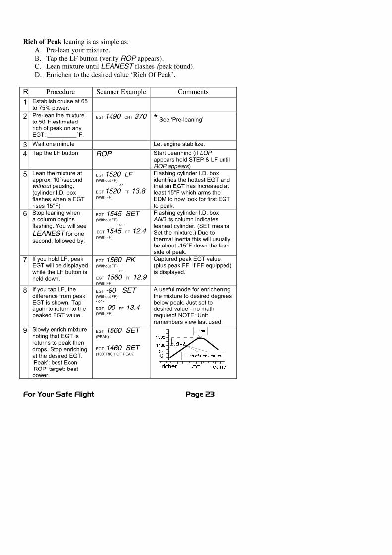
Rich of Peak leaning is as simple as:A. Pre-lean your mixture.B. Tap the LF button (verify ROP appears).C. Lean mixture until LEANEST flashes (peak found).D. Enrichen to the desired value ‘Rich Of Peak’.
R Procedure Scanner Example Comments1 Establish cruise at 65
to 75% power.2 Pre-lean the mixture
to 50°F estimatedrich of peak on anyEGT: _________°F.
EGT1490 CHT 370 * See ‘Pre-leaning’
3 Wait one minute Let engine stabilize.
4 Tap the LF button ROP Start LeanFind (if LOPappears hold STEP & LF untilROP appears)
5 Lean the mixture atapprox. 10°/secondwithout pausing.(cylinder I.D. boxflashes when a EGTrises 15°F)
EGT1520 LF(Without FF)
- or -
EGT1520 FF 13.8(With FF)
Flashing cylinder I.D. boxidentifies the hottest EGT andthat an EGT has increased atleast 15°F which arms theEDM to now look for first EGTto peak.
6 Stop leaning whena column beginsflashing. You will seeLEANEST for onesecond, followed by:
EGT 1545 SET(Without FF)
- or -
EGT1545 FF 12.4(With FF)
Flashing cylinder I.D. boxAND its column indicatesleanest cylinder. (SET meansSet the mixture.) Due tothermal inertia this will usuallybe about -15°F down the leanside of peak.
7 If you hold LF, peakEGT will be displayedwhile the LF button isheld down.
EGT 1560 PK(Without FF)
- or -
EGT 1560 FF 12.9(With FF)
Captured peak EGT value(plus peak FF, if FF equipped)is displayed.
8 If you tap LF, thedifference from peakEGT is shown. Tapagain to return to thepeaked EGT value.
EGT -90 SET(Without FF)- or -
EGT -90 FF 13.4(With FF)
A useful mode for enricheningthe mixture to desired degreesbelow peak. Just set todesired value - no mathrequired! NOTE: Unitremembers view last used.
9 Slowly enrich mixturenoting that EGT isreturns to peak thendrops. Stop enrichingat the desired EGT.‘Peak’: best Econ.‘ROP’ target: bestpower.
EGT 1560 SET(PEAK)
EGT 1460 SET(100º RICH OF PEAK)
Page 24 Engine Data Management
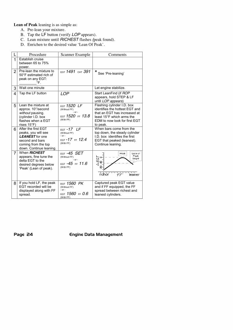
Lean of Peak leaning is as simple as:A. Pre-lean your mixture.B. Tap the LF button (verify LOP appears).C. Lean mixture until RICHEST flashes (peak found).D. Enrichen to the desired value ‘Lean Of Peak’.
L Procedure Scanner Example Comments1 Establish cruise
between 65 to 75%power.
2 Pre-lean the mixture to50°F estimated rich ofpeak on any EGT:_________°F.
EGT1491 CHT 391 * See ‘Pre-leaning’
3 Wait one minute Let engine stabilize.
4 Tap the LF button LOP Start LeanFind (if ROPappears, hold STEP & LFuntil LOP appears)
5 Lean the mixture atapprox. 10°/secondwithout pausing.(cylinder I.D. boxflashes when a EGTrises 15°F)
EGT1520 LF(Without FF)
- or -
EGT1520 FF 13.8(With FF)
Flashing cylinder I.D. boxidentifies the hottest EGT andthat an EGT has increased atleast 15°F which arms theEDM to now look for first EGTto peak.
6 After the first EGTpeaks, you will seeLEANEST for onesecond and barscoming from the topdown. Continue leaning.
EGT -17 LF(Without FF)- or -
EGT -17 FF 12.4(With FF)
When bars come from thetop down, the steady cylinderI.D. box identifies the firstEGT that peaked (leanest).Continue leaning.
7 When RICHESTappears, fine tune thedelta EGT to thedesired degrees below‘Peak’ (Lean of peak).
EGT -45 SET(Without FF)
- or -
EGT -45 FF 11.6(With FF)
8 If you hold LF, the peakEGT recorded will bedisplayed along with FFspread.
EGT 1560 PK(Without FF)- or -
EGT 1560 FF 0.6(With FF)
Captured peak EGT valueand if FF equipped, the FFspread between richest andleanest cylinders.
For Your Safe Flight Page 25
LeanFind Procedure—General Explanation
Lycoming and Continental engines have established specificrestrictions on leaning that must be followed, such aspercentage of power, climb leaning, and TIT limits. Lycomingrecommends operation at peak EGT for power settings of75% or lower, while Continental recommends operation atpeak EGT for power settings of 65% or lower. This guide isnot meant to supersede any specific recommendations of theengine manufacturer or airframe manufacturer.It is your responsibility to know your aircraft’s limitations.
Pre-leaning: The leaning process typically begins with ‘pre-leaning’ toinsure all cylinders are operating rich of peak EGT (note: you canoptionally activate ‘Normalize’ - hold LF until NRM appears - making iteasier to confirm all EGT’s decrease). Now enrichen the mixture toachieve a 50° drop on the hottest EGT. Insure that all EGT’s decrease.Wait one minute to allow temperatures to stabilize.
Lean Find-Initiation: Initiate the EDM leaning mode by tapping the LFbutton. Note that the EDM displays its current leaning modemomentarily: ‘ROP’ for operating Rich of Peak or ‘LOP’ for operatingLean of Peak. To change, simply hold STEP and LF until the displayshows the other mode. The EDM is now waiting for a 15° rise on anyEGT (this feature significantly reduces false peaks). Lean the mixturewithout pausing to achieve about a 10 deg per second change. With avernier mixture control, turn the knob about a quarter turn every second.With a non-vernier or quadrant mixture control, lean slowly andsmoothly about 1/16 inch every five seconds (note: leaning accuratelywith a quadrant system is difficult due to its mechanical linkage).
Lean Find-Activation:When a 15° EGT rise occurs, LeanFind activates(indicated by a cylinder I.D. box flashing over the number of the hottestEGT). Remember: The LeanFind mode is not active until a cylinderI.D. box is flashing. To show the progress of the leaning process, theEDM now displays the hottest EGT in the left side of the digital displayand the word ‘LF’ in the right side (note: with the Fuel Flow optioninstalled, you will see the fuel flow instead of the word ‘LF’). Thisinformation allows you to observe the EGT behavior throughout theleaning process.
Page 26 Engine Data Management
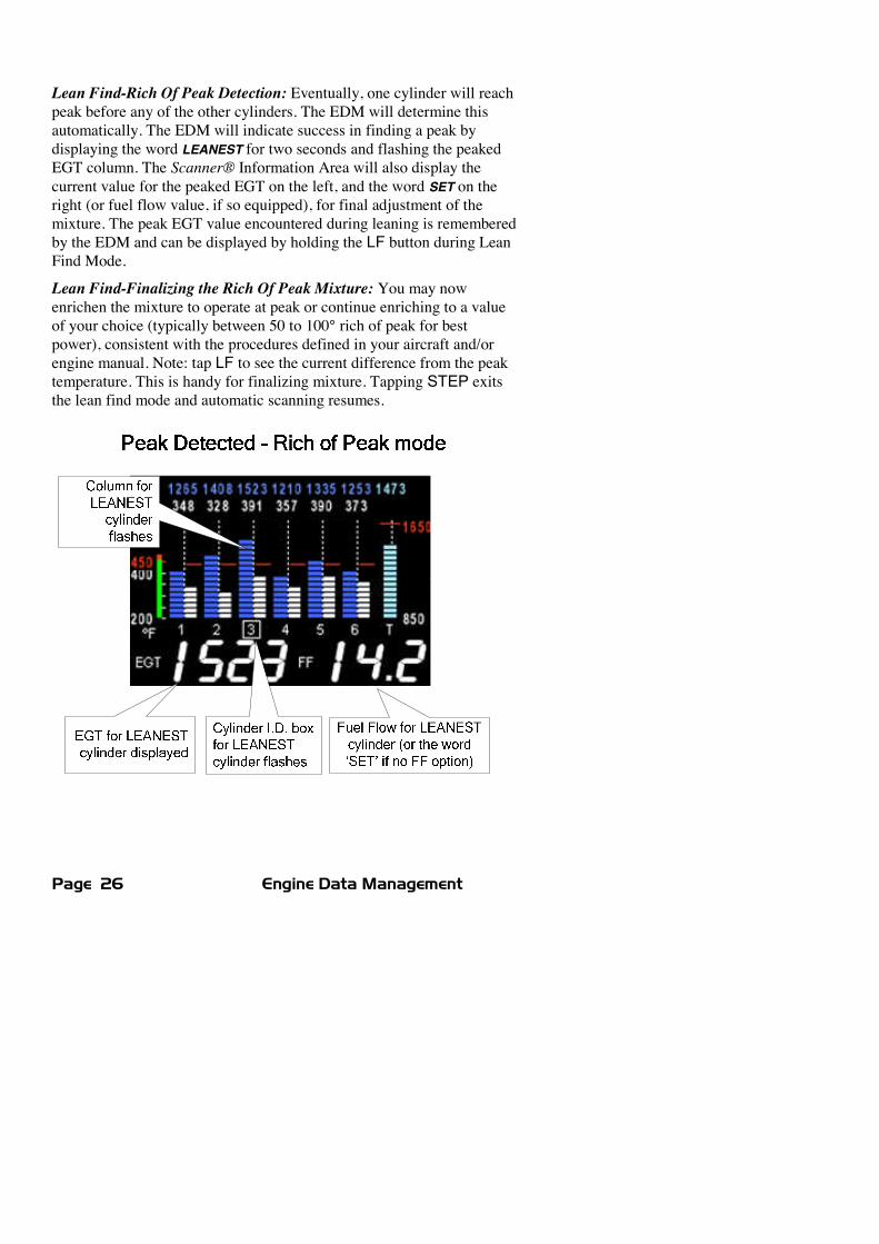
Lean Find-Rich Of Peak Detection: Eventually, one cylinder will reachpeak before any of the other cylinders. The EDM will determine thisautomatically. The EDM will indicate success in finding a peak bydisplaying the word LEANEST for two seconds and flashing the peakedEGT column. The Scanner® Information Area will also display thecurrent value for the peaked EGT on the left, and the word SET on theright (or fuel flow value, if so equipped), for final adjustment of themixture. The peak EGT value encountered during leaning is rememberedby the EDM and can be displayed by holding the LF button during LeanFind Mode.
Lean Find-Finalizing the Rich Of Peak Mixture: You may nowenrichen the mixture to operate at peak or continue enriching to a valueof your choice (typically between 50 to 100° rich of peak for bestpower), consistent with the procedures defined in your aircraft and/orengine manual. Note: tap LF to see the current difference from the peaktemperature. This is handy for finalizing mixture. Tapping STEP exitsthe lean find mode and automatic scanning resumes.

For Your Safe Flight Page 27
Lean Find-Lean Of Peak Detection: Note: This mode should only beused when your engine is equipped with balanced fuel injectors. Whenusing the Lean of Peak mode, you lean until all EGT’s decrease slightlybelow their respective peaks. The EDM has automatic peak detectionand will sequentially indicate leaning progress. When the first EGTpeaks, the word LEANEST appears and the cylinder I.D. box highlightsthe cylinder number. Each column successively drops as leaningcontinues. When the last column drops (last EGT peaks), RICHESTappears and its respective column flashes momentarily. The last EGT topeak is the one you will use when setting the final mixture.
Lean Find-Finalizing the Lean Of Peak Mixture: The Scanner®Information Area displays the degrees below peak for the last (orrichest) EGT to peak, giving you precise information necessary in settingthe final mixture. Adjust the mixture to achieve the desired value belowpeak (using the digital EGT readout) or before engine roughness occurs.Caution: do not lean to the point where the engine runs rough. Note: thepeak EGT value encountered during leaning can be recalled by holdingthe LF button. Tapping STEP exits the lean find mode and automaticscanning resumes.
Page 28 Engine Data Management
Expanded Leaning ProceduresLean Of Peak mode: During the ‘lean of peak’ process, the EDM huntsfor the last cylinder to peak. This is because, ultimately, you want tohave ALL cylinders operating on the lean side of peak. You will finaladjust your mixture to this cylinder. To provide a unique graphicaldepiction during lean of peak operation, the columns become invertedafter the first EGT goes just below peak. Each EGT column thenoriginates from the top of the display and drops downward. As eachsubsequent EGT goes past peak, its column will begin falling. Thecolumns length depicts how far the EGT has dropped below its originalpeak. In this mode, each segment is 5° F. You will continue to lean untilthe last EGT peaks (note: never lean to the point where the engine isrunning rough). When the last EGT peaks, its respective column willflash and the word RICHEST appears. The scanner digital readout willnow show the current temperature difference from where peak EGToccurred and also the current fuel flow (if so equipped). Note: if youhold the LF button, the display will show the captured peak value of the‘last EGT to peak’ and also the difference in fuel flow (if FF equipped)between the first and last to peak (also known as the GAMI Spread).This can be a good indication of how well your injectors are balanced(the smaller the FF difference, the better the injector balance). TappingSTEP exits the lean find mode and automatic scanning resumes.
Leaning Turbocharged Engines: The leaning process for turbochargedengines is by reference to the first EGT or TIT to reach peak. Thereforeyou should use the Rich Of Peak mode. The factory TIT red line may limitthe leaning process, depending on flight conditions. TIT red line is generally1650°F to 1750°F. If TIT exceeds red line (but not by more than 99°), theEDM will allow you to continue leaning for one minute before a TIT alarmactivates, implying you should enrichen the mixture.
NOTE: in some cases, TIT can read approximately 100°F hotter thanthe hottest EGT. This is because of unburned fuel in the exhaustigniting and is not necessarily abnormal behavior. The reduced size ofthe JPI Hastaloy-X-tip probes produce faster response and are moreaccurate than the massive factory installed probes. Therefore a JPI probemay read as much as 100°F higher than the factory installed probe.However, the certified factory-installed gauge must be obeyed as thelimiting factor when adjusting your engine.
For Your Safe Flight Page 29
Operation for each Phase of Flight
Engine Run Up - while RPM is set to run-up value .Suggested setup:Normalize viewManual mode
Verify:x uniform rise of about 50°F in all EGTs in single
magneto operationx uniform rise of EGTs with application of the
mixture control.Be alert for:x unusually low voltage (less than nominal battery
voltage)x cold OILx abnormally high CHTx a higher EGT on one cylinder in dual magneto
operation—indicates fouled spark plug.
NOTE: Include your EDM on your run-up checklist.
Take-Off, Climb, and Full Throttle Operations .Suggested setup:Percentage viewAutomatic mode
Verify:x EGTs and CHTs consistent with past climbs.
EGTs should be the 1100 to 1250°F range (100°to 300°F cooler than cruise) due to fuel cooling.
Be alert for:x high EGT in one cylinder, 300°F above the
others may indicate plugged injector or leakingmanifold gasket.
x If all EGT bars go off scale to the top of thecolumn, be sure you are not in Normalize view.
NOTE: At high density altitude an overly rich mixture can significantlyreduce engine power.
Page 30 Engine Data Management
Cruise - engine stabilized & leaned using LeanFindSuggested setup:Percentage viewAutomatic mode
Be alert for:x uneven EGTs or CHTs (carbureted engines).
Make fine adjustments to throttle, then RPM,then mixture to level the display columns.
x abnormal patterns of EGTs and CHT. (see“Diagnosing Engine Problems” on page 32).
Descent .Suggested setup:Percentage viewManual mode
Be alert for:x CLD: shock cooling alarm default is –60°F.
Average cool rates of –40°F/minute to–60°F/minute are normal, depending on theengine size.
Shock CoolingCooling the cylinders too fast can result in cracking and eventual failure.Lycoming Service Instruction 1094D (March 25, 1994) on Fuel MixtureLeaning Procedures states:
“At all times, caution must be taken not to shock cool thecylinders. The maximum recommended temperature changeshould not exceed 50°F per minute.”
JPI checks shock cooling on all cylinders. The EDM automaticallydisplays the cylinder with the highest rate of cooling.
For Your Safe Flight Page 31
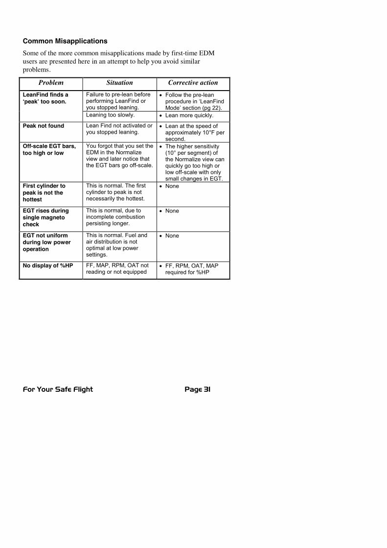
Common MisapplicationsSome of the more common misapplications made by first-time EDMusers are presented here in an attempt to help you avoid similarproblems.
Problem Situation Corrective actionFailure to pre-lean beforeperforming LeanFind oryou stopped leaning.
x Follow the pre-leanprocedure in ‘LeanFindMode’ section (pg 22).
LeanFind finds a‘peak’ too soon.
Leaning too slowly. x Lean more quickly.
Peak not found Lean Find not activated oryou stopped leaning.
x Lean at the speed ofapproximately 10°F persecond.
Off-scale EGT bars,too high or low
You forgot that you set theEDM in the Normalizeview and later notice thatthe EGT bars go off-scale.
x The higher sensitivity(10° per segment) ofthe Normalize view canquickly go too high orlow off-scale with onlysmall changes in EGT.
First cylinder topeak is not thehottest
This is normal. The firstcylinder to peak is notnecessarily the hottest.
x None
EGT rises duringsingle magnetocheck
This is normal, due toincomplete combustionpersisting longer.
x None
EGT not uniformduring low poweroperation
This is normal. Fuel andair distribution is notoptimal at low powersettings.
x None
No display of %HP FF, MAP, RPM, OAT notreading or not equipped
x FF, RPM, OAT, MAPrequired for %HP
Page 32 Engine Data Management
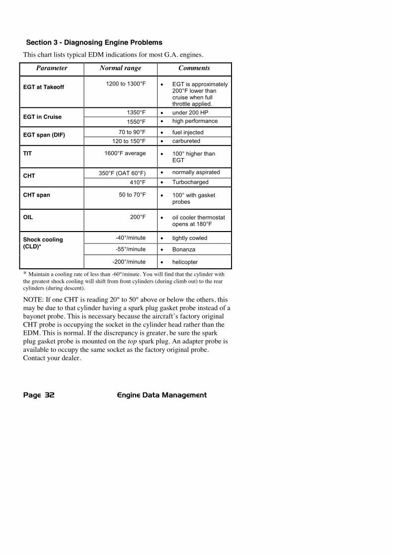
Section 3 - Diagnosing Engine ProblemsThis chart lists typical EDM indications for most G.A. engines.
Parameter Normal range Comments
EGT at Takeoff 1200 to 1300°F x EGT is approximately200°F lower thancruise when fullthrottle applied.
1350°F x under 200 HPEGT in Cruise
1550°F x high performance
70 to 90°F x fuel injectedEGT span (DIF)120 to 150°F x carbureted
TIT 1600°F average x 100° higher thanEGT
350°F (OAT 60°F) x normally aspiratedCHT410°F x Turbocharged
CHT span 50 to 70°F x 100° with gasketprobes
OIL 200°F x oil cooler thermostatopens at 180°F
-40°/minute x tightly cowled
-55°/minute x Bonanza
Shock cooling(CLD)*
-200°/minute x helicopter
* Maintain a cooling rate of less than -60°/minute. You will find that the cylinder withthe greatest shock cooling will shift from front cylinders (during climb out) to the rearcylinders (during descent).
NOTE: If one CHT is reading 20° to 50° above or below the others, thismay be due to that cylinder having a spark plug gasket probe instead of abayonet probe. This is necessary because the aircraft’s factory originalCHT probe is occupying the socket in the cylinder head rather than theEDM. This is normal. If the discrepancy is greater, be sure the sparkplug gasket probe is mounted on the top spark plug. An adapter probe isavailable to occupy the same socket as the factory original probe.Contact your dealer.
For Your Safe Flight Page 33
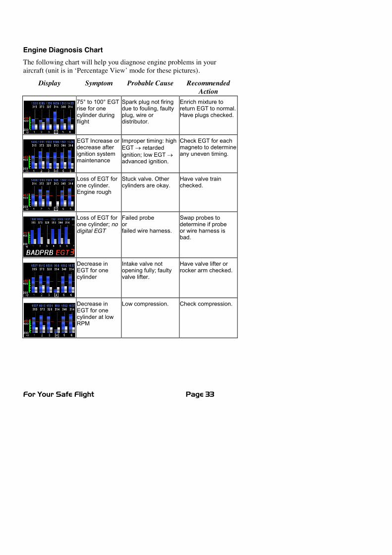
Engine Diagnosis ChartThe following chart will help you diagnose engine problems in youraircraft (unit is in ‘Percentage View’ mode for these pictures).
Display Symptom Probable Cause RecommendedAction
75° to 100° EGTrise for onecylinder duringflight
Spark plug not firingdue to fouling, faultyplug, wire ordistributor.
Enrich mixture toreturn EGT to normal.Have plugs checked.
EGT Increase ordecrease afterignition systemmaintenance
Improper timing: highEGTo retardedignition; low EGToadvanced ignition.
Check EGT for eachmagneto to determineany uneven timing.
Loss of EGT forone cylinder.Engine rough
Stuck valve. Othercylinders are okay.
Have valve trainchecked.
Loss of EGT forone cylinder; nodigital EGT
Failed probeorfailed wire harness.
Swap probes todetermine if probeor wire harness isbad.
Decrease inEGT for onecylinder
Intake valve notopening fully; faultyvalve lifter.
Have valve lifter orrocker arm checked.
Decrease inEGT for onecylinder at lowRPM
Low compression. Check compression.

Page 34 Engine Data Management
Display Symptom Probable Cause RecommendedAction
EGT and CHTnot uniform
Dirty fuel injectors orfouled plugs.
Check injectors andplugs. Non-uniformityis normal forcarbureted engines
Decrease inEGT for allcylinders
Decrease in airflowinto the inductionsystem. Carb orinduction ice.
Engine units set toCelsius
Check for change inmanifold pressure.
Check that the alarmlimits are set toCelsius degrees
Slow rise inEGT. Low CHT
Burned exhaustvalve. CHT is low dueto low power output.
Have compressionchecked.
High CHT oncylinders on oneside of engine
Obstruction undercowling.
Check for improperinstalled baffling, cowlflap misalignment orbird nests.
Rapid rise inEGT/CHT of onecylinder
Detonation. Reduce power.
Sudden off scalerise for any or allcylinders
Pre-ignition,
or Normalize view,
or failed probe.
Full rich and reducepower,
Change toPercentage view,
Check probe.
For Your Safe Flight Page 35
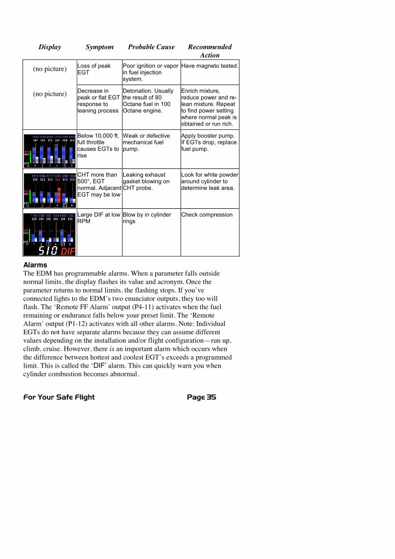
Display Symptom Probable Cause RecommendedAction
(no picture) Loss of peakEGT
Poor ignition or vaporin fuel injectionsystem.
Have magneto tested.
(no picture) Decrease inpeak or flat EGTresponse toleaning process
Detonation. Usuallythe result of 80Octane fuel in 100Octane engine.
Enrich mixture,reduce power and re-lean mixture. Repeatto find power settingwhere normal peak isobtained or run rich.
Below 10,000 ft.full throttlecauses EGTs torise
Weak or defectivemechanical fuelpump.
Apply booster pump.If EGTs drop, replacefuel pump.
CHT more than500°, EGTnormal. AdjacentEGT may be low
Leaking exhaustgasket blowing onCHT probe.
Look for white powderaround cylinder todetermine leak area.
Large DIF at lowRPM
Blow by in cylinderrings
Check compression
AlarmsThe EDM has programmable alarms. When a parameter falls outsidenormal limits, the display flashes its value and acronym. Once theparameter returns to normal limits, the flashing stops. If you’veconnected lights to the EDM’s two enunciator outputs, they too willflash. The ‘Remote FF Alarm’ output (P4-11) activates when the fuelremaining or endurance falls below your preset limit. The ‘RemoteAlarm’ output (P1-12) activates with all other alarms. Note: IndividualEGTs do not have separate alarms because they can assume differentvalues depending on the installation and/or flight configuration—run up,climb, cruise. However, there is an important alarm which occurs whenthe difference between hottest and coolest EGT’s exceeds a programmedlimit. This is called the ‘DIF’ alarm. This can quickly warn you whencylinder combustion becomes abnormal.
Page 36 Engine Data Management
When an alarm is displayed, tapping the STEP button will temporarilydisable the alarm digital indication for the next ten minutes.
When an alarm is displayed, holding the STEP button until the word OFFappears will disable that alarm digital indication for the remainder of theflight. See ‘Factory Limits and GPS’ section on page 52 for a list of thealarms and their factory default settings.
Alarm PriorityIf multiple alarms occur simultaneously, the higher priority alarm willtemporarily “mask” the lower priority alarm(s). When an alarm occurs,note the cause of the alarm and tap the STEP button to clear the alarmindication so that you will be notified of any other alarm that might haveoccurred. The alarm priorities are as follows:
Highest priority CHT High CHTOIL High OIL temperatureTIT High TITOIL Low OIL temperatureCLD Excessive CHT cooling rateDIF Excessive EGT spanBAT High battery voltageBAT Low battery voltageMAP Overboost Manifold pressureO-P Oil pressure
LOREM Low fuel quantity remainingLOH:M Low fuel endurance remaining
Lowest priority FF Low fuel flow
Pre-Ignition and DetonationCombustion that is too rapid leads to detonation and possibly pre-ignition. Detonation is abnormally rapid combustion where the fuel-airmixture explodes instead of burning uniformly. It causes the EGT todecrease and the CHT to increase, and can appear during the leaningprocess. It occurs under high compression from fuel with too low anoctane rating, or from avgas contaminated by jet fuel. Fuel additives,such as lead, boost the octane rating and slow down the combustionprocess, producing an even pressure to the piston.
For Your Safe Flight Page 37
Pre-ignition is caused by hot spots in the cylinder. Ignition occurs priorto the spark plug firing. The EDM depicts pre-ignition as a sudden redline of the EGT on the analog display. This may occur in one or morecylinders. The affected cylinder column(s) will flash while the digitaldisplay will show an EGT higher than 2000°F. At this temperaturepre-ignition will destroy your engine in less than a minute unless youtake immediate corrective action.
Section 4 - Fuel Flow Option Operation
Fuel ManagementWithout a means of measuring accurate fuel flow, you must rely on theaircraft fuel gauges or total time of flight. Aircraft fuel gauges arenotoriously inaccurate (they are only required by the FAA to readaccurately when displaying empty). Determining fuel consumption bymultiplying time of flight by estimated flow rate is, at best, anapproximation, and assumes a constant fuel flow rate for each phase offlight. However, the EDM Fuel Flow Option uses a small, turbinetransducer that measures the fuel flowing into the engine. Higher fuelflow causes the transducer turbine to rotate faster which generates afaster pulse rate. Because the transducer turbine generates thousands ofpulses per gallon of fuel, it can measure with high resolution the amountof fuel that flows into the engine. Prior to engine start you inform theEDM Fuel Flow Option of the known quantity of fuel onboard, itsubsequently tracks all fuel delivered to the engine.
IMPORTANT: For EDM fuel calculations to beaccurate, it is mandatory that you inform the EDM ofthe correct amount of usable fuel onboard the aircraftand confirm proper operation of the fuel flow transducerprior to and during flight. Do not rely on fuel flowinstruments to determine fuel levels in tanks. Refer tooriginal fuel flow instrumentation for primary fuelmanagement information.
Page 38 Engine Data Management
Start Up FuelOn power-up, you will be prompted to enter any fuel you might haveadded to the aircraft (this process updates the REMaining and USEDvalues). The EDM will display FUEL for one second, and then flashFILL? N. If you didn’t add any fuel, simply tap STEP to exit, otherwisetap LF and pick one of the three choices below:
Choice 1) FILL 66 : This shortcut sets REMaining to the MAIN tankvalue (you preset MAIN in Factory Limits setup).
Choice 2) FILL 86 : This shortcut sets REMaining to the sum ofMAINand AUX (you preset AUX in Factory Limits setup).
Choice 3) FILL + : This allows you to adjust your REMaining either upor down by holding or tapping LF. Use when adding apartial amount of fuel.
Once you’ve selected your choice, tap STEP to accept it.
NOTE: If you forgot to update your EDM fuel REMaining before startingthe engine, you can still perform the FILL procedure. The EDM willautomatically subtract any burned fuel from the FILL value you choose (notapplicable to the ‘FILL +’ feature).
The three examples, shown below, depict different aircraft tankconfigurations and how you can update your EDM after refueling youraircraft. These are meant to be general guidelines. You are responsiblefor insuring that your usage of the FILL feature results in the EDMshowing the correct amount of usable fuel REMaining onboard theaircraft.

For Your Safe Flight Page 39
Example A: Aircraft has two fuel tanks with internal tabs.You’ve preset: ‘MAIN = 66’ (33 + 33 usable)
‘AUX = 16’ (8 + 8 usable)When you refuel:‘FILL 66’: use this shortcut when filling to the internal tank tabs.‘FILL 82’: use this shortcut when filling to the caps.(only one tank is shown in each of the two scenarios)
Page 40 Engine Data Management
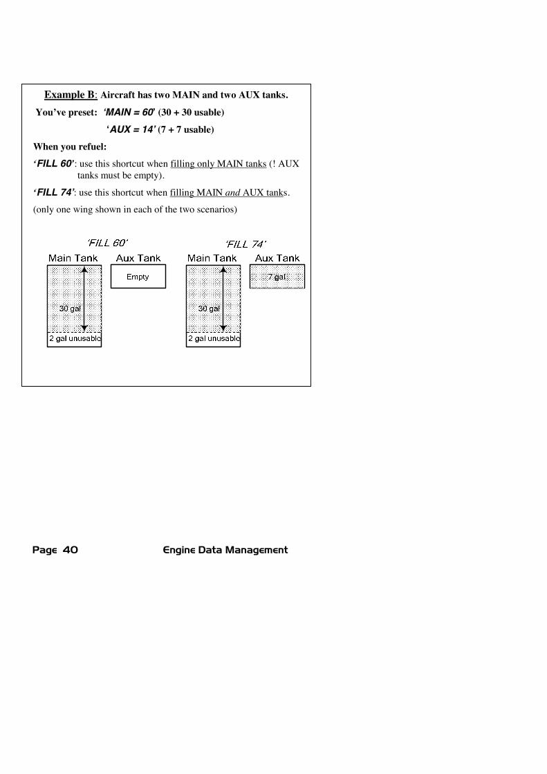
Example B: Aircraft has two MAIN and two AUX tanks.You’ve preset: ‘MAIN = 60’ (30 + 30 usable)
‘AUX = 14’ (7 + 7 usable)When you refuel:‘FILL 60’: use this shortcut when filling only MAIN tanks (! AUX
tanks must be empty).
‘FILL 74’: use this shortcut when filling MAIN and AUX tanks.
(only one wing shown in each of the two scenarios)
For Your Safe Flight Page 41
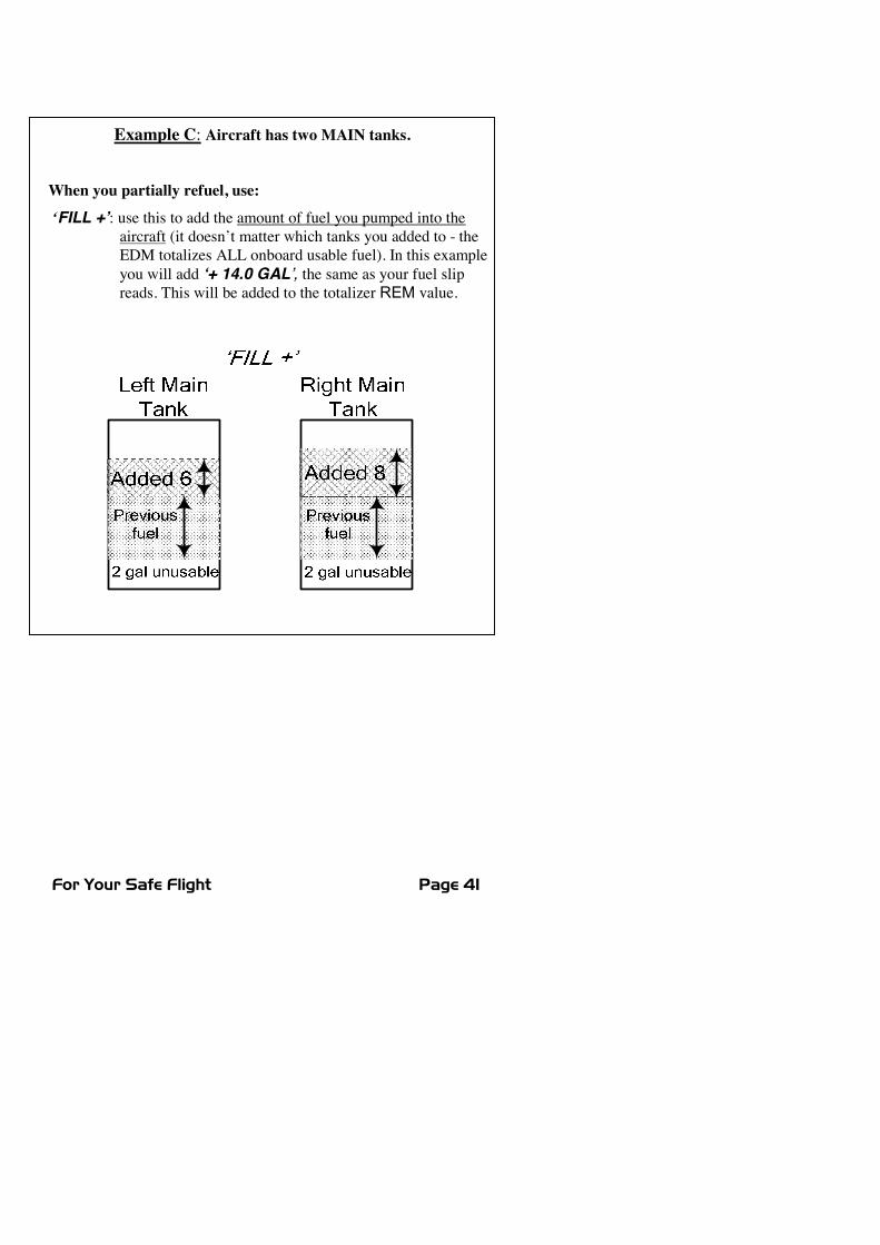
Example C: Aircraft has two MAIN tanks.
When you partially refuel, use:‘FILL +’: use this to add the amount of fuel you pumped into the
aircraft (it doesn’t matter which tanks you added to - theEDM totalizes ALL onboard usable fuel). In this exampleyou will add ‘+ 14.0 GAL’, the same as your fuel slipreads. This will be added to the totalizer REM value.
Page 42 Engine Data Management
Resetting ‘USED’Every time you inform the EDM that the aircraft is refueled, the amountof fuel USED is automatically set to zero (unless the instrument isprogrammed to ACCUM? Y ). To manually zero the amount of fuelUSED at any time, manually STEP to display USED and then holdboth buttons until the display shows ‘0USED’ (this normally takes aboutfive seconds.
Accumulate — Trip TotalizerTo have the USED parameter continuously accumulate total consumedfuel, set ACCUM? Y. This is typically done if you want to track thetotal fuel consumed over a multi-stop cross country. ‘Accumulate’ isdescribed in ‘Pilot Programming’ beginning on page 45. Note: typically,ACCUM? is set to ‘N’ so that USED will be reset every time you fuelthe aircraft.
Fuel Flow Display Select SwitchThe select switch is a three-position toggle switch mounted on yourinstrument panel near the display of the EDM. It selects one of threedifferent sets of parameters to be displayed by the Scanner:
x In the EGT (Temperature) position only the installedtemperature (and battery voltage) parameters are displayed.
x In the ALL (All) position, the EDM both installedtemperature and fuel flow parameters are displayed.
x In the FF (Fuel Flow) position only fuel flow parameters aredisplayed.
Alarm warnings appear regardless of the select switch setting. Alarmsare displayed in the digital display in either Automatic or ManualScanner modes. The select switch does not affect the analog display.
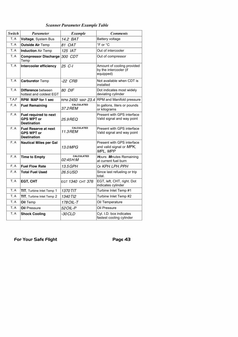
Parameter Scan—Systems with Fuel Flow OptionListed below is the scan sequence, parameter description and an exampleof the digital display. The first column indicates what position the selectswitch must be in to display that particular parameter. T=EGT, F=FFand A= ALL.
For Your Safe Flight Page 43
Scanner Parameter Example Table
Switch Parameter Example CommentsT, A Voltage, System Bus 14.2 BAT Battery voltageT, A Outside Air Temp 81 OAT °F or °CT, A Induction Air Temp 125 IAT Out of intercoolerT, A Compressor Discharge
Temp300 CDT Out of compressor
T, A Intercooler efficiency 25 C-I Amount of cooling providedby the intercooler (ifequipped)
T, A Carburetor Temp -22 CRB Not available when CDT isinstalled
T, A Difference betweenhottest and coldest EGT
80 DIF Dot indicates most widelydeviating cylinder
T,A,F RPM MAP for 1 sec RPM 2450 MAP 23.4 RPM and Manifold pressureF, A Fuel Remaining CALCULATED
37.2REMIn gallons, liters or poundsor kilograms
F, A Fuel required to nextGPS WPT orDestination
25.9REQPresent with GPS interfaceValid signal and way point
F, A Fuel Reserve at nextGPS WPT orDestination
CALCULATED11.3REM
Present with GPS interfaceValid signal and way point
F, A Nautical Miles per Gal13.0MPG
Present with GPS interfaceand valid signal or MPK,MPL, MPP
F, A Time to Empty CALCULATED02:45H:M
Hours: Minutes Remainingat current fuel burn
F, A Fuel Flow Rate 13.5GPH Or KPH, LPH ,PPHF, A Total Fuel Used 26.5USD Since last refueling or trip
total.T, A EGT, CHT EGT 1340 CHT 376 EGT, left, CHT, right. Dot
indicates cylinderT, A TIT, Turbine Inlet Temp 1 1370TIT Turbine Inlet Temp #1T, A TIT, Turbine Inlet Temp 2 1340TI2 Turbine Inlet Temp #2T, A Oil Temp 178OIL-T Oil TemperatureT, A Oil Pressure 52OIL-P Oil PressureT, A Shock Cooling -30CLD Cyl. I.D. box indicates
fastest cooling cylinder
Page 44 Engine Data Management
Section 5 - Long Term Data Memory
The EDM compresses and records all displayed parameters once everysix seconds in Long Term Data Memory (note: you can change this rateto be 2 to 500 seconds). This data is retrievable by inserting a USBDrive into the jack on the front of the instrument and following theprompts. You can choose to retrieve ‘ALL’ the data stored in the EDM,or only the ‘NEW’ data recorded since your last retrieval. In either case,the selected data in the EDM is not erased. The data can later be viewedon EZTrends, a PC program available from JPI or over the internet.
Recording begins when EGTs are greater than 500°F. The amount ofdata that the EDM can store will vary depending on how rapidlyparameters change. The typical storage capacity is greater than 150hours at a 6 second recording interval, but can vary depending on whichoptions are installed. When the memory becomes full, the oldest datawill be discarded to make room for the newest. All data are time-stamped. The EDM contains a real-time clock that may be set when youinitially program your instrument. You may also program an Aircraft IDthat will appear in the output data file. We recommend setting AircraftID to your aircraft registration number or your name. Aircraft ID isinitially factory set to the EDM's serial number. You may change therecording interval from 2 to 500 seconds, even in flight (when youchange the interval in flight, the current flight file is closed and a newflight file is started at the new interval). During built-in tests, the EDMdisplays the Model, Date, Time, Percent Memory filled (since the lastdownload), and the Aircraft ID.
Downloading from Long Term MemoryFrom either Automatic Scanner or Manual Scanner mode, simply plug aproperly formatted USB Drive into the front panel jack (note: you mustclear any alarms that are present for downloading to commence).
There are three download choices:‘DUMP NEW’ : download all NEW flights since last download.‘DUMP ALL’ : download ALL flights in the EDM memory.‘DUMP EXIT’ : EXIT the download mode.
Tap the LF button to select a choice, then Tap STEP button to execute.
CAUTION: Do not insert anything but a USB Flash Drive Stickin the USB Port!
For Your Safe Flight Page 45
The EDM will show messages and percent complete indicators to keepyou apprised of progress. When the download is complete the EDM maybriefly show DONE. Wait a few seconds for the display to return to thenormal engine monitoring mode and then remove your USB Drive. Thiscompletes the download.
Transferring from the USB Flash Drive to a PCTo transfer your data from the USB flash drive to your PC, follow theseeasy steps.
1. On your PC, start the EzTrends program.2. Plug in the USB flash drive into an available USB port.3. In EzTrends, select the Move and Plot Data from Memory Stickoption.
4. In the displayed list, find the USB flash drive and double click it.5. Select the file you wish to plot and then select the flight in that file.
Refer to the EzTrends manual for details on how to use EzTrends.
Section 6 - Personalizing
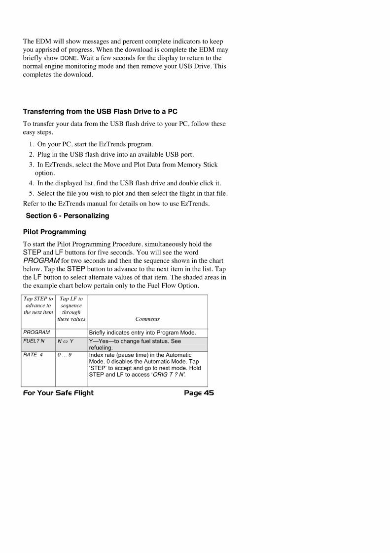
Pilot ProgrammingTo start the Pilot Programming Procedure, simultaneously hold theSTEP and LF buttons for five seconds. You will see the wordPROGRAM for two seconds and then the sequence shown in the chartbelow. Tap the STEP button to advance to the next item in the list. Tapthe LF button to select alternate values of that item. The shaded areas inthe example chart below pertain only to the Fuel Flow Option.
Tap STEP toadvance tothe next item
Tap LF tosequencethrough
these values Comments
PROGRAM Briefly indicates entry into Program Mode.FUEL? N N� Y Y—Yes—to change fuel status. See
refueling.RATE 4 0 … 9 Index rate (pause time) in the Automatic
Mode. 0 disables the Automatic Mode. Tap‘STEP’ to accept and go to next mode. HoldSTEP and LF to access ‘ORIG T ? N’.
Page 46 Engine Data Management
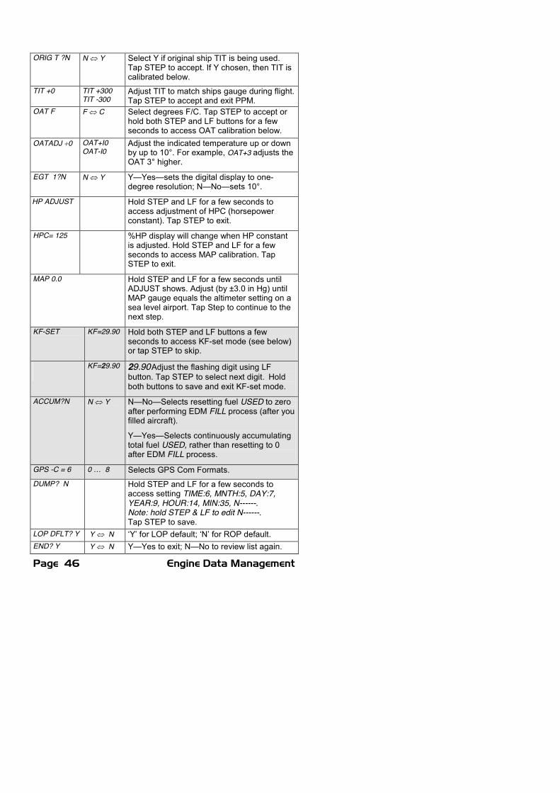
ORIG T ?N N� Y Select Y if original ship TIT is being used.Tap STEP to accept. If Y chosen, then TIT iscalibrated below.
TIT +0 TIT +300TIT -300
Adjust TIT to match ships gauge during flight.Tap STEP to accept and exit PPM.
OAT F F� C Select degrees F/C. Tap STEP to accept orhold both STEP and LF buttons for a fewseconds to access OAT calibration below.
OATADJ �0 OAT+I0OAT-I0
Adjust the indicated temperature up or downby up to 10°. For example, OAT+3 adjusts theOAT 3° higher.
EGT 1?N N� Y Y—Yes—sets the digital display to one-degree resolution; N—No—sets 10°.
HP ADJUST Hold STEP and LF for a few seconds toaccess adjustment of HPC (horsepowerconstant). Tap STEP to exit.
HPC= 125 %HP display will change when HP constantis adjusted. Hold STEP and LF for a fewseconds to access MAP calibration. TapSTEP to exit.
MAP 0.0 Hold STEP and LF for a few seconds untilADJUST shows. Adjust (by ±3.0 in Hg) untilMAP gauge equals the altimeter setting on asea level airport. Tap Step to continue to thenext step.
KF-SET KF=29.90 Hold both STEP and LF buttons a fewseconds to access KF-set mode (see below)or tap STEP to skip.
KF=29.90 29.90Adjust the flashing digit using LFbutton. Tap STEP to select next digit. Holdboth buttons to save and exit KF-set mode.
ACCUM?N N� Y N—No—Selects resetting fuel USED to zeroafter performing EDM FILL process (after youfilled aircraft).
Y—Yes—Selects continuously accumulatingtotal fuel USED, rather than resetting to 0after EDM FILL process.
GPS -C = 6 0 … 8 Selects GPS Com Formats.DUMP? N Hold STEP and LF for a few seconds to
access setting TIME:6, MNTH:5, DAY:7,YEAR:9, HOUR:14, MIN:35, N------.Note: hold STEP & LF to edit N------.Tap STEP to save.
LOP DFLT? Y Y � N ‘Y’ for LOP default; ‘N’ for ROP default.END? Y Y � N Y—Yes to exit; N—No to review list again.

For Your Safe Flight Page 47
Section 7 - Programming Horsepower ConstantFor EDM’s equipped with FF, RPM, OAT and MAP, you will adjust theHP Constant once for your aircraft (NOTE: perform MAPadjustment prior to this process) Follow the steps below:1. Prior to takeoff, with the engine running, enter Pilot Program Mode
(hold STEP and LF until ‘PROGRAM’ is displayed).2. Tap STEP until you see HP ADJUST. Hold both STEP and LF
until you see HPC=108 (your value may be different). Try changingthe constant by tapping/holding the LF button. Note that the %HPgauge value changes as you change the constant. This adjustmentwill be performed while airborne.
3. Once airborne, by reference to the Aircraft Flight Manual (AFM),not the EDM , setup a constant power setting of 70% in straight andlevel flight below 10,000 feet (be sure your mixture is Rich of Peak).If necessary, re-enter the HP constant mode (steps 1 & 2 above).Adjust the HP constant until the EDM’s %HP is as close as possibleto 70%. Note: the reading is the percent of maximum HP, notactual HP.
4. Tap the STEP button to save and exit.
Section 8 - Programming Manifold Pressure (MAP)Do this one time and only if the MAP on your manifold pressuregauge doesn't match the MAP shown on the EDM.1. Do this on the ground with the engine turned off.2. Enter the pilot program mode by simultaneously holding the STEP
and LF buttons for a few seconds.
3. Tap STEP to index to HP ADJUST.4. Hold both the STEP and LF buttons and you will see HPC=108
(note: your value may differ from ‘108’).
5. Hold both the STEP and LF buttons and you will see MAP 0.0 .6. You will need to determine and set the absolute air pressure (this is
what MAP displays). Depending on your airport elevation, use eithermethod ‘A’ or ‘B’ below:
A. Airport at sea level: adjust the MAP gauge digital display to theairport ATIS altimeter setting (or to your altimeter Kollsman
Page 48 Engine Data Management
window if no ATIS available) by tapping/holding the LF button.The range is +/- 3 in HG.
OR
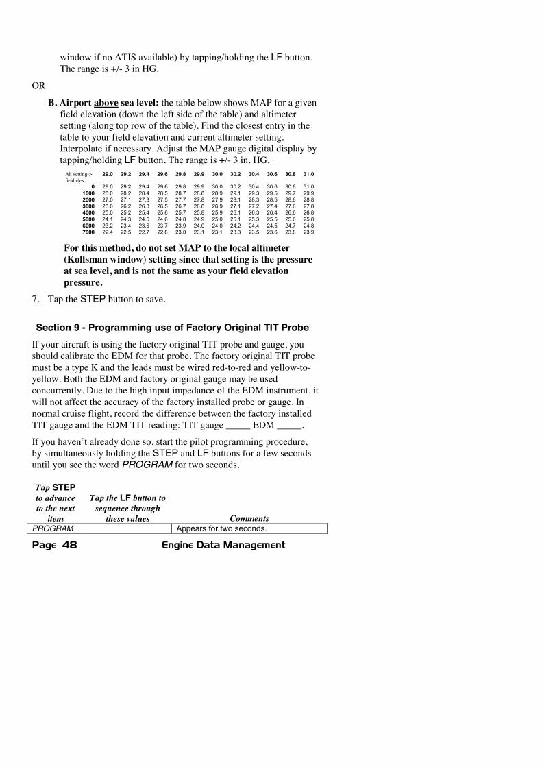
B. Airport above sea level: the table below shows MAP for a givenfield elevation (down the left side of the table) and altimetersetting (along top row of the table). Find the closest entry in thetable to your field elevation and current altimeter setting.Interpolate if necessary. Adjust the MAP gauge digital display bytapping/holding LF button. The range is +/- 3 in. HG.Alt setting->field elev.
29.0 29.2 29.4 29.6 29.8 29.9 30.0 30.2 30.4 30.6 30.8 31.0
0 29.0 29.2 29.4 29.6 29.8 29.9 30.0 30.2 30.4 30.6 30.8 31.01000 28.0 28.2 28.4 28.5 28.7 28.8 28.9 29.1 29.3 29.5 29.7 29.92000 27.0 27.1 27.3 27.5 27.7 27.8 27.9 28.1 28.3 28.5 28.6 28.83000 26.0 26.2 26.3 26.5 26.7 26.8 26.9 27.1 27.2 27.4 27.6 27.84000 25.0 25.2 25.4 25.6 25.7 25.8 25.9 26.1 26.3 26.4 26.6 26.85000 24.1 24.3 24.5 24.6 24.8 24.9 25.0 25.1 25.3 25.5 25.6 25.86000 23.2 23.4 23.6 23.7 23.9 24.0 24.0 24.2 24.4 24.5 24.7 24.87000 22.4 22.5 22.7 22.8 23.0 23.1 23.1 23.3 23.5 23.6 23.8 23.9
For this method, do not set MAP to the local altimeter(Kollsman window) setting since that setting is the pressureat sea level, and is not the same as your field elevationpressure.
7. Tap the STEP button to save.
Section 9 - Programming use of Factory Original TIT ProbeIf your aircraft is using the factory original TIT probe and gauge, youshould calibrate the EDM for that probe. The factory original TIT probemust be a type K and the leads must be wired red-to-red and yellow-to-yellow. Both the EDM and factory original gauge may be usedconcurrently. Due to the high input impedance of the EDM instrument, itwill not affect the accuracy of the factory installed probe or gauge. Innormal cruise flight, record the difference between the factory installedTIT gauge and the EDM TIT reading: TIT gauge _____ EDM _____.
If you haven’t already done so, start the pilot programming procedure,by simultaneously holding the STEP and LF buttons for a few secondsuntil you see the word PROGRAM for two seconds.
Tap STEPto advanceto the nextitem
Tap the LF button tosequence throughthese values Comments
PROGRAM Appears for two seconds.
For Your Safe Flight Page 49
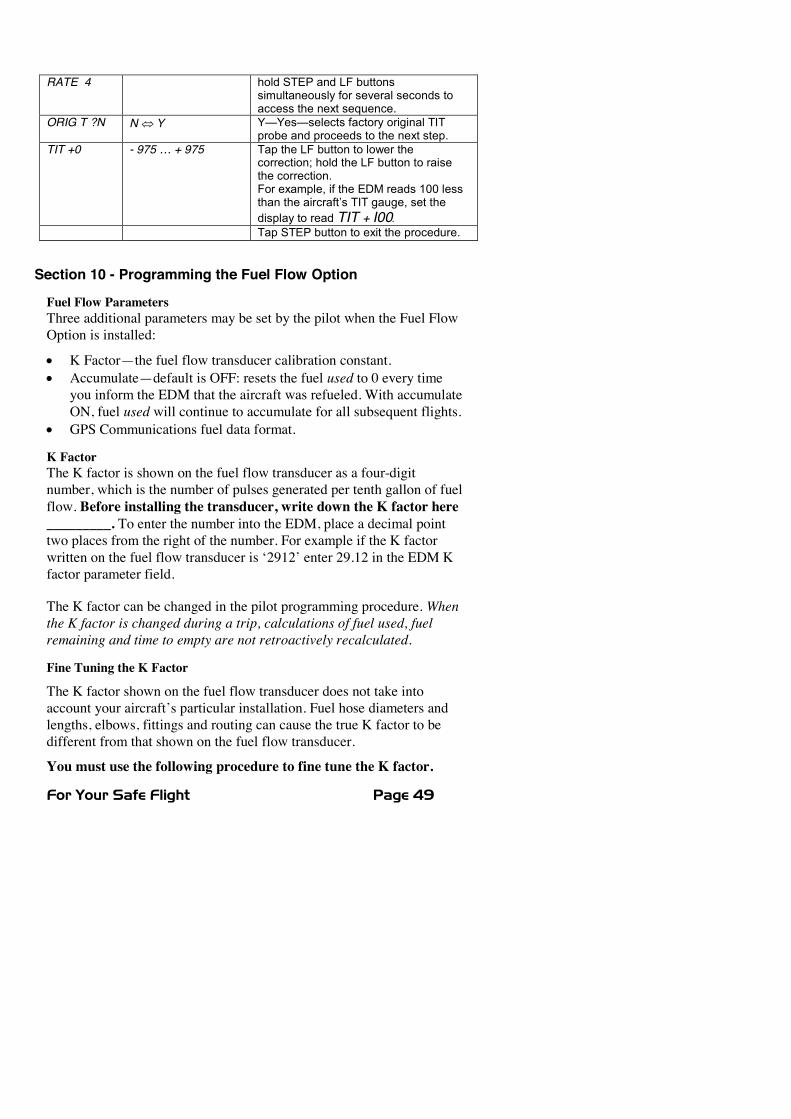
RATE 4 hold STEP and LF buttonssimultaneously for several seconds toaccess the next sequence.
ORIG T ?N N� Y Y—Yes—selects factory original TITprobe and proceeds to the next step.
TIT +0 - 975 … + 975 Tap the LF button to lower thecorrection; hold the LF button to raisethe correction.For example, if the EDM reads 100 lessthan the aircraft’s TIT gauge, set thedisplay to read TIT + I00.Tap STEP button to exit the procedure.
Section 10 - Programming the Fuel Flow Option
Fuel Flow ParametersThree additional parameters may be set by the pilot when the Fuel FlowOption is installed:
x K Factor—the fuel flow transducer calibration constant.x Accumulate—default is OFF: resets the fuel used to 0 every time
you inform the EDM that the aircraft was refueled. With accumulateON, fuel used will continue to accumulate for all subsequent flights.
x GPS Communications fuel data format.
K FactorThe K factor is shown on the fuel flow transducer as a four-digitnumber, which is the number of pulses generated per tenth gallon of fuelflow. Before installing the transducer, write down the K factor here_________. To enter the number into the EDM, place a decimal pointtwo places from the right of the number. For example if the K factorwritten on the fuel flow transducer is ‘2912’ enter 29.12 in the EDM Kfactor parameter field.
The K factor can be changed in the pilot programming procedure. Whenthe K factor is changed during a trip, calculations of fuel used, fuelremaining and time to empty are not retroactively recalculated.
Fine Tuning the K Factor
The K factor shown on the fuel flow transducer does not take intoaccount your aircraft’s particular installation. Fuel hose diameters andlengths, elbows, fittings and routing can cause the true K factor to bedifferent from that shown on the fuel flow transducer.
You must use the following procedure to fine tune the K factor.
Page 50 Engine Data Management
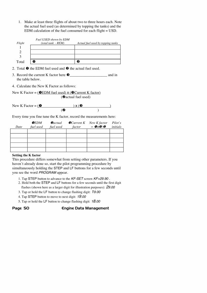
1. Make at least three flights of about two to three hours each. Notethe actual fuel used (as determined by topping the tanks) and theEDM calculation of the fuel consumed for each flight = USD.
FlightFuel USED shown by EDM
(total tank - REM) Actual fuel used by topping tanks123
Total n o
2. Totaln the EDM fuel used ando the actual fuel used.
3. Record the current K factor herep____________________ and inthe table below.
4. Calculate the New K Factor as follows:
New K Factor = (nEDM fuel used) x (pCurrent K factor)(oactual fuel used)
New K Factor = (n ) x (p )(o )
Every time you fine tune the K factor, record the measurements here:
DatenEDMfuel used
oactualfuel used
pCurrent Kfactor
New K factor=nxp/o
Pilot’sinitials
Setting the K factorThis procedure differs somewhat from setting other parameters. If youhaven’t already done so, start the pilot programming procedure bysimultaneously holding the STEP and LF buttons for a few seconds untilyou see the word PROGRAM appear.
1. Tap STEP button to advance to the KF-SET screen KF=29.90 .2. Hold both the STEP and LF buttons for a few seconds until the first digitflashes (shown here as a larger digit for illustration purposes): 29.00
3. Tap or hold the LF button to change flashing digit: 19.004. Tap STEP button to move to next digit: 19.005. Tap or hold the LF button to change flashing digit: 18.00
For Your Safe Flight Page 51
6. Tap STEP button for next digit: 18.007. Repeat items 5 and 6 for the remaining two digits.8. Hold STEP and LF buttons until the parameter is saved.
Accumulate Total—Trip TotalSelect this from the Pilot Program Mode. Select ‘N’ if you wish todisplay total fuel used since the last time you informed the EDM that theaircraft was refueled. Select ‘Y’ to display total fuel used for an extendedtrip with multiple fuel stops. This selection affects only the USDparameter.
GPS-C Comm settingsSelect this from the Pilot Program Mode. The GPS-C setting selects theformat of the fuel data output of the EDM. See page 57.
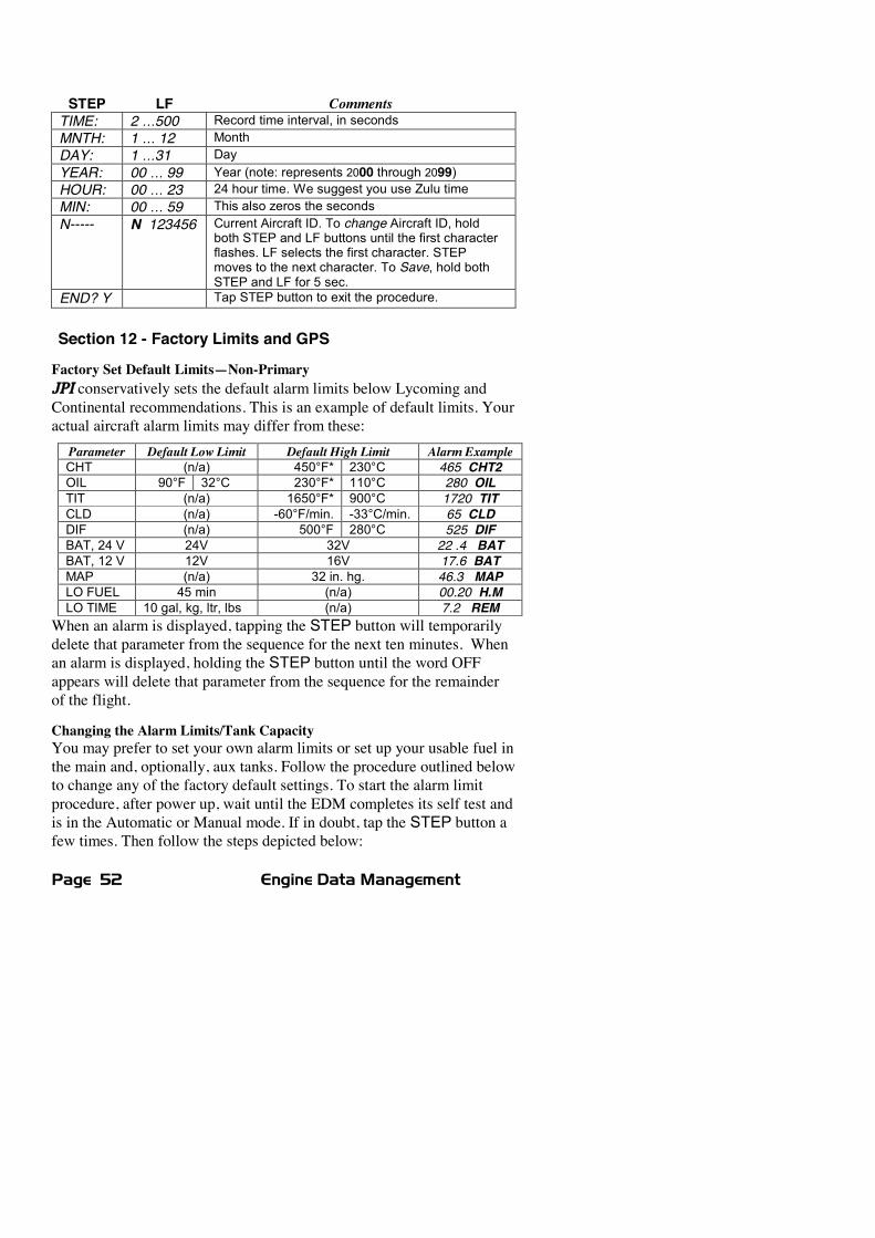
Section 11 - Programming Long Term Data MemoryIf you haven’t already done so, start the Pilot Programming Mode byholding the STEP and LF buttons for a few seconds until the wordPROGRAM appears for two seconds. To change the date, time and userid for the Long Term Data Memory, tap the STEP button until thedisplay shows DUMP? N. Next, hold STEP and LF buttons for fiveseconds until ‘TIME: 6’ appears. Then set the data memory parameters asshow below:
Page 52 Engine Data Management
STEP LF CommentsTIME: 2 …500 Record time interval, in secondsMNTH: 1 … 12 MonthDAY: 1 …31 DayYEAR: 00 … 99 Year (note: represents 2000 through 2099)HOUR: 00 … 23 24 hour time. We suggest you use Zulu timeMIN: 00 … 59 This also zeros the secondsN----- N 123456 Current Aircraft ID. To change Aircraft ID, hold
both STEP and LF buttons until the first characterflashes. LF selects the first character. STEPmoves to the next character. To Save, hold bothSTEP and LF for 5 sec.
END? Y Tap STEP button to exit the procedure.
Section 12 - Factory Limits and GPS
Factory Set Default Limits—Non-PrimaryJPI conservatively sets the default alarm limits below Lycoming andContinental recommendations. This is an example of default limits. Youractual aircraft alarm limits may differ from these:Parameter Default Low Limit Default High Limit Alarm ExampleCHT (n/a) 450°F* 230°C 465 CHT2OIL 90°F 32°C 230°F* 110°C 280 OILTIT (n/a) 1650°F* 900°C 1720 TITCLD (n/a) -60°F/min. -33°C/min. 65 CLDDIF (n/a) 500°F 280°C 525 DIFBAT, 24 V 24V 32V 22 .4 BATBAT, 12 V 12V 16V 17.6 BATMAP (n/a) 32 in. hg. 46.3 MAPLO FUEL 45 min (n/a) 00.20 H.MLO TIME 10 gal, kg, ltr, lbs (n/a) 7.2 REM
When an alarm is displayed, tapping the STEP button will temporarilydelete that parameter from the sequence for the next ten minutes. Whenan alarm is displayed, holding the STEP button until the word OFFappears will delete that parameter from the sequence for the remainderof the flight.
Changing the Alarm Limits/Tank CapacityYou may prefer to set your own alarm limits or set up your usable fuel inthe main and, optionally, aux tanks. Follow the procedure outlined belowto change any of the factory default settings. To start the alarm limitprocedure, after power up, wait until the EDM completes its self test andis in the Automatic or Manual mode. If in doubt, tap the STEP button afew times. Then follow the steps depicted below:
For Your Safe Flight Page 53
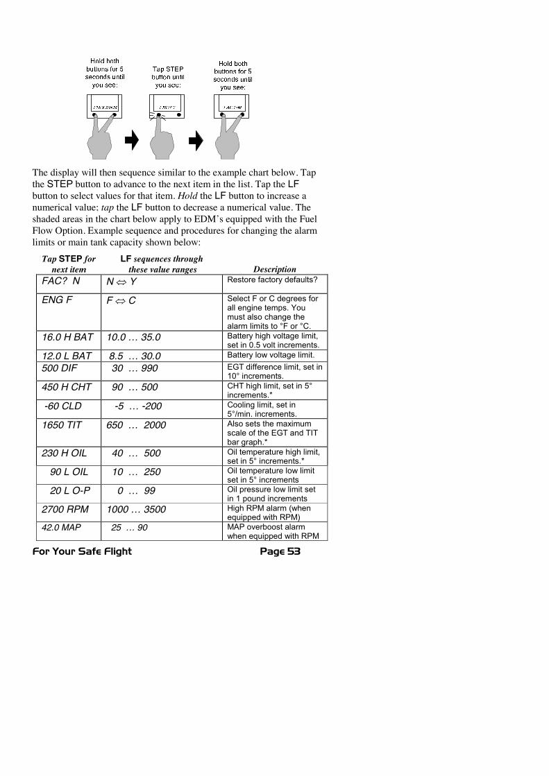
The display will then sequence similar to the example chart below. Tapthe STEP button to advance to the next item in the list. Tap the LFbutton to select values for that item. Hold the LF button to increase anumerical value; tap the LF button to decrease a numerical value. Theshaded areas in the chart below apply to EDM’s equipped with the FuelFlow Option. Example sequence and procedures for changing the alarmlimits or main tank capacity shown below:Tap STEP fornext item
LF sequences throughthese value ranges Description
FAC? N N� Y Restore factory defaults?
ENG F F� C Select F or C degrees forall engine temps. Youmust also change thealarm limits to °F or °C.
16.0 H BAT 10.0 … 35.0 Battery high voltage limit,set in 0.5 volt increments.
12.0 L BAT 8.5 … 30.0 Battery low voltage limit.
500 DIF 30 … 990 EGT difference limit, set in10° increments.
450 H CHT 90 … 500 CHT high limit, set in 5°increments.*
-60 CLD -5 … -200 Cooling limit, set in5°/min. increments.
1650 TIT 650 … 2000 Also sets the maximumscale of the EGT and TITbar graph.*
230 H OIL 40 … 500 Oil temperature high limit,set in 5° increments.*
90 L OIL 10 … 250 Oil temperature low limitset in 5° increments
20 L O-P 0 … 99 Oil pressure low limit setin 1 pound increments
2700 RPM 1000 … 3500 High RPM alarm (whenequipped with RPM)
42.0 MAP 25 … 90 MAP overboost alarmwhen equipped with RPM
Page 54 Engine Data Management
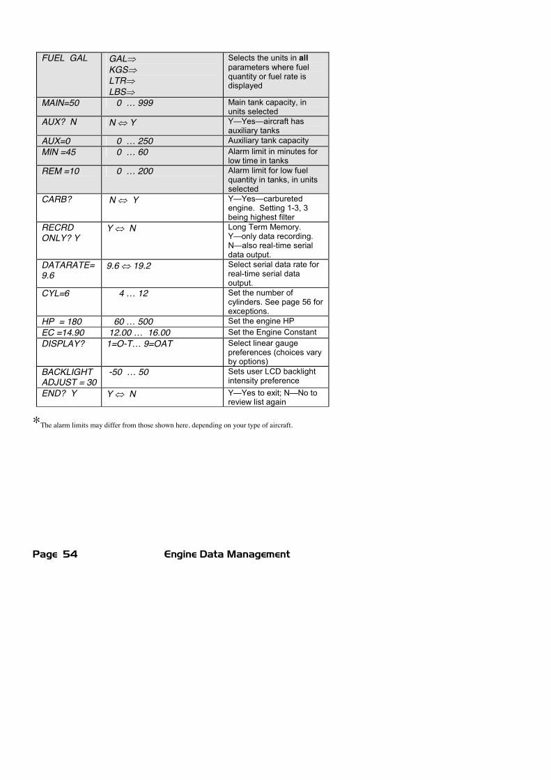
FUEL GAL GAL�KGS�LTR�LBS�
Selects the units in allparameters where fuelquantity or fuel rate isdisplayed
MAIN=50 0 … 999 Main tank capacity, inunits selected
AUX? N N� Y Y—Yes—aircraft hasauxiliary tanks
AUX=0 0 … 250 Auxiliary tank capacityMIN =45 0 … 60 Alarm limit in minutes for
low time in tanksREM =10 0 … 200 Alarm limit for low fuel
quantity in tanks, in unitsselected
CARB? N� Y Y—Yes—carburetedengine. Setting 1-3, 3being highest filter
RECRDONLY? Y
Y� N Long Term Memory.Y—only data recording.N—also real-time serialdata output.
DATARATE=9.6
9.6� 19.2 Select serial data rate forreal-time serial dataoutput.
CYL=6 4 … 12 Set the number ofcylinders. See page 56 forexceptions.
HP = 180 60 … 500 Set the engine HPEC =14.90 12.00 … 16.00 Set the Engine ConstantDISPLAY? 1=O-T… 9=OAT Select linear gauge
preferences (choices varyby options)
BACKLIGHTADJUST = 30
-50 … 50 Sets user LCD backlightintensity preference
END? Y Y� N Y—Yes to exit; N—No toreview list again
*The alarm limits may differ from those shown here, depending on your type of aircraft.
For Your Safe Flight Page 55
MAP, Fuel Flow Alarm Limits, Units, Fuel Capacity
MAP Overboost AlarmEnter the redline for overboost on turbocharged engines.
Fuel Flow Units (shaded area above)Selects the units in all measurements where fuel quantity or fuel rate isdisplayed. If you change this parameter, it does not change thenumerical value of the fuel tank capacity. You must do thismanually. For example if you change from Gal. to Lbs., the tankcapacity will be interpreted as 50 Lbs. rather than 50 gallons; the EDMwill not automatically convert 50 Gal to equivalent pounds.
Main Tank CapacityEnter the total usable fuel capacity of the main tanks in the fuel flowunits selected.
If you do not have auxiliary tanks or tank tabs, answer “No.” If youanswer “Yes,” you will be asked to input the capacity of the auxiliarytanks in the fuel flow units selected. Another scenario is if you have tanktabs and sometimes fill only to the tabs. In this case you may set theauxiliary tank capacity to the difference between full tank capacity andtab capacity. Note: The EDM does not differentiate fuel flow betweenthe main and auxiliary tanks; it tracks only total usable fuel in theaircraft.
Low Time Alarm LimitSelect the value of the time remaining, in minutes, that triggers thealarm. Time remaining is determined by dividing the current calculatedfuel remaining by the current fuel flow rate.Low Fuel Alarm LimitSelect the value of the fuel remaining, in the selected fuel flow units,that triggers the alarm. Fuel remaining is a calculated value and isdependent on what you’ve programmed into the EDM when refuelingand the performance of the fuel flow transducer.
Carburetor?Different response filters are used depending on whether your engine iscarbureted or fuel injected. The filter for a carbureted engine has aslower response time to reduce sudden fluctuations in readings. Thehigher the number, the more filtering (the reading is smoother).
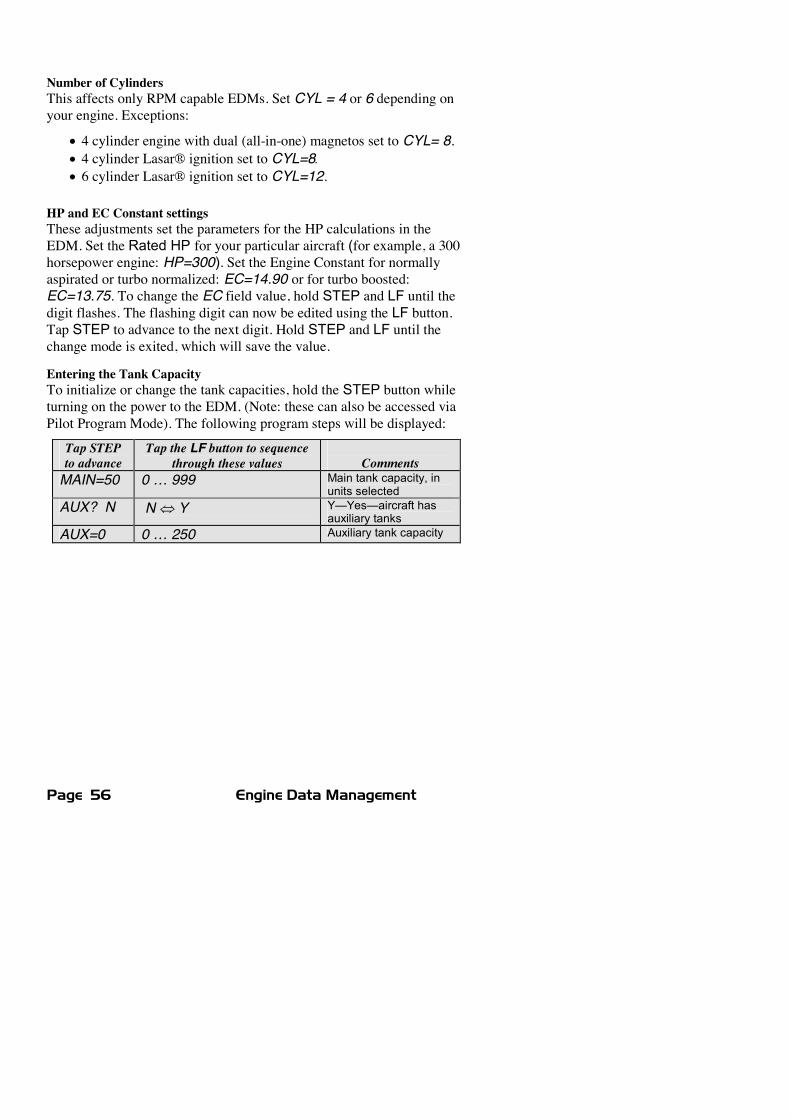
Page 56 Engine Data Management
Number of CylindersThis affects only RPM capable EDMs. Set CYL = 4 or 6 depending onyour engine. Exceptions:
x 4 cylinder engine with dual (all-in-one) magnetos set to CYL= 8.x 4 cylinder Lasar® ignition set to CYL=8.x 6 cylinder Lasar® ignition set to CYL=12.
HP and EC Constant settingsThese adjustments set the parameters for the HP calculations in theEDM. Set the Rated HP for your particular aircraft (for example, a 300horsepower engine: HP=300). Set the Engine Constant for normallyaspirated or turbo normalized: EC=14.90 or for turbo boosted:EC=13.75. To change the EC field value, hold STEP and LF until thedigit flashes. The flashing digit can now be edited using the LF button.Tap STEP to advance to the next digit. Hold STEP and LF until thechange mode is exited, which will save the value.
Entering the Tank CapacityTo initialize or change the tank capacities, hold the STEP button whileturning on the power to the EDM. (Note: these can also be accessed viaPilot Program Mode). The following program steps will be displayed:
Tap STEPto advance
Tap the LF button to sequencethrough these values Comments
MAIN=50 0 … 999 Main tank capacity, inunits selected
AUX? N N� Y Y—Yes—aircraft hasauxiliary tanks
AUX=0 0 … 250 Auxiliary tank capacity
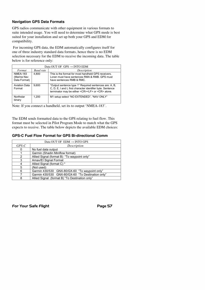
For Your Safe Flight Page 57
Navigation GPS Data FormatsGPS radios communicate with other equipment in various formats tosuite intended usage. You will need to determine what GPS mode is bestsuited for your installation and set up both your GPS and EDM forcompatibility.
For incoming GPS data, the EDM automatically configures itself forone of three industry standard data formats, hence there is no EDMselection necessary for the EDM to receive the incoming data. The tablebelow is for reference only:
Data OUT OF GPSĺ INTO EDMFormat Baud rate Description
NMEA-183(Marine NavData Format)
4,800 This is the format for most handheld GPS receivers.Loran must have sentences RMA & RMB. GPS musthave sentences RMB & RMC.
Aviation DataFormat
9,600 “Output sentence type 1” Required sentences are: A, B,C, D, E, I and L first character identifier byte. Sentenceterminator may be either <CR><LF> or <CR> alone.
Northstarbinary
1,200 M1 setup select “NO EXTENDED”, “NAV ONLY”
Note: If you connect a handheld, set its to output ‘NMEA-183’.
The EDM sends formatted data to the GPS relating to fuel flow. Thisformat must be selected in Pilot Program Mode to match what the GPSexpects to receive. The table below depicts the available EDM choices:
GPS-C Fuel Flow Format for GPS Bi-directional CommData OUT OF EDMĺ�INTO GPS
GPS-C Description0 No fuel data output1 Garmin (Shadin Miniflow format)2 Allied Signal (format B) “To waypoint only”3 Arnav/EI Signal Format4 Allied Signal (format C) *5 (Not used)6 Garmin 430/530 GNX-80/GX-60 “To waypoint only”7 Garmin 430/530 GNX-80/GX-60 “To Destination only”8 Allied Signal (format B) “To Destination only”
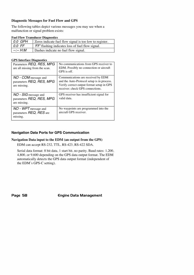
Page 58 Engine Data Management
Diagnostic Messages for Fuel Flow and GPSThe following tables depict various messages you may see when amalfunction or signal problem exists:
Fuel Flow Transducer Diagnostics0.0 GPH Zeros indicate fuel flow signal is too low to register.0.0 FF ‘FF’ flashing indicates loss of fuel flow signal.--:-- H:M Dashes indicate no fuel flow signal.
GPS Interface DiagnosticsParameters REQ, RES, MPGare all missing from the scan.
No communications from GPS receiver toEDM. Possibly no connection or aircraftGPS is off.
NO - COM message andparameters REQ, RES, MPGare missing.
Communications are received by EDMand the Auto-Protocol setup is in process.Verify correct output format setup in GPSreceiver; check GPS connections.
NO - SIG message andparameters REQ, RES, MPGare missing.
GPS receiver has insufficient signal forvalid data.
NO - WPT message andparameters REQ, RES aremissing.
No waypoints are programmed into theaircraft GPS receiver.
Navigation Data Ports for GPS Communication
Navigation Data input to the EDM (an output from the GPS)EDM can accept RS-232, TTL, RS-423, RS-422 SDA.
Serial data format: 8 bit data, 1 start bit, no parity. Baud rates: 1,200,4,800, or 9,600 depending on the GPS data output format. The EDMautomatically detects the GPS data output format (independent ofthe EDM’s GPS-C setting).
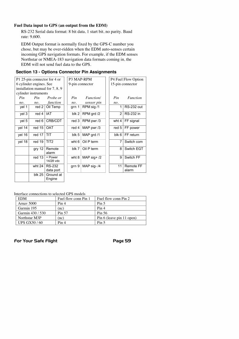
For Your Safe Flight Page 59
Fuel Data input to GPS (an output from the EDM)RS-232 Serial data format: 8 bit data, 1 start bit, no parity. Baudrate: 9,600.
EDM Output format is normally fixed by the GPS-C number youchose, but may be over-ridden when the EDM auto-senses certainincoming GPS navigation formats. For example, if the EDM sensesNorthstar or NMEA-183 navigation data formats coming in, theEDM will not send fuel data to the GPS.
Section 13 - Options Connector Pin AssignmentsP1 25-pin connector for 4 or6 cylinder engines. Seeinstallation manual for 7, 8, 9cylinder instruments
P3 MAP-RPM9-pin connector
P4 Fuel Flow Option15-pin connector
Pinno.
Pinno.
Probe orfunction
Pinno.
Function/sensor pin
Pinno.
Function
yel 1 red 2 Oil Temp grn 1 RPM sig /1 1 RS-232 out
yel 3 red 4 IAT blk 2 RPM grd /2 2 RS-232 in
yel 5 red 6 CRB/CDT red 3 RPM pwr /3 wht 4 FF signal
yel 14 red 15 OAT red 4 MAP pwr /3 red 5 FF power
yel 16 red 17 TIT blk 5 MAP grd /1 blk 6 FF return
yel 18 red 19 TIT2 wht 6 Oil P term 7 Switch com
gry 12 Remotealarm
blk 7 Oil P term 8 Switch EGT
red 13 + Power14/28 vdc
wht 8 MAP sig+ /2 9 Switch FF
wht 24 RS-232data port
grn 9 MAP sig- /4 11 Remote FFalarm
blk 25 Ground atEngine
Interface connections to selected GPS modelsEDM Fuel flow conn Pin 1 Fuel flow conn Pin 2Arnav 5000 Pin 4 Pin 5Garmin 195 (nc) Pin 4Garmin 430 / 530 Pin 57 Pin 56Northstar M3P (nc) Pin 6 (leave pin 11 open)UPS GX50 / 60 Pin 4 Pin 5
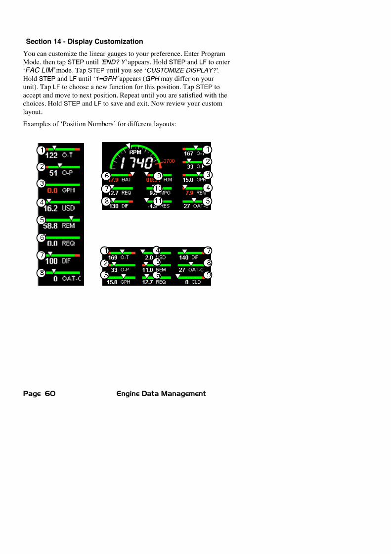
Page 60 Engine Data Management
Section 14 - Display CustomizationYou can customize the linear gauges to your preference. Enter ProgramMode, then tap STEP until ‘END? Y’ appears. Hold STEP and LF to enter‘FAC LIM’mode. Tap STEP until you see ‘CUSTOMIZE DISPLAY?’.Hold STEP and LF until ‘1=GPH’ appears (GPH may differ on yourunit). Tap LF to choose a new function for this position. Tap STEP toaccept and move to next position. Repeat until you are satisfied with thechoices. Hold STEP and LF to save and exit. Now review your customlayout.
Examples of ‘Position Numbers’ for different layouts:

For Your Safe Flight Page 61
Section 15 - Reference ReadingYou may wish to know more about the effect of engine operations onEGT and CHT. The reading list below provides general overviews aswell as original references on topics that may be of interest.
General OverviewThese references are readily available to pilots and provide a readablesource of general technical information.
x Teledyne Continental Motors, Engine Operation for Pilots, from theFAA Accident Prevention Program, FAA-P-8740-13.
x Editors of Light Plane MaintenanceMagazine, EGT Systems,Belvoir Publications Inc., Greenwich, CT 06836. 1989.
x Lycoming Flyer Issue 53 dated January 93.Technical Reviews and Original ReferencesFor those pilots who have engineering backgrounds, the references listedbelow present the original research on the combustion process andrepresent the source documents for those with technical interests.
x A. Hundere, “Autogas for Avgas,” AOPA Pilot, October, 1969.x A. Hundere and J. Bert, “Pre-ignition and Its Deleterious Effects inAircraft Engines,” SAE Quarterly Transactions, Vol. 2, No. 4, pages547-562, October 1948.
Section 16 - Technical Support
JPI offers both e-mail ([email protected]) and telephone technicalsupport. Have your model and serial number ready when you call. CallJPI for a return authorization numberRMA before returning anyequipment.
J.P. INSTRUMENTS Inc.3185 B AirwayCosta Mesa, CA 92626
800 345-4574714 557 3805Fax 714-557-9840www.jpinstruments.com and www.jpitech.com
Page 62 Engine Data Management
Section 17 - Limited WarrantyJ.P. Instruments Inc. (JPI) warrants all parts in your new EDM to be freefrom defects in material and workmanship under normal use. Ourobligation under this warranty is limited to repair or exchange of anydefective part of this unit if the part is returned, shipping prepaid, withinthree years for electronics and one year for probes from the date oforiginal purchase. Installation labor is the responsibility of the aircraftowner. Homebuilt aircraft warranty starts when the aircraft is certifiedfor flight. Replacement parts carry a warranty for the balance of thewarranty period.
Under this warranty, JPI is not responsible for any service charges,including removal, installation, nor any other consequential damages.JPI incurs no obligation under this warranty unless a WarrantyRegistration Certificate describing the warranted product has beencompleted and mailed to JPI with all information requested.
This warranty is void on any product which has been subject to misuse,accident, damage caused by negligence, damage in transit, handling ormodification which, in the opinion of JPI, has altered or repaired theproduct in any way that effects the reliability or detracts from theperformance of the product, or any product whereon the serial numberhas been altered, defaced, effaced or destroyed.
This warranty is in lieu of all other warranties expressed or implied andother obligations of liability on JPI’s part, and it neither assumes norauthorizes any other person to assume for JPI any other liability inconnection with the sale of JPI products.
To initiate this warranty, the aircraft owner must submit a completedData Logging Worksheet to JPI. Upon receiving a completed worksheet,JPI will initiate the warranty from the date of original purchase. Anyreplacement parts carry a warranty that extends for the balance of theperiod of the original warranty. For homebuilt aircraft the warranty startswhen the aircraft is certificated for flight and noted on the warranty card.

For Your Safe Flight Page 63
Section 18 - EDM-851 TWIN ENGINE ADDENDUM
The following provides instructions for install / operation of the EDM-851 Twin
Engine configuration. Each EDM-830 instrument is installed to its respective engine
as if it were a single. One EDM operates as a ‘Master’, and the other operates as a
‘Slave’. This allows each instruments fuel computer values, such as total fuel
remaining, total fuel used, hours of endurance and so on, to be combined and
displayed on the Master.
The main differences for the twin installation (versus a single) are:
1. An interconnect cable (JPI PN 700725) is installed between the two
instruments, allowing them to cross-communicate. See ‘Illustration A’ below.
2. The right engine EDM acts as a ‘Slave’ unit and certain connections must be
made as follows:
a. If you do have the fuel flow option, install the supplied P4 harness (JPI
PN 700709-4) to the ‘Slave’ EDM. Install the other P4 harness (JPI PN
700709 no dash number) to the ‘Master’ EDM. Note: EDM <-> GPS
connections are only made between the GPS radio and the ‘Master’
EDM. None are made to the ‘Slave’ EDM.
b. If you do not have the fuel flow option, install the supplied P4 plug (JPI
PN 700709-5) to the ‘Slave’ EDM.
The following are reminders regarding installation requirements that must befollowed:
- Each EDM unit shall be powered by a dedicated circuit breaker.
- Each EDM unit shall be grounded directly to the engine that it is monitoring
(not the aircraft ground bus).
- Pilot Programming Mode and Factory Limits Mode should be performed on
each EDM unit to match them to the installation requirements. NOTE: these
parameters are intentionally not synchronized between the units. You must
program BOTH EDM’s.
Page 64 Engine Data Management
Section 19 - Index* Pre-leaning procedure:, 25
AAccumulate, 46, 51total, 42
Adapter probe, CHT, 32AdjustingK-factor, 49OAT, 46TIT, factory original, 48
Alarm Display Lights, 60Alarm limitschanging, 52factory defaults, 52fuel flow, 55
Alarms, 35low fuel, 55priority, 36resetting, 36
ALL, 47select switch, 42
Allied Signal, 57Automatic indexing mode, 15Automatic mode, 20AUX, 54, 56Auxiliary tanks, 55Avgas, 36Aviation data format, 57
BBaud rate, 58Blinking display, 23, 24, 28, 35, 37Brightness, display, 8Buttonsfront panel, 16
CCalibrationhorsepower, 47internal self test, 20K-factor, 49manifold pressure (MAP), 47OAT, 46TIT, factory original, 48
CARB?, 54Carburetor, 55, 56
ice, 34temperature, 43
Celsiusengine temperatures, 53OAT, 46
Changing alarm limits, 52CHTdisplay, 14probe, 6, 32too high or too low, 32, 35
Climb, 29Combustion, 6, 36, 61Compression, 6, 34high, 36low, 33
Compressor discharge temperature,CDT, 43
Connectoroption pins, 59
Cowling, obstruction, 34Custom programming, 45alarm limits, 52fuel flow option, 49Long Term Memory Option, 51
Cylinder numbers, 10
DDataGPS formats, 57ports, GPS, 58
Default alarm limits, 52Descent, 30Detonation, 35, 36Diagnosing engine problems, 32, 36,48, 49, 52
Diagnosticfuel flow messages, 58GPS interface messages, 58self test, 20
DIF, 35, 43, 53Dimming, display, 8DisplayCHT, 14digital, 10, 11EGT, 14flashing, 23, 24, 28, 35, 37TIT, 15
Dot index, 10
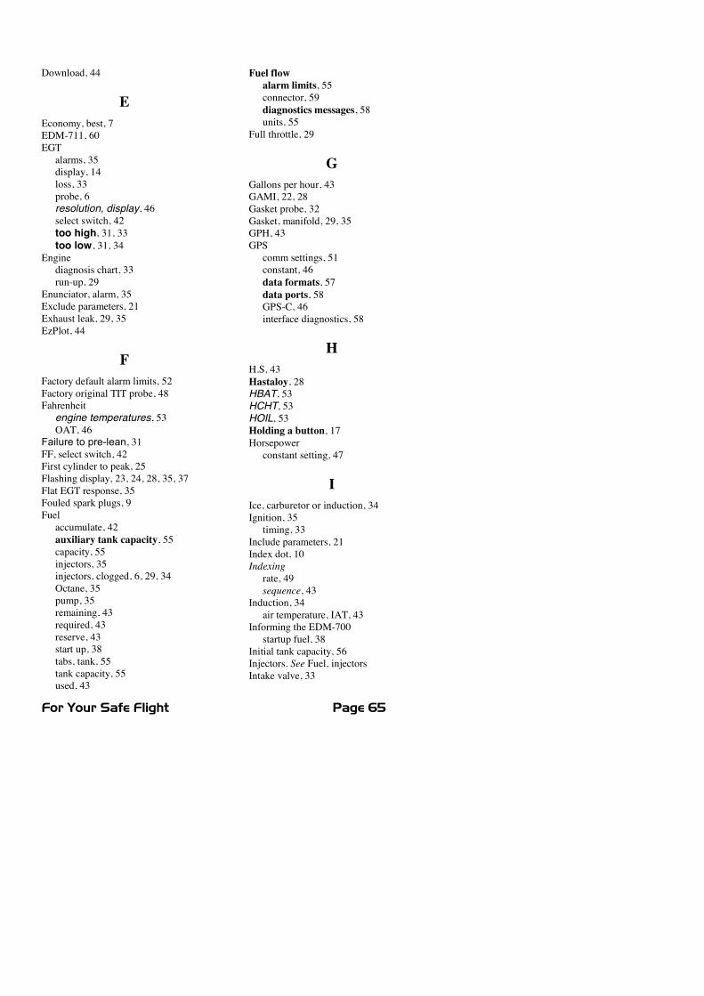
For Your Safe Flight Page 65
Download, 44
EEconomy, best, 7EDM-711, 60EGTalarms, 35display, 14loss, 33probe, 6resolution, display, 46select switch, 42too high, 31, 33too low, 31, 34
Enginediagnosis chart, 33run-up, 29
Enunciator, alarm, 35Exclude parameters, 21Exhaust leak, 29, 35EzPlot, 44
FFactory default alarm limits, 52Factory original TIT probe, 48Fahrenheit
engine temperatures, 53OAT, 46
Failure to pre-lean, 31FF, select switch, 42First cylinder to peak, 25Flashing display, 23, 24, 28, 35, 37Flat EGT response, 35Fouled spark plugs, 9Fuelaccumulate, 42auxiliary tank capacity, 55capacity, 55injectors, 35injectors, clogged, 6, 29, 34Octane, 35pump, 35remaining, 43required, 43reserve, 43start up, 38tabs, tank, 55tank capacity, 55used, 43
Fuel flowalarm limits, 55connector, 59diagnostics messages, 58units, 55
Full throttle, 29
GGallons per hour, 43GAMI, 22, 28Gasket probe, 32Gasket, manifold, 29, 35GPH, 43GPScomm settings, 51constant, 46data formats, 57data ports, 58GPS-C, 46interface diagnostics, 58
HH.S, 43Hastaloy, 28HBAT, 53HCHT, 53HOIL, 53Holding a button, 17Horsepowerconstant setting, 47
IIce, carburetor or induction, 34Ignition, 35timing, 33
Include parameters, 21Index dot, 10Indexingrate, 49sequence, 43
Induction, 34air temperature, IAT, 43
Informing the EDM-700startup fuel, 38
Initial tank capacity, 56Injectors. See Fuel, injectorsIntake valve, 33
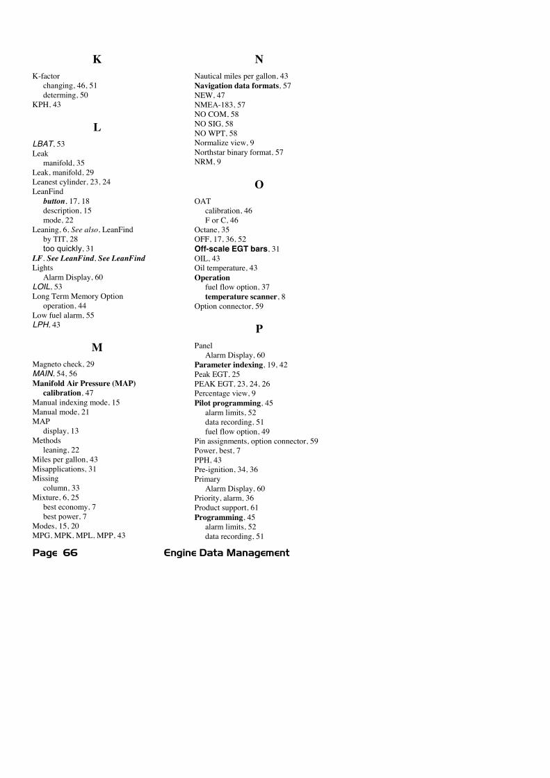
Page 66 Engine Data Management
KK-factorchanging, 46, 51determing, 50
KPH, 43
LLBAT, 53Leakmanifold, 35
Leak, manifold, 29Leanest cylinder, 23, 24LeanFindbutton, 17, 18description, 15mode, 22
Leaning, 6, See also, LeanFindby TIT, 28too quickly, 31
LF. See LeanFind, See LeanFindLightsAlarm Display, 60
LOIL, 53Long Term Memory Optionoperation, 44
Low fuel alarm, 55LPH, 43
MMagneto check, 29MAIN, 54, 56Manifold Air Pressure (MAP)calibration, 47
Manual indexing mode, 15Manual mode, 21MAPdisplay, 13
Methodsleaning, 22
Miles per gallon, 43Misapplications, 31Missingcolumn, 33
Mixture, 6, 25best economy, 7best power, 7
Modes, 15, 20MPG, MPK, MPL, MPP, 43
NNautical miles per gallon, 43Navigation data formats, 57NEW, 47NMEA-183, 57NO COM, 58NO SIG, 58NO WPT, 58Normalize view, 9Northstar binary format, 57NRM, 9
OOATcalibration, 46F or C, 46
Octane, 35OFF, 17, 36, 52Off-scale EGT bars, 31OIL, 43Oil temperature, 43Operationfuel flow option, 37temperature scanner, 8
Option connector, 59
PPanelAlarm Display, 60
Parameter indexing, 19, 42Peak EGT, 25PEAK EGT, 23, 24, 26Percentage view, 9Pilot programming, 45alarm limits, 52data recording, 51fuel flow option, 49
Pin assignments, option connector, 59Power, best, 7PPH, 43Pre-ignition, 34, 36PrimaryAlarm Display, 60
Priority, alarm, 36Product support, 61Programming, 45alarm limits, 52data recording, 51
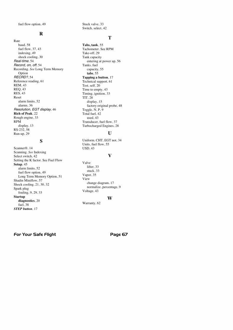
For Your Safe Flight Page 67
fuel flow option, 49
RRatebaud, 58fuel flow, 37, 43indexing, 49shock cooling, 30
Real-time, 54Record, on, off, 54Recording. See Long Term MemoryOption
RECRD?, 54Reference reading, 61REM, 43REQ, 43RES, 43Resetalarm limits, 52alarms, 36
Resolution, EGT display, 46Rich of Peak, 22Rough engine, 33RPMdisplay, 13
RS-232, 58Run-up, 29
SScanner®, 14Scanning. See IndexingSelect switch, 42Setting the K factor. See Fuel FlowSetup, 45alarm limits, 52fuel flow option, 49Long Term Memory Option, 51
Shadin Miniflow, 57Shock cooling, 21, 30, 32Spark plugfouling, 9, 29, 33
Startupdiagnostics, 20fuel, 38
STEP button, 17
Stuck valve, 33Switch, select, 42
TTabs, tank, 55Tachometer. See RPMTake-off, 29Tank capacityentering at power up, 56
Tanks, fuelcapacity, 55tabs, 55
Tapping a button, 17Technical support, 61Test, self, 20Time to empty, 43Timing, ignition, 33TIT, 28display, 15factory original probe, 48
Toggle, N, P, 9Total fuel, 42used, 43
Transducer, fuel flow, 37Turbocharged Engines, 28
UUniform, CHT, EGT not, 34Units, fuel flow, 55USD, 43
VValvelifter, 33stuck, 33
Vapor, 35Viewchange diagram, 17normalize, percentage, 9
Voltage, 43
WWarranty, 62
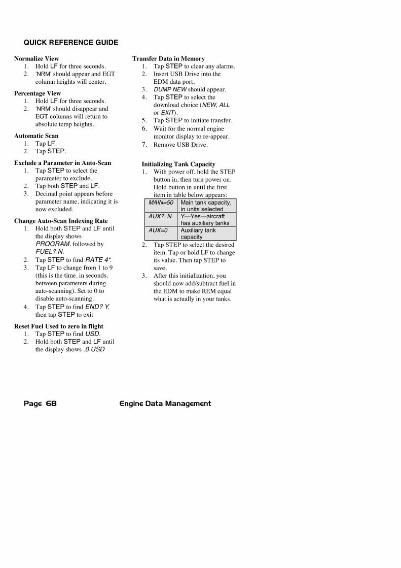
Page 68 Engine Data Management
QUICK REFERENCE GUIDE
Normalize View1. Hold LF for three seconds.2. ‘NRM’ should appear and EGT
column heights will center.
Percentage View1. Hold LF for three seconds.2. ‘NRM’ should disappear and
EGT columns will return toabsolute temp heights.
Automatic Scan1. Tap LF.2. Tap STEP.
Exclude a Parameter in Auto-Scan1. Tap STEP to select the
parameter to exclude.2. Tap both STEP and LF.3. Decimal point appears before
parameter name, indicating it isnow excluded.
Change Auto-Scan Indexing Rate1. Hold both STEP and LF until
the display showsPROGRAM, followed byFUEL? N.
2. Tap STEP to find RATE 4*.3. Tap LF to change from 1 to 9
(this is the time, in seconds,between parameters duringauto-scanning). Set to 0 todisable auto-scanning.
4. Tap STEP to find END? Y,then tap STEP to exit
Reset Fuel Used to zero in flight1. Tap STEP to find USD.2. Hold both STEP and LF until
the display shows .0 USD
Transfer Data in Memory1. Tap STEP to clear any alarms.2. Insert USB Drive into the
EDM data port.3. DUMP NEW should appear.4. Tap STEP to select the
download choice (NEW, ALLor EXIT).
5. Tap STEP to initiate transfer.6. Wait for the normal engine
monitor display to re-appear.7. Remove USB Drive.
Initializing Tank Capacity1. With power off, hold the STEP
button in, then turn power on.Hold button in until the firstitem in table below appears:
MAIN=50 Main tank capacity,in units selected
AUX? N Y—Yes—aircrafthas auxiliary tanks
AUX=0 Auxiliary tankcapacity
2. Tap STEP to select the desireditem. Tap or hold LF to changeits value. Then tap STEP tosave.
3. After this initialization, youshould now add/subtract fuel inthe EDM to make REM equalwhat is actually in your tanks.
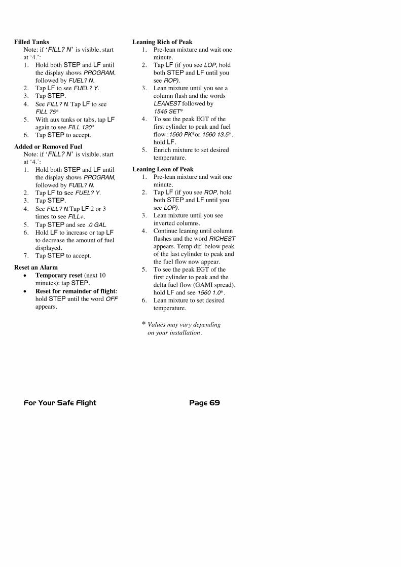
For Your Safe Flight Page 69
Filled TanksNote: if ‘FILL? N’ is visible, startat ‘4.’:1. Hold both STEP and LF until
the display shows PROGRAM,followed by FUEL? N.
2. Tap LF to see FUEL? Y.3. Tap STEP.4. See FILL? N. Tap LF to see
FILL 75*5. With aux tanks or tabs, tap LF
again to see FILL 120*6. Tap STEP to accept.
Added or Removed FuelNote: if ‘FILL? N’ is visible, startat ‘4.’:1. Hold both STEP and LF until
the display shows PROGRAM,followed by FUEL? N.
2. Tap LF to see FUEL? Y.3. Tap STEP.4. See FILL? N.Tap LF 2 or 3
times to see FILL+.5. Tap STEP and see .0 GAL.6. Hold LF to increase or tap LF
to decrease the amount of fueldisplayed.
7. Tap STEP to accept.
Reset an Alarmx Temporary reset (next 10
minutes): tap STEP.x Reset for remainder of flight:
hold STEP until the word OFFappears.
Leaning Rich of Peak1. Pre-lean mixture and wait one
minute.2. Tap LF (if you see LOP, hold
both STEP and LF until yousee ROP).
3. Lean mixture until you see acolumn flash and the wordsLEANEST followed by1545 SET*
4. To see the peak EGT of thefirst cylinder to peak and fuelflow :1560 PK*or 1560 13.5*,hold LF.
5. Enrich mixture to set desiredtemperature.
Leaning Lean of Peak1. Pre-lean mixture and wait one
minute.2. Tap LF (if you see ROP, hold
both STEP and LF until yousee LOP).
3. Lean mixture until you seeinverted columns.
4. Continue leaning until columnflashes and the word RICHESTappears. Temp dif below peakof the last cylinder to peak andthe fuel flow now appear.
5. To see the peak EGT of thefirst cylinder to peak and thedelta fuel flow (GAMI spread),hold LF and see 1560 1.0*.
6. Lean mixture to set desiredtemperature.
* Values may vary dependingon your installation.
For Your Safe Flight Page 70
Pilot’s GuideSupplementEngine Data Management
EDM-740 ExperimentalModel
Copyright � 2009 J.P. Instruments, Inc.
All Rights Reserved
J.P. INSTRUMENTS INC.Information: P. O. Box 7033Huntington Beach, CA 92646Factory: 3185 B AirwayCosta Mesa, CA 92626
PH: (714) 557-5434PH: (800) 345-4574FX: (714) 557-9840www.jpinstruments.comwww.jpitech.comwww.BuyJPI.comSupport@jpitech.com
Printed in the United States of America Rev NC 11/17/2009Last printed 3/11/2011 8:44:00 AM
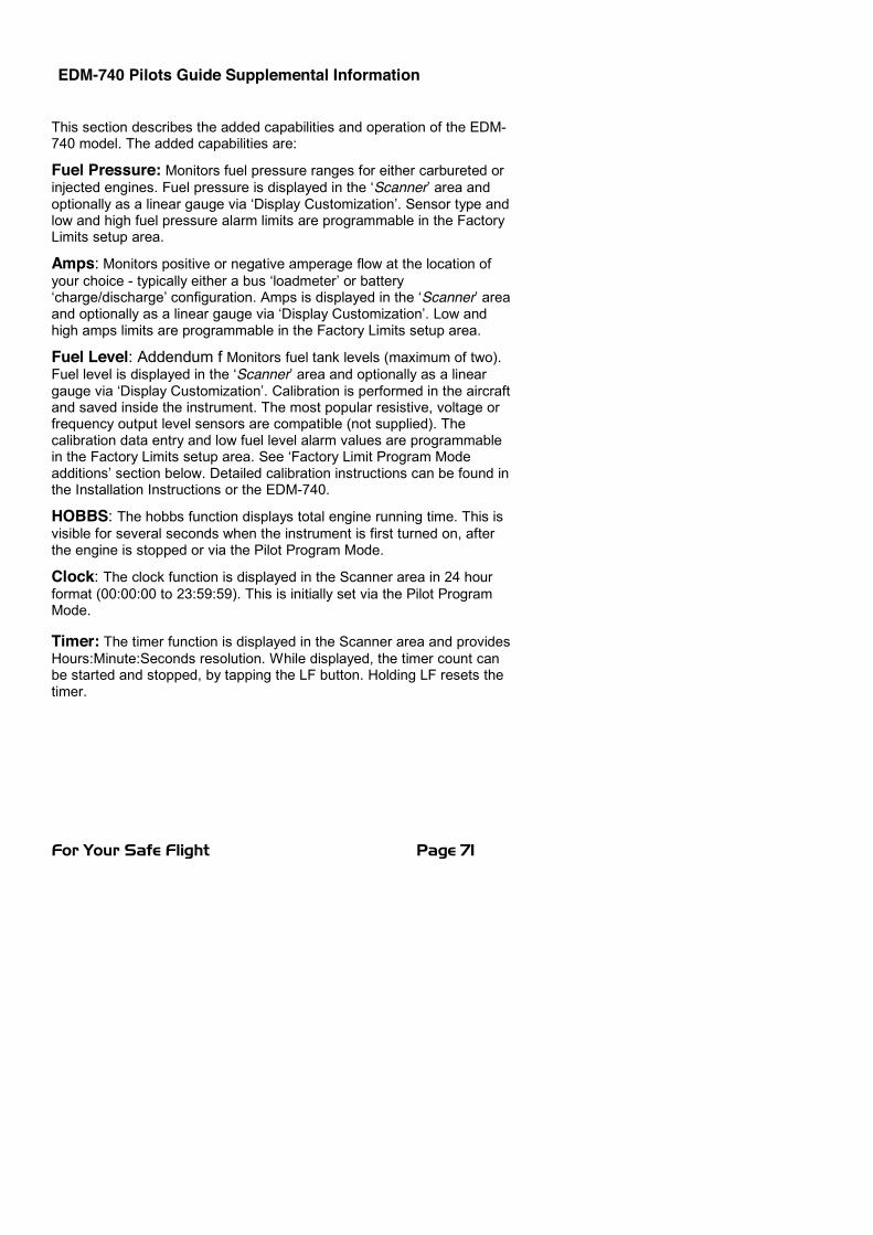
EDM-740 Pilots Guide Supplemental Information
For Your Safe Flight Page 71
This section describes the added capabilities and operation of the EDM-740 model. The added capabilities are:
Fuel Pressure: Monitors fuel pressure ranges for either carbureted orinjected engines. Fuel pressure is displayed in the ‘Scanner’ area andoptionally as a linear gauge via ‘Display Customization’. Sensor type andlow and high fuel pressure alarm limits are programmable in the FactoryLimits setup area.
Amps: Monitors positive or negative amperage flow at the location ofyour choice - typically either a bus ‘loadmeter’ or battery‘charge/discharge’ configuration. Amps is displayed in the ‘Scanner’ areaand optionally as a linear gauge via ‘Display Customization’. Low andhigh amps limits are programmable in the Factory Limits setup area.
Fuel Level: Addendum f Monitors fuel tank levels (maximum of two).Fuel level is displayed in the ‘Scanner’ area and optionally as a lineargauge via ‘Display Customization’. Calibration is performed in the aircraftand saved inside the instrument. The most popular resistive, voltage orfrequency output level sensors are compatible (not supplied). Thecalibration data entry and low fuel level alarm values are programmablein the Factory Limits setup area. See ‘Factory Limit Program Modeadditions’ section below. Detailed calibration instructions can be found inthe Installation Instructions or the EDM-740.
HOBBS: The hobbs function displays total engine running time. This isvisible for several seconds when the instrument is first turned on, afterthe engine is stopped or via the Pilot Program Mode.
Clock: The clock function is displayed in the Scanner area in 24 hourformat (00:00:00 to 23:59:59). This is initially set via the Pilot ProgramMode.
Timer: The timer function is displayed in the Scanner area and providesHours:Minute:Seconds resolution. While displayed, the timer count canbe started and stopped, by tapping the LF button. Holding LF resets thetimer.
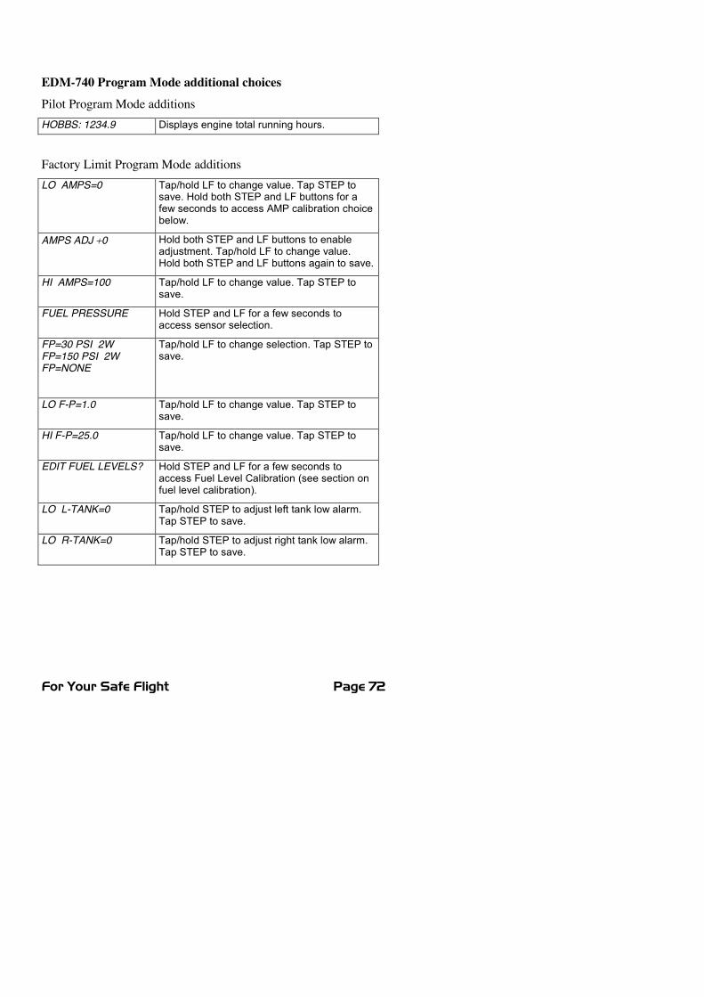
For Your Safe Flight Page 72
EDM-740 Program Mode additional choicesPilot Program Mode additionsHOBBS: 1234.9 Displays engine total running hours.
Factory Limit Program Mode additionsLO AMPS=0 Tap/hold LF to change value. Tap STEP to
save. Hold both STEP and LF buttons for afew seconds to access AMP calibration choicebelow.
AMPS ADJ �0 Hold both STEP and LF buttons to enableadjustment. Tap/hold LF to change value.Hold both STEP and LF buttons again to save.
HI AMPS=100 Tap/hold LF to change value. Tap STEP tosave.
FUEL PRESSURE Hold STEP and LF for a few seconds toaccess sensor selection.
FP=30 PSI 2WFP=150 PSI 2WFP=NONE
Tap/hold LF to change selection. Tap STEP tosave.
LO F-P=1.0 Tap/hold LF to change value. Tap STEP tosave.
HI F-P=25.0 Tap/hold LF to change value. Tap STEP tosave.
EDIT FUEL LEVELS? Hold STEP and LF for a few seconds toaccess Fuel Level Calibration (see section onfuel level calibration).
LO L-TANK=0 Tap/hold STEP to adjust left tank low alarm.Tap STEP to save.
LO R-TANK=0 Tap/hold STEP to adjust right tank low alarm.Tap STEP to save.
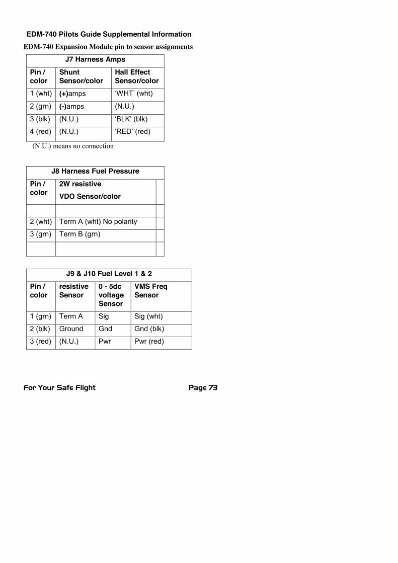
EDM-740 Pilots Guide Supplemental Information
For Your Safe Flight Page 73
EDM-740 Expansion Module pin to sensor assignments
J7 Harness AmpsPin /color
ShuntSensor/color
Hall EffectSensor/color
1 (wht) (+)amps ‘WHT’ (wht)
2 (grn) (-)amps (N.U.)
3 (blk) (N.U.) ‘BLK’ (blk)
4 (red) (N.U.) ‘RED’ (red)
(N.U.) means no connection
J8 Harness Fuel PressurePin /color
2W resistiveVDO Sensor/color
2 (wht) Term A (wht) No polarity
3 (grn) Term B (grn)
J9 & J10 Fuel Level 1 & 2Pin /color
resistiveSensor
0 - 5dcvoltageSensor
VMS FreqSensor
1 (grn) Term A Sig Sig (wht)
2 (blk) Ground Gnd Gnd (blk)
3 (red) (N.U.) Pwr Pwr (red)