Embed Size (px)
Citation preview
1
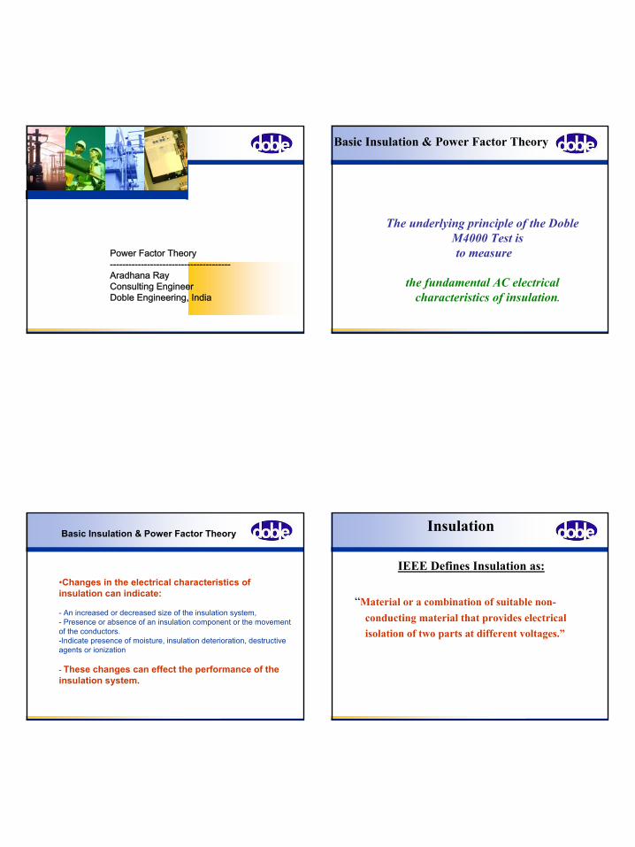
Power Factor Theory---------------------------------------Aradhana RayConsulting Engineer Doble Engineering, India
Basic Insulation & Power Factor Theory
The underlying principle of the Doble M4000 Test isto measure
the fundamental AC electrical characteristics of insulation.
•Changes in the electrical characteristics of insulation can indicate:
- An increased or decreased size of the insulation system,- Presence or absence of an insulation component or the movement of the conductors. -Indicate presence of moisture, insulation deterioration, destructive agents or ionization
- These changes can effect the performance of the insulation system.
Basic Insulation & Power Factor Theory Insulation
IEEE Defines Insulation as:
“Material or a combination of suitable non-conducting material that provides electrical isolation of two parts at different voltages.”
2
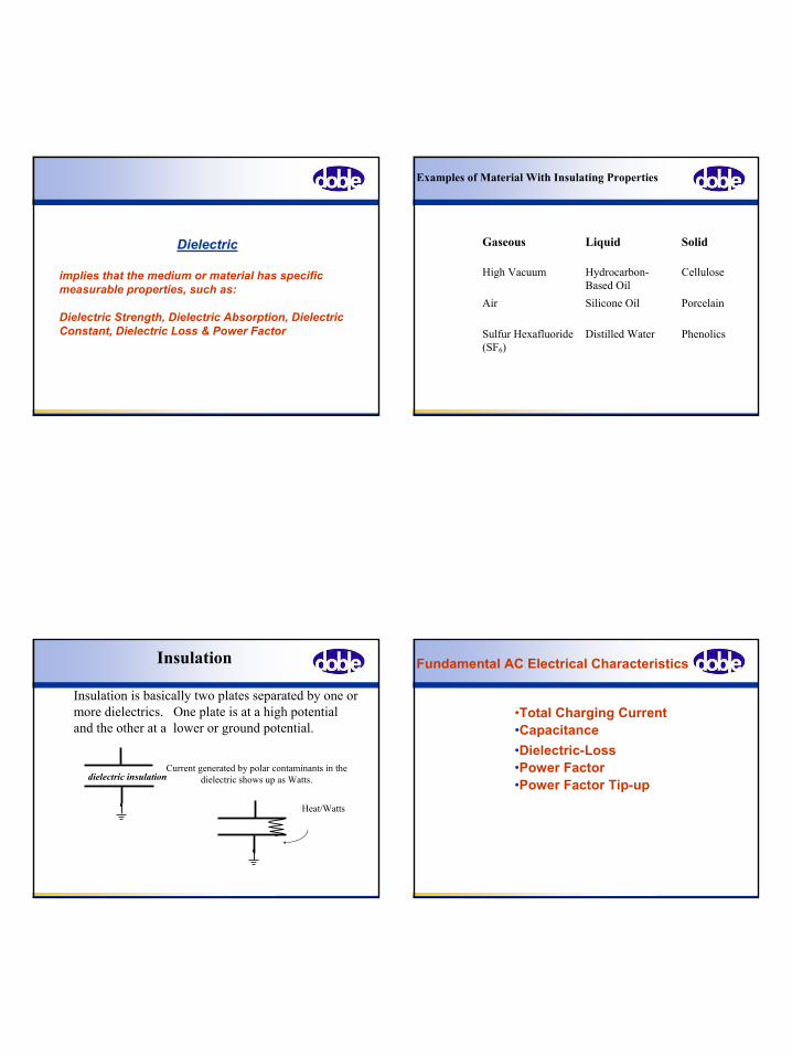
Dielectric
implies that the medium or material has specific measurable properties, such as:
Dielectric Strength, Dielectric Absorption, Dielectric Constant, Dielectric Loss & Power Factor
Examples of Material With Insulating Properties
Gaseous Liquid Solid
High Vacuum Hydrocarbon- Based Oil
Cellulose
Air Silicone Oil Porcelain
Sulfur Hexafluoride (SF6)
Distilled Water Phenolics
Insulation
Insulation is basically two plates separated by one or more dielectrics. One plate is at a high potential and the other at a lower or ground potential.
dielectric insulationCurrent generated by polar contaminants in the
dielectric shows up as Watts.
Heat/Watts
Fundamental AC Electrical Characteristics
•Dielectric-Loss•Power Factor
•Capacitance
•Power Factor Tip-up
•Total Charging Current
3
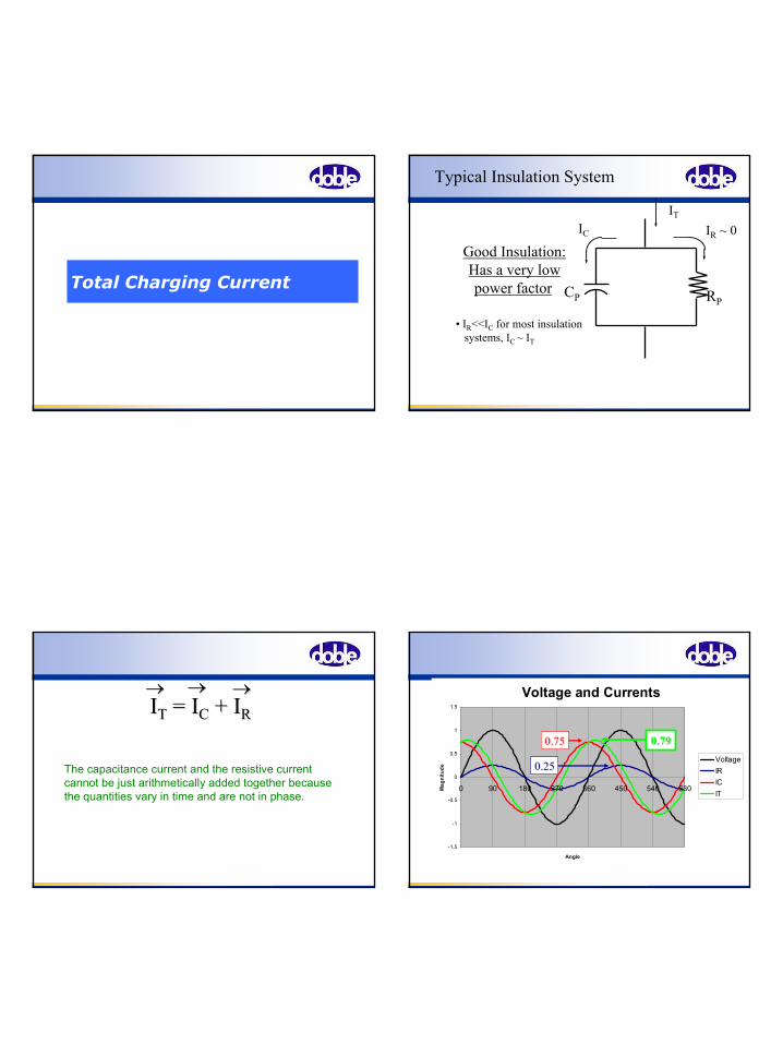
Total Charging Current
Typical Insulation System
Good Insulation:Has a very lowpower factor CP RP
• IR<<IC for most insulationsystems, IC ~ IT
IT
IC IR ~ 0
The capacitance current and the resistive current cannot be just arithmetically added together because the quantities vary in time and are not in phase.
IITT = I= ICC + I+ IRR→→ →→ →→ Voltage and Currents
-1.5
-1
-0.5
0
0.5
1
1.5
0 90 180 270 360 450 540 630
Angle
Mag
nitu
de
VoltageIRICIT
0.750.75
0.250.25
0.790.79
4
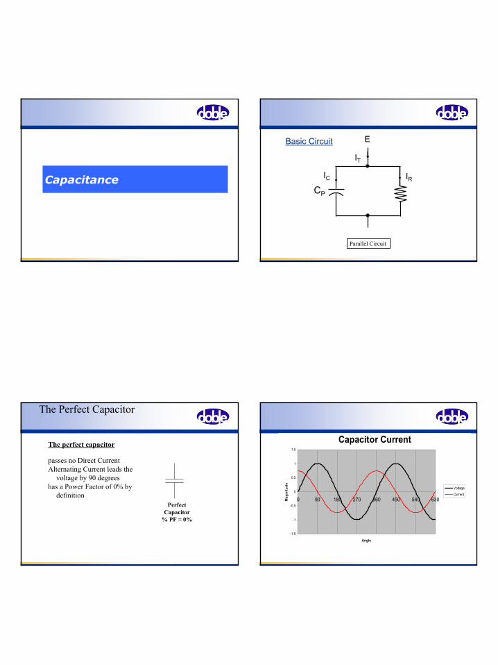
Capacitance
Parallel Circuit
CP
E
IT
IRIC
Basic Circuit
The Perfect Capacitor
The perfect capacitor
passes no Direct CurrentAlternating Current leads the
voltage by 90 degreeshas a Power Factor of 0% by
definitionPerfect
Capacitor% PF = 0%
Capacitor Current
-1.5
-1
-0.5
0
0.5
1
1.5
0 90 180 270 360 450 540 630
Angle
Mag
nitu
de Voltage
Current
5
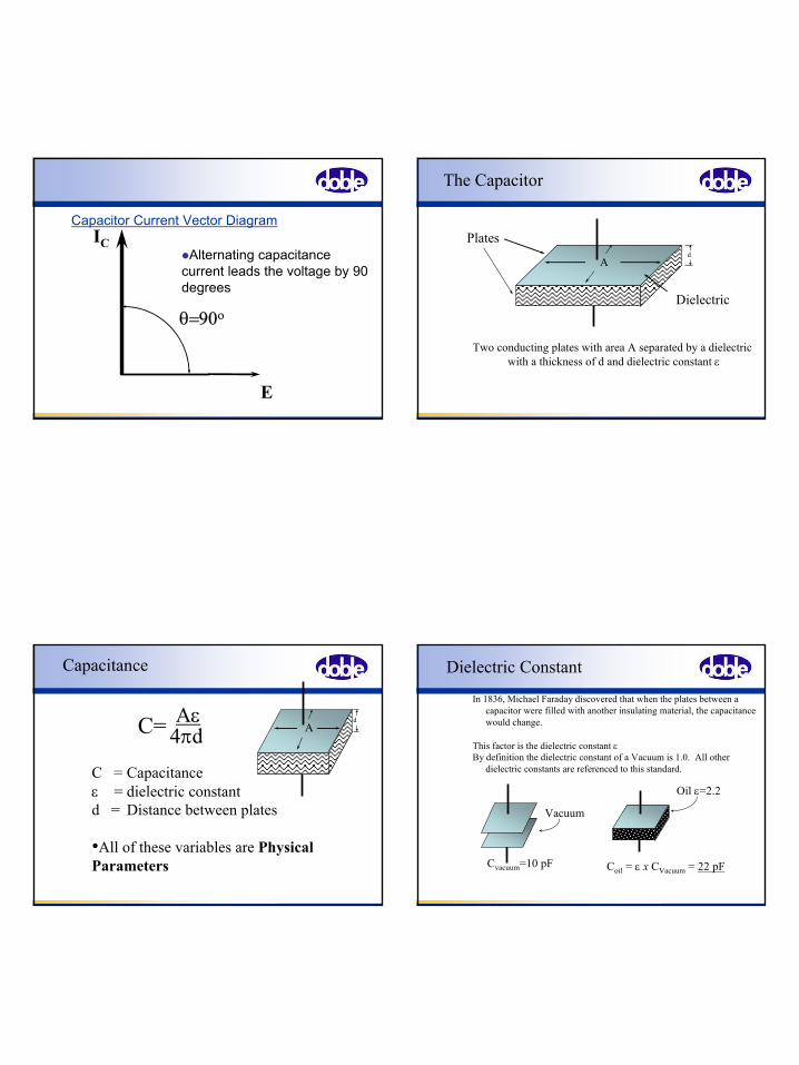
E
IC
θ=90ο
Alternating capacitance current leads the voltage by 90 degrees
Capacitor Current Vector Diagram
The Capacitor
Ad
Two conducting plates with area A separated by a dielectric with a thickness of d and dielectric constant ε
Dielectric
Plates
Capacitance
C = Capacitanceε = dielectric constant d = Distance between plates
•All of these variables are Physical Parameters
AdC= Aε
4πd
Dielectric Constant
In 1836, Michael Faraday discovered that when the plates between a capacitor were filled with another insulating material, the capacitance would change.
This factor is the dielectric constant εBy definition the dielectric constant of a Vacuum is 1.0. All other
dielectric constants are referenced to this standard.
Vacuum
Cvacuum=10 pF
Oil ε=2.2
Coil = ε x CVacuum = 22 pF
6
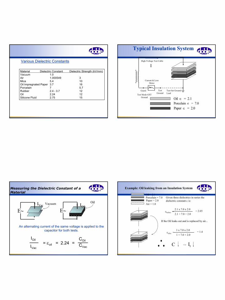
Material Dielectric Constant Dielectric Strength (kV/mm)Vacuum 1.0Air 1.000549 3Mica 5.4 10Oil Impregnated Paper 3.7 16Porcelain 7 5.7Rubber 2.4 - 3.7 12Oil 2.24 12Silicone Fluid 2.75 15
Various Dielectric Constants
Test Mode-GST Ground
Test Ground
Test-Set Ground Lead
High-Voltage Test Cable
Oil = 2.1∈Porcelain = 7.0∈Paper = 2.0∈
Guard
Current & Loss Meter
I
Typical Insulation System
Measuring the Dielectric Constant of a Material
IIOilOilOilOil
IOil COil
CVac== εoil = 2.24
IVac
An alternating current of the same voltage is applied to the capacitor for both tests.
E∼VacuumIIVacVac
E∼
Example: Oil leaking from an Insulation System
Oil = 2.1Porcelain = 7.0Paper = 2.0
Given three dielectrics in series the dielectric constant ε is:
εbefore = 2.1 x 7.0 x 2.0
2.1 + 7.0 + 2.0= 2.65
If the Oil leaks out and is replaced by air...
Air = 1.0
εafter = 1 x 7.0 x 2.0
1 + 7.0 + 2.0= 1.4
C => It
7
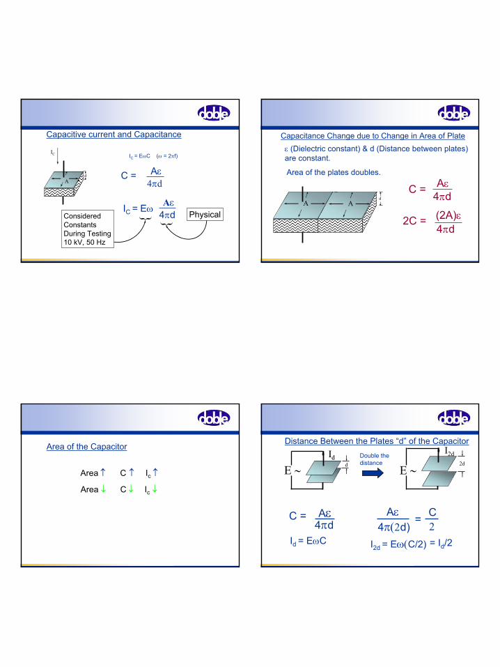
IC = EωC (ω = 2πf)
} Physical}ConsideredConstantsDuring Testing10 kV, 50 Hz
Ad
IC
Capacitive current and Capacitance
C = Aε4πd
IC = EωAε
4πd
d
ε (Dielectric constant) & d (Distance between plates) are constant.
Ad
A
2C =
Capacitance Change due to Change in Area of Plate
Area of the plates doubles.
(2A)ε4πd
C = Aε4πd
Area of the Capacitor
Area ↑ C
Area ↓ C
↑ Ic ↑
↓ Ic ↓
IIdd
E ∼ d
I2d
E ∼2d
C = Aε4πd
I2d = Eω(C/2)
Distance Between the Plates “d” of the Capacitor
Id = EωC
Aε4π(2d)
= C2
Double the distance
= Id/2
8
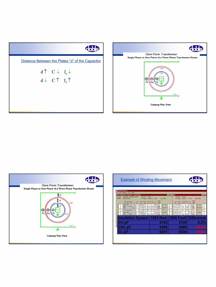
Distance Between the Plates “d” of the Capacitor
d ↑ C
d ↓ C
↓ Ic ↓
↑ Ic ↑
Insulation System 1995 New 1996 Fault DifferenceCH pF 2155 2159 0.2%CHL pF 4360 3886 -10.9%CL pF 8291 9339 12.6%
Example of Winding Movement
9
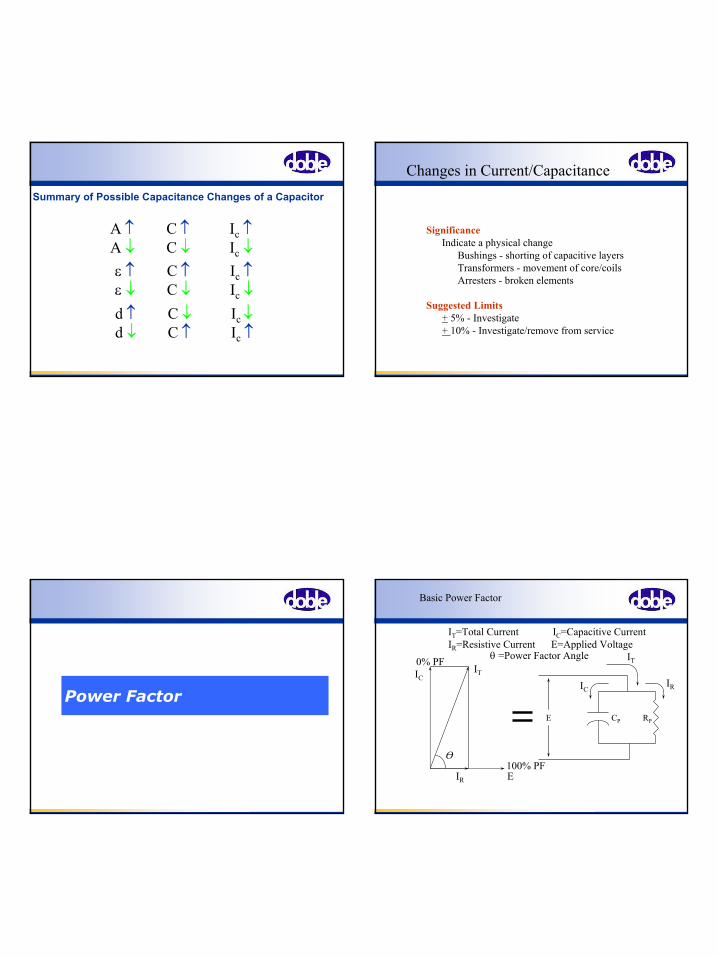
A ↑ C ↑ Ic ↑A ↓ C ↓ Ic ↓
Summary of Possible Capacitance Changes of a Capacitor
ε ↑ C ↑ Ic ↑ε ↓ C ↓ Ic ↓d ↑ C ↓ Ic ↓d ↓ C ↑ Ic ↑
Changes in Current/Capacitance
SignificanceIndicate a physical change
Bushings - shorting of capacitive layersTransformers - movement of core/coilsArresters - broken elements
Suggested Limits+ 5% - Investigate+ 10% - Investigate/remove from service
Power Factor
Basic Power Factor
E CP RP
IT
ICIR
IT=Total Current IC=Capacitive CurrentIR=Resistive Current E=Applied Voltage
ITIC
IR E
O
0% PF
100% PF
θ =Power Factor Angle
10
ITIC
IR E
O
E CP RP
IT
ICIR
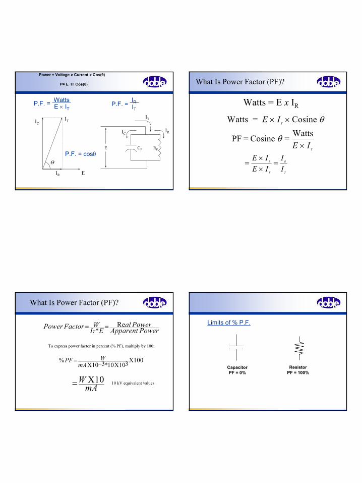
P.F. = WattsE × IT
P.F. = IRIT
P.F. = cosθ
Power = Voltage x Current x Cos(θ)
P= E IT Cos(θ) What Is Power Factor (PF)?
Watts = Cosine E IT
× × θ
PF = Cosine = WattsθE I
T×
=××
=E IE I
II
R
T
R
T
Watts = E x IR
What Is Power Factor (PF)?
=WmAX10
Power Factor WI E
al PowerApparent PowerT
= =*Re
To express power factor in percent (% PF), multiply by 100:
%*
PF WmA
= −X XX
10 3 10 103 100
10 kV equivalent values
Limits of % P.F.
CapacitorPF = 0%
ResistorPF = 100%
11
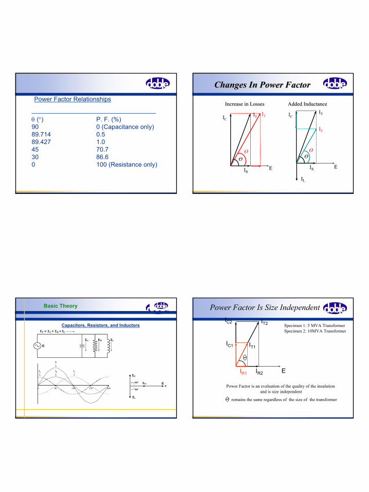
θ (°) P. F. (%)90 0 (Capacitance only)89.714 0.589.427 1.045 70.730 86.60 100 (Resistance only)
Power Factor Relationships
ITIC
IR
O
ITIC
IR
O
IIL
O
EE
IT
EE
O
IT
Increase in LossesIncrease in Losses Added InductanceAdded Inductance
Changes In Power FactorChanges In Power Factor
Capacitors, Resistors, and Inductors
Basic Theory
0 90 180 270 360
IR
↓↓ ↓ILIC
E↓
Power Factor Is Size IndependentIC2
Specimen 1: 5 MVA TransformerSpecimen 2: 10MVA Transformer
remains the same regardless of the size of the transformer
Power Factor is an evaluation of the quality of the insulationand is size independent
IT2
IR2 EIR1
IC1 IT1
12
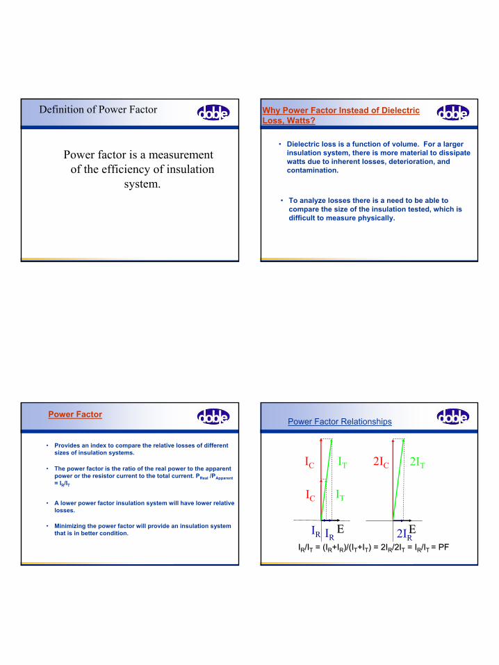
Definition of Power Factor
Power factor is a measurement of the efficiency of insulation
system.
• Dielectric loss is a function of volume. For a larger insulation system, there is more material to dissipate watts due to inherent losses, deterioration, and contamination.
• To analyze losses there is a need to be able to compare the size of the insulation tested, which is difficult to measure physically.
Why Power Factor Instead of Dielectric Loss, Watts?
• Provides an index to compare the relative losses of different sizes of insulation systems.
• The power factor is the ratio of the real power to the apparent power or the resistor current to the total current. PReal /PApparent= IR/IT
• Minimizing the power factor will provide an insulation system that is in better condition.
• A lower power factor insulation system will have lower relative losses.
Power Factor
IC IT
IR EE
IC IT
IREE
2IC 2IT
2IRIIRR/I/ITT = (I= (IRR+I+IRR)/(I)/(ITT+I+ITT) = 2I) = 2IRR/2I/2ITT = I= IRR/I/IT T = PF= PF
Power Factor Relationships
13
Voltage and Currents
-1.5
-1
-0.5
0
0.5
1
1.5
0 90 180 270 360 450 540 630
Angle (360 degrees = 1 / 60th second)
Mag
nitu
de
IC IT
IR EE
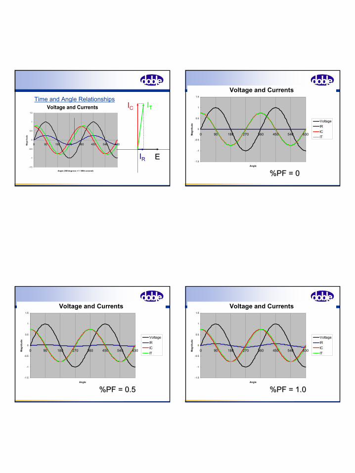
Time and Angle RelationshipsVoltage and Currents
-1.5
-1
-0.5
0
0.5
1
1.5
0 90 180 270 360 450 540 630
Angle
Mag
nitu
de
VoltageIRICIT
%PF = 0%PF = 0
Voltage and Currents
-1.5
-1
-0.5
0
0.5
1
1.5
0 90 180 270 360 450 540 630
Angle
Mag
nitu
de
VoltageIRICIT
%PF = 0.5%PF = 0.5
Voltage and Currents
-1.5
-1
-0.5
0
0.5
1
1.5
0 90 180 270 360 450 540 630
Angle
Mag
nitu
de
VoltageIRICIT
%PF = 1.0%PF = 1.0
14
Voltage and Currents
-1.5
-1
-0.5
0
0.5
1
1.5
0 90 180 270 360 450 540 630
Angle
Mag
nitu
de
VoltageIRICIT
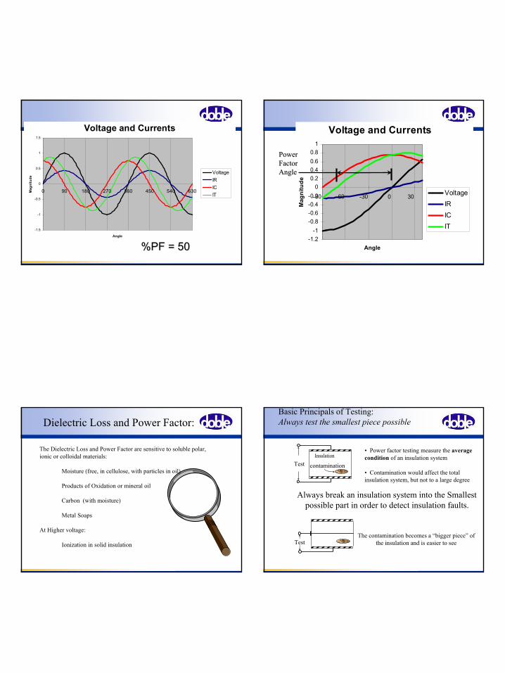
%PF = 50%PF = 50
Voltage and Currents
-1.2-1
-0.8-0.6-0.4-0.2
00.20.40.60.8
1
-90 -60 -30 0 30
Angle
Mag
nitu
de
VoltageIRICIT
PowerPowerFactorFactorAngleAngle
Dielectric Loss and Power Factor:
The Dielectric Loss and Power Factor are sensitive to soluble polar,ionic or colloidal materials:
Moisture (free, in cellulose, with particles in oil)
Products of Oxidation or mineral oil
Carbon (with moisture)
Metal Soaps
At Higher voltage:
Ionization in solid insulation
Basic Principals of Testing:Always test the smallest piece possible
TestInsulation
contamination
• Power factor testing measure the average condition of an insulation system
• Contamination would affect the total insulation system, but not to a large degree
Always break an insulation system into the Smallest possible part in order to detect insulation faults.
TestThe contamination becomes a “bigger piece” of
the insulation and is easier to see
15
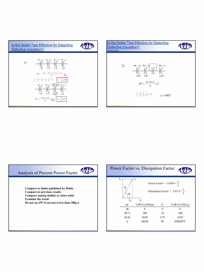
P F∑
= =. . .5 5 5 + + + .54
.5
1 12
12
12
12
2c
= + + + = c p F=12
PF = .5
2 pF
PF = .5 PF = .5 PF = .5
2 pF 2 pF 2 pF
PF x∑
= + =. . .5 3 2 54
1 0 c pF= 12
PF = .5
2 pF
PF = .5 PF =2.5 PF = .5
2 pF 2 pF 2 pF
1)
Is the Doble Test Effective for Detecting Defective Insulation?
PF = .5
2 pF
PF = .5 PF = .5
2 pF 2 pF
PF =+ +
=. . . .5 5 5
35
1 12
12
12
15c
= + + = . c =.667
2)
Is the Doble Test Effective for Detecting Defective Insulation? (continued)
Analysis of Percent Power Factor
Compare to limits published by DobleCompare to previous resultsCompare among similar or sister unitsExamine the trendDo not use PF if current is less than 300µA
Power Factor vs. Dissipation Factor
E
Θ
δ
IR
IC IT
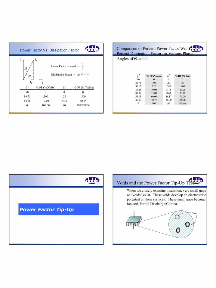
Power Factor = = II
Dissipation Factor = = II
R
T
R
C
COS
TAN
Θ
δ
Θ° % PF (% COS Θ) δ° % DF (% TAN ∆)90 0 0 0
89.71 .500 .29 .50084.26 10.00 5.74 10.05
0 100.00 90 INFINITY
16
= II
R
T
orPower Fact = cos θ
R
C
= II
Dissipation Factor = tan δ
90 0 0 0θθ ° % PF (% COS ) δ° % DF (% TAN ∆)
89.71 .500 .29 .50084.26 10.00 5.74 10.05
0 100.00 90 INFINITY
Power Factor Vs. Dissipation Factor
E
θ
δ
IR
IC IT
θ % PF (% cos) δ % DF (% tan)90 0 0 0
89.71 .50 .29 .5087.13 5.00 2.87 5.0084.26 10.00 5.74 10.0581.37 15.00 8.63 15.1853.13 60.00 36.87 75.0045.00 70.71 45.00 100.00
0 100 90 infinity
Comparison of Percent Power Factor With Percent Dissipation Factor for Various Phase Angles of Θ and δ
Power Factor Tip-Up
Voids and the Power Factor Tip-Up TestWhen we closely examine insulation, very small gaps or “voids” exist. These voids develop an electrostatic potential on their surfaces. These small gaps become ionized: Partial Discharge/Corona.
Voids
17
Partial Discharge (Corona)
•The phenomenon of an electrical discharge that does not completely bridge the insulation between electrodes or conductors.
Corona -- accompanied by a faint glowPartial Discharge -- may not be luminous (preferred term)
•Partial discharge occurs in:
A void within an insulation system where the voltage gradient is sufficiently high -- has a damaging effect on surrounding materials.
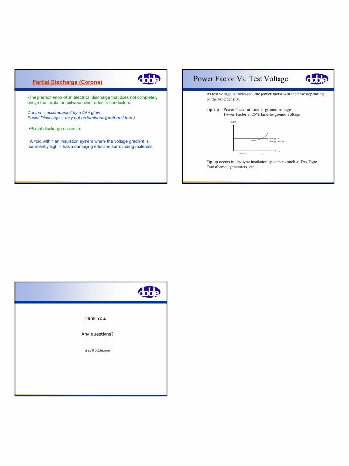
Power Factor Vs. Test Voltage
As test voltage is increased, the power factor will increase dependingon the void density.
Tip-Up = Power Factor at Line-to-ground voltage -Power Factor at 25% Line-to-ground voltage
25% L-G L-GE
%PF
%PF @ 25% L-G%PF @ L-G
Tip-up occurs in dry-type insulation specimens such as Dry Type Transformer, generators, etc.….
Thank You.
Any questions?

![[1914] Edmund Burke - Of the Sublime and Beautiful -- New York, P.F. Collier & Son Company](https://img.pdfslide.us/doc/110x75/577cd8b11a28ab9e78a1c4b1/1914-edmund-burke-of-the-sublime-and-beautiful-new-york-pf-collier.jpg)