Embed Size (px)
DESCRIPTION
petroleum
Citation preview

CAPE-OPENDelivering the power of component software
and open standard interfacesin Computer-Aided Process Engineering
Open Interface Specification:Petroleum Fractions Interface
www.colan.org

2
ARCHIVAL INFORMATION
Filename Petroleum Fractions Interface Specification.doc
Authors CO-LaN consortium
Status Public
Date August 2003
Version version 2
Number of pages 40
Versioning version 2, reviewed by Jean-Pierre Belaud, August 2003
version 1, October 2001
Additional material
Web location www.colan.org
Implementationspecifications version
CAPE-OPENv1-0-0.idl (CORBA)
CAPE-OPENv1-0-0.zip and CAPE-OPENv1-0-0.tlb (COM)
Comments
3
IMPORTANT NOTICES
Disclaimer of Warranty
CO-LaN documents and publications include software in the form of sample code. Any such softwaredescribed or provided by CO-LaN --- in whatever form --- is provided "as-is" without warranty of any kind.CO-LaN and its partners and suppliers disclaim any warranties including without limitation an impliedwarrant or fitness for a particular purpose. The entire risk arising out of the use or performance of anysample code --- or any other software described by the CAPE-OPEN Laboratories Network --- remains withyou.
Copyright © 2003 CO-LaN and/or suppliers. All rights are reserved unless specifically stated otherwise.
CO-LaN is a non for profit organization established under French law of 1901.
Trademark Usage
Many of the designations used by manufacturers and seller to distinguish their products are claimed astrademarks. Where those designations appear in CO-LaN publications, and the authors are aware of atrademark claim, the designations have been printed in caps or initial caps.
Microsoft, Microsoft Word, Visual Basic, Visual Basic for Applications, Internet Explorer, Windows andWindows NT are registered trademarks and ActiveX is a trademark of Microsoft Corporation.
Netscape Navigator is a registered trademark of Netscape Corporation.
Adobe Acrobat is a registered trademark of Adobe Corporation.

4
SUMMARY
This document proposes interfaces for handling complex mixtures of the type of petroleum fractions. Thedocument contains requirements expressed in textual form, as well as Use Cases. From these requirementsthe corresponding interfaces where developed.
The scope of the interfaces, initially conceived as for handling Petroleum Fractions and Assays, was reducedto only Petroleum Fractions, since this was considered the most crucial and value added part of theinterfaces.
The proposed interfaces allow UNIT Operation clients to access properties specific of the petroleum industrysuch as e.g. cloud point, pour point, Reid vapor pressure, and also to perform run-time re-characterisation ofthe properties of hypothetical components representing a petroleum fraction (e.g. Normal Boiling Point,Molecular Weight, Specific Gravity, Critical Temperature, etc).
This allows extending plug-and-play of UNIT operation components to the specific operations present in thepetroleum and gas industry (e.g. refining, upstream, etc). In particular, these interfaces will allow plug-and-play of refinery reactor operations. These operations present a characteristic problematic, that requires aspecial treatment, as it is described in this document.

5
ACKNOWLEDGEMENTS
6
CONTENTS
1. INTRODUCTION....................................................................................................................................................8
1.1 PROPERTIES........................................................................................................................................................81.1.1 Petroleum Basic Properties ..........................................................................................................................81.1.2 Special Petroleum Properties........................................................................................................................9
1.2 FLOWSHEET SIMULATION...................................................................................................................................91.2.1 Common ........................................................................................................................................................91.2.2 Oil Refining ...................................................................................................................................................9
2. REQUIREMENTS .................................................................................................................................................12
2.1 TEXTUAL REQUIREMENTS.................................................................................................................................122.1.1 Summary of requirements and new interfaces for petroleum assay and fractions ......................................132.1.2 Summary of requirements that will be fulfilled with the proposed interfaces .............................................14
2.2 USES CASES ......................................................................................................................................................152.2.1 Actors ..........................................................................................................................................................152.2.2 List of Use Cases.........................................................................................................................................152.2.3 Use Cases Maps ..........................................................................................................................................162.2.4 Use Cases ....................................................................................................................................................16
2.3 SEQUENCE DIAGRAMS......................................................................................................................................21
3. ANALYSIS AND DESIGN....................................................................................................................................22
3.1 OVERVIEW .......................................................................................................................................................223.2 SEQUENCE DIAGRAMS ......................................................................................................................................223.3 INTERFACE DIAGRAMS......................................................................................................................................223.4 STATE DIAGRAMS.............................................................................................................................................223.5 OTHER DIAGRAMS ............................................................................................................................................223.6 INTERFACES DESCRIPTION ...............................................................................................................................23
3.6.1 ICapeThermoPetroFractions ......................................................................................................................233.6.2 ICapeUnitTypeInfo......................................................................................................................................28
3.7 SCENARIOS – PROPOSED SCENARIO TO VALIDATE THE INTERFACES................................................................293.7.1 Introduction.................................................................................................................................................293.7.2 Validation Scenario.....................................................................................................................................30
4. INTERFACE SPECIFICATIONS........................................................................................................................32
4.1 COM IDL ........................................................................................................................................................324.2 CORBA IDL....................................................................................................................................................32
5. NOTES ON THE INTERFACE SPECIFICATIONS.........................................................................................33
5.1 REQUIREMENTS FROM OTHER COMPONENTS ....................................................................................................335.2 LIST OF PETROLEUM FRACTION/S PROPERTIES .................................................................................................33
5.2.1 Set of Fractions ...........................................................................................................................................335.2.2 Individual Fractions....................................................................................................................................35
6. PROTOTYPES IMPLEMENTATION................................................................................................................37
7. SPECIFIC GLOSSARY TERMS .........................................................................................................................38
8. BIBLIOGRAPHY ..................................................................................................................................................39
8.1 PROCESS SIMULATION REFERENCES..................................................................................................................398.2 COMPUTING REFERENCES.................................................................................................................................398.3 GENERAL REFERENCES.....................................................................................................................................39
9. APPENDICES ........................................................................................................................................................40

7
LIST OF FIGURES
FIGURE 1 USE-CASES MAP.................................................................................................................................................16FIGURE 2 MAIN SEQUENCE DIAGRAM ................................................................................................................................21FIGURE 3 INTERFACE DIAGRAM .........................................................................................................................................22
8
1. Introduction
For chemically well-defined fluids, such as petrochemicals, simulators conveniently draw on large databanks of chemical compounds for essential property data whereas for petroleum, a material of indefinitecomposition, such a direct means of representation is not practical. However, the large number ofhydrocarbon compounds that constitute oil behave ‘approximately’ as ideal fluids, thus making the’lumping’ of 100’s of real compounds into 10’s of hypothetical compounds an adequate simplifyingassumption for many (but not all) process engineering purposes (see later).
Although predominately a hydrocarbon fluid, there are contaminants present in both fossil and synthetic oils,especially the former e.g. sulphur, metals, inert gases and water/brine. These have a significant impact onseparation and reaction processes. For instance, the sulphur treating and handling aspect of refining entailmany reactors and separations. And, small amounts of metals affect adversely the catalyst activity in theconversion processes.
1.1 Properties
1.1.1 Petroleum Basic Properties
A detailed analysis of crude oil, by compound, up to carbon number 6 is usually obtainable and the C6+remainder is characterised by “pseudo-components”. Occasionally a complete analysis is known up to C11.Rarely, but occasionally, a ‘full’ compositional analysis undertaken; in this case mass spectrometry couldidentify families, at least, of compounds. Such resolution can be important to lubricants manufacture inparticular. The more usual characterization procedure is to measure the boiling range distribution of crude oilas the cumulative amount distilled versus temperature and then to splice the resulting S-shaped curve into anumber of histogram-type intervals, each one representing a pseudo component which is a hypotheticalhydrocarbon of certain normal boiling point and containing an amount of material determined by the splicingregime. The boiling temperature of a pseudo-component is the volumetric average temperature for theparticular histogram interval. A corresponding curve can be measured for density distribution. Typically,even the best laboratory instruments, chromatograph or distillation apparatus, cannot measure boiling pointsmuch above 550C, yet a significant fraction of crude oil boils at higher temperatures and the final boilingpoint is uncertain. This introduces a complicating factor for characterization, and the ‘end point’ is assumedto be 800+C.
The basic properties (normal boiling point, density, molecular weight) of light hydrocarbons are essentiallythose of the pure compounds. For heavier hydrocarbons, characterised by pseudo-components, the boilingpoint and density are obtained as described above and molecular weight is predicted as a function of thesetwo properties. Other correlation variants on the inter-relationships between those three properties exist aswell. From these properties component criticals and acentric factor can be determined and thus the dataneeded by an EOS (equation of state) thermodynamic model is furnished. For the heavier end of the boilingrange there is uncertainty associated with molecular weight since any attempt to measure high boilers inconventional apparatus would result in their thermal decomposition. For this reason vapour pressure typethermodynamic methods are sometimes used to predict K-values for refinery separations involving suchmaterial, as opposed to customary EOS methods. Vapour pressure can be correlated from basic physicalproperties and is supported by measurement. In high pressure oil production applications the uncertainty inthe component criticals is taken as justification for using them as tuning parameters to reproduce fieldGas/Oil ratios (i.e.VLE or VLLE).
To conclude, the manner by which hydrocarbon feedstock is characterised so as to be recognisable toflowsheeting packages makes a unique demand not only on the properties handling aspect of a simulator butalso on how feed flowrate is specified i.e. in terms of whole oil (bulk substance) rather than directly in termsof individual constituent pseudo-component flowrates. The characterization procedure outlined aboveassigns an appropriate amount of the ‘whole’ to each pseudo-component.

9
1.1.2 Special Petroleum Properties
In addition to the basic physical properties of density, molecular weight, and so on, which are essential tophase equilibrium calculations, a wide range of other properties are key quality and control indicators inpractice. For refined products these include, sulphur content, flash point, Reid vapour pressure, cloud point,freeze point, refractive index, nickel content, vanadium content, Conradson carbon and toxicity parameters.The properties referred to as ‘special’, here, are variously known as refinery properties, petroleum properties,qualities, cold properties and inspection properties: there are standard procedures for their measurement andthey are reported in a typical oil assay. Such properties are not predictable, either from basic physicalproperties or from molecular structure. Any one pseudo-component will comprise many different compounds(paraffins, naphthenes, olefins and aromatics). If sufficient data points are available to form a curve(covering the boiling range) for a given property such as sulphur content, values can be assigned to eachpseudo in a manner analogous to the boiling curves already described. The value of any given petroleumproperty for a flowsheet stream is determined according to an empirical mixing rule applied to all of thecontributions from the various pseudo components in that stream. Several of the properties mentioned abovedemand mixing rules which are very non-linear in form and are frequently proprietary.
These properties are tracked throughout processes for a variety of reasons e.g. cloud point may be a controlpoint for a distillation product streams, metals content which are catalyst poisons is required by reactormodels and other properties such as sulphur and cetane number must be known for product quality control.
1.2 Flowsheet Simulation
1.2.1 Common
For distillation, at least, of crude oil, thermodynamic representation is straightforward even though thecharacterization of the material is not straightforward. For instance, several feeds each represented by a C6+fraction may be present in any one simulation e.g. if a number of different oils are present. As a consequencethere could be more than one pseudo-component of identical boiling point but differing in all otherproperties, most particularly density. By convention each pseudo-component has an invented name whichcontains the normal boiling point number for easy recognition e.g. NBP-120. Clearly, if a component list hastwo or more pseudos with the same boiling point and different properties, the system has to manage thateventuality; producing unique names may be one approach. Procedures for mathematically combining oils oroil fractions into a single blend of consolidated boiling curve, density curve and so on, with a consequentbreakdown into a single set of pseudos is common practice. Significantly, this step is performed beforesolving the flowsheet proper. However, if the requirement is to retain in a flowsheet the identity of eachconstituent oil then there seems no simple way around characterising each one separately and introducing asmany corresponding sets of pseudos as there are oils to the simulation. This is entirely achievable incommercial simulators today but at a price which challenges practicality. The number of components in thecomponent list would run to many hundreds or even thousands (for a refinery), which adversely affects, at aminimum, the run time performance.
A component list must be capable of dealing with the entire oil, or oil blend, as a single ‘macro component’as far as defining total flowrate is concerned, yet must also break this down into pseudo-components.
1.2.2 Oil Refining
Distillation is adequately modelled using the pseudo-component approach for the characterization of oilblends or oil fractions. However, pseudo-components pose difficulties for modelling extraction and certainreaction processes. Component distribution coefficients describing a liquid-liquid extraction process wouldmost commonly be determined by a liquid activity model. But, activity coefficients for pseudo-componentsof unknown molecular structure are indeterminate. For reaction processes too, pseudo-components have theirlimitations: formal reactions cannot be expressed, elemental balance may be compromised and heat ofreaction is not readily predictable since heat of formation is uncertain.
10
The modelling of refinery reactors is relatively straightforward for light-ends processes and relativelycomplex for heavy-ends processes. Reactors which deal with light feeds (C6-), which include alkylation,isomerisation, MTBE, Catalytic polymerisation processes and so on can be approached in the same way asfor any other chemical process. Property data of the actual compounds is available from data banks, thereactions are known, the stoichiometry is known and the kinetics/equilibrium are generally well known.Simulator architectures cater for this general requirement already, even if the specification of proprietarykinetics is simulator-specific.
Catalytic Reforming processes handle slightly heavier feeds (naphtha) but, as earlier, the chemistry is wellknown. Typically, xx components and yy reactions might be required. The challenge for this type of reactionmodel is that the upstream simulated feed to the reactor may be characterised by pseudo-components (plusParaffinic Olefinic Naphthenic Aromatic breakdown) so a way is needed to ‘map’ the boiling curve onto thexx components. These components may be internal to the reactor UO and not appear elsewhere in theflowsheet.
Refinery conversion processes convert high boiling material into more valuable light products such asgasoline and diesel, and for these the chemistry is complex and fundamental models are a rarity. There aretwo categories of conversion process: catalytic and thermal. Fluidised catalytic cracking (FCC),hydrocracking and residue cracking are of the catalytic type whereas visbreaking and coking are thermal-type. Either way, a semi-empirical approach is common combining limited theory with plant data to producestatistical models employing tuning factors. One such factor may account for catalyst de-activation, forinstance. Commercial software for these reactor types does exist for the individual units; theirimplementation in flowsheet simulation is rare.
Purification processes, e.g. de-sulphurisation, treat the particular hydrocarbon fraction with gaseoushydrogen at elevated pressure, over catalyst, and the particular process may be vapour-phase or two-phase.These are kinetic processes for which semi-empirical methods are usually adopted.
The common thread in the fore-mentioned processes is that feed to a conversion or purification unit will be,in flowsheeting terms, a stream comprising pseudo-components. Possibilities, of varying acceptability, fordefining the product streams for the particular reactor model include:
• Inlet is described by a given set of pseudo-component properties; outlet is determinedthe same pseudo-component properties. The amount of material in each pseudo in theeffluent is determined by the reactor algorithm. Since these processes are known tochange both the basic and the petroleum properties of the material, the effluentproperties assigned to the outlet stream will be inaccurate. For instance, across avisbreaker, or even a milder reactor such as a hydrotreater, there is only a slight shift inboiling range from inlet to outlet but the accompanying shift in density curve is marked.
• Inlet is described by a given set of pseudo-component properties; outlet is described bya different set of pseudo-component properties. A severe limitation of most conventionalcommercial simulators is that a second set of pseudos, which will carry the effluent,must be defined a priori (before the simulation starts) and, being of fixed properties, willnot change with reactor operating conditions. The simulator carries both sets of pseudosthroughout the flowsheet. The reactor algorithm ‘fills’ the second set of pseudos perhapsby applying fixed yields (derived from plant measurement). The combined componentlist is obviously much longer than for the previous scenario, even though there may bealmost complete overlap between the two sets of pseudos as a consequence of a smallshift in boiling range between inlet and outlet. This is computationally inefficient as itaffects the solution time for all other unit operations in the flowsheet.
• Inlet is described by a given set of pseudo-component properties; outlet is determined bythe same pseudo-component properties and internally the reactor model ‘maps’ pseudosto real chemical compounds. In this instance the reactor model applies a formalchemistry to the reaction. The real chemical compounds could be purely internal to the

11
reactor model. The effluent stream can easily be constituted back into pseudocomponents for feeding downstream processes.
• Inlet is described by a given set of pseudo-component properties; outlet is determined bythe ‘dynamically’ revised pseudo-component properties. This represents an idealwhereby all properties of each pseudo-component (basic and petroleum), other thanboiling point, are updated by the reactor algorithm. Such a solution introduces theconcept of stream-dependent component properties.

12
2. Requirements
2.1 Textual requirements
Petroleum fractions are generated from petroleum assay. Petroleum assay data are generally available instandard form such as ASTM D86 or True Boiling Point (TBP) analysis. The data are in the form of percentboiled off versus temperature. Given these data and other information such as bulk specific gravity (orcurve), and bulk molecular weight (or curve), petroleum fractions can be generated. Each petroleum fractionwill have assigned to it a molecular weight, specific gravity and boiling temperature. From these basic data,other characterization parameters and properties such as critical properties (TC, PC, VC, ZC), ideal gas heatcapacity, vapor pressure, and liquid viscosity can be estimated from industry standard correlation such as theLee-Kesler or Riazi-Daubert methods. In general, these characterization parameters and properties do notchange in the course of the simulation. From the property-model point of view, petroleum fractions are thesame as real components, such as methane or water. Note that the methods used to estimate thesecharacterization parameters can be traced using the reporting functions of the Property System.
There is another class of properties associated with petroleum assay: curves of properties such as Reid vaporpressure, carbon content, viscosity, various metal contents, cloud point, and so on. The curves of propertiesare normally given as a function of percent boiled off or temperature. Each curve property for a givenpetroleum assay can be broken down (sliced) in the same way as the Assay D86 or TBP data; with a propertyvalue associated with a corresponding petroleum fraction. These properties, if not changed during the courseof the calculations, are not any different from the characterization parameters TC, PC, etc discussed in theprevious paragraph.
However, these properties assigned to a petroleum fraction can change during the flowsheet calculations,when, for example, the components undergo chemical reactions in a reactor block. The sulfur contents maybe changed in a desulfurization unit. In fact, a reactor model can also alter the molecular weight or specificgravity of a given petroleum fraction. As a result, the petroleum fraction will also need to be re-characterized. (Note that when the petroleum fraction is re-characterized, the methods used to estimate theproperty and parameters of the fraction will not be changed).
When the characterization parameters and petroleum properties of a petroleum fraction are changed, thepetroleum fraction essentially becomes a new species (component). In other words, the reactor generates anew set of petroleum fractions. The characterization parameters and curve properties of these new fractionsmust be determined. If the reactor is within a recycle loop, properties of these fractions must be continuallyupdated.
It is evident that new interfaces are required to update characterization parameters and curve properties forpetroleum fractions.
The CAPE-OPEN material template contains the component (species) information. To handle petroleumassay and fraction, the material template should be extended to include assay and fractions. To allowtracking of petroleum properties as the petroleum fractions go through the flowsheet from one Units modelto another (and may change in the Reactor model), the material template should be extended to include thepetroleum properties as attributes.
Another problem related to assays and petroleum fractions is one of lumping and de-lumping. It iscomputationally expensive to deal with a large number of components. In petroleum refining, it is notunusual to have 50 to 100 petroleum fractions. It is desirable to reduce the number of components withoutsacrificing the calculation accuracy. There are available methods to lump petroleum fractions into a smallerset of fractions and vice versa. Interfaces are required for these features.

13
2.1.1 Summary of requirements and new interfaces for petroleum assay and fractions
• R1. New properties such as Reid vapor pressure, cloud point. Define the complete listof properties.
• R2. Material Template extension to include component type to allow handling ofassays and petroleum fractions.
o Define the list of component types: real neutral component, ions, assay,petroleum fraction, polymer, etc.
• R3. Material Template extension to include petroleum properties as attributes.
• R4. New Interface to re-characterize pseudo component parameters.
o Method for number of petroleum components.
o Method for updating characterization parameters for a given set of petroleumcomponents
• R5. New Interface to update petroleum properties.
o Method for number of petroleum properties.
o Method for number of petroleum components and real components.
o Method for updating petroleum property.
o Method for copying petroleum property
• R6. New Interface to lump petroleum fractions into smaller set of fractions (includingthe corresponding characterization parameters and curve properties)
• R7. Interface to de-lump petroleum fractions into its original set of fractions.
14
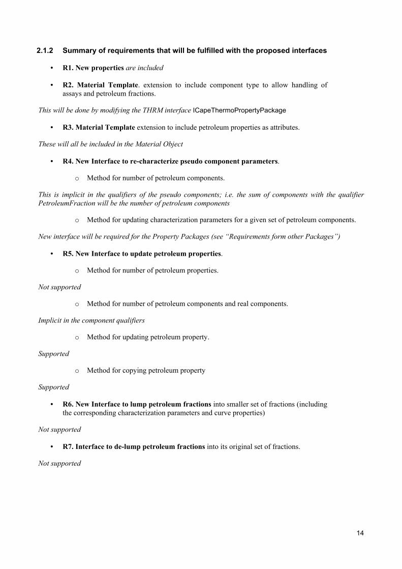
2.1.2 Summary of requirements that will be fulfilled with the proposed interfaces
• R1. New properties are included
• R2. Material Template. extension to include component type to allow handling ofassays and petroleum fractions.
This will be done by modifying the THRM interface ICapeThermoPropertyPackage
• R3. Material Template extension to include petroleum properties as attributes.
These will all be included in the Material Object
• R4. New Interface to re-characterize pseudo component parameters.
o Method for number of petroleum components.
This is implicit in the qualifiers of the pseudo components; i.e. the sum of components with the qualifierPetroleumFraction will be the number of petroleum components
o Method for updating characterization parameters for a given set of petroleum components.
New interface will be required for the Property Packages (see “Requirements form other Packages”)
• R5. New Interface to update petroleum properties.
o Method for number of petroleum properties.
Not supported
o Method for number of petroleum components and real components.
Implicit in the component qualifiers
o Method for updating petroleum property.
Supported
o Method for copying petroleum property
Supported
• R6. New Interface to lump petroleum fractions into smaller set of fractions (includingthe corresponding characterization parameters and curve properties)
Not supported
• R7. Interface to de-lump petroleum fractions into its original set of fractions.
Not supported

15
2.2 Uses cases
2.2.1 Actors
Flowsheet Builder. The person who sets up the flowsheet, the structure of the flowsheet,chooses thermo models and the unit operation models that are in the flowsheet. This personhands over a working flowsheet to the Flowsheet User The Flowsheet Builder can act as aFlowsheet User.
Simulator Executive. The part of a simulator whose job it is to create, or load, a previouslystored flowsheet, solve it and display the results.
Refinery UNIT (REF-UNIT). A CAPE-OPEN Unit Operation requiring petroleumfractions recharacterization procedures. These are typically reactor operations andblenders/mixers.
2.2.2 List of Use Cases
UC-001 Add REF-UNIT to Flowsheet
UC-002 Specify REF UNIT´s Material Connections
UC-003 REF-UNIT Gets Petro Props from Inlet Material Connections
UC-004 REF-UNITs Sets Petro Props in Outlet Material Connections.
UC-005 REF-UNIT Defines Outlet Material Objects from Inlet Material Objects.
UC-006 Evaluate REF-UNIT.

16
2.2.3 Use Cases Maps
COSE
Add REF UNIT ToFlowsheet
Specify REF UNITMaterial Connections
UNIT
Evaluate REF UNIT
FlowsheetBuilder
REF UNIT Gets PetroProps From Inlet
Material Connections
REF UNIT Sets PetroProps In Outlet Material
Connections
REF UNIT DefinesOutlet Material Objects
From Inlet MaterialObjects
Figure 1 Use-Cases map
2.2.4 Use Cases
UC-001 ADD REF-UNIT TO FLOWSHEET
Actors: Flowsheet Builder
Priority: As in UNIT Use Case Add UNIT to Flowsheet
Classification:
Context:
Pre-conditions: As in UNIT Use Case Add UNIT to Flowsheet
Flow of events:
As in UNIT Use Case Add UNIT to Flowsheet, but the UNIT is a Refinery UNIT.
And:
The Simulator Executive asks the UNIT is it is a Refinery UNIT (i.e. requires petroleum fraction properties)
If so, the Simulator Executive will ask the UNIT if it requires re-characterization of petroleum fraction properties (seenote below).
17
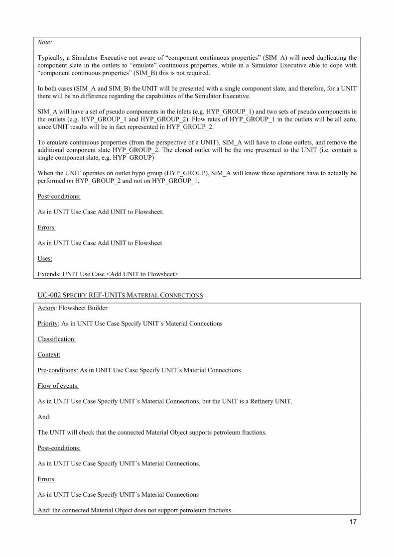
Note:
Typically, a Simulator Executive not aware of “component continuous properties” (SIM_A) will need duplicating thecomponent slate in the outlets to “emulate” continuous properties, while in a Simulator Executive able to cope with“component continuous properties” (SIM_B) this is not required.
In both cases (SIM_A and SIM_B) the UNIT will be presented with a single component slate, and therefore, for a UNITthere will be no difference regarding the capabilities of the Simulator Executive.
SIM_A will have a set of pseudo components in the inlets (e.g. HYP_GROUP_1) and two sets of pseudo components inthe outlets (e.g. HYP_GROUP_1 and HYP_GROUP_2). Flow rates of HYP_GROUP_1 in the outlets will be all zero,since UNIT results will be in fact represented in HYP_GROUP_2.
To emulate continuous properties (from the perspective of a UNIT), SIM_A will have to clone outlets, and remove theadditional component slate HYP_GROUP_2. The cloned outlet will be the one presented to the UNIT (i.e. contain asingle component slate, e.g. HYP_GROUP)
When the UNIT operates on outlet hypo group (HYP_GROUP), SIM_A will know these operations have to actually beperformed on HYP_GROUP_2 and not on HYP_GROUP_1.
Post-conditions:
As in UNIT Use Case Add UNIT to Flowsheet.
Errors:
As in UNIT Use Case Add UNIT to Flowsheet
Uses:
Extends: UNIT Use Case <Add UNIT to Flowsheet>
UC-002 SPECIFY REF-UNITS MATERIAL CONNECTIONS
Actors: Flowsheet Builder
Priority: As in UNIT Use Case Specify UNIT´s Material Connections
Classification:
Context:
Pre-conditions: As in UNIT Use Case Specify UNIT´s Material Connections
Flow of events:
As in UNIT Use Case Specify UNIT´s Material Connections, but the UNIT is a Refinery UNIT.
And:
The UNIT will check that the connected Material Object supports petroleum fractions.
Post-conditions:
As in UNIT Use Case Specify UNIT´s Material Connections.
Errors:
As in UNIT Use Case Specify UNIT´s Material Connections
And: the connected Material Object does not support petroleum fractions.

18
Uses:
Extends: UNIT Use Case <Specify UNIT´s Material Connections>
UC- 003 REF-UNIT GETS PETRO PROPS FROM INLET MATERIAL CONNECTIONS
Actors: REF UNIT
Priority: High
Classification:
Context:
Pre-conditions:
The UNIT has indicated to the Simulator Executive that it is a REF UNIT. Thus the Simulator Executive can prepare itsMaterial Objects appropriatelly.
Flow of events:
As in the UNIT Use Case <Get Input Material Streams From Input Ports>, but the information to gather is nowconcerning Petroleum Fractions, thus:
The UNIT connects with the part of its inlet Material Object that carries Petroleum Fraction properties
The UNIT requests certain “PetroFrac” properties. These properties can correspond to:
A) A particular “PetroFrac” pseudo component (e.g. molecular weight, density, NBP, etc), in which case the UNIT willsupply the identifiers of the components whose properties are to be retrieved.
B) The whole PetroFracs (e.g. single properties such as PourPoint, FlashPoint, etc, or curve properties such asTBPCurve)
Post-conditions:
The UNIT is delivered with the requested property.
Errors:
The property does not exist as specified by the REF UNIT
Uses:
Extends: UNIT Use Case <Get Input Material Streams From Input Ports>
UC- 004 REF-UNIT SETS PETRO PROPS IN OUTLET MATERIAL CONNECTIONS
Actors: REF UNIT
Priority: High
Classification:
Context:
Pre-conditions:
The UNIT has indicated to the Simulator Executive that it is a REF UNIT. Thus the Simulator Executive can prepare itsMaterial Objects appropriately.
19
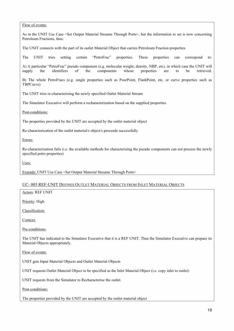
Flow of events:
As in the UNIT Use Case <Set Output Material Streams Through Ports>, but the information to set is now concerningPetroleum Fractions, thus:
The UNIT connects with the part of its outlet Material Object that carries Petroleum Fraction properties
The UNIT tries setting certain “PetroFrac” properties. These properties can correspond to:
A) A particular “PetroFrac” pseudo component (e.g. molecular weight, density, NBP, etc), in which case the UNIT willsupply the identifiers of the components whose properties are to be retrieved.
B) The whole PetroFracs (e.g. single properties such as PourPoint, FlashPoint, etc, or curve properties such asTBPCurve)
The UNIT tries re-characterising the newly specified Outlet Material Stream
The Simulator Executive will perform a recharacterization based on the supplied properties.
Post-conditions:
The properties provided by the UNIT are accepted by the outlet material object
Re-characterication of the outlet material/s object/s proceeds successfully
Errors:
Re-characterization fails (i.e. the available methods for characterising the pseudo components can not process the newlyspecified petro properties)
Uses:
Extends: UNIT Use Case <Set Output Material Streams Through Ports>
UC- 005 REF-UNIT DEFINES OUTLET MATERIAL OBJECTS FROM INLET MATERIAL OBJECTS
Actors: REF UNIT
Priority: High
Classification:
Context:
Pre-conditions:
The UNIT has indicated to the Simulator Executive that it is a REF UNIT. Thus the Simulator Executive can prepare itsMaterial Objects appropriately.
Flow of events:
UNIT gets Input Material Objects and Outlet Material Objects
UNIT requests Outlet Material Object to be specified as the Inlet Material Object (i.e. copy inlet to outlet)
UNIT requests from the Simulator to Recharacterise the outlet.
Post-conditions:
The properties provided by the UNIT are accepted by the outlet material object
20
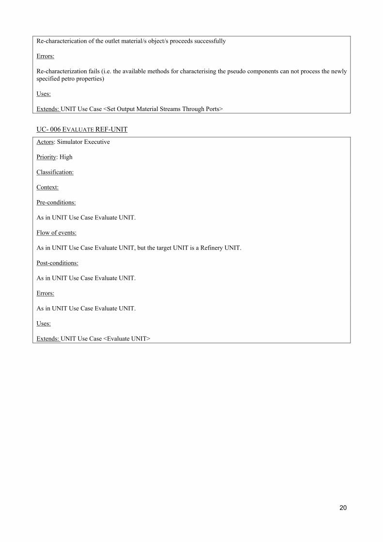
Re-characterication of the outlet material/s object/s proceeds successfully
Errors:
Re-characterization fails (i.e. the available methods for characterising the pseudo components can not process the newlyspecified petro properties)
Uses:
Extends: UNIT Use Case <Set Output Material Streams Through Ports>
UC- 006 EVALUATE REF-UNIT
Actors: Simulator Executive
Priority: High
Classification:
Context:
Pre-conditions:
As in UNIT Use Case Evaluate UNIT.
Flow of events:
As in UNIT Use Case Evaluate UNIT, but the target UNIT is a Refinery UNIT.
Post-conditions:
As in UNIT Use Case Evaluate UNIT.
Errors:
As in UNIT Use Case Evaluate UNIT.
Uses:
Extends: UNIT Use Case <Evaluate UNIT>
21
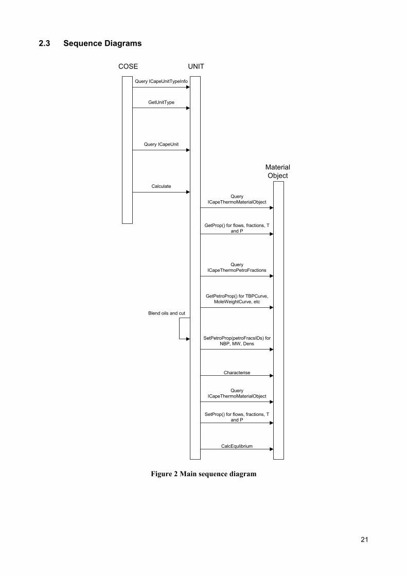
2.3 Sequence Diagrams
COSE UNIT
MaterialObject
Query ICapeUnitTypeInfo
GetUnitType
Query ICapeUnit
Calculate
QueryICapeThermoMaterialObject
GetProp() for flows, fractions, Tand P
QueryICapeThermoPetroFractions
GetPetroProp() for TBPCurve,MoleWeightCurve, etc
Blend oils and cut
SetPetroProp(petroFracsIDs) forNBP, MW, Dens
Characterise
QueryICapeThermoMaterialObject
SetProp() for flows, fractions, Tand P
CalcEqulibrium
Figure 2 Main sequence diagram

22
3. Analysis and Design
3.1 Overview
3.2 Sequence diagrams
3.3 Interface diagrams
The interface ICapeThermoPetroFractions will be implemented on the Material Object, as the interfaceICapeThermoMaterialObject is, and will serve for Refinery Unit Operation to access petroleum fractionproperties.
IN-001 INTERFACE DIAGRAM
<<Interface>>ICapeThermoPetroFractions
SetPetroPropGetPetroProp
RemovePetroPropCharacterize
DefineFromPetroFractions
<<Interface>>ICapeThermoMaterialObject
<<Interface>>ICapeUnitTypeInfo
GetUnitType
<<Interface>>ICapeUnit
Figure 3 Interface diagram
The interface ICapeUnitTypeInfo will be implemented on the UNIT and will give the Simulator Executiveinformation on the type of Unit Operations; more specifically the simulator will need to know if theoperation is a refinery reactor, an oil blender, other refinery operation different from the first two, or anyother regular unit operation.
Although the interface ICapeUnitTypeInfo is specifically defined for the Simulator to know that a refineryoperation has been inserted in the flowsheet, this interface can be used to provide a classification of any typeof Unit Operation.
3.4 State diagrams
3.5 Other diagrams
INCORPORER
23
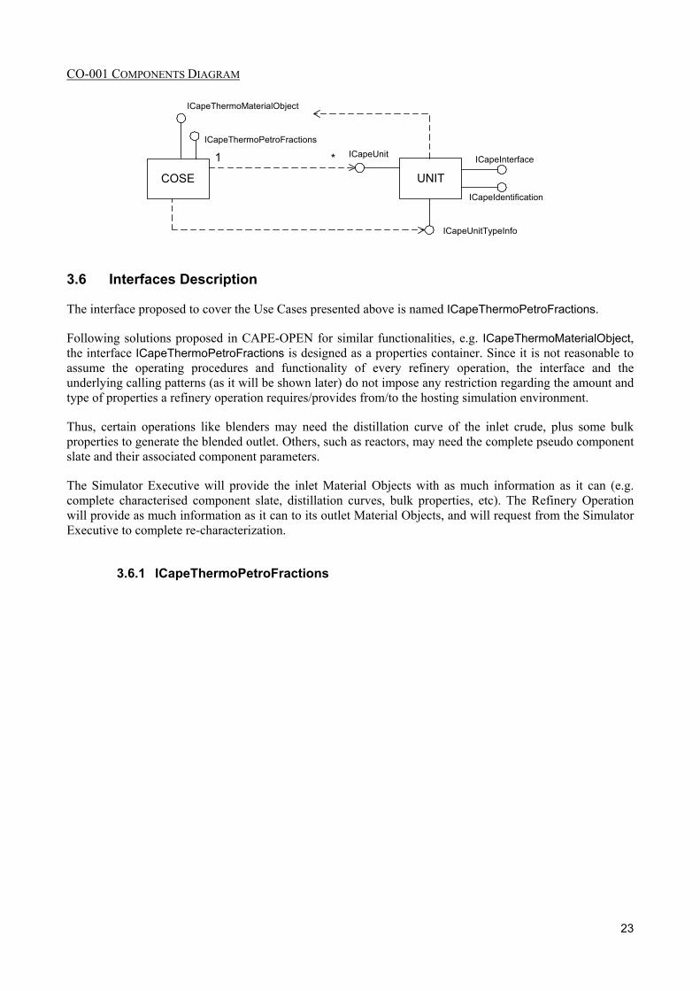
CO-001 COMPONENTS DIAGRAM
COSE UNITICapeInterface
ICapeIdentification
ICapeUnit1 *
ICapeThermoMaterialObject
ICapeThermoPetroFractions
ICapeUnitTypeInfo
3.6 Interfaces Description
The interface proposed to cover the Use Cases presented above is named ICapeThermoPetroFractions.
Following solutions proposed in CAPE-OPEN for similar functionalities, e.g. ICapeThermoMaterialObject,the interface ICapeThermoPetroFractions is designed as a properties container. Since it is not reasonable toassume the operating procedures and functionality of every refinery operation, the interface and theunderlying calling patterns (as it will be shown later) do not impose any restriction regarding the amount andtype of properties a refinery operation requires/provides from/to the hosting simulation environment.
Thus, certain operations like blenders may need the distillation curve of the inlet crude, plus some bulkproperties to generate the blended outlet. Others, such as reactors, may need the complete pseudo componentslate and their associated component parameters.
The Simulator Executive will provide the inlet Material Objects with as much information as it can (e.g.complete characterised component slate, distillation curves, bulk properties, etc). The Refinery Operationwill provide as much information as it can to its outlet Material Objects, and will request from the SimulatorExecutive to complete re-characterization.
3.6.1 ICapeThermoPetroFractions
24
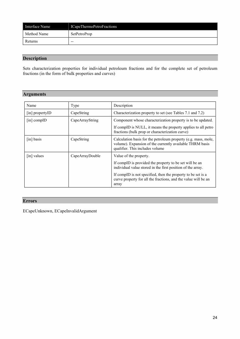
Interface Name ICapeThermoPetroFractions
Method Name SetPetroProp
Returns --
Description
Sets characterization properties for individual petroleum fractions and for the complete set of petroleumfractions (in the form of bulk properties and curves)
Arguments
Name Type Description
[in] propertyID CapeString Characterization property to set (see Tables 7.1 and 7.2)
[in] compID CapeArrayString Component whose characterization property is to be updated.
If compID is NULL, it means the property applies to all petrofractions (bulk prop or characterization curve)
[in] basis CapeString Calculation basis for the petroleum property (e.g. mass, mole,volume). Expansion of the currently available THRM basisqualifier. This includes volume
[in] values CapeArrayDouble Value of the property.
If compID is provided the property to be set will be anindividual value stored in the first position of the array.
If compID is not specified, then the property to be set is acurve property for all the fractions, and the value will be anarray
Errors
ECapeUnknown, ECapeInvalidArgument
25
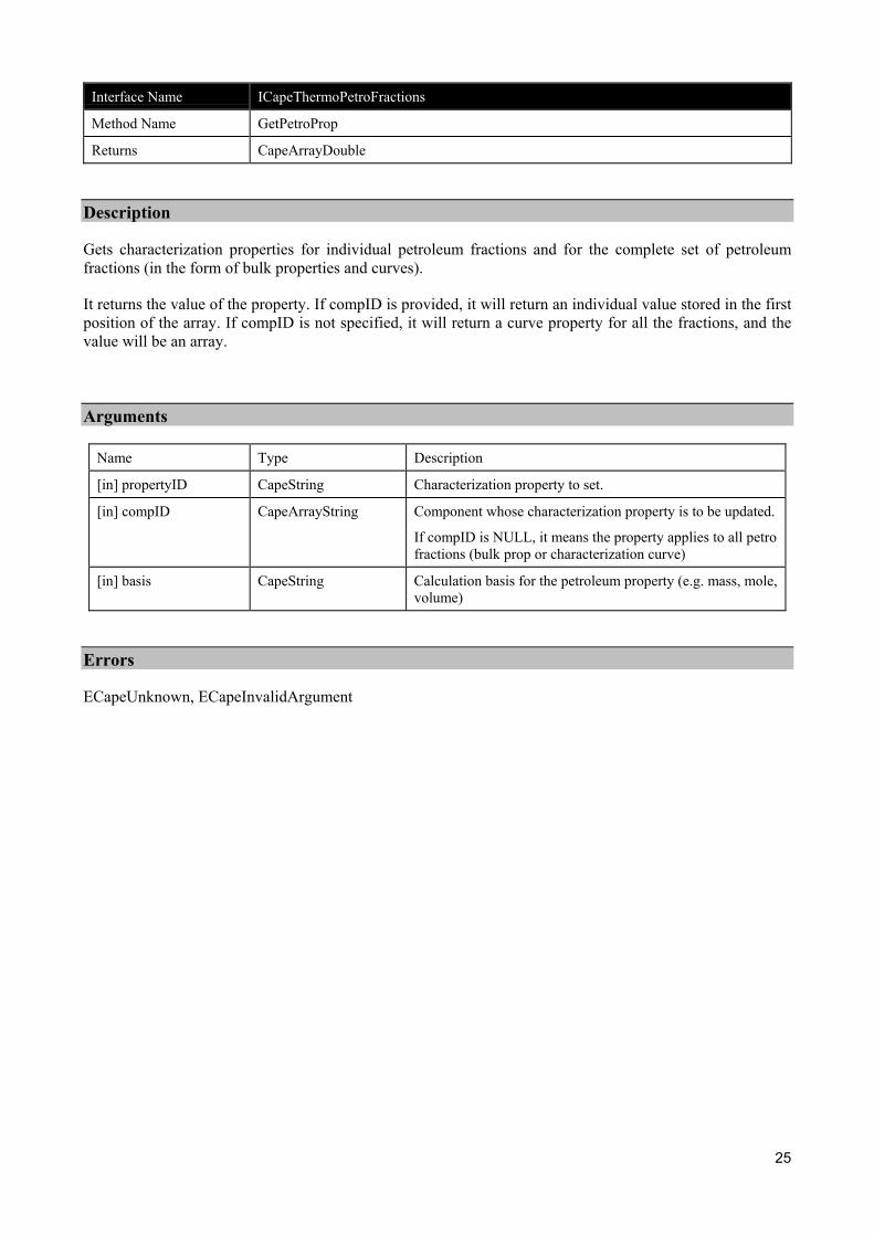
Interface Name ICapeThermoPetroFractions
Method Name GetPetroProp
Returns CapeArrayDouble
Description
Gets characterization properties for individual petroleum fractions and for the complete set of petroleumfractions (in the form of bulk properties and curves).
It returns the value of the property. If compID is provided, it will return an individual value stored in the firstposition of the array. If compID is not specified, it will return a curve property for all the fractions, and thevalue will be an array.
Arguments
Name Type Description
[in] propertyID CapeString Characterization property to set.
[in] compID CapeArrayString Component whose characterization property is to be updated.
If compID is NULL, it means the property applies to all petrofractions (bulk prop or characterization curve)
[in] basis CapeString Calculation basis for the petroleum property (e.g. mass, mole,volume)
Errors
ECapeUnknown, ECapeInvalidArgument
26
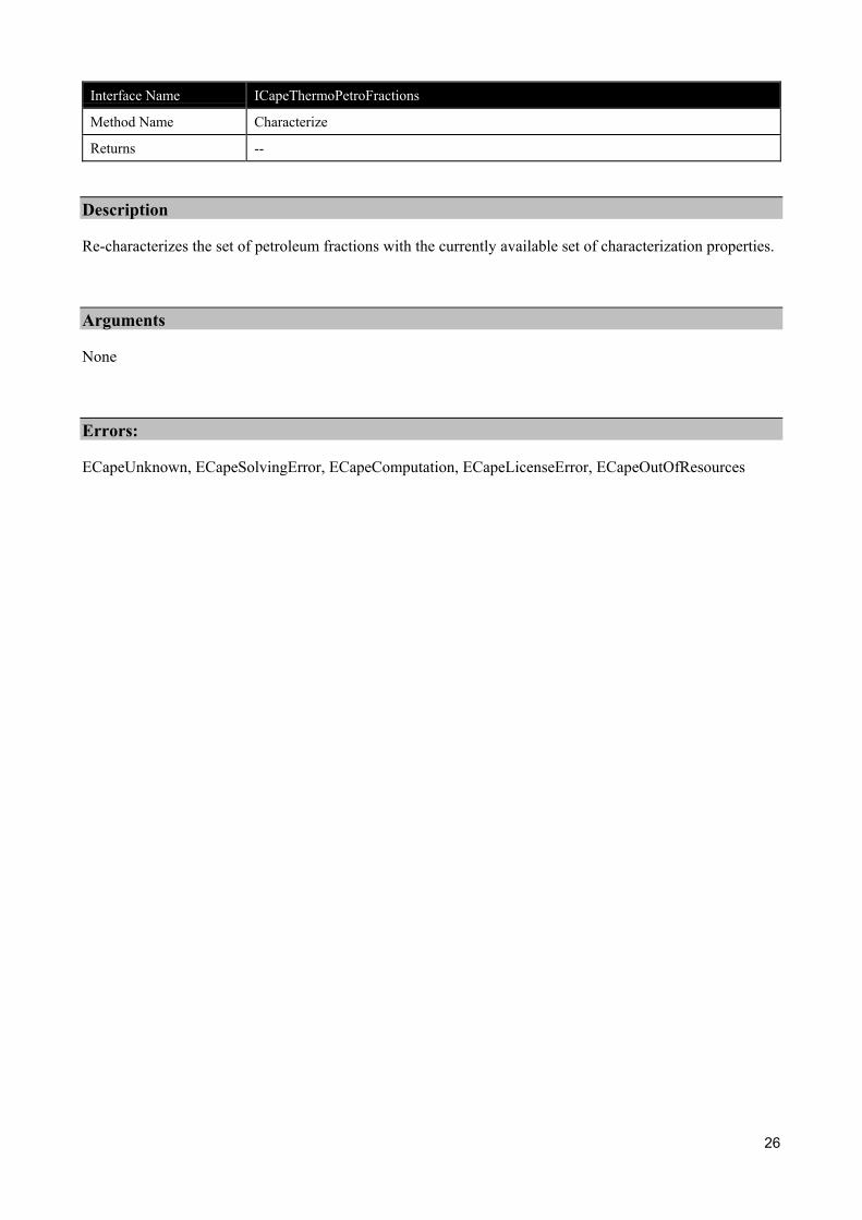
Interface Name ICapeThermoPetroFractions
Method Name Characterize
Returns --
Description
Re-characterizes the set of petroleum fractions with the currently available set of characterization properties.
Arguments
None
Errors:
ECapeUnknown, ECapeSolvingError, ECapeComputation, ECapeLicenseError, ECapeOutOfResources
27
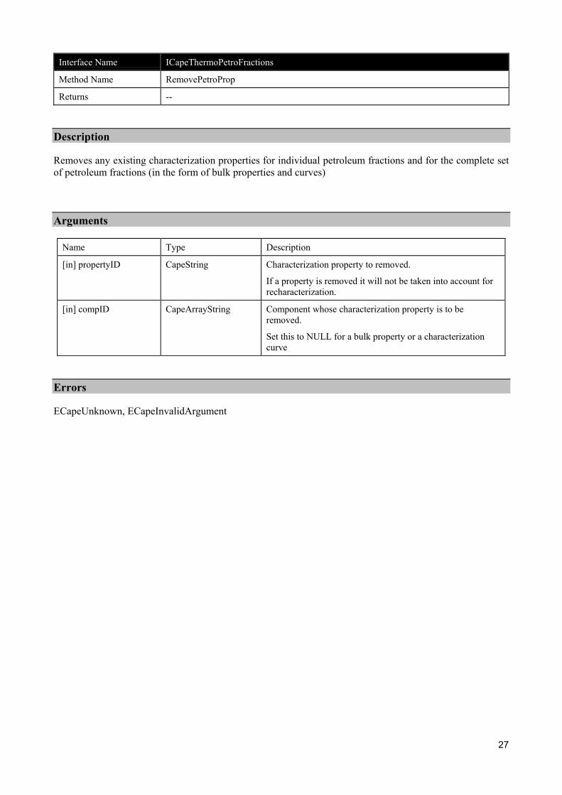
Interface Name ICapeThermoPetroFractions
Method Name RemovePetroProp
Returns --
Description
Removes any existing characterization properties for individual petroleum fractions and for the complete setof petroleum fractions (in the form of bulk properties and curves)
Arguments
Name Type Description
[in] propertyID CapeString Characterization property to removed.
If a property is removed it will not be taken into account forrecharacterization.
[in] compID CapeArrayString Component whose characterization property is to beremoved.
Set this to NULL for a bulk property or a characterizationcurve
Errors
ECapeUnknown, ECapeInvalidArgument
28
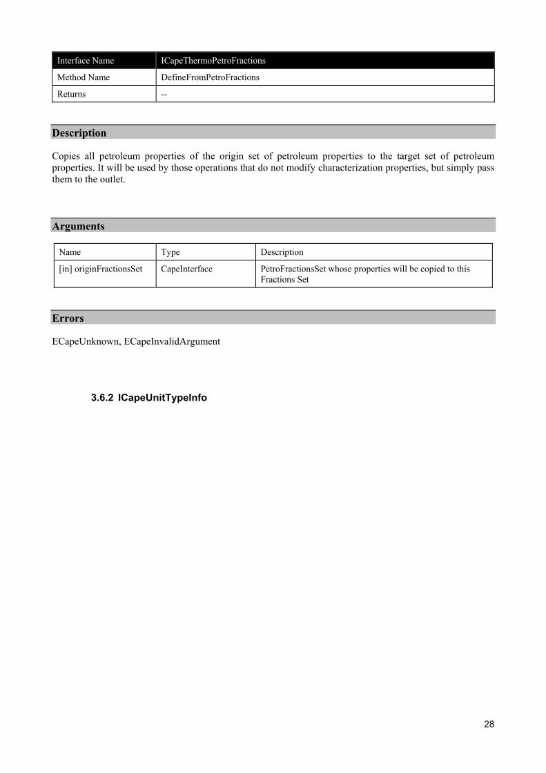
Interface Name ICapeThermoPetroFractions
Method Name DefineFromPetroFractions
Returns --
Description
Copies all petroleum properties of the origin set of petroleum properties to the target set of petroleumproperties. It will be used by those operations that do not modify characterization properties, but simply passthem to the outlet.
Arguments
Name Type Description
[in] originFractionsSet CapeInterface PetroFractionsSet whose properties will be copied to thisFractions Set
Errors
ECapeUnknown, ECapeInvalidArgument
3.6.2 ICapeUnitTypeInfo

29
Interface Name ICapeUnitTypeInfo
Method Name GetUnitType
Returns CapeUnitType
Description
Gets the type of Unit Operation. Among others, the following types should be defined:
CapeUnitType:
CAPE_REFINERYREACTOROP,
CAPE_REFINERYBLENDEROP,
CAPE_REFINERYGENERALOP,
CAPE_CONVENTIONALOP
Arguments
None
Errors
ECapeUnknown, ECapeInvalidArgument
3.7 Scenarios – Proposed Scenario to Validate the Interfaces
3.7.1 Introduction
As described in this document, the proposed interfaces support the operations of refinery units, by exposing aseries of properties, characteristics of the oil industry. In this sense, the new interfaces increase the containercapabilities of the Material Object.
In addition to this, the new interfaces propose a complete new behavior (i.e. re-characterization of pseudocomponents), that affects the functionality required from CAPE-OPEN property packages.
Thus, to support continuous updating of component properties (which is something that e.g. refinery reactorsand blenders will require), a CAPE-OPEN property package, if applied to the flowsheet, has to allow itscomponents properties to be updated during the course of the simulation. This implies modifying the set ofinterfaces for Thermo Property Package, and consequently enhancing the existing prototypes.
Since, from a realistic viewpoint, this will not be achievable within the remaining project period, theproposed validation scenario assumes that no CAPE-OPEN property package is applied to the flowsheet.Rather, native simulator property package will be used.
This simplification of the project does not compromise or modifies the testing of the proposed interfaces.Thus, to test the ICapeThermoPetroFractions and ICapeUnitTypeInfo interfaces, the only requirements are:1) to have a UNIT plug, that will act as a client of ICapeThermoPetroFractions, and 2) to modify the
30
implementation of the Material Object to support the new interface and to provide the UNIT plug with therequired petroleum properties.
The UNIT plug will need to be able to estimate pseudo component properties, but this will be achieved usingsimulator native characterization methods.
Although the proposed interfaces allow plugging refinery UNIT components into Simulators aware orunaware of continuous properties, the prototype will be demonstrated in a non-continuous propertiessimulator (e.g. HYSYS.Process).
3.7.2 Validation Scenario
The proposed prototype is an oil blender. The oil blender will accept two inlet material objects, eachrepresenting a distinct crude oil, and will produce a blended oil.
Oils in each one of the inlet MOs will be represented by a set of pseudo components (e.g. Oil_1 isrepresented by HypGrp_1 and Oil_2 is represented by HypGrp_2). The blended oil will be represented by athird group of pseudo components (e.g. HypGrp_3).
Each oil will carry its own cold properties, curves and component characterization parameters. These will bestored in the corresponding MOs.
The Blender Prototype will fetch the following information from the inlets:
Accessing the ICapeThermoMaterialObject interface:
Number of light-end components and their corresponding molar fractions/flows
Temperature and pressure
Pure Component properties such as Molecular weight and liquid density
Accessing the ICapeThermoPetroFractions interface:
TBPCurve for the two inlets
CutPointCurve for the two inlets
MassDensityCurve for the two inlets
MoleWeightCurve for the two inlets
With this information, the blender operation will characterize a new oil based on a user specified number ofcuts (i.e. pseudo components). This new set of pseudos will be stored as part of Hypo_Group_3
The blender will provide the following information on its single outlet:
Through the ICapeThermoPetroFractions interface:
Normal Boiling point of each new pseudo component
Molecular weight of each new pseudo component
Density of each new pseudo component
Once this information has been provided, the blender will request from the outlet material object tocharacterize the new set of pseudo components.

31
The Simulator Executive will then use the specified component properties to estimate e.g. Tc, Pc, AcentricFactor, etc. The Simulator Executive will use its own characterization methods to determine thesecomponent properties.
Through the ICapeThermoMaterialObject interface the blender will then provide the followinginformation:
Mole Fractions of each new pseudo component
Total molar flow rate of the blended oil
Temperature and pressure
And will request from the Material Object to perform a flash operation, to complete calculations.

32
4. Interface Specifications
4.1 COM IDL
// You can get these intructions in PetroleumFractions.idl file from CAPE-OPENv1-0-0.zip
4.2 CORBA IDL
// You can get these intructions in CAPE-OPENv1-0-0.idl within theCAPEOPEN100::Business::PhyProp::Thrm::Cose module and inCAPEOPEN100::Business::UnitOp::Unit module
33
5. Notes on the interface specifications
5.1 Requirements from other components
In order that reactor unit operations can work inside a COSE implementing the describedICapeThermoPetroFractions interface, it must be possible that a property package allowsrecharacterization of the pseudo component properties.
Therefore a new method (or better a new interface, e.g. ISupportRecharacterization) is required to updatecomponent properties like molecular weight, density, normal boiling point etc…
In addition, if the property package is provided with its own routines to characterize pseudo-components, thismethod will allow activating those routines.
A new basis qualifier should be added to the THRM specification, this is “volume”. Thus,properties such as “Olefins”, “Paraffins” etc, can be obtained/get in volumetric basis, whichis often required in refinery operations.
The ICapeThermoPropertyPackage::GetComponentList method should be updated toinclude a new component qualifier; this is the component type. Thus, Regular,PetroleumFraction, etc, will be valid component qualifiers.
5.2 List of Petroleum Fraction/s properties
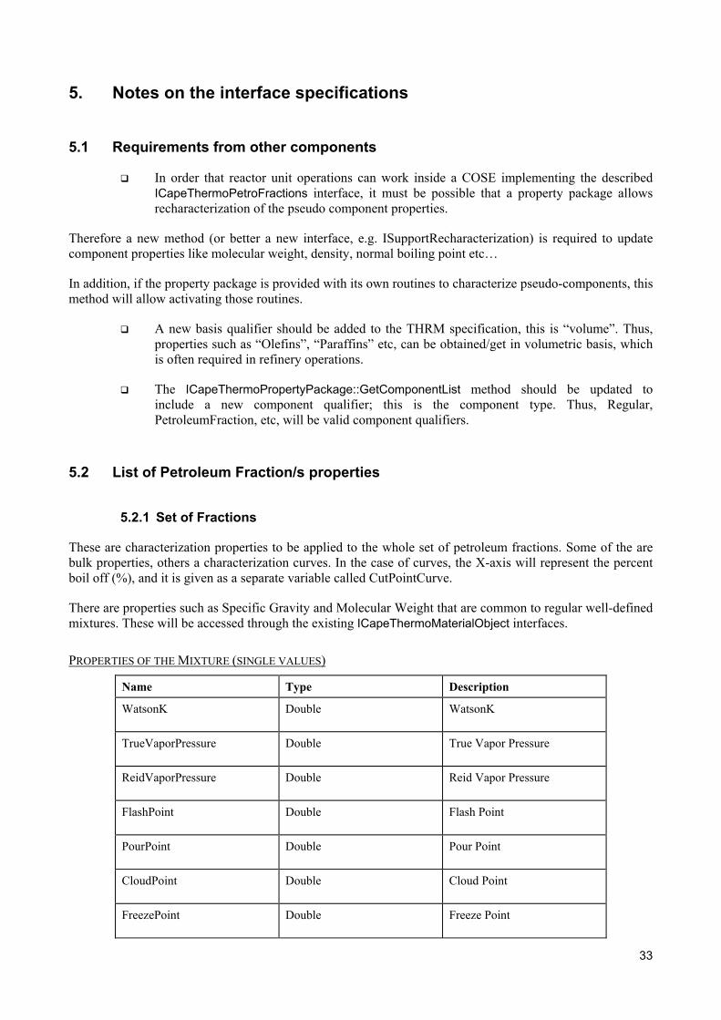
5.2.1 Set of Fractions
These are characterization properties to be applied to the whole set of petroleum fractions. Some of the arebulk properties, others a characterization curves. In the case of curves, the X-axis will represent the percentboil off (%), and it is given as a separate variable called CutPointCurve.
There are properties such as Specific Gravity and Molecular Weight that are common to regular well-definedmixtures. These will be accessed through the existing ICapeThermoMaterialObject interfaces.
PROPERTIES OF THE MIXTURE (SINGLE VALUES)
Name Type Description
WatsonK Double WatsonK
TrueVaporPressure Double True Vapor Pressure
ReidVaporPressure Double Reid Vapor Pressure
FlashPoint Double Flash Point
PourPoint Double Pour Point
CloudPoint Double Cloud Point
FreezePoint Double Freeze Point
34
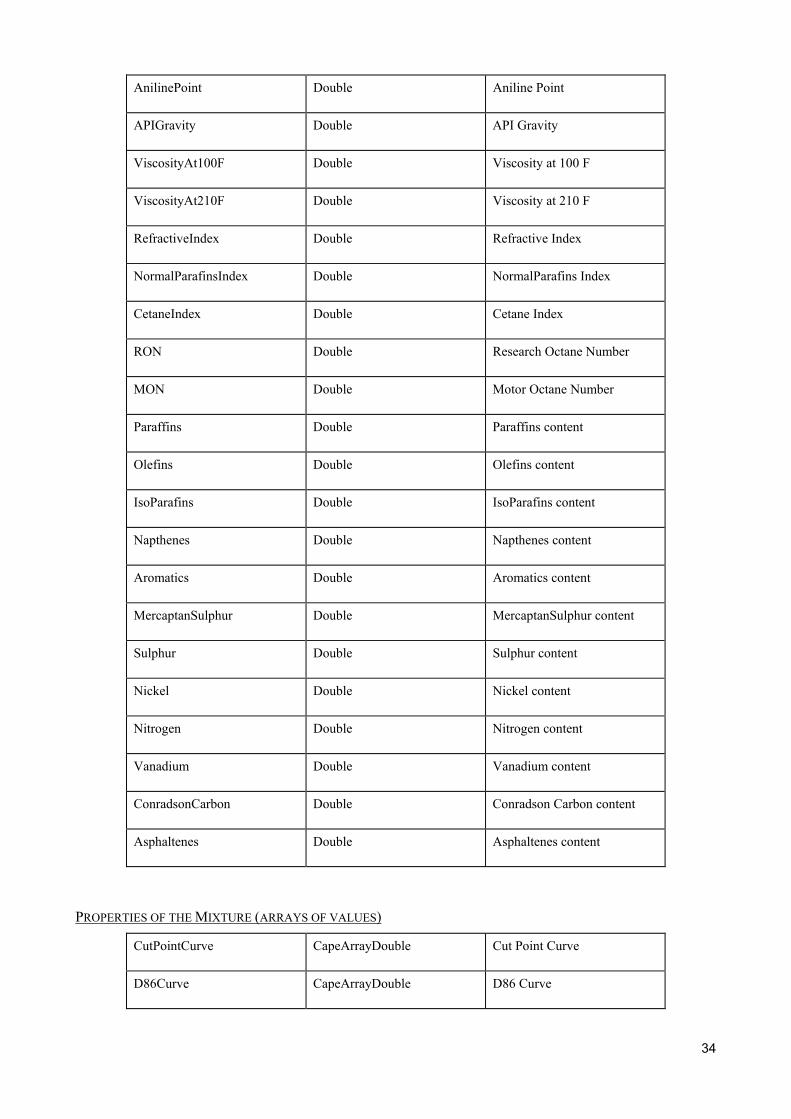
AnilinePoint Double Aniline Point
APIGravity Double API Gravity
ViscosityAt100F Double Viscosity at 100 F
ViscosityAt210F Double Viscosity at 210 F
RefractiveIndex Double Refractive Index
NormalParafinsIndex Double NormalParafins Index
CetaneIndex Double Cetane Index
RON Double Research Octane Number
MON Double Motor Octane Number
Paraffins Double Paraffins content
Olefins Double Olefins content
IsoParafins Double IsoParafins content
Napthenes Double Napthenes content
Aromatics Double Aromatics content
MercaptanSulphur Double MercaptanSulphur content
Sulphur Double Sulphur content
Nickel Double Nickel content
Nitrogen Double Nitrogen content
Vanadium Double Vanadium content
ConradsonCarbon Double Conradson Carbon content
Asphaltenes Double Asphaltenes content
PROPERTIES OF THE MIXTURE (ARRAYS OF VALUES)
CutPointCurve CapeArrayDouble Cut Point Curve
D86Curve CapeArrayDouble D86 Curve
35
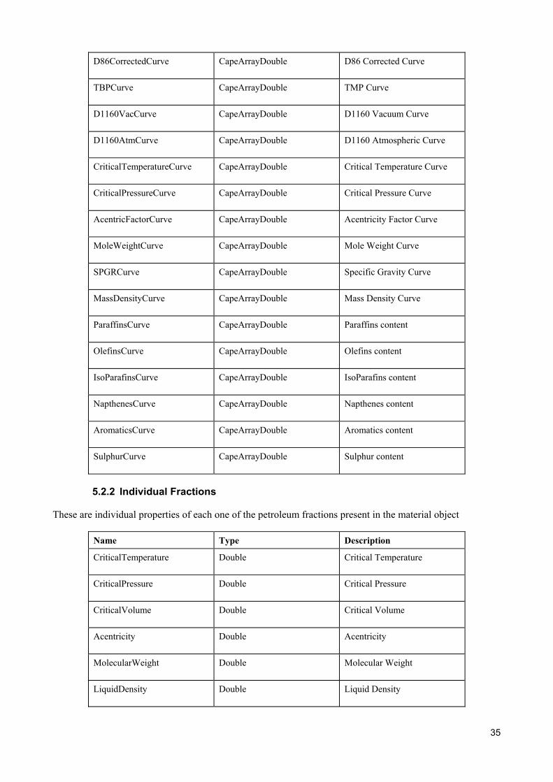
D86CorrectedCurve CapeArrayDouble D86 Corrected Curve
TBPCurve CapeArrayDouble TMP Curve
D1160VacCurve CapeArrayDouble D1160 Vacuum Curve
D1160AtmCurve CapeArrayDouble D1160 Atmospheric Curve
CriticalTemperatureCurve CapeArrayDouble Critical Temperature Curve
CriticalPressureCurve CapeArrayDouble Critical Pressure Curve
AcentricFactorCurve CapeArrayDouble Acentricity Factor Curve
MoleWeightCurve CapeArrayDouble Mole Weight Curve
SPGRCurve CapeArrayDouble Specific Gravity Curve
MassDensityCurve CapeArrayDouble Mass Density Curve
ParaffinsCurve CapeArrayDouble Paraffins content
OlefinsCurve CapeArrayDouble Olefins content
IsoParafinsCurve CapeArrayDouble IsoParafins content
NapthenesCurve CapeArrayDouble Napthenes content
AromaticsCurve CapeArrayDouble Aromatics content
SulphurCurve CapeArrayDouble Sulphur content
5.2.2 Individual Fractions
These are individual properties of each one of the petroleum fractions present in the material object
Name Type Description
CriticalTemperature Double Critical Temperature
CriticalPressure Double Critical Pressure
CriticalVolume Double Critical Volume
Acentricity Double Acentricity
MolecularWeight Double Molecular Weight
LiquidDensity Double Liquid Density

36
NormalBoilingPoint Double Normal Boiling Point

37
6. Prototypes implementation

38
7. Specific Glossary Terms

39
8. Bibliography
8.1 Process simulation references
8.2 Computing references
8.3 General references

40
9. Appendices