Embed Size (px)
Citation preview

48
MOTORISED THROTTLE BODIES
RENAULT Mégane II petrol versions use the Sagem 3000 injection system. This is adevelopment of the Sagem 2000 injection system used in RENAULT Laguna II.
As with the earlier system, the Sagem 3000 injection system manages engine torqueby means of a motorised throttle. However, the motorised throttle technology differsaccording to the engine fitted.
X84p
1MOT
-P07
02O1
P002
6
PETROL ENGINESPETROL ENGINES

50
K4M and F4R ENGINES
• Operation
The 1.6 16 V and 2.0 16 V engines also use a VDO motorised throttle body.
However, on these engines the computer controls a DC motor to open the butterflyvalve. The movement of the electric motor is transmitted to the butterfly by a gear train.
The motor is controlled by an open modulated pulse current (OCR).
The computer reverses the polarities to change the direction of rotation and thus openor close the butterfly valve.
A double cross gradient potentiometer informs the computer of the position of thebutterfly.
X84p
1MOT
-p07
02O1
P000
2
3
1
2
500 µs/Div
20.0
15.0
10.0
5.0
0.0 V
- 5.0
- 10.0
- 15.0
- 20.0
1 Electric DC motor. 2 Return spring.3 Injection computer.

51
• Replacement of the throttle bodiesThe programming of the butterfly stops is performed only once in their lifetime.
After connecting a new throttle body, programming of the stops is performed when theignition is turned on for the first time. Subsequently the computer stores these values.
MECHANICAL FEATURES OF THE K4M ENGINE +
A CAMSHAFT PHASER TO OPTIMISE TORQUE
In order to improve cylinder mixture filling at all engine speeds, the K4M + engine isfitted with a WT inlet camshaft phaser (Variable Valve Timing).
1 Camshaft phaser.
X84p
1MOT
-p07
02O1
P000
3
1

52
Delaying the moment of inlet valve closure optimises the cylinder mixture capacityaccording to engine speed. This enhances torque at medium speed and power at highspeed.
At high speed (C), leaving the inlet valves open longer allows extended mixtureadmission due to its high speed.
By contrast, at lower speeds (A), the gas inertia is low. It is therefore preferable to closethe inlet valves earlier to prevent poor filling of the cylinders and a loss of torque due toreverse flow of cool gases.
The more the speed increases, the more the inlet valve closure must be delayed (B).
On the K4M + engine, the delay varies continuously from 0 to 45° crankshaft.
A B C X84p
1MOT
-p07
02O1
P000
4
High speedsMedium speedsLow speeds
Bottomdead
centre
X84p1
MOT-p07
02O1P
0005
• Operation and strategiesLubrication of the phaser is provided by a solenoidvalve located on the cylinder head. The variable OCRpower feed (12 volts, 250 hertz) allows the oil to bedistributed within the mechanism and thus modify thephase angle.

53
From 1 500 to 4 500 rpm, the computer supplies the solenoid valve with a variableOCR proportional to the desired delay.
Above 4 500 rpm, the solenoid valve is no longer powered. The position of themechanism enhances filling at high speed. In this position, a locking piston locks themechanism.
NOTE
Up to 1 500 rpm, the solenoid valve is not powered. The mechanism is lockedby the piston.
As soon as solenoid valve is powered (speed above 1 500 rpm), the pressure ofthe oil forces the locking piston back and releases the mechanism.
• A camshaft position sensor to check the angular phasing
Unlike the F4R and K4J engines, the K4M + engine has a position sensor on the inletcamshaft.
X84p
1MOT
-p07
02O1
P000
6
20 ms/Div
V
2 1 3 4

54
It is of the Hall effect type. The signal is obtained by earthing a potential of 12 voltssupplied by the injection computer.
This sensor is used for:
- injection and ignition phasing after starting (recognition of cylinder 1),- continuously measuring the position of the inlet camshaft to check the angular
offset value.
NOTE
On the F4R and K4J engines, the phasing is performed by software.
• Fault managementThe computer detects the following faults:
- electrical fault in the control solenoid valve,- phaser position or measurement error.
On detection of one of these faults, control of the phaser is inhibited.
A CAM FOLLOWER TO REDUCE LOAD ON THE BELT
X84p
1MOT
-p07
02O1
P000
7
The camshaft phaser on the K4M +engine allows a large variation in thetiming (45° crankshaft). This increasesloads on the timing belt.
The cam follower reduces these loads.
55
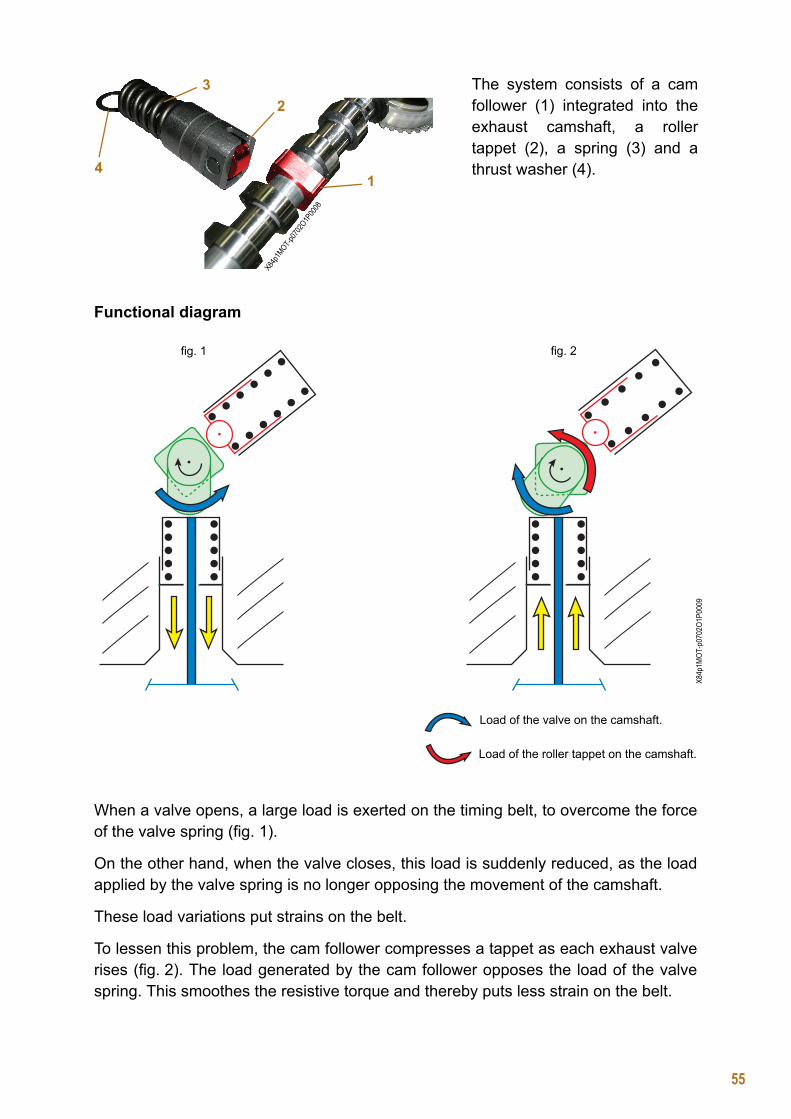
Functional diagram
When a valve opens, a large load is exerted on the timing belt, to overcome the forceof the valve spring (fig. 1).
On the other hand, when the valve closes, this load is suddenly reduced, as the loadapplied by the valve spring is no longer opposing the movement of the camshaft.
These load variations put strains on the belt.
To lessen this problem, the cam follower compresses a tappet as each exhaust valverises (fig. 2). The load generated by the cam follower opposes the load of the valvespring. This smoothes the resistive torque and thereby puts less strain on the belt.
The system consists of a camfollower (1) integrated into theexhaust camshaft, a rollertappet (2), a spring (3) and athrust washer (4).
X84p1
MOT-p07
02O1P
0008
1
23
4
X84p
1MOT
-p07
02O1
P000
9
Load of the valve on the camshaft.
Load of the roller tappet on the camshaft.
fig. 1 fig. 2

56
• Special notes on operations
EUROPEAN ONBOARD DIAGNOSIS: SOME CHANGES FROM THE SAGEM 2000 SYSTEM
REMINDERThe purpose of the EOBD function is to warn the driver by means of a warning lightwhen a fault in the injection system is likely to result in the exhaust exceeding emissioncontrol thresholds.
When the vehicle is in motion, the computer carries out the following tests:
- continuous monitoring of misfiring,- catalytic converter efficiency,- efficiency of the upstream oxygen sensor.
When removing the cylinderhead cover, do not removethe bolt (A).
This bolt prevents the tappetfrom coming out of itshousing when the camfollower is no longer pressingon it.
It is imperative to use theMOT 1669 tool to compressthe tappet during removaland refitting.
AX8
4p1M
OT-p
0702
O1P0
010
X84p1MOT-p0702O1P0011

57
FAULT FINDING FOR MISFIRING
A misfire is revealed by a fall in measured engine torque to below a predefinedthreshold.
A misfire rate of more than 15 % is considered destructive for the catalytic converter.The EOBD warning light flashes immediately to warn the driver that his catalyticconverter is in danger.
A misfire rate of less than 15 % is considered to cause pollution. In this case, the EOBDwarning light comes on permanently if the fault appears on three successive journeys.
For the misfire test to be operational, programming of the engine flywheel ring mustbe performed, there must be no electrical faults, and richness regulation must beactive.
The programming consists of learning the ring deformations. These deformations, dueto machining tolerances, cause variations in measured torque which can distortanalysis of misfires.
The programming must be repeated when replacing:
- an injection computer,- an engine flywheel ring,- an engine speed sensor.
After clearing, the programming is performed on the road.
To do this, two successive decelerations must be made in 3rd gear, from 4000 rpm topower takeup speed.
Misfiring results from poorquality combustion in one ormore cylinders.
It is detected by analysingengine torque motor via theflywheel wheel and itssensor. X8
4p1M
OT-p
0702
O1P0
012
Torque
Misfires detected
Detectionthreshold
t
IMPORTANT

58
NOTE
Compared with the Sagem 2000 injection system, the Sagem 3000 has thefollowing functions:- suppression of injection in the cylinders causing the misfires,- appearance of a fault indicating nonconformity of the engine flywheel ring.
If the deformation of the flywheel ring is too great, the computer cannot makesufficient correction for accurate detection of misfires.
FAULT FINDING FOR THE CATALYTIC CONVERTER
The ability of the catalytic converter to store oxygen indicates its condition.
As the catalytic converter ages, its ability to store oxygen diminishes, reducing its abilityto treat pollutant gases.
The catalytic converter test consists of varying the richness in order to send bursts ofoxygen into the catalytic converter. The computer then checks the signal from theupstream oxygen sensor. If the converter is damaged, it cannot store all the oxygenand rejects some of it; this causes the upstream sensor signal to fluctuate.
The efficiency test is performed once on the road, when the required conditions aresatisfied (speed stabilised at about 45 mph (70 km/h) for 1 to 2 minutes). If theamplitude of the upstream sensor signal is greater than a predefined threshold, thecomputer declares the converter to be faulty.
X84p
1MOT
-p07
02O1
P001
3
Storage capacity of the catalytic converter.
New catalytic converter Worn catalytic converter
Upstream oxygen sensor signal
Downstream oxygen sensor
signal
Upstream oxygen sensor signal
Downstream oxygen sensor
signal
Oxygen storage.

59
FAULT FINDING FOR THE OXYGEN SENSORS
The test of the upstream sensor is performed once on the road, when the requiredconditions are satisfied (speed stabilised at about 45 mph (70 km/h) for 1 to 2 minutes).
If the signal period of the upstream sensor signal is greater than a predefined threshold,the computer declares the converter to be faulty.
NOTE
The computer also performs an electrical test of the upstream and downstreamoxygen sensors.
X84p
1MOT
-p07
02O1
P001
4
Sensor in good condition.
Worn sensor.T2 > T1
T1
T2
V
t
Ageing of the oxygensensor is revealed bya slowdown in itsresponse time. Con-sequently, its cyclingperiod (T) increases.

60
AFTER-SALES STATIC TESTS
• Catalytic converterThe difference from the Sagem 2000 system is the possibility of performing a static testof the catalytic converter.
It is now possible to carry out the test in After-Sales using the diagnostic tool. Oncompletion of the test, the tool displays one of the following results:
- converter in good condition,- converter in fair condition,- converter in poor condition,- test not performed (impossible to obtain the test conditions).
A static test with a new converter may declare the component to be faulty.This is because the new converter needs a running in period (rise intemperature) before becoming efficient.
• Oxygen sensorAs with the catalytic converter, it is now possible to carry out a static test of thedownstream oxygen sensor using the diagnostic tool.
On completion of the test, the tool displays one of the following results:
- sensor in good condition,- sensor in fair condition,- sensor in poor condition,- test not performed (impossible to obtain the test conditions).
NOTE
The static tests are operational if:
- the ring programming has been carried out,- the richness programming has been carried out,- the injection system is in sequential operation,- double loop richness regulation is active,- there are no stored electrical faults.
WARNING

GLOSSARYAC Air conditioning
BFRH Passenger Compartment Relay and Fuse Box
CAN Control Area Network (multiplex communication protocol)
DAEV Electric variable power assisted steering
DF Terminal Digital Field ("available power" signal from an alternator)
EOBD European On Board Diagnosis
ESP Electronic Stability Program
ISO Diagnostic Fault finding via the K and L lines
PTC Positive Temperature Coefficient (electric heating resistor)
RCO Opening Cyclic Ratio signal (mass sequential time)
SSPP Tyre Pressure Monitor
UCH UCH
UPC Protection and Switching Unit
USB Universal Serial Bus (standard computer connection)
VSC Keyless vehicle
VVT Variable Valve Timing (variable distribution)

![Untitled-2 [petrol-is.org.tr]petrol-is.org.tr/sites/default/files/akademi.pdf · PROTOKOL TARAFLAR A-Petrol- i; Sendikasl Türkiye Petrol Kimya Lastik i;çileri Sendikast "PETROL-i$](https://img.pdfslide.us/doc/110x75/5e032b70d9e2ea2f204214f9/untitled-2-petrol-isorgtrpetrol-isorgtrsitesdefaultfiles-protokol-taraflar.jpg)