Embed Size (px)
Citation preview
POV Using LED’s
1 | P a g e
PERSISTANCE OF VISION USING LED’S
MSC PROJECT REPORT
M.S.Ramaiah Institute of Technology
Dept. of Electronics and Instrumentation Engineering
Submitted To
Dr.R.Elumalai
Professor & Head
Submitted By,
Rajat R Rokade – 1MS12IT039
Jishnu Gopal – 1MS12IT020
POV Using LED’s
2 | P a g e
CONTENTS
CERTIFICATE PAGE NO: 3
ACKNOWLEDGEMENT PAGE NO: 4
PROJECT ABSTRACT PAGE NO: 5
INTRODUCTION PAGE NO: 6
BLOCK DIAGRAM PAGE NO: 7 – 9
MECHANICAL ASSEMBLY PAGE NO: 10
CIRCUITARY PAGE NO: 11 – 15
SOFTWARE USED PAGE NO: 16
CODING PAGE NO: 17 – 18
PICTURES PAGE NO: 19 – 20
CONCLUSION PAGE NO: 21

POV Using LED’s
3 | P a g e
CERTIFICATE
We hereby certify that the work which is being presented in the MSC Project
report entitled “PERSISTANCE OF VISION USING LED’S” has been submitted to
the Department of Electronics and Instrumentation Engineering, M.S.Ramaiah
Institute of Technology, Bangalore, India is an authentic record of our own work
carried out during a period of November-2014 to December-2014 under the
supervision of Dr.R.Elumalai, Professor & Head, Electronics and Instrumentation
Engineering Department.
Signature of Students
Rajat R Rokade-1MS12IT039
Jishnu Gopal-1MS12IT020
This is to certify that the above statements made by us is correct to the best of
our knowledge.
Signature of Supervisor:
Dr.R.Elumalai Professor & Head Dept. of Electronics and Instrumentation Engineering M.S.Ramaiah Institute of Technology

POV Using LED’s
4 | P a g e
ACKNOWLEDGEMENT
We would like to express our special thanks of gratitude to our Professor Dr.R.Elumalai, Dept. of Electronics and Instrumentation Engineering, M.S.Ramaiah Institute of Technology who gave us an opportunity to do this project on the topic ‘PERSISTANCE OF VISION USING LED’S, which helped us in understanding the subject very well and also gave us an exposure to many new concepts. It has given us a lot of confidence and this will help us in our future projects. It also helped us to understand how a group work is being carried and to work efficiently as a team member. Secondly we would also like to thank our parents and friends who helped us a
lot in finalizing this project within the limited time frame.
Signature By,
Rajat R Rokade – 1MS12IT039
Jishnu Gopal – 1MS12IT020
POV Using LED’s
5 | P a g e
Project Abstract
This project is a special kind of circular LED display. With the help some
mechanical assembly, LED count, hardware requirement, and hence overall cost
is cut to very affordable price. Also, maintenance and repairing of the display is
so easy, that anyone having a little electronics knowledge, can take care of this.
All the synchronizing can be implemented through software.
First of its kind, made using the 20-pin 8051 series microcontroller, this project
use the principle of Persistence of vision. This propeller display is mechanically
scanned and displays the characters in digital format. Made from scrap it can be
used anywhere and everywhere and the most amazing fact about this display is
it’s crystal clear display. This display consists of just 8 bright LEDs which are
rotated to show the display.
This project was started with a simple principle which is frequently encountered
in our everyday life, which is Persistence of Vision. This phenomenon makes one
feel fast moving/changing objects to appear continuous. A television is a
common example, in which image is re-scanned every 25 times, thereby appear
continuous.
Further, a glowing object if rotated in a circle at fast speed, it shows a continuous
circle. By modifying this basic idea, 8 LEDs can be rotated in a circle, showing 8
concentric circles. But if these LEDs are switched at precise intervals, a steady
display pattern can be shown.
Existing Systems:
Existing systems do employ POV principle, but for displaying each pixel,
individual LED is used. This results in a huge number of LEDs even for small sized
displays. By using a propeller type display, LED count can be kept to a bare
minimum. Even 8 LEDs can perform a task of over 525 LEDs.
POV Using LED’s
6 | P a g e
Introduction
Propeller is a term associated with a circular rotating object. As this project
needs to rotate the whole circuit assembly, there must be some prime mover
attached to it. So, the term ‘Propeller’. This project using bright light emitting
diodes for displaying the characters and symbols on its assembly. That’s why this
project is named as ‘PROPELLER LED CLOCK‘. This is the phenomenon which is
related to vision capability of human eye by which an afterimage is thought to
persist for approximately 1/25th of a second. So, if someone is observing the
images at a rate of 25 images per second, then they appear to be continuous.
The best example of this property is the red circle we observe when we rotate
the firecracker or incense stick in circle. This project was started with a simple
principle which is frequently encountered in our everyday life, which is
Persistence of Vision. This phenomenon makes one feel fast moving/changing
objects to appear continuous. A television is a common example; in which image
is re-scanned every 25 times, thus making it continuous. Further, a glowing
objects if rotated in a circle at fast speed, it shows a continuous circle. By
modifying this basic idea, 7 LEDs can be rotated in a circle, showing 7 concentric
circles. But if these LEDs are switched at precise intervals, a steady display
pattern can be shown. Existing systems do employ POV principle, but for
displaying each pixel, individual LED is used. This results in a huge number of
LEDs even for small sized displays. By using a propeller type display, LED count
can be kept to a bare minimum. Even 7 LEDs can perform a task of over 525
LEDs. Applications can find their way into cost effective solutions for large public
displays, information systems. It can directly replace Railway station information
displays, bus stands and many more places.
POV Using LED’s
7 | P a g e
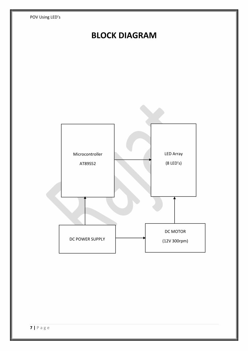
BLOCK DIAGRAM
Microcontroller
AT89S52
LED Array
(8 LED’s)
DC POWER SUPPLY
DC MOTOR
(12V 300rpm)
POV Using LED’s
8 | P a g e
Microcontroller: The AT89S52 is a low-power, high-performance CMOS 8-bit
microcontroller with 8K bytes of in-system programmable Flash memory. The
device is manufactured using Atmel’s high-density nonvolatile memory
technology and is compatible with the industry-standard 80C51 instruction set
and pin out. The on-chip Flash allows the program memory to be reprogrammed
in-system or by a conventional non-volatile memory programmer. By combining
a versatile 8-bit CPU with in-system programmable Flash on a monolithic chip,
the Atmel AT89S52 is a powerful microcontroller which provides a highly-flexible
and cost-effective solution to many embedded control applications. The
AT89S52 provides the following standard features: 8K bytes of Flash, 256 bytes
of RAM, 32 I/O lines, Watchdog timer, two data pointers, three 16-bit
timer/counters, a six-vector two-level interrupt architecture, a full duplex serial
port, on-chip oscillator, and clock circuitry. In addition, the AT89S52 is designed
with static logic for operation down to zero frequency and supports two
software selectable power saving modes. The Idle Mode stops the CPU while
allowing the RAM, timer/counters, serial port, and interrupt system to continue
functioning. The Power-down mode saves the RAM contents but freezes the
oscillator, disabling all other chip functions until the next interrupt or hardware
reset.

POV Using LED’s
9 | P a g e
LED ARRAY: LED array consists of 8 bright red LED’s is fixed in another side of
the arm of our project. These LEDs are connected with each of the port pin of
microcontroller, with a series current limiting resistor of 220 ohm. All the LED’s
are connected in active low logic i.e. common anode mode.
DC MOTOR: Repeated scanning of the display is must for continuous vision. This
task is achieved using circular rotation of the whole circuit assembly. So, we used
a DC motor as the prime mover. We are making use 12v 300RPM geared motor
with 6mm shaft.
DC POWER SUPPLY: For microcontroller, as well as the DC motor, a regulated
DC power supply is required. We have to provide +5V to the microcontroller,
while +12V to the motor. For 12v we are making use of an adaptor.
POV Using LED’s
10 | P a g e
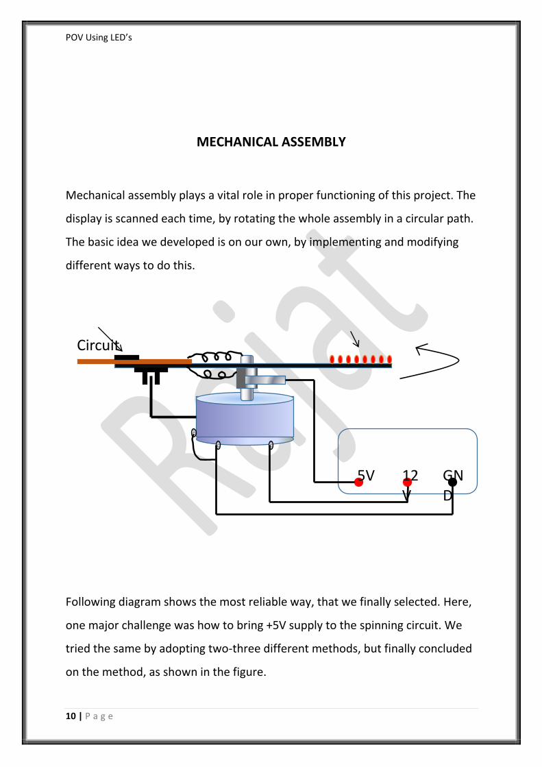
MECHANICAL ASSEMBLY
Mechanical assembly plays a vital role in proper functioning of this project. The
display is scanned each time, by rotating the whole assembly in a circular path.
The basic idea we developed is on our own, by implementing and modifying
different ways to do this.
Following diagram shows the most reliable way, that we finally selected. Here,
one major challenge was how to bring +5V supply to the spinning circuit. We
tried the same by adopting two-three different methods, but finally concluded
on the method, as shown in the figure.
Circuit
5V 12V
GND
POV Using LED’s
11 | P a g e
CIRCUITARY
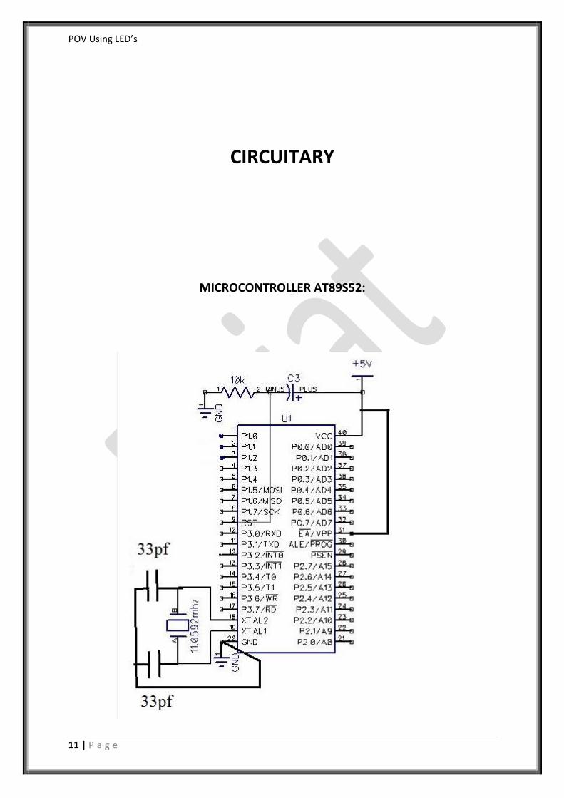
MICROCONTROLLER AT89S52:

POV Using LED’s
12 | P a g e
The basic circuit for the microcontroller is as shown in the above diagram.
It has a crystal of 11.0592 MHz which is connected between two 33pF
capacitors to generate clock frequency. Pin no 19 in input frequency and Pin no
18 is the output frequency. This crystal decides the operating frequency of the
microcontroller.
Since we are not making use any external program we are connecting the Pin
31, i.e. External Access pin to Vcc and make use of the code present in the
program memory of our microcontroller.
The important part of the microcontroller is the reset circuit. Reset is the active
High input. When RESET is set to high, 8051 goes back to the power on state.
The 8051 is reset by holding the RST high for at least two machine cycles and
returning it low.
There are two method of reset circuit:
1. Power on Reset
Initially charging of capacitor makes RST high.
When capacitor charges fully it blocks DC
2. Manual Reset: losing the switch momentarily will make RST high.
We make use of Power on reset in our Project.
POV Using LED’s
13 | P a g e
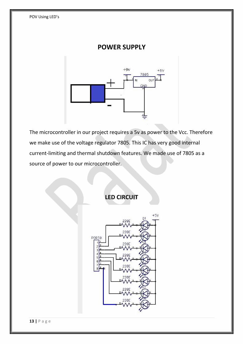
POWER SUPPLY
The microcontroller in our project requires a 5v as power to the Vcc. Therefore
we make use of the voltage regulator 7805. This IC has very good internal
current-limiting and thermal shutdown features. We made use of 7805 as a
source of power to our microcontroller.
LED CIRCUIT
POV Using LED’s
14 | P a g e
We are using LED’s in active low i.e. common anode mode. This mode will help
to make use of the sink current of the microcontroller without any driver
circuit to drive the LED’s. We have the current limiting resistors of 220 ohm
each connected to the 8 LED’s. These LED’s can be connected to any port of
the Microcontroller. We have made use of the PORT 1.
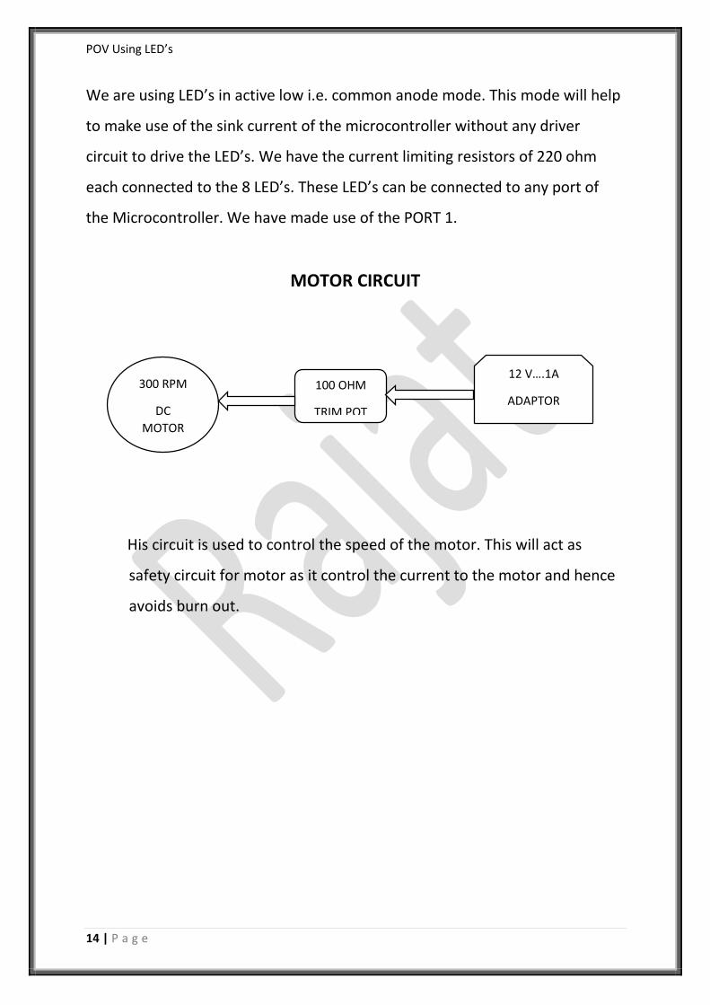
MOTOR CIRCUIT
His circuit is used to control the speed of the motor. This will act as
safety circuit for motor as it control the current to the motor and hence
avoids burn out.
300 RPM
DC
MOTOR
100 OHM
TRIM POT
12 V….1A
ADAPTOR
POV Using LED’s
15 | P a g e
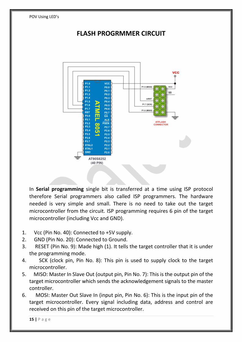
FLASH PROGRMMER CIRCUIT
In Serial programming single bit is transferred at a time using ISP protocol
therefore Serial programmers also called ISP programmers. The hardware
needed is very simple and small. There is no need to take out the target
microcontroller from the circuit. ISP programming requires 6 pin of the target
microcontroller (including Vcc and GND).
1. Vcc (Pin No. 40): Connected to +5V supply. 2. GND (Pin No. 20): Connected to Ground. 3. RESET (Pin No. 9): Made high (1). It tells the target controller that it is under
the programming mode. 4. SCK (clock pin, Pin No. 8): This pin is used to supply clock to the target
microcontroller. 5. MISO: Master In Slave Out (output pin, Pin No. 7): This is the output pin of the
target microcontroller which sends the acknowledgement signals to the master controller.
6. MOSI: Master Out Slave In (input pin, Pin No. 6): This is the input pin of the target microcontroller. Every signal including data, address and control are received on this pin of the target microcontroller.
POV Using LED’s
16 | P a g e
SOFTWARES USED
KEIL C51: The Keil C51 C Compiler for the 8051 microcontroller is the most popular 8051 C compiler in the world. It provides more features than any other 8051 C compiler available today. The C51 Compiler allows you to write 8051 microcontroller applications in C that, once compiled, have the efficiency and speed of assembly language. Language extensions in the C51 Compiler give you full access to all resources of the 8051.The C51 Compiler translates C source files into relocatable object modules which contain full symbolic information for debugging with the µVision Debugger or an in-circuit emulator. In addition to the object file, the compiler generates a listing file which may optionally include symbol table and cross reference information. We used the keil compiler to write the program code. The code is written in c language.
PROGSIP 1.72: This software is used to load flash into the microcontroller using
the 8051 programmer. This loads the hex file into the microcontroller and also has the feature to verify the loaded flash.
POV Using LED’s
17 | P a g e
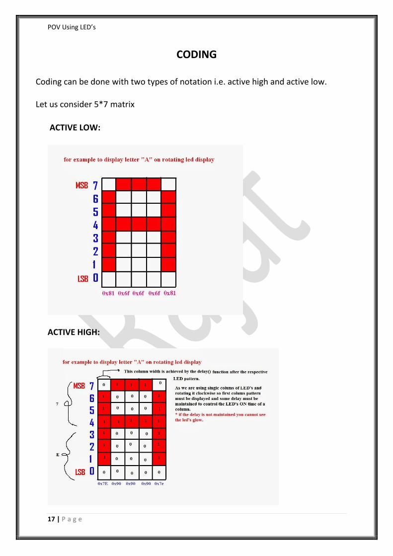
CODING
Coding can be done with two types of notation i.e. active high and active low. Let us consider 5*7 matrix
ACTIVE LOW:
ACTIVE HIGH:
POV Using LED’s
18 | P a g e
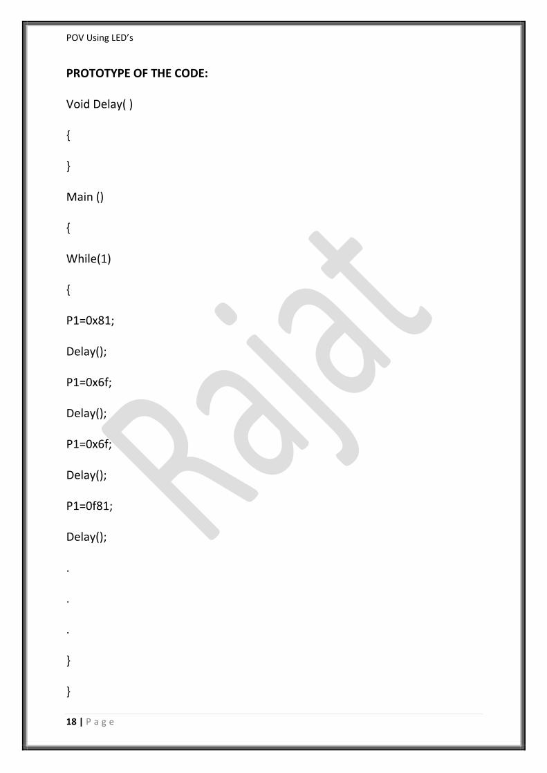
PROTOTYPE OF THE CODE:
Void Delay( )
{
}
Main ()
{
While(1)
{
P1=0x81;
Delay();
P1=0x6f;
Delay();
P1=0x6f;
Delay();
P1=0f81;
Delay();
.
.
.
}
}
POV Using LED’s
19 | P a g e
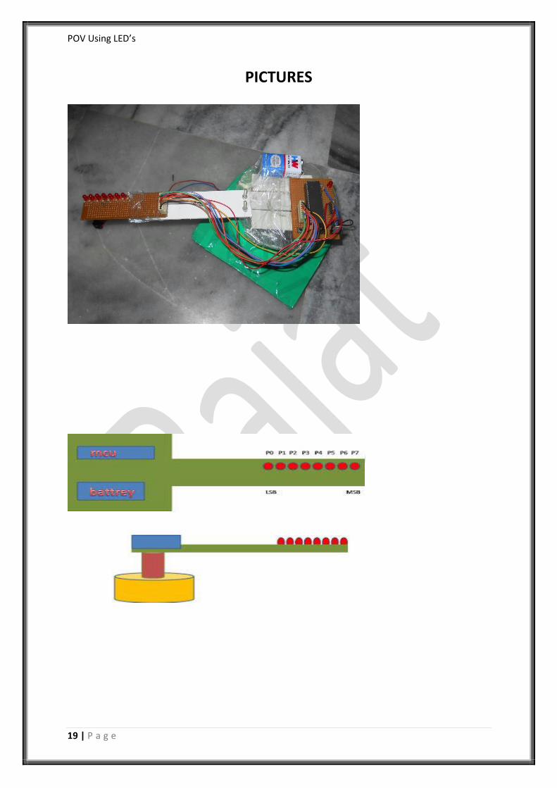
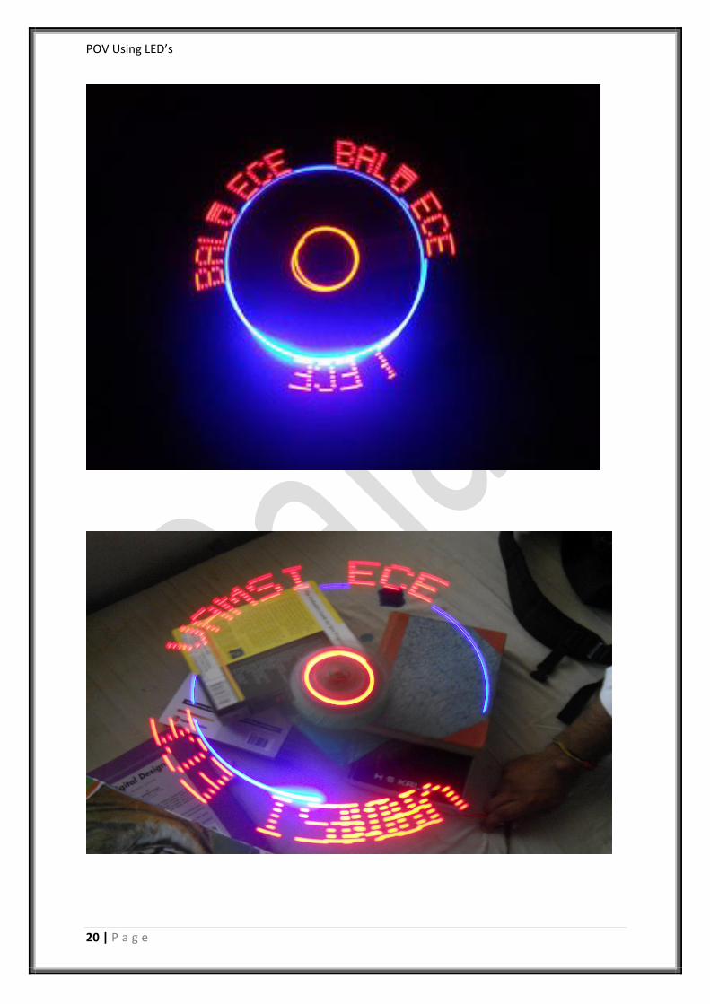
PICTURES
POV Using LED’s
20 | P a g e

POV Using LED’s
21 | P a g e
CONCLUSION
This is a cost effective solution for large public displays, information systems. It
can directly replace Railway station information displays, bus stands and many
more places.
Future improvements can involve the RGB colours of an image and display
image using this.
These systems are the latest and the most practical way creating semi-
transparent displays which can also be used to create three dimensional
effects by controlling the intensity of each display unit (LED).
This idea can be taken into the concept of 3D image.