Embed Size (px)
Citation preview
PERMIT-TO-INSTALL APPLICATION VOLUME I
For: AMERICAN MUNICIPAL POWER
GENERATING STATION
Submitted By: AMERICAN MUNICIPAL POWER-OHIO, INC.
May 2006
GT Environmental, Inc.
635 Park Meadow Road, Suite 112
Westerville, Ohio 43081 (614) 794-3570
PROJECT SUMMARY
For: AMERICAN MUNICIPAL POWER
GENERATING STATION
Submitted By: AMERICAN MUNICIPAL POWER-OHIO, INC.
May 2006
1 May 2006
SECTION 1 INTRODUCTION After a thorough and rigorous evaluation of various options to meet a significant portion of the electric power and energy needs of its municipal electric utility members, American Municipal Power-Ohio, Inc. (“AMP-Ohio”) determined the need to site, construct and operate new baseload power generation. As such, AMP-Ohio is proud to develop this flagship project, which will marry the reliability of pulverized coal technology with the best of the new generation of available and proven air pollution control technology. Specifically, AMP-Ohio proposes to construct and operate a new pulverized coal-fired power plant on a greenfield site in Meigs County, Ohio. To honor its municipal power function, AMP-Ohio has named the project the American Municipal Power Generating Station (“AMPGS”). The AMPGS will consist of two 480 MW-net electric generating units on a project footprint of approximately 1,000 acres. The power from AMPGS will be fully allocated to member participants, and AMPGS is not a merchant project. To the extent that some member participants determine to either not participate in the construction phase of the project or decrease their commitments, that capacity would first be offered to other participants and if not taken, the net capacity of the AMPGS will decrease accordingly. AMPGS will control emissions through the use of a comprehensive air pollution control system strategy. One of the critical steps in the development of AMPGS is obtaining an air permit to install (“PTI”) from Ohio EPA. As detailed in the attached materials, AMPGS will be a major stationary source, subject to the requirements of the Prevention of Significant Deterioration (“PSD”) program. Thus, attached is the AMPGS air PSD PTI permit application package, which consists of the following materials:
• PTI Application Forms Volume I • Emissions Calculations Volume I • BACT Analysis Volume II
• BAT Analysis Volume II
• Modeling - Class I Volume III
• Modeling - Class II Volume IV • Additional Impacts Analysis Volume IV
In addition to these required materials, AMP-Ohio has developed this project summary document to help Ohio EPA gain a better understanding of AMP-Ohio, the AMPGS project, the technology, fuel supply and control choices, and the regulatory standards AMPGS will meet.
2 May 2006
AMP-Ohio, its member participants and partner municipal power organizations look forward to working with Ohio EPA on this critical project. To that end, we encourage your agency to contact us with questions in an effort to maintain productive dialog throughout this process.
3 May 2006
SECTION 2 PROJECT PARTICIPANTS AMP-Ohio, formed in 1972 and headquartered in Columbus, is a nonprofit wholesale power supply and services provider owned by 114 member municipal electric systems in five states: Ohio, Pennsylvania, Virginia, West Virginia and Michigan. A 16-member board of trustees, representing member cities and villages, governs AMP-Ohio. AMP-Ohio’s core purpose is to provide cost-effective, reliable power supply to our member communities, through the strength of our commitment to public service. AMP-Ohio members currently receive power supply from a diversified resource portfolio that includes: wholesale power purchases, AMP-Ohio and member-owned coal, natural gas and diesel generation, hydroelectric resources, landfill gas and an innovative wind farm located near Bowling Green, Ohio. AMP-Ohio and its members have also supported fuel cell and solar facilities, as well as demand side programs that can reduce energy demand and consumption. As evidenced by this diverse power portfolio, AMP-Ohio and its members take their commitment to environmental stewardship seriously. In fact, AMP-Ohio has been the recipient of a number of awards recognizing its efforts for environmental stewardship and energy efficiency. Green Energy Ohio named the organization its Nonprofit of the Year for 2004; Ohio Municipal Electric Generation Agency Joint Venture 6, owned by 10 member communities and managed by AMP-Ohio, was the recipient of a 2005 Governor’s Award for Excellence in Energy Efficiency in Ohio (the second consecutive year the organization had been so recognized). In 1999, AMP-Ohio received the Energy Ally of the Year Award from U.S. EPA, and in 1998, AMP-Ohio received recognition from the U.S. Department of Energy, Energy Information Administration, for its commitment to environmental protection. The Ohio Department of Development, Office of Energy Efficiency, has commended AMP-Ohio, and Ohio Governor Bob Taft has recognized four AMP-Ohio member communities as Energy Smart Communities. To date, ninety-two (92) municipal communities in Ohio, Michigan, Pennsylvania, Virginia and West Virginia have joined together to participate in the AMPGS. Currently, seventy-five (75) of the participants are AMP-Ohio’s member communities in Ohio. In addition to individual public power communities, AMP-Ohio has partnered with municipal power organizations in Virginia and Michigan. Specifically, Blue Ridge Power Agency (“BRPA”), a Virginia-based nonprofit corporation established in 1988, will join AMP-Ohio’s member communities as a member of the AMPGS project. BRPA currently has 9 municipal members participating in the project. Likewise, Michigan South Central Power Agency (MSCPA) has joined the AMPGS project. MSCPA is a municipally-owned utility which serves five member communities.
4 May 2006
SECTION 3 TECHNOLOGY SUMMARY AMPGS will operate using two 480 MW-net pulverized-coal (“PC”) electric generation units. Prior to selecting PC technology, AMP-Ohio evaluated numerous other potential technologies for power generation, including: integrated gasification combined cycle (“IGCC”), circulating fluidized bed (“CFB”), wood-fired, natural gas combined cycle and waste fuel. As a critical step in this process, AMP-Ohio performed significant due diligence to ascertain the viability of each of the power options. This process included: significant research and evaluation of the technologies, discussions with manufacturers and vendors, site visits to existing and pilot project sites and engineering work to determine the scalability and reliability of each technology. This investigation process took multiple years and was performed to determine what type of technology AMP-Ohio should use for a self-build or power supply project. During this evaluation process, AMP-Ohio identified potential generation sites on which AMP-Ohio could build an electric generation station. To start, sites were identified and evaluated based on a variety of criteria, including: size, location, water access, raw material access and transmission access. After a list of viable sites was developed, AMP-Ohio began eliminating sites based on the criteria above, along with other intangible site factors. At the end of this process, AMP-Ohio identified final sites on which AMP-Ohio could develop a project. In addition to a potential self-build process, AMP-Ohio separately evaluated the possibility of entering into long-term power supply contracts with other suppliers or participating in generation projects under development by other entities. To kick off this process, AMP-Ohio invited companies to submit power supply proposals to AMP-Ohio. AMP-Ohio evaluated each of the responses to determine whether or not the proposal was viable, cost-effective and reliable. After significant review, AMP-Ohio narrowed the field of respondents and began a more detailed analysis of each of the projects. AMP-Ohio invested significant time and cost to evaluate each of the finalists and made visits to many of the project sites/proposed sites. At the conclusion of the process, AMP-Ohio evaluated the final self-build sites and the final third-party projects to determine which project best fit the long-term power supply needs of AMP-Ohio. After a significant evaluation of other power generation options, AMP-Ohio selected the AMPGS self-build PC project option. This selection was based on numerous criteria, including: need to control long-term power supply, size, cost, reliability, load-following ability, location to resources and environmental considerations. In this permit application, AMP-Ohio is not required to compare innovative power generation options with PC options as part of the BACT process. Specifically, on December 13, 2005, U.S. EPA determined that an applicant for a PSD permit does not need to consider, as part of the required BACT top-down analysis, any technology that redefines the basic design of the proposed source.1 Thus, these other technologies, including IGCC and CFB, have not been included in the attached BACT analysis. On April 11, 2006, the Secretary of Kentucky’s Environmental and Public Protection Cabinet issued a ruling, consistent with EPA’s 1 December 13, 2005 Letter from Stephen Page, Director, U.S. EPA Office of Air Quality, Planning and Standards to Paul Plath regarding “Best Available Control Technology Requirements for Proposed Coal-Fired Power Plant Projects.”
5 May 2006
determination, that IGCC does not have to be considered as part of the BACT process for a PC power plant because IGCC technology is not currently available.2 Even though no formal IGCC BACT analysis is required, AMP-Ohio did carefully evaluate the use of IGCC technology for the baseload project. However, there are several significant concerns with the IGCC technology as it exists today, including cost, operational flexibility and reliability. Ultimately, IGCC technology was eliminated from consideration. As stated above, AMPGS will be the flagship station for AMP-Ohio’s members. AMP-Ohio is not large enough, nor does it have the resources to own and operate a fleet of power generation to replace IGCC generating units in the event that IGCC does not operate as contemplated (i.e., low reliability) or does not operate at a reasonable, competitive cost to the municipal member participants. AMP-Ohio recognizes the future national need to develop innovative power generation technology and supports efforts to do so. As stated above, AMP-Ohio maintains a diverse power portfolio and continually looks for additional innovative projects. For instance, in 2005, American Electric Power (“AEP”) announced that it intended to site and build two IGCC plants. Shortly after the AEP announcement, AMP-Ohio formally asked AEP if AMP-Ohio could partner with AEP on the proposed Ohio IGGC project. AEP indicated that AMP-Ohio’s request was premature. AMP-Ohio continues to support the development of emerging power technologies, including IGCC and CFB. AMP-Ohio and its municipal partners will continue to pursue opportunities for involvement in projects utilizing emerging technology. In fact, a significant portion of the committed power capacity of the AMPGS is committed as replacement for the capacity currently provided to nearly 50 AMP-Ohio members from AMP-Ohio’s existing R.H. Gorsuch Generating Station (RHGS) near Marietta, Ohio. RHGS is a 1950’s vintage coal-fired, 194 MW net capacity power plant. AMP-Ohio is planning, in coordination with the in-service date of the AMPGS, to either: (i) repower RHGS with IGCC or an other emerging or innovative technology; or (ii) retire RHGS. Recently, AMP-Ohio issued a Solicitation of Interest to seek partners in the potential repowering process.
2 Decision of LuJuana Wilcher, Secretary of Kentucky’s Environmental and Public Protection Cabinet, April 11, 2006, www.eppc.ky.gov.
6 May 2006
SECTION 4 CONTROL EQUIPMENT SUMMARY As detailed in the attached application, AMPGS will employ a comprehensive air pollution control system to control air emissions. Specifically, AMPGS will limit the emission of Particulate Matter, PM10, PM2.5, SO2, NOx, CO, VOC, OC, HAPs, SO3, Hg, and other air contaminants through the use of the following methods:
• BACT emission limits (short-term and annual) • Fuel selection • Baghouse • FGD Scrubber* • Wet ESP • Best Combustion Practices/Boiler Control System • Boiler Design • Low NOx Burners • Overfire Air • SCR • Minimization of Heat Rate • Dust suppressants.
*Currently, no proven technology exists to control CO2 emissions; however, AMP-Ohio recognizes the need to continue to evaluate CO2 emerging technology. Therefore, AMP-Ohio has been and is currently evaluating CO2 control technology vendors. One vendor has performed initial laboratory testing for CO2 control and results are encouraging. While this demonstration was performed on a bench scale unit in a controlled environment (i.e., the technology is not commercially available), AMP-Ohio believes that the technology may be successfully scaled at some point in the future. As such, AMP-Ohio believes this technology is worth further investigation. If this technology becomes available and is selected, the FGD scrubber will use ammonia rather than limestone reagent in order to support the integration of the new technology. In addition, in anticipation of CO2 control, AMPGS will size the scrubber to accommodate future CO2 scrubbing.
7 May 2006
SECTION 5 FUEL FLEXIBILITY AMPGS will operate using coal as its fuel source. AMPGS will not have a specific coal supply and instead will rely on various coal blends to power AMPGS. AMPGS will likely purchase coal from a number of different suppliers with mines in Ohio, eastern states and/or western states. Since the cost of fuel is the greatest component of annual operating costs, AMPGS must have the maximum coal supply flexibility possible. Locking in a single coal supply or a coal from a single region of the country presents unacceptable financial and operating risks for AMP-Ohio and its members and is not necessary given the air pollution control systems AMPGS will employ. As commonly known, coals have differing constituents, depending on where the coal originates. There is no “best coal” from an emissions standpoint. For example, some coals may be higher in sulfur content, but lower in mercury content. In fact, coal from even the same region or same mine can vary in constituent content, depending on the seams mined at any given time. To be cost-effective and environmentally sound, AMPGS will manage air emissions by using coal-blends which include differing pollutant content coals. Coal blending will be considered “front-end” emissions management. As described in Section 4, AMPGS will also utilize a comprehensive air pollution control system to manage “back-end” emissions. Thus, AMPGS will be able to manage its financial and operating risks by utilizing numerous coal blends while contemporaneously meeting its regulatory obligations to control air emissions.
8 May 2006
SECTION 6 CLEAN AIR INTERSTATE RULE The Clean Air Interstate Rule (“CAIR”)3 regulates emissions from fossil-fuel fired boilers and turbines serving an electric generator with a nameplate capacity of greater than 25 MWe. Specifically, CAIR utilizes a cap-and-trade program approach to control the emissions of Nitrogen Oxide (“NOx”), Sulfur Dioxide (“SO2”) and Particulate Matter (“PM”). The CAIR program will begin in 2009 for NOx and 2010 for SO2. Currently, Ohio EPA has not promulgated its CAIR state program, but AMP-Ohio anticipates that Ohio’s CAIR program will be modeled in concert with the federal CAIR model rules. As detailed in the attached PSD PTI application, AMPGS will install equipment to significantly control the emissions of NOx, SO2 and PM. AMPGS acknowledges that it will be subject to the mandates of CAIR and Ohio’s CAIR rules upon start-up of the facility. CAIR will not require any specific emissions limits for NOx, SO2 or PM since it is a cap-and-trade program. However, AMPGS will be designed to control these pollutants to best available control technology standards.
3 The final CAIR rules revise 40 CFR Parts 51, 72, 73, 74, 77, 78 and 96 (70 FR 25162; May 12, 2005).
9 May 2006
SECTION 7 CLEAN AIR MERCURY RULE The Clean Air Mercury Rule (“CAMR”)4 regulates the emissions of mercury from electric generating units greater than 25 MWe through the use of a cap-and-trade program. Specifically, CAMR establishes two requirements that affected facilities must meet: (1) demonstrate compliance with an allowance-based cap-and-trade system; and (2) new units must maintain rolling 12-month average mercury emission rates consistent with the limitations in 40 CFR § 60.45a. The CAMR program begins in 2010. Ohio has not yet promulgated its state rule package to comply with the requirements of CAMR. U.S. EPA developed CAMR pursuant to Clean Air Act Section 111 (New Source Performance Standards) rather than Clean Air Act Section 112 (Maximum Achievable Control Technology). This statutory decision was based on U.S. EPA’s conclusion that power plant mercury emissions do not pose a hazard to public health that warrants regulation under Section 112. Specifically, U.S. EPA reasoned that mercury will be controlled appropriately by the air pollution controls installed to control NOx and SO2, so no independent Section 112 requirements for mercury were necessary. As detailed in the PSD permit application, AMPGS will control mercury emissions through the following control equipment: (1) baghouse and wet ESP to control the particulate forms of mercury; and (2) wet FGD and wet ESP to control the oxidized forms of mercury. Thus, as U.S. EPA intended, the NOx, SO2 and PM control equipment will also significantly reduce mercury emissions. AMPGS will be designed to meet and exceed the requirements of CAMR.
4 70 FR 28606 (May 18, 2005) Final CAMR rule with Revised NSPS for New and Existing Electric Utility Steam Generating Units.
10 May 2006
SECTION 8 MAXIMUM ACHIEVABLE CONTROL TECHNOLOGY (MACT) AMPGS is classified as an electric generation unit (i.e., its facility capacity is greater than 25 MWe), so the Industrial, Commercial and Institutional Boiler MACT, 40 CFR 63, Subpart DDDDD, does not apply. No site-specific MACT is necessary, pursuant to O.A.C. §3745-31-28, because electric utility steam generating units have been removed from the Clean Air Act Section 112(c) source category list.5 As noted in Section 7 of this project summary, AMPGS will comply with the Clean Air Mercury Rule.
5 70 FR 15994 (March 29, 2005). Final US EPA rule removing coal and oil-fired electric utility steam generating units from the CAA Section 112(c) list.
11 May 2006
SECTION 9 OTHER AIR POLLUTANTS OF CONCERN As noted in Section 8, AMPGS is not subject to any MACT standard since it is an electric generation unit. U.S. EPA has not identified any air toxics, other than mercury, that need to be regulated at electric generation units. However, Ohio has recognized the need to regulate emissions units that have the potential to emit more than 1 ton per year of any air toxic. Specifically, Ohio EPA maintains an Air Toxics Policy6 that regulates the emissions of air toxics from emissions units in Ohio. AMPGS has considered all air toxics emissions and will meet Ohio’s Air Toxics Policy requirements. See Volume IV of the AMPGS PSD application.
6 Ohio cites that its authority to regulate air toxics comes from its Best Available Technology regulations, O.A.C. §3745-31.
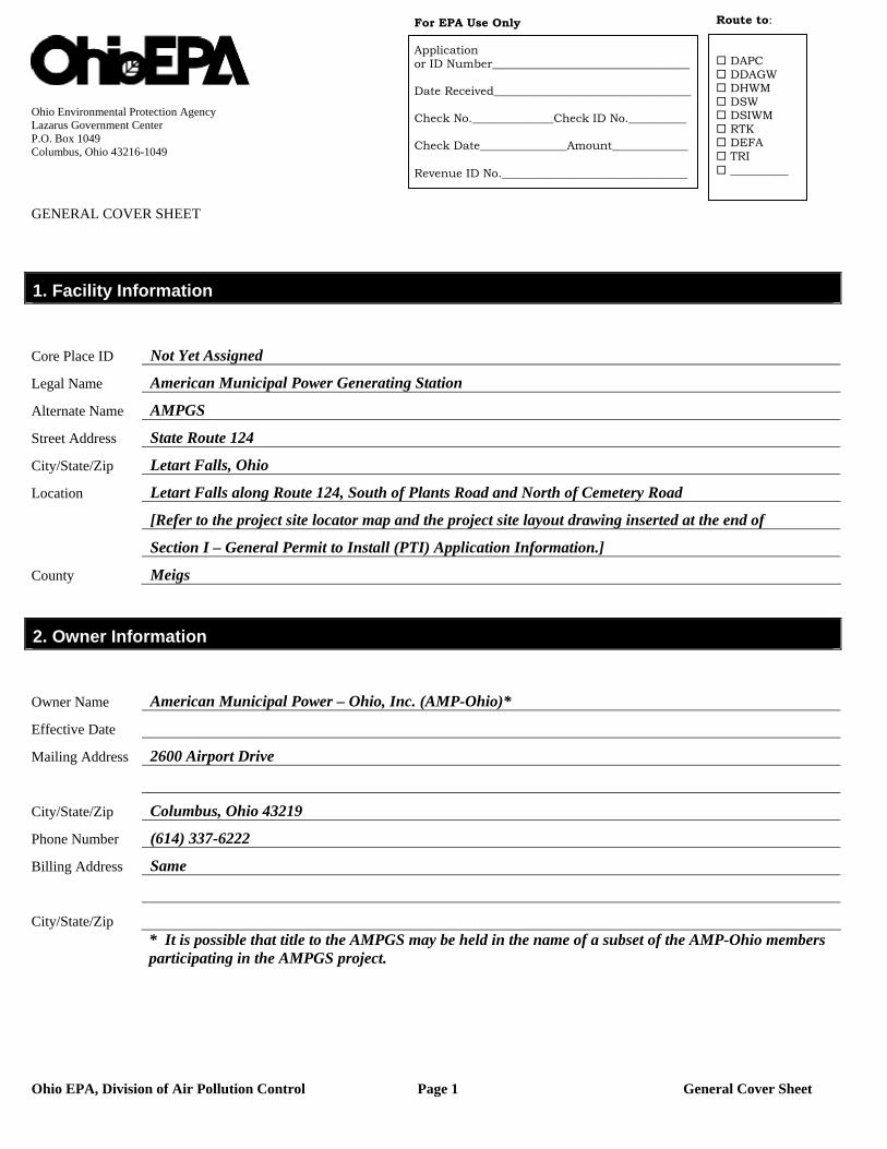
Ohio EPA, Division of Air Pollution Control Page 1 General Cover Sheet
Ohio Environmental Protection Agency Lazarus Government Center P.O. Box 1049 Columbus, Ohio 43216-1049 GENERAL COVER SHEET
1. Facility Information
Core Place ID Not Yet Assigned
Legal Name American Municipal Power Generating Station
Alternate Name AMPGS
Street Address State Route 124
City/State/Zip Letart Falls, Ohio
Location Letart Falls along Route 124, South of Plants Road and North of Cemetery Road
[Refer to the project site locator map and the project site layout drawing inserted at the end of
Section I – General Permit to Install (PTI) Application Information.]
County Meigs
2. Owner Information
Owner Name American Municipal Power – Ohio, Inc. (AMP-Ohio)*
Effective Date
Mailing Address 2600 Airport Drive
City/State/Zip Columbus, Ohio 43219
Phone Number (614) 337-6222
Billing Address Same
City/State/Zip * It is possible that title to the AMPGS may be held in the name of a subset of the AMP-Ohio members
participating in the AMPGS project.
Route to:
DAPC DDAGW DHWM DSW DSIWM RTK DEFA TRI __________
For EPA Use Only Application or ID Number__________________________________ Date Received__________________________________ Check No.______________Check ID No.__________ Check Date_______________Amount_____________ Revenue ID No.________________________________
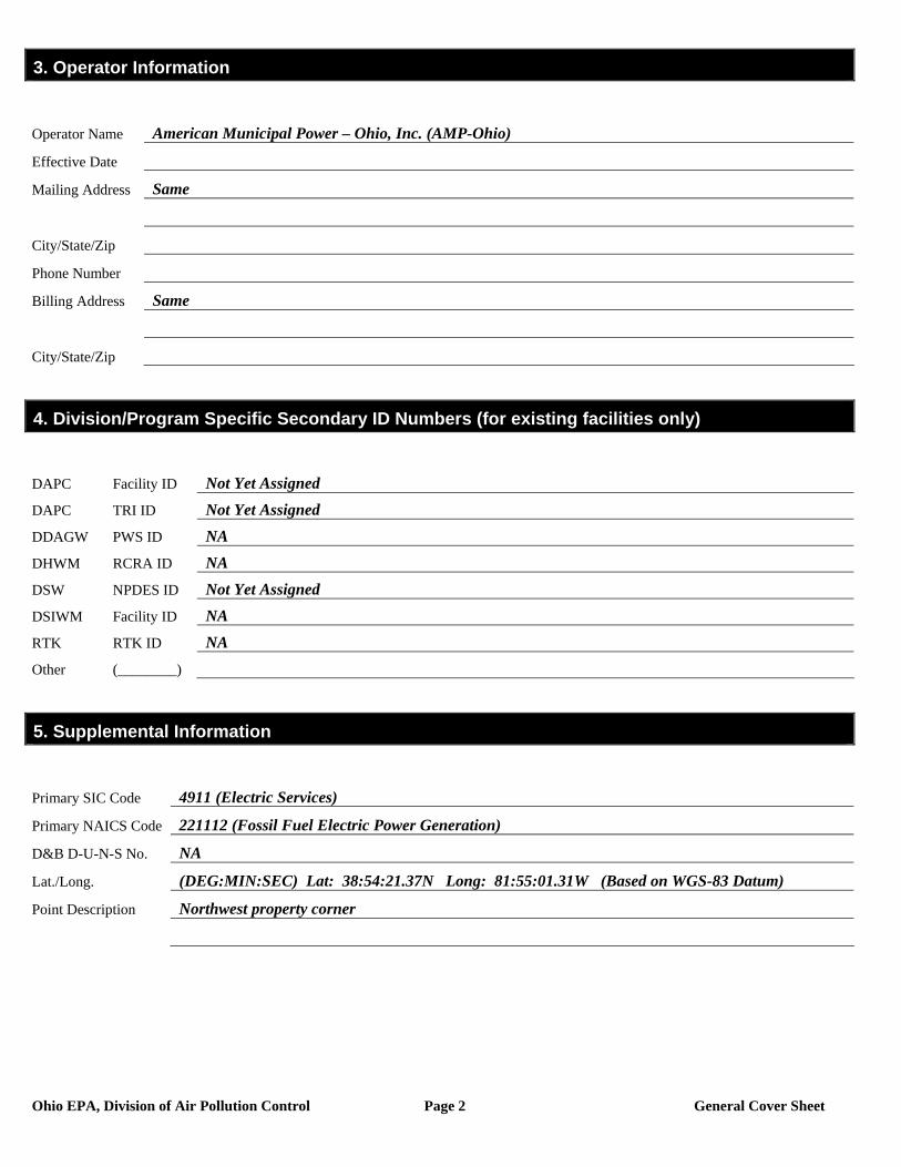
Ohio EPA, Division of Air Pollution Control Page 2 General Cover Sheet
3. Operator Information
Operator Name American Municipal Power – Ohio, Inc. (AMP-Ohio)
Effective Date
Mailing Address Same
City/State/Zip
Phone Number
Billing Address Same
City/State/Zip
4. Division/Program Specific Secondary ID Numbers (for existing facilities only)
DAPC Facility ID Not Yet Assigned
DAPC TRI ID Not Yet Assigned
DDAGW PWS ID NA
DHWM RCRA ID NA
DSW NPDES ID Not Yet Assigned
DSIWM Facility ID NA
RTK RTK ID NA
Other (________)
5. Supplemental Information
Primary SIC Code 4911 (Electric Services)
Primary NAICS Code 221112 (Fossil Fuel Electric Power Generation)
D&B D-U-N-S No. NA
Lat./Long. (DEG:MIN:SEC) Lat: 38:54:21.37N Long: 81:55:01.31W (Based on WGS-83 Datum)
Point Description Northwest property corner
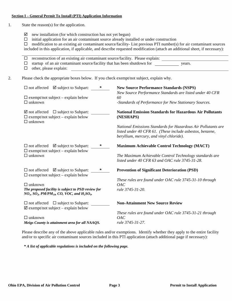
Section I – General Permit To Install (PTI) Application Information
Ohio EPA, Division of Air Pollution Control Page 3 Permit to Install Application
1. State the reason(s) for the application.
new installation (for which construction has not yet begun) initial application for an air contaminant source already installed or under construction modification to an existing air contaminant source/facility- List previous PTI number(s) for air contaminant sources
included in this application, if applicable, and describe requested modification (attach an additional sheet, if necessary):
reconstruction of an existing air contaminant source/facility. Please explain: startup of an air contaminant source/facility that has been shutdown for years. other, please explain:
2. Please check the appropriate boxes below. If you check exempt/not subject, explain why.
not affected subject to Subpart: * New Source Performance Standards (NSPS)
exempt/not subject – explain below New Source Performance Standards are listed under 40 CFR 60
unknown -Standards of Performance for New Stationary Sources.
not affected subject to Subpart: National Emission Standards for Hazardous Air Pollutants exempt/not subject – explain below (NESHAPS) unknown
National Emissions Standards for Hazardous Air Pollutants are listed under 40 CFR 61. (These include asbestos, benzene, beryllium, mercury, and vinyl chloride).
not affected subject to Subpart: * Maximum Achievable Control Technology (MACT) exempt/not subject – explain below unknown The Maximum Achievable Control Technology standards are
listed under 40 CFR 63 and OAC rule 3745-31-28.
not affected subject to Subpart: * Prevention of Significant Deterioration (PSD) exempt/not subject – explain below
unknown These rules are found under OAC rule 3745-31-10 through OAC
The proposed facility is subject to PSD review for NOx, SO2, PM/PM10, CO, VOC, and H2SO4.
rule 3745-31-20.
not affected subject to Subpart: Non-Attainment New Source Review exempt/not subject – explain below
unknown These rules are found under OAC rule 3745-31-21 through OAC
Meigs County is attainment area for all NAAQS. rule 3745-31-27.
Please describe any of the above applicable rules and/or exemptions. Identify whether they apply to the entire facility and/or to specific air contaminant sources included in this PTI application (attach additional page if necessary):
* A list of applicable regulations is included on the following page.
Section I – General Permit To Install (PTI) Application Information
Ohio EPA, Division of Air Pollution Control Page 4 Permit to Install Application Revised May 9, 2007
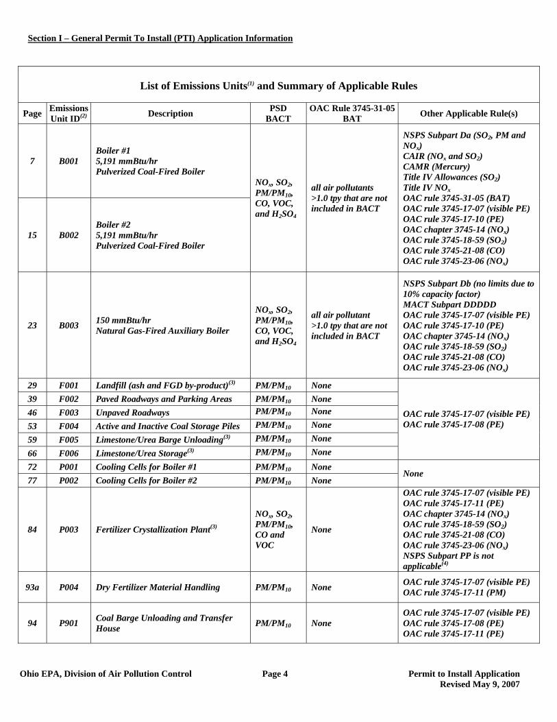
List of Emissions Units(1) and Summary of Applicable Rules
Page Emissions Unit ID(2) Description PSD
BACT OAC Rule 3745-31-05
BAT Other Applicable Rule(s)
7 B001 Boiler #1 5,191 mmBtu/hr Pulverized Coal-Fired Boiler
15 B002 Boiler #2 5,191 mmBtu/hr Pulverized Coal-Fired Boiler
NOx, SO2, PM/PM10, CO, VOC, and H2SO4
all air pollutants >1.0 tpy that are not included in BACT
NSPS Subpart Da (SO2, PM and NOx) CAIR (NOx and SO2) CAMR (Mercury) Title IV Allowances (SO2) Title IV NOx OAC rule 3745-31-05 (BAT) OAC rule 3745-17-07 (visible PE) OAC rule 3745-17-10 (PE) OAC chapter 3745-14 (NOx) OAC rule 3745-18-59 (SO2) OAC rule 3745-21-08 (CO) OAC rule 3745-23-06 (NOx)
23 B003 150 mmBtu/hr Natural Gas-Fired Auxiliary Boiler
NOx, SO2, PM/PM10, CO, VOC, and H2SO4
all air pollutant >1.0 tpy that are not included in BACT
NSPS Subpart Db (no limits due to 10% capacity factor) MACT Subpart DDDDD OAC rule 3745-17-07 (visible PE) OAC rule 3745-17-10 (PE) OAC chapter 3745-14 (NOx) OAC rule 3745-18-59 (SO2) OAC rule 3745-21-08 (CO) OAC rule 3745-23-06 (NOx)
29 F001 Landfill (ash and FGD by-product)(3) PM/PM10 None 39 F002 Paved Roadways and Parking Areas PM/PM10 None 46 F003 Unpaved Roadways PM/PM10 None 53 F004 Active and Inactive Coal Storage Piles PM/PM10 None 59 F005 Limestone/Urea Barge Unloading(3) PM/PM10 None 66 F006 Limestone/Urea Storage(3) PM/PM10 None
OAC rule 3745-17-07 (visible PE) OAC rule 3745-17-08 (PE)
72 P001 Cooling Cells for Boiler #1 PM/PM10 None 77 P002 Cooling Cells for Boiler #2 PM/PM10 None
None
84 P003 Fertilizer Crystallization Plant(3)
NOx, SO2, PM/PM10, CO and VOC
None
OAC rule 3745-17-07 (visible PE) OAC rule 3745-17-11 (PE) OAC chapter 3745-14 (NOx) OAC rule 3745-18-59 (SO2) OAC rule 3745-21-08 (CO) OAC rule 3745-23-06 (NOx) NSPS Subpart PP is not applicable(4)
93a P004 Dry Fertilizer Material Handling PM/PM10 None OAC rule 3745-17-07 (visible PE) OAC rule 3745-17-11 (PM)
94 P901 Coal Barge Unloading and Transfer House PM/PM10 None
OAC rule 3745-17-07 (visible PE) OAC rule 3745-17-08 (PE) OAC rule 3745-17-11 (PE)
Section I – General Permit To Install (PTI) Application Information
Ohio EPA, Division of Air Pollution Control Page 5 Permit to Install Application Revised May 9, 2007
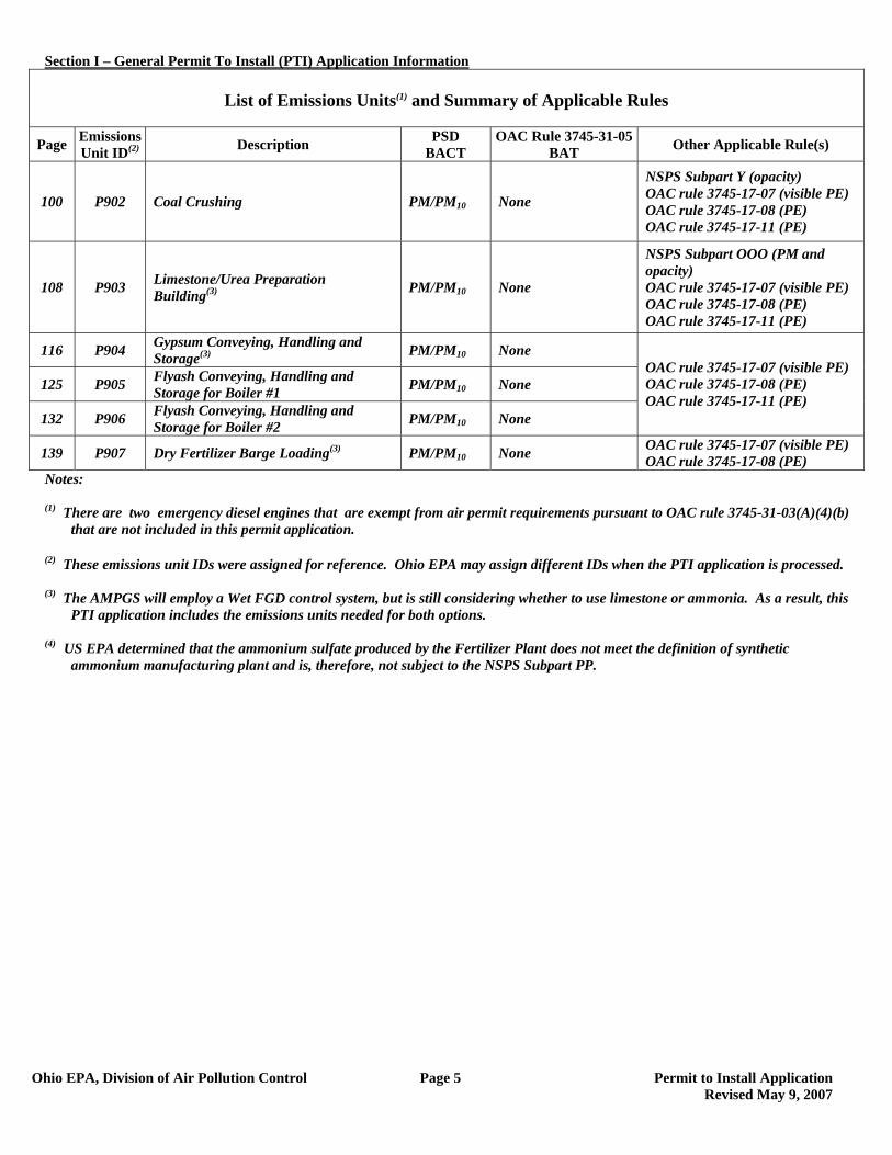
List of Emissions Units(1) and Summary of Applicable Rules
Page Emissions Unit ID(2) Description PSD
BACT OAC Rule 3745-31-05
BAT Other Applicable Rule(s)
100 P902 Coal Crushing PM/PM10 None
NSPS Subpart Y (opacity) OAC rule 3745-17-07 (visible PE) OAC rule 3745-17-08 (PE) OAC rule 3745-17-11 (PE)
108 P903 Limestone/Urea Preparation Building(3) PM/PM10 None
NSPS Subpart OOO (PM and opacity) OAC rule 3745-17-07 (visible PE) OAC rule 3745-17-08 (PE) OAC rule 3745-17-11 (PE)
116 P904 Gypsum Conveying, Handling and Storage(3) PM/PM10 None
125 P905 Flyash Conveying, Handling and Storage for Boiler #1 PM/PM10 None
132 P906 Flyash Conveying, Handling and Storage for Boiler #2 PM/PM10 None
OAC rule 3745-17-07 (visible PE) OAC rule 3745-17-08 (PE) OAC rule 3745-17-11 (PE)
139 P907 Dry Fertilizer Barge Loading(3) PM/PM10 None OAC rule 3745-17-07 (visible PE) OAC rule 3745-17-08 (PE)
Notes:
(1) There are two emergency diesel engines that are exempt from air permit requirements pursuant to OAC rule 3745-31-03(A)(4)(b) that are not included in this permit application.
(2) These emissions unit IDs were assigned for reference. Ohio EPA may assign different IDs when the PTI application is processed.
(3) The AMPGS will employ a Wet FGD control system, but is still considering whether to use limestone or ammonia. As a result, this
PTI application includes the emissions units needed for both options.
(4) US EPA determined that the ammonium sulfate produced by the Fertilizer Plant does not meet the definition of synthetic ammonium manufacturing plant and is, therefore, not subject to the NSPS Subpart PP.
Section I – General Permit To Install (PTI) Application Information
Ohio EPA, Division of Air Pollution Control Page 7 Permit to Install Application
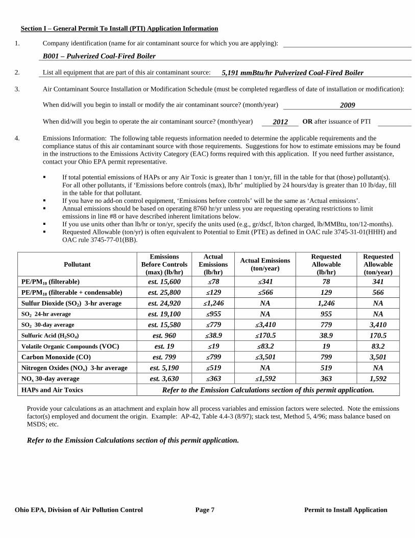
1. Company identification (name for air contaminant source for which you are applying):
B001 – Pulverized Coal-Fired Boiler 2. List all equipment that are part of this air contaminant source: 5,191 mmBtu/hr Pulverized Coal-Fired Boiler 3. Air Contaminant Source Installation or Modification Schedule (must be completed regardless of date of installation or modification): When did/will you begin to install or modify the air contaminant source? (month/year) 2009 When did/will you begin to operate the air contaminant source? (month/year) 2012 OR after issuance of PTI 4. Emissions Information: The following table requests information needed to determine the applicable requirements and the compliance status of this air contaminant source with those requirements. Suggestions for how to estimate emissions may be found in the instructions to the Emissions Activity Category (EAC) forms required with this application. If you need further assistance, contact your Ohio EPA permit representative.
If total potential emissions of HAPs or any Air Toxic is greater than 1 ton/yr, fill in the table for that (those) pollutant(s).
For all other pollutants, if ‘Emissions before controls (max), lb/hr’ multiplied by 24 hours/day is greater than 10 lb/day, fill in the table for that pollutant.
If you have no add-on control equipment, ‘Emissions before controls’ will be the same as ‘Actual emissions’. Annual emissions should be based on operating 8760 hr/yr unless you are requesting operating restrictions to limit
emissions in line #8 or have described inherent limitations below. If you use units other than lb/hr or ton/yr, specify the units used (e.g., gr/dscf, lb/ton charged, lb/MMBtu, ton/12-months). Requested Allowable (ton/yr) is often equivalent to Potential to Emit (PTE) as defined in OAC rule 3745-31-01(HHH) and
OAC rule 3745-77-01(BB).
Pollutant Emissions
Before Controls (max) (lb/hr)
Actual Emissions
(lb/hr)
Actual Emissions (ton/year)
Requested Allowable
(lb/hr)
Requested Allowable (ton/year)
PE/PM10 (filterable) est. 15,600 #78 #341 78 341 PE/PM10 (filterable + condensable) est. 25,800 #129 #566 129 566 Sulfur Dioxide (SO2) 3-hr average est. 24,920 #1,246 NA 1,246 NA SO2 24-hr average est. 19,100 #955 NA 955 NA SO2 30-day average est. 15,580 #779 #3,410 779 3,410 Sulfuric Acid (H2SO4) est. 960 #38.9 #170.5 38.9 170.5 Volatile Organic Compounds (VOC) est. 19 #19 #83.2 19 83.2 Carbon Monoxide (CO) est. 799 #799 #3,501 799 3,501 Nitrogen Oxides (NOx) 3-hr average est. 5,190 #519 NA 519 NA NOx 30-day average est. 3,630 #363 #1,592 363 1,592 HAPs and Air Toxics Refer to the Emission Calculations section of this permit application.
Provide your calculations as an attachment and explain how all process variables and emission factors were selected. Note the emissions factor(s) employed and document the origin. Example: AP-42, Table 4.4-3 (8/97); stack test, Method 5, 4/96; mass balance based on MSDS; etc.
Refer to the Emission Calculations section of this permit application.
Section I – General Permit To Install (PTI) Application Information
Ohio EPA, Division of Air Pollution Control Page 8 Permit to Install Application
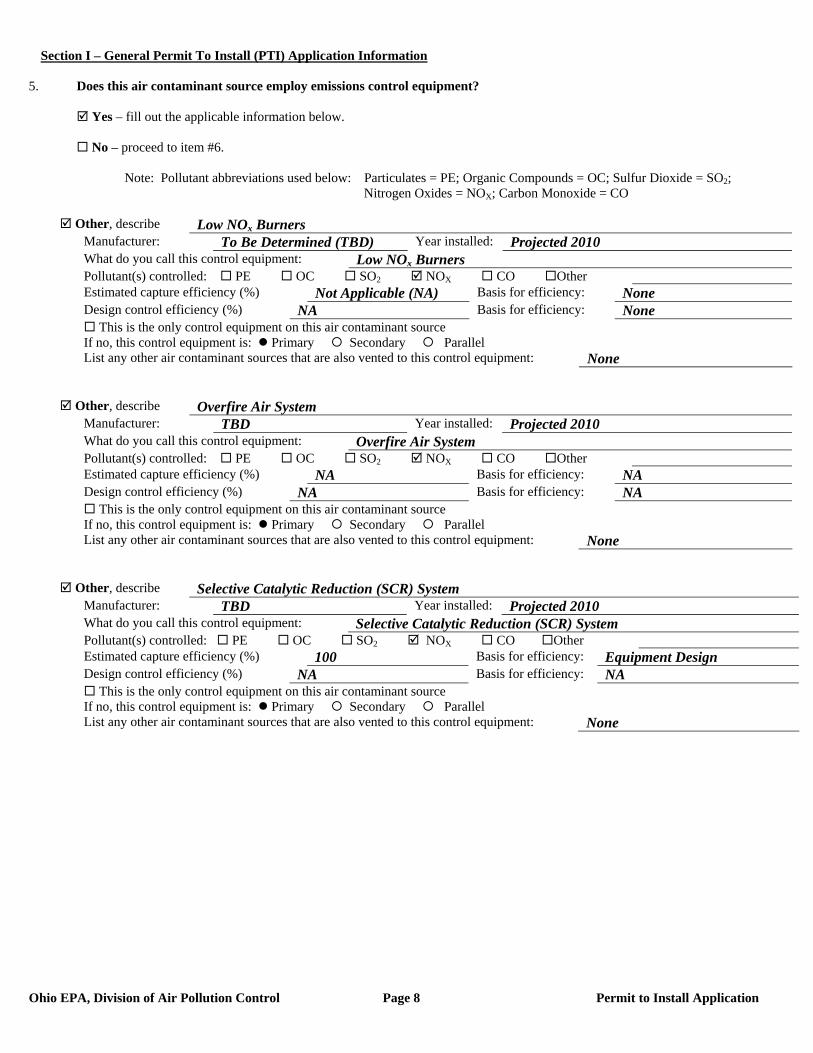
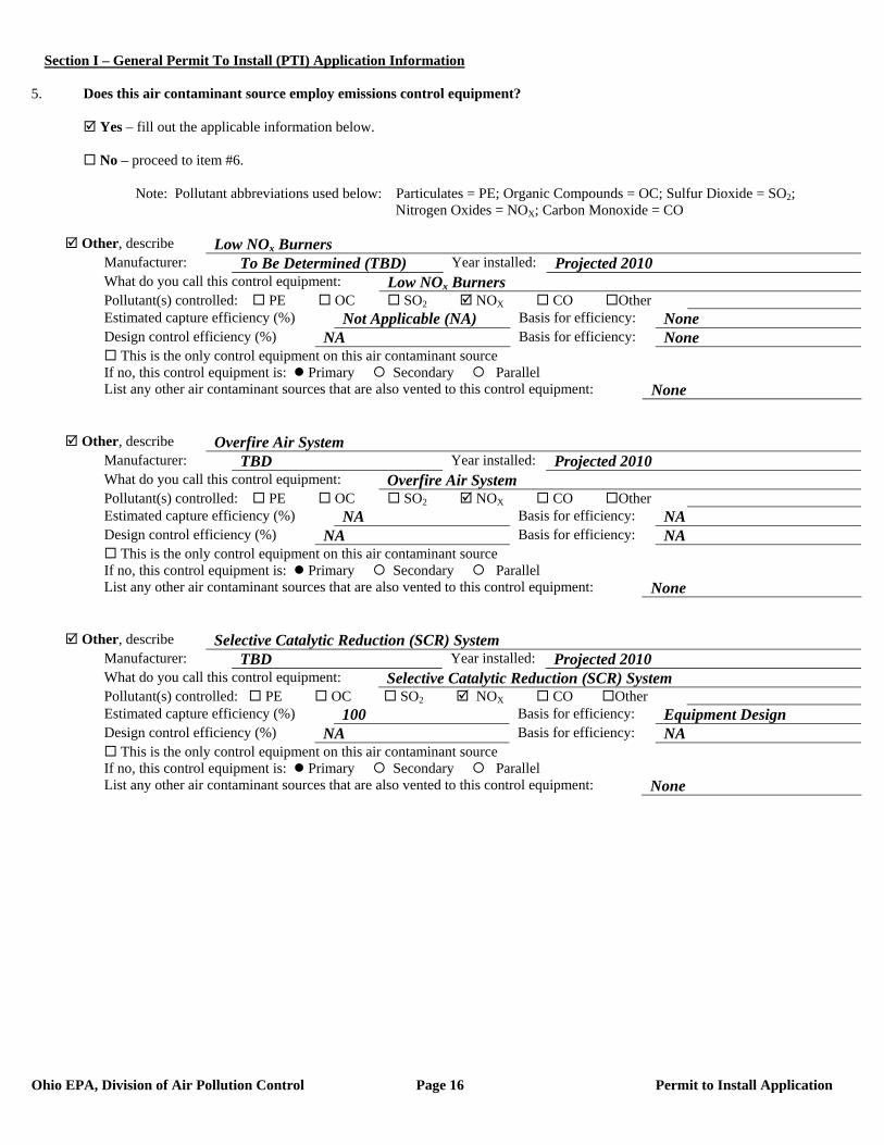
5. Does this air contaminant source employ emissions control equipment? Yes – fill out the applicable information below. No – proceed to item #6. Note: Pollutant abbreviations used below: Particulates = PE; Organic Compounds = OC; Sulfur Dioxide = SO2; Nitrogen Oxides = NOX; Carbon Monoxide = CO
Other, describe Low NOx Burners Manufacturer: To Be Determined (TBD) Year installed: Projected 2010 What do you call this control equipment: Low NOx Burners Pollutant(s) controlled: PE OC SO2 NOX CO Other Estimated capture efficiency (%) Not Applicable (NA) Basis for efficiency: None Design control efficiency (%) NA Basis for efficiency: None This is the only control equipment on this air contaminant source If no, this control equipment is: Primary Secondary Parallel List any other air contaminant sources that are also vented to this control equipment: None
Other, describe Overfire Air System Manufacturer: TBD Year installed: Projected 2010 What do you call this control equipment: Overfire Air System Pollutant(s) controlled: PE OC SO2 NOX CO Other Estimated capture efficiency (%) NA Basis for efficiency: NA Design control efficiency (%) NA Basis for efficiency: NA This is the only control equipment on this air contaminant source If no, this control equipment is: Primary Secondary Parallel List any other air contaminant sources that are also vented to this control equipment: None
Other, describe Selective Catalytic Reduction (SCR) System Manufacturer: TBD Year installed: Projected 2010 What do you call this control equipment: Selective Catalytic Reduction (SCR) System Pollutant(s) controlled: PE OC SO2 NOX CO Other Estimated capture efficiency (%) 100 Basis for efficiency: Equipment Design Design control efficiency (%) NA Basis for efficiency: NA This is the only control equipment on this air contaminant source If no, this control equipment is: Primary Secondary Parallel List any other air contaminant sources that are also vented to this control equipment: None
Section I – General Permit To Install (PTI) Application Information
Ohio EPA, Division of Air Pollution Control Page 9 Permit to Install Application
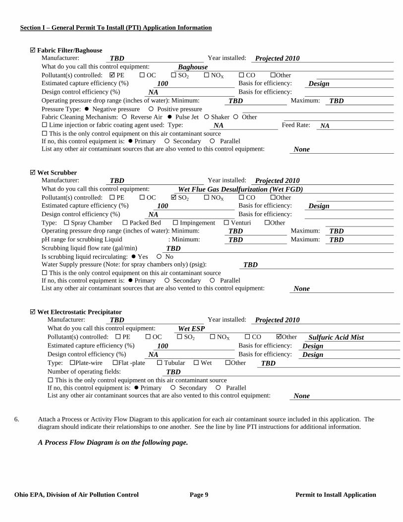
Fabric Filter/Baghouse Manufacturer: TBD Year installed: Projected 2010 What do you call this control equipment: Baghouse Pollutant(s) controlled: PE OC SO2 NOX CO Other Estimated capture efficiency (%) 100 Basis for efficiency: Design Design control efficiency (%) NA Basis for efficiency: Operating pressure drop range (inches of water): Minimum: TBD Maximum: TBD Pressure Type: Negative pressure Positive pressure Fabric Cleaning Mechanism: Reverse Air Pulse Jet Shaker Other Lime injection or fabric coating agent used: Type: NA Feed Rate: NA This is the only control equipment on this air contaminant source If no, this control equipment is: Primary Secondary Parallel List any other air contaminant sources that are also vented to this control equipment: None
Wet Scrubber Manufacturer: TBD Year installed: Projected 2010 What do you call this control equipment: Wet Flue Gas Desulfurization (Wet FGD) Pollutant(s) controlled: PE OC SO2 NOX CO Other Estimated capture efficiency (%) 100 Basis for efficiency: Design Design control efficiency (%) NA Basis for efficiency: Type: Spray Chamber Packed Bed Impingement Venturi Other Operating pressure drop range (inches of water): Minimum: TBD Maximum: TBD pH range for scrubbing Liquid : Minimum: TBD Maximum: TBD Scrubbing liquid flow rate (gal/min) TBD Is scrubbing liquid recirculating: Yes No Water Supply pressure (Note: for spray chambers only) (psig): TBD This is the only control equipment on this air contaminant source If no, this control equipment is: Primary Secondary Parallel List any other air contaminant sources that are also vented to this control equipment: None
Wet Electrostatic Precipitator Manufacturer: TBD Year installed: Projected 2010 What do you call this control equipment: Wet ESP Pollutant(s) controlled: PE OC SO2 NOX CO Other Sulfuric Acid Mist Estimated capture efficiency (%) 100 Basis for efficiency: Design Design control efficiency (%) NA Basis for efficiency: Design Type: Plate-wire Flat -plate Tubular Wet Other TBD Number of operating fields: TBD This is the only control equipment on this air contaminant source If no, this control equipment is: Primary Secondary Parallel List any other air contaminant sources that are also vented to this control equipment: None
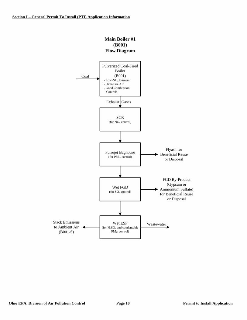
6. Attach a Process or Activity Flow Diagram to this application for each air contaminant source included in this application. The
diagram should indicate their relationships to one another. See the line by line PTI instructions for additional information. A Process Flow Diagram is on the following page.
Section I – General Permit To Install (PTI) Application Information
Ohio EPA, Division of Air Pollution Control Page 10 Permit to Install Application
Wet ESP(for H2SO4 and condensable
PM10 control)
Pulverized Coal-Fired Boiler(B001)
- Low-NOx Burners- Over-Fire Air- Good Combustion
Controls
SCR (for NOx control)
Pulsejet Baghouse(for PM10 control)
Wet FGD(for SO2 control)
Coal
Exhaust Gases
Stack Emissions to Ambient Air
(B001-S)
Main Boiler #1(B001)
Flow Diagram
Flyash for Beneficial Reuse
or Disposal
FGD By-Product (Gypsum or
Ammonium Sulfate) for Beneficial Reuse
or Disposal
Wastewater
Section I – General Permit To Install (PTI) Application Information
Ohio EPA, Division of Air Pollution Control Page 11 Permit to Install Application
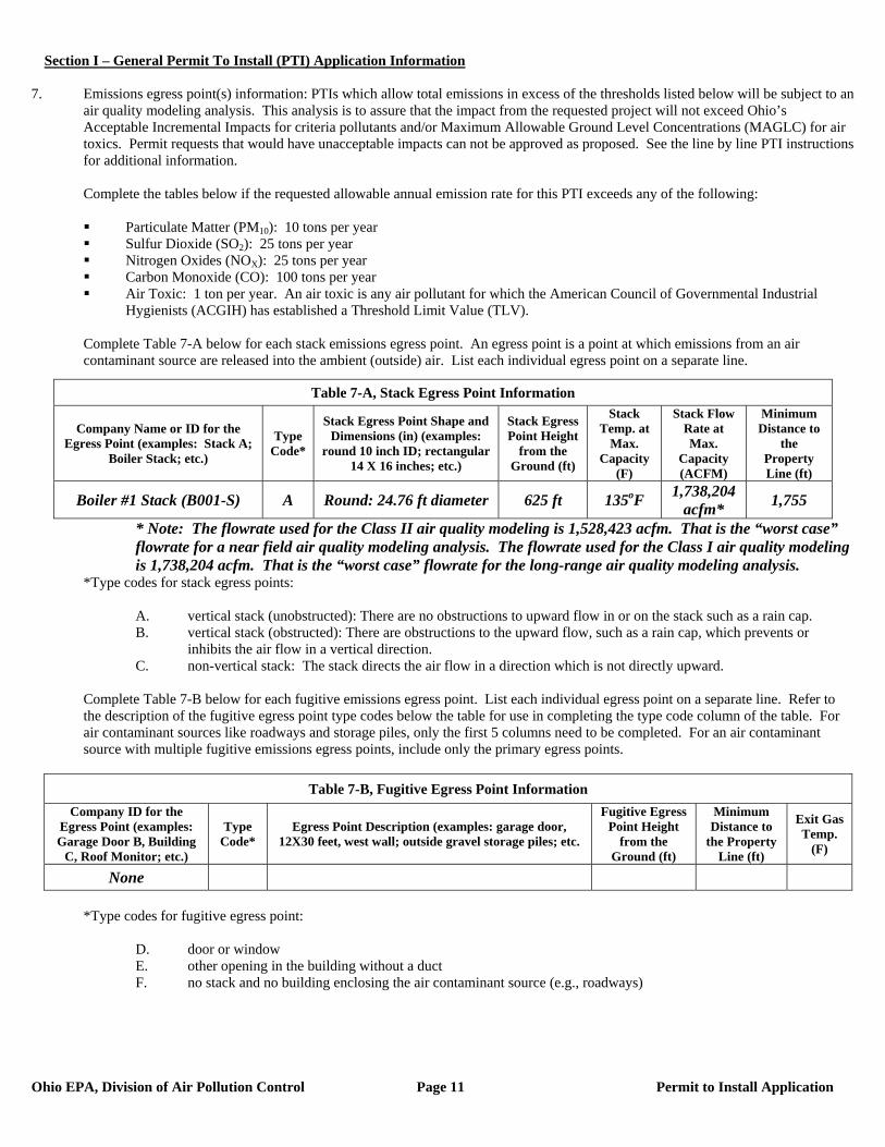
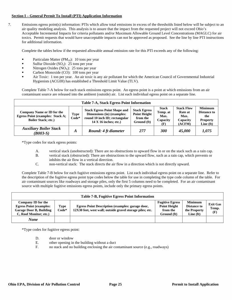
7. Emissions egress point(s) information: PTIs which allow total emissions in excess of the thresholds listed below will be subject to an
air quality modeling analysis. This analysis is to assure that the impact from the requested project will not exceed Ohio’s Acceptable Incremental Impacts for criteria pollutants and/or Maximum Allowable Ground Level Concentrations (MAGLC) for air toxics. Permit requests that would have unacceptable impacts can not be approved as proposed. See the line by line PTI instructions for additional information.
Complete the tables below if the requested allowable annual emission rate for this PTI exceeds any of the following:
Particulate Matter (PM10): 10 tons per year Sulfur Dioxide (SO2): 25 tons per year Nitrogen Oxides (NOX): 25 tons per year Carbon Monoxide (CO): 100 tons per year Air Toxic: 1 ton per year. An air toxic is any air pollutant for which the American Council of Governmental Industrial
Hygienists (ACGIH) has established a Threshold Limit Value (TLV).
Complete Table 7-A below for each stack emissions egress point. An egress point is a point at which emissions from an air contaminant source are released into the ambient (outside) air. List each individual egress point on a separate line.
* Note: The flowrate used for the Class II air quality modeling is 1,528,423 acfm. That is the “worst case” flowrate for a near field air quality modeling analysis. The flowrate used for the Class I air quality modeling is 1,738,204 acfm. That is the “worst case” flowrate for the long-range air quality modeling analysis.
*Type codes for stack egress points:
A. vertical stack (unobstructed): There are no obstructions to upward flow in or on the stack such as a rain cap. B. vertical stack (obstructed): There are obstructions to the upward flow, such as a rain cap, which prevents or
inhibits the air flow in a vertical direction. C. non-vertical stack: The stack directs the air flow in a direction which is not directly upward.
Complete Table 7-B below for each fugitive emissions egress point. List each individual egress point on a separate line. Refer to the description of the fugitive egress point type codes below the table for use in completing the type code column of the table. For air contaminant sources like roadways and storage piles, only the first 5 columns need to be completed. For an air contaminant source with multiple fugitive emissions egress points, include only the primary egress points.
Table 7-B, Fugitive Egress Point Information
Company ID for the Egress Point (examples: Garage Door B, Building
C, Roof Monitor; etc.)
Type Code*
Egress Point Description (examples: garage door, 12X30 feet, west wall; outside gravel storage piles; etc.
Fugitive Egress Point Height
from the Ground (ft)
Minimum Distance to
the Property Line (ft)
Exit Gas Temp.
(F)
None
*Type codes for fugitive egress point:
D. door or window E. other opening in the building without a duct F. no stack and no building enclosing the air contaminant source (e.g., roadways)
Table 7-A, Stack Egress Point Information
Company Name or ID for the Egress Point (examples: Stack A;
Boiler Stack; etc.)
Type Code*
Stack Egress Point Shape and Dimensions (in) (examples:
round 10 inch ID; rectangular 14 X 16 inches; etc.)
Stack Egress Point Height
from the Ground (ft)
Stack Temp. at
Max. Capacity
(F)
Stack Flow Rate at Max.
Capacity (ACFM)
Minimum Distance to
the Property Line (ft)
Boiler #1 Stack (B001-S) A Round: 24.76 ft diameter 625 ft 135oF 1,738,204 acfm* 1,755
Section I – General Permit To Install (PTI) Application Information
Ohio EPA, Division of Air Pollution Control Page 12 Permit to Install Application
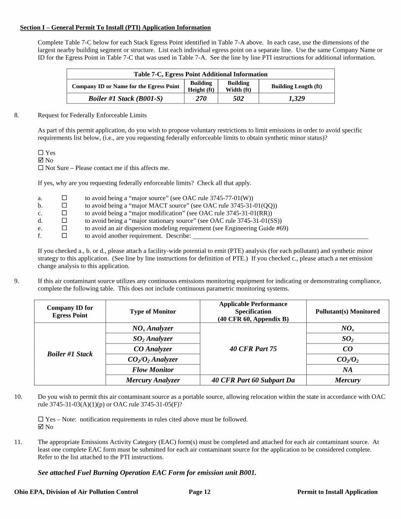
Complete Table 7-C below for each Stack Egress Point identified in Table 7-A above. In each case, use the dimensions of the largest nearby building segment or structure. List each individual egress point on a separate line. Use the same Company Name or ID for the Egress Point in Table 7-C that was used in Table 7-A. See the line by line PTI instructions for additional information.
Table 7-C, Egress Point Additional Information
Company ID or Name for the Egress Point Building Height (ft)
Building Width (ft) Building Length (ft)
Boiler #1 Stack (B001-S) 270 502 1,329 8. Request for Federally Enforceable Limits
As part of this permit application, do you wish to propose voluntary restrictions to limit emissions in order to avoid specific requirements list below, (i.e., are you requesting federally enforceable limits to obtain synthetic minor status)?
Yes No Not Sure – Please contact me if this affects me.
If yes, why are you requesting federally enforceable limits? Check all that apply. a. to avoid being a “major source” (see OAC rule 3745-77-01(W)) b. to avoid being a “major MACT source” (see OAC rule 3745-31-01(QQ)) c. to avoid being a “major modification” (see OAC rule 3745-31-01(RR)) d. to avoid being a “major stationary source” (see OAC rule 3745-31-01(SS)) e. to avoid an air dispersion modeling requirement (see Engineering Guide #69) f. to avoid another requirement. Describe: If you checked a., b. or d., please attach a facility-wide potential to emit (PTE) analysis (for each pollutant) and synthetic minor strategy to this application. (See line by line instructions for definition of PTE.) If you checked c., please attach a net emission change analysis to this application.
9. If this air contaminant source utilizes any continuous emissions monitoring equipment for indicating or demonstrating compliance, complete the following table. This does not include continuous parametric monitoring systems.
Company ID for Egress Point Type of Monitor
Applicable Performance Specification
(40 CFR 60, Appendix B) Pollutant(s) Monitored
NOx Analyzer NOx SO2 Analyzer SO2 CO Analyzer CO
CO2/O2 Analyzer CO2/O2 Flow Monitor
40 CFR Part 75
NA
Boiler #1 Stack
Mercury Analyzer 40 CFR Part 60 Subpart Da Mercury 10. Do you wish to permit this air contaminant source as a portable source, allowing relocation within the state in accordance with OAC
rule 3745-31-03(A)(1)(p) or OAC rule 3745-31-05(F)?
Yes – Note: notification requirements in rules cited above must be followed. No
11. The appropriate Emissions Activity Category (EAC) form(s) must be completed and attached for each air contaminant source. At
least one complete EAC form must be submitted for each air contaminant source for the application to be considered complete. Refer to the list attached to the PTI instructions. See attached Fuel Burning Operation EAC Form for emission unit B001.

Section I – General Permit To Install (PTI) Application Information
Ohio EPA, Division of Air Pollution Control Page 13 Permit to Install Application
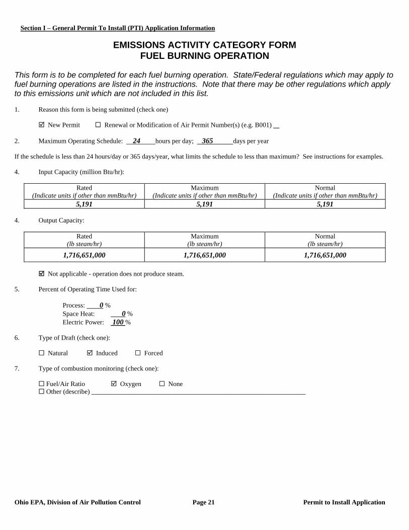
EMISSIONS ACTIVITY CATEGORY FORM
FUEL BURNING OPERATION This form is to be completed for each fuel burning operation. State/Federal regulations which may apply to fuel burning operations are listed in the instructions. Note that there may be other regulations which apply to this emissions unit which are not included in this list. 1. Reason this form is being submitted (check one)
New Permit Renewal or Modification of Air Permit Number(s) (e.g. B001) 2. Maximum Operating Schedule: 24 hours per day; 365 days per year If the schedule is less than 24 hours/day or 365 days/year, what limits the schedule to less than maximum? See instructions for examples. 3. Input Capacity (million Btu/hr):
Rated (Indicate units if other than mmBtu/hr)
Maximum (Indicate units if other than mmBtu/hr)
Normal (Indicate units if other than mmBtu/hr)
5,191 5,191 5,191 4. Output Capacity:
Rated (lb steam/hr)
Maximum (lb steam/hr)
Normal (lb steam/hr)
1,716,651,000 1,716,651,000 1,716,651,000
Not applicable - operation does not produce steam. 5. Percent of Operating Time Used for: Process: 0 %
Space Heat: 0 % Electric Power: 100 %
6. Type of Draft (check one):
Natural Induced Forced 7. Type of combustion monitoring (check one):
Fuel/Air Ratio Oxygen None Other (describe) ________________________________________________________________
Section I – General Permit To Install (PTI) Application Information
Ohio EPA, Division of Air Pollution Control Page 14 Permit to Install Application
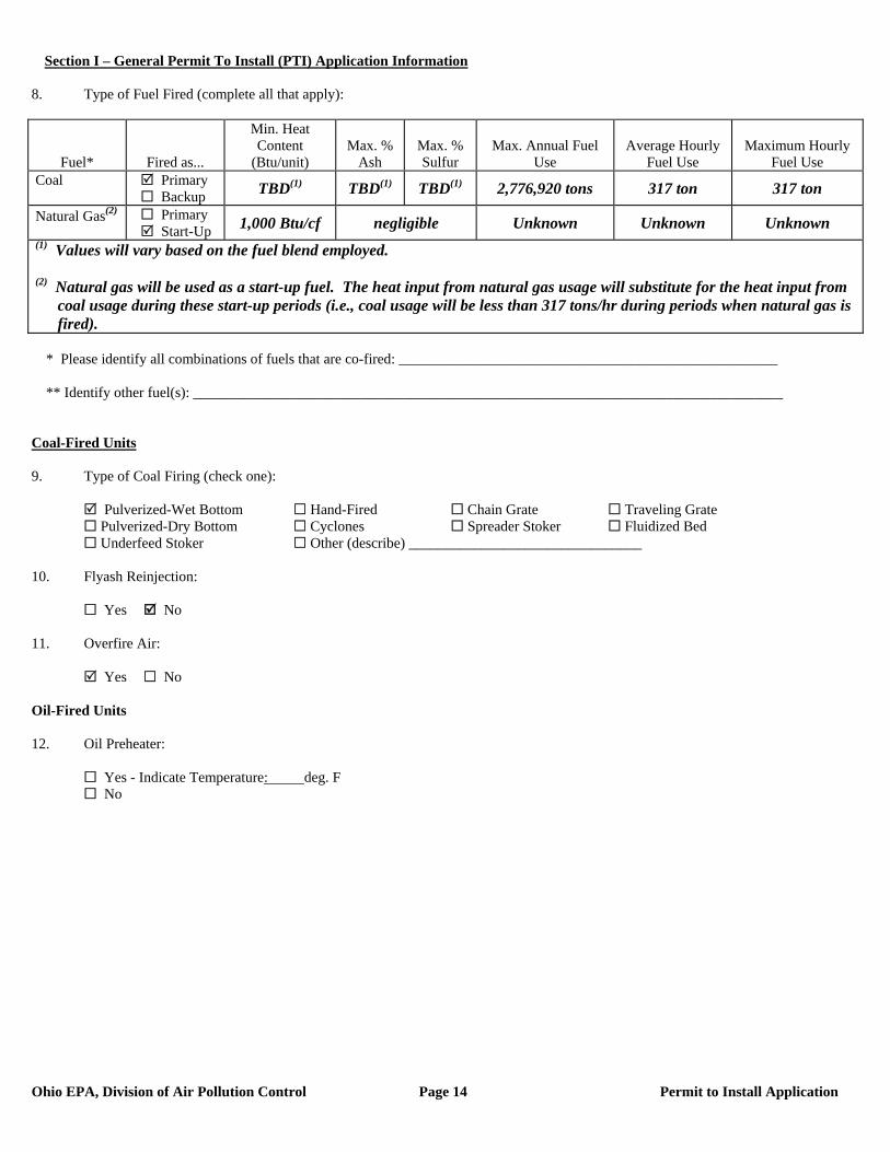
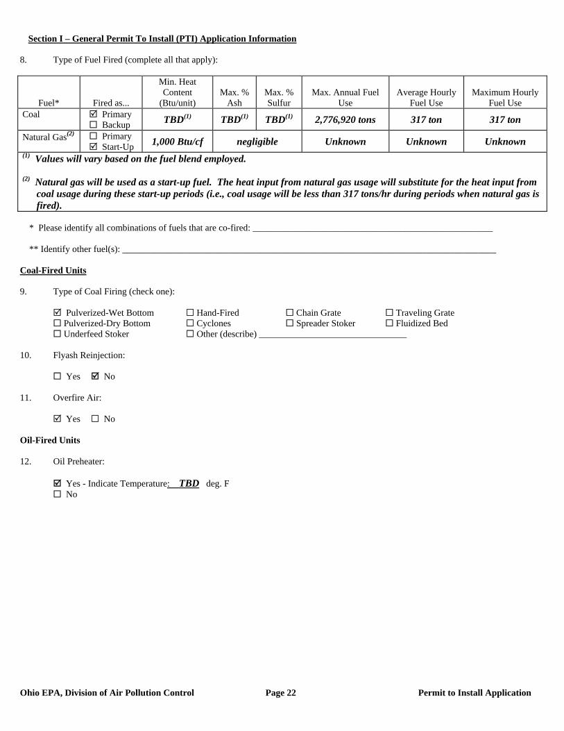
8. Type of Fuel Fired (complete all that apply):
Fuel* Fired as...
Min. Heat Content
(Btu/unit) Max. %
Ash Max. % Sulfur
Max. Annual Fuel Use
Average Hourly Fuel Use
Maximum Hourly Fuel Use
Coal Primary Backup TBD(1) TBD(1) TBD(1) 2,776,920 tons 317 ton 317 ton
Natural Gas(2) Primary Start-Up 1,000 Btu/cf negligible Unknown Unknown Unknown
(1) Values will vary based on the fuel blend employed. (2) Natural gas will be used as a start-up fuel. The heat input from natural gas usage will substitute for the heat input from
coal usage during these start-up periods (i.e., coal usage will be less than 317 tons/hr during periods when natural gas is fired).
* Please identify all combinations of fuels that are co-fired: ____________________________________________________ ** Identify other fuel(s): _________________________________________________________________________________ Coal-Fired Units 9. Type of Coal Firing (check one):
Pulverized-Wet Bottom Hand-Fired Chain Grate Traveling Grate Pulverized-Dry Bottom Cyclones Spreader Stoker Fluidized Bed Underfeed Stoker Other (describe) ________________________________
10. Flyash Reinjection:
Yes No 11. Overfire Air:
Yes No Oil-Fired Units 12. Oil Preheater:
Yes - Indicate Temperature: deg. F No

Section I – General Permit To Install (PTI) Application Information
Ohio EPA, Division of Air Pollution Control Page 15 Permit to Install Application
1. Company identification (name for air contaminant source for which you are applying):
B002 – Pulverized Coal-Fired Boiler 2. List all equipment that are part of this air contaminant source: 5,191 mmBtu/hr Pulverized Coal-Fired Boiler 3. Air Contaminant Source Installation or Modification Schedule (must be completed regardless of date of installation or modification): When did/will you begin to install or modify the air contaminant source? (month/year) 2009 When did/will you begin to operate the air contaminant source? (month/year) 2012 OR after issuance of PTI 4. Emissions Information: The following table requests information needed to determine the applicable requirements and the compliance status of this air contaminant source with those requirements. Suggestions for how to estimate emissions may be found in the instructions to the Emissions Activity Category (EAC) forms required with this application. If you need further assistance, contact your Ohio EPA permit representative.
If total potential emissions of HAPs or any Air Toxic is greater than 1 ton/yr, fill in the table for that (those) pollutant(s).
For all other pollutants, if ‘Emissions before controls (max), lb/hr’ multiplied by 24 hours/day is greater than 10 lb/day, fill in the table for that pollutant.
If you have no add-on control equipment, ‘Emissions before controls’ will be the same as ‘Actual emissions’. Annual emissions should be based on operating 8760 hr/yr unless you are requesting operating restrictions to limit
emissions in line #8 or have described inherent limitations below. If you use units other than lb/hr or ton/yr, specify the units used (e.g., gr/dscf, lb/ton charged, lb/MMBtu, ton/12-months). Requested Allowable (ton/yr) is often equivalent to Potential to Emit (PTE) as defined in OAC rule 3745-31-01(HHH) and
OAC rule 3745-77-01(BB).
Pollutant Emissions
Before Controls (max) (lb/hr)
Actual Emissions
(lb/hr)
Actual Emissions (ton/year)
Requested Allowable
(lb/hr)
Requested Allowable (ton/year)
PE/PM10 (filterable) est. 15,600 #78 #341 78 341 PE/PM10 (filterable + condensable) est. 25,800 #129 #566 129 566 Sulfur Dioxide (SO2) 3-hr average est. 24,920 #1,246 NA 1,246 NA SO2 24-hr average est. 19,100 #955 NA 955 NA SO2 30-day average est. 15,580 #779 #3,410 779 3,410 Sulfuric Acid (H2SO4) est. 960 #38.9 #170.5 38.9 170.5 Volatile Organic Compounds (VOC) est. 19 #19 #83.2 19 83.2 Carbon Monoxide (CO) est. 799 #799 #3,501 799 3,501 Nitrogen Oxides (NOx) 3-hr average est. 5,190 #519 NA 519 NA NOx 30-day average est. 3,630 #363 #1,592 363 1,592 HAPs and Air Toxics Refer to the Emission Calculations section of this permit application.
Provide your calculations as an attachment and explain how all process variables and emission factors were selected. Note the emissions factor(s) employed and document the origin. Example: AP-42, Table 4.4-3 (8/97); stack test, Method 5, 4/96; mass balance based on MSDS; etc.
Refer to the Emission Calculations section of this permit application.
Section I – General Permit To Install (PTI) Application Information
Ohio EPA, Division of Air Pollution Control Page 16 Permit to Install Application
5. Does this air contaminant source employ emissions control equipment? Yes – fill out the applicable information below. No – proceed to item #6. Note: Pollutant abbreviations used below: Particulates = PE; Organic Compounds = OC; Sulfur Dioxide = SO2; Nitrogen Oxides = NOX; Carbon Monoxide = CO
Other, describe Low NOx Burners Manufacturer: To Be Determined (TBD) Year installed: Projected 2010 What do you call this control equipment: Low NOx Burners Pollutant(s) controlled: PE OC SO2 NOX CO Other Estimated capture efficiency (%) Not Applicable (NA) Basis for efficiency: None Design control efficiency (%) NA Basis for efficiency: None This is the only control equipment on this air contaminant source If no, this control equipment is: Primary Secondary Parallel List any other air contaminant sources that are also vented to this control equipment: None
Other, describe Overfire Air System Manufacturer: TBD Year installed: Projected 2010 What do you call this control equipment: Overfire Air System Pollutant(s) controlled: PE OC SO2 NOX CO Other Estimated capture efficiency (%) NA Basis for efficiency: NA Design control efficiency (%) NA Basis for efficiency: NA This is the only control equipment on this air contaminant source If no, this control equipment is: Primary Secondary Parallel List any other air contaminant sources that are also vented to this control equipment: None
Other, describe Selective Catalytic Reduction (SCR) System Manufacturer: TBD Year installed: Projected 2010 What do you call this control equipment: Selective Catalytic Reduction (SCR) System Pollutant(s) controlled: PE OC SO2 NOX CO Other Estimated capture efficiency (%) 100 Basis for efficiency: Equipment Design Design control efficiency (%) NA Basis for efficiency: NA This is the only control equipment on this air contaminant source If no, this control equipment is: Primary Secondary Parallel List any other air contaminant sources that are also vented to this control equipment: None

Section I – General Permit To Install (PTI) Application Information
Ohio EPA, Division of Air Pollution Control Page 17 Permit to Install Application
Fabric Filter/Baghouse Manufacturer: TBD Year installed: Projected 2010 What do you call this control equipment: Baghouse Pollutant(s) controlled: PE OC SO2 NOX CO Other Estimated capture efficiency (%) 100 Basis for efficiency: Design Design control efficiency (%) NA Basis for efficiency: Design Operating pressure drop range (inches of water): Minimum: TBD Maximum: TBD Pressure Type: Negative pressure Positive pressure Fabric Cleaning Mechanism: Reverse Air Pulse Jet Shaker Other Lime injection or fabric coating agent used: Type: NA Feed Rate: NA This is the only control equipment on this air contaminant source If no, this control equipment is: Primary Secondary Parallel List any other air contaminant sources that are also vented to this control equipment: None
Wet Scrubber Manufacturer: TBD Year installed: Projected 2010 What do you call this control equipment: Wet Flue Gas Desulfurization (Wet FGD) Pollutant(s) controlled: PE OC SO2 NOX CO Other Estimated capture efficiency (%) 100 Basis for efficiency: Design Design control efficiency (%) NA Basis for efficiency: Design Type: Spray Chamber Packed Bed Impingement Venturi Other Operating pressure drop range (inches of water): Minimum: TBD Maximum: TBD pH range for scrubbing Liquid : Minimum: TBD Maximum: TBD Scrubbing liquid flow rate (gal/min) TBD Is scrubbing liquid recirculating: Yes No Water Supply pressure (Note: for spray chambers only) (psig): TBD This is the only control equipment on this air contaminant source If no, this control equipment is: Primary Secondary Parallel List any other air contaminant sources that are also vented to this control equipment: None
Wet Electrostatic Precipitator Manufacturer: TBD Year installed: Projected 2010 What do you call this control equipment: Wet ESP Pollutant(s) controlled: PE OC SO2 NOX CO Other Sulfuric Acid Mist Estimated capture efficiency (%) 100 Basis for efficiency: Design Design control efficiency (%) NA Basis for efficiency: Design Type: Plate-wire Flat -plate Tubular Wet Other TBD Number of operating fields: TBD This is the only control equipment on this air contaminant source If no, this control equipment is: Primary Secondary Parallel List any other air contaminant sources that are also vented to this control equipment: None
6. Attach a Process or Activity Flow Diagram to this application for each air contaminant source included in this application. The
diagram should indicate their relationships to one another. See the line by line PTI instructions for additional information. A Process Flow Diagram is on the following page.

Section I – General Permit To Install (PTI) Application Information
Ohio EPA, Division of Air Pollution Control Page 18 Permit to Install Application
Wet ESP(for H2SO4 and condensable
PM10 control)
Pulverized Coal-Fired Boiler(B002)
- Low-NOx Burners- Over-Fire Air- Good Combustion
Controls
SCR (for NOx control)
Pulsejet Baghouse(for PM10 control)
Wet FGD(for SO2 control)
Coal
Exhaust Gases
Stack Emissions to Ambient Air
(B002-S)
Main Boiler #2(B002)
Flow Diagram
Flyash for Beneficial Reuse
or Disposal
FGD By-Product (Gypsum or
Ammonium Sulfate) for Beneficial Reuse
or Disposal
Wastewater
Section I – General Permit To Install (PTI) Application Information
Ohio EPA, Division of Air Pollution Control Page 19 Permit to Install Application
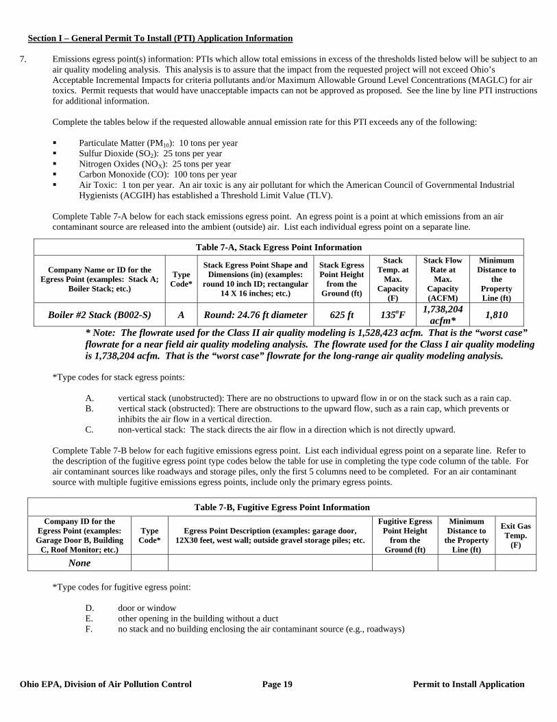
7. Emissions egress point(s) information: PTIs which allow total emissions in excess of the thresholds listed below will be subject to an
air quality modeling analysis. This analysis is to assure that the impact from the requested project will not exceed Ohio’s Acceptable Incremental Impacts for criteria pollutants and/or Maximum Allowable Ground Level Concentrations (MAGLC) for air toxics. Permit requests that would have unacceptable impacts can not be approved as proposed. See the line by line PTI instructions for additional information.
Complete the tables below if the requested allowable annual emission rate for this PTI exceeds any of the following:
Particulate Matter (PM10): 10 tons per year Sulfur Dioxide (SO2): 25 tons per year Nitrogen Oxides (NOX): 25 tons per year Carbon Monoxide (CO): 100 tons per year Air Toxic: 1 ton per year. An air toxic is any air pollutant for which the American Council of Governmental Industrial
Hygienists (ACGIH) has established a Threshold Limit Value (TLV).
Complete Table 7-A below for each stack emissions egress point. An egress point is a point at which emissions from an air contaminant source are released into the ambient (outside) air. List each individual egress point on a separate line.
* Note: The flowrate used for the Class II air quality modeling is 1,528,423 acfm. That is the “worst case” flowrate for a near field air quality modeling analysis. The flowrate used for the Class I air quality modeling is 1,738,204 acfm. That is the “worst case” flowrate for the long-range air quality modeling analysis.
*Type codes for stack egress points:
A. vertical stack (unobstructed): There are no obstructions to upward flow in or on the stack such as a rain cap. B. vertical stack (obstructed): There are obstructions to the upward flow, such as a rain cap, which prevents or
inhibits the air flow in a vertical direction. C. non-vertical stack: The stack directs the air flow in a direction which is not directly upward.
Complete Table 7-B below for each fugitive emissions egress point. List each individual egress point on a separate line. Refer to the description of the fugitive egress point type codes below the table for use in completing the type code column of the table. For air contaminant sources like roadways and storage piles, only the first 5 columns need to be completed. For an air contaminant source with multiple fugitive emissions egress points, include only the primary egress points.
Table 7-B, Fugitive Egress Point Information
Company ID for the Egress Point (examples: Garage Door B, Building
C, Roof Monitor; etc.)
Type Code*
Egress Point Description (examples: garage door, 12X30 feet, west wall; outside gravel storage piles; etc.
Fugitive Egress Point Height
from the Ground (ft)
Minimum Distance to
the Property Line (ft)
Exit Gas Temp.
(F)
None
*Type codes for fugitive egress point:
D. door or window E. other opening in the building without a duct F. no stack and no building enclosing the air contaminant source (e.g., roadways)
Table 7-A, Stack Egress Point Information
Company Name or ID for the Egress Point (examples: Stack A;
Boiler Stack; etc.)
Type Code*
Stack Egress Point Shape and Dimensions (in) (examples:
round 10 inch ID; rectangular 14 X 16 inches; etc.)
Stack Egress Point Height
from the Ground (ft)
Stack Temp. at
Max. Capacity
(F)
Stack Flow Rate at Max.
Capacity (ACFM)
Minimum Distance to
the Property Line (ft)
Boiler #2 Stack (B002-S) A Round: 24.76 ft diameter 625 ft 135oF 1,738,204 acfm* 1,810

Section I – General Permit To Install (PTI) Application Information
Ohio EPA, Division of Air Pollution Control Page 20 Permit to Install Application
Complete Table 7-C below for each Stack Egress Point identified in Table 7-A above. In each case, use the dimensions of the largest nearby building segment or structure. List each individual egress point on a separate line. Use the same Company Name or ID for the Egress Point in Table 7-C that was used in Table 7-A. See the line by line PTI instructions for additional information.
Table 7-C, Egress Point Additional Information
Company ID or Name for the Egress Point Building Height (ft)
Building Width (ft) Building Length (ft)
Boiler #2 Stack (B002-S) 270 502 1,329 8. Request for Federally Enforceable Limits
As part of this permit application, do you wish to propose voluntary restrictions to limit emissions in order to avoid specific requirements list below, (i.e., are you requesting federally enforceable limits to obtain synthetic minor status)?
Yes No Not Sure – Please contact me if this affects me.
If yes, why are you requesting federally enforceable limits? Check all that apply. a. to avoid being a “major source” (see OAC rule 3745-77-01(W)) b. to avoid being a “major MACT source” (see OAC rule 3745-31-01(QQ)) c. to avoid being a “major modification” (see OAC rule 3745-31-01(RR)) d. to avoid being a “major stationary source” (see OAC rule 3745-31-01(SS)) e. to avoid an air dispersion modeling requirement (see Engineering Guide #69) f. to avoid another requirement. Describe: If you checked a., b. or d., please attach a facility-wide potential to emit (PTE) analysis (for each pollutant) and synthetic minor strategy to this application. (See line by line instructions for definition of PTE.) If you checked c., please attach a net emission change analysis to this application.
9. If this air contaminant source utilizes any continuous emissions monitoring equipment for indicating or demonstrating compliance, complete the following table. This does not include continuous parametric monitoring systems.
Company ID for Egress Point Type of Monitor
Applicable Performance Specification
(40 CFR 60, Appendix B) Pollutant(s) Monitored
NOx Analyzer NOx SO2 Analyzer SO2 CO Analyzer CO
CO2/O2 Analyzer CO2/O2 Flow Monitor
40 CFR 75
NA
Boiler #2 Stack
Mercury Monitor 40 CFR Part 60 Subpart Da Mercury 10. Do you wish to permit this air contaminant source as a portable source, allowing relocation within the state in accordance with OAC
rule 3745-31-03(A)(1)(p) or OAC rule 3745-31-05(F)?
Yes – Note: notification requirements in rules cited above must be followed. No
11. The appropriate Emissions Activity Category (EAC) form(s) must be completed and attached for each air contaminant source. At
least one complete EAC form must be submitted for each air contaminant source for the application to be considered complete. Refer to the list attached to the PTI instructions. See attached Fuel Burning Operation EAC Form for emission unit B002.
Section I – General Permit To Install (PTI) Application Information
Ohio EPA, Division of Air Pollution Control Page 21 Permit to Install Application
EMISSIONS ACTIVITY CATEGORY FORM
FUEL BURNING OPERATION This form is to be completed for each fuel burning operation. State/Federal regulations which may apply to fuel burning operations are listed in the instructions. Note that there may be other regulations which apply to this emissions unit which are not included in this list. 1. Reason this form is being submitted (check one)
New Permit Renewal or Modification of Air Permit Number(s) (e.g. B001) 2. Maximum Operating Schedule: 24 hours per day; 365 days per year If the schedule is less than 24 hours/day or 365 days/year, what limits the schedule to less than maximum? See instructions for examples. 4. Input Capacity (million Btu/hr):
Rated (Indicate units if other than mmBtu/hr)
Maximum (Indicate units if other than mmBtu/hr)
Normal (Indicate units if other than mmBtu/hr)
5,191 5,191 5,191 4. Output Capacity:
Rated (lb steam/hr)
Maximum (lb steam/hr)
Normal (lb steam/hr)
1,716,651,000 1,716,651,000 1,716,651,000
Not applicable - operation does not produce steam. 5. Percent of Operating Time Used for: Process: 0 %
Space Heat: 0 % Electric Power: 100 %
6. Type of Draft (check one):
Natural Induced Forced 7. Type of combustion monitoring (check one):
Fuel/Air Ratio Oxygen None Other (describe) ________________________________________________________________
Section I – General Permit To Install (PTI) Application Information
Ohio EPA, Division of Air Pollution Control Page 22 Permit to Install Application
8. Type of Fuel Fired (complete all that apply):
Fuel* Fired as...
Min. Heat Content
(Btu/unit) Max. %
Ash Max. % Sulfur
Max. Annual Fuel Use
Average Hourly Fuel Use
Maximum Hourly Fuel Use
Coal Primary Backup TBD(1) TBD(1) TBD(1) 2,776,920 tons 317 ton 317 ton
Natural Gas(2) Primary Start-Up 1,000 Btu/cf negligible Unknown Unknown Unknown
(1) Values will vary based on the fuel blend employed. (2) Natural gas will be used as a start-up fuel. The heat input from natural gas usage will substitute for the heat input from
coal usage during these start-up periods (i.e., coal usage will be less than 317 tons/hr during periods when natural gas is fired).
* Please identify all combinations of fuels that are co-fired: ____________________________________________________ ** Identify other fuel(s): _________________________________________________________________________________ Coal-Fired Units 9. Type of Coal Firing (check one):
Pulverized-Wet Bottom Hand-Fired Chain Grate Traveling Grate Pulverized-Dry Bottom Cyclones Spreader Stoker Fluidized Bed Underfeed Stoker Other (describe) ________________________________
10. Flyash Reinjection:
Yes No 11. Overfire Air:
Yes No Oil-Fired Units 12. Oil Preheater:
Yes - Indicate Temperature: TBD deg. F No
Section I – General Permit To Install (PTI) Application Information
Ohio EPA, Division of Air Pollution Control Page 23 Permit to Install Application
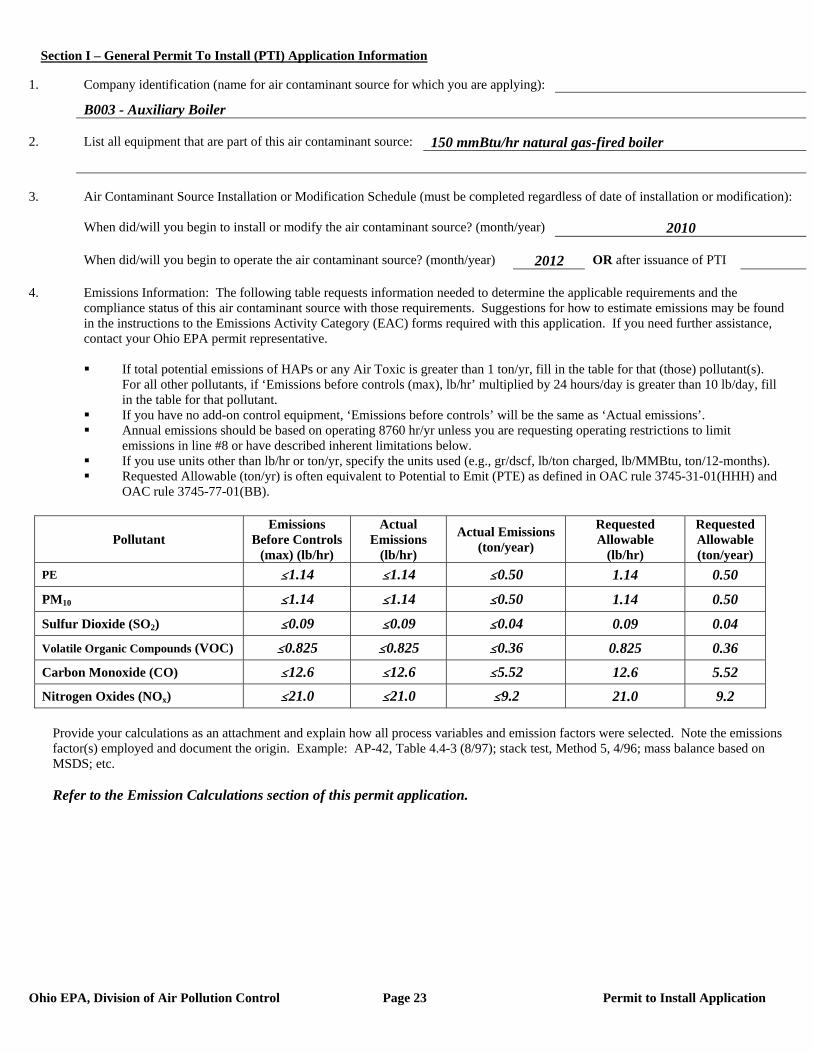
1. Company identification (name for air contaminant source for which you are applying):
B003 - Auxiliary Boiler 2. List all equipment that are part of this air contaminant source: 150 mmBtu/hr natural gas-fired boiler 3. Air Contaminant Source Installation or Modification Schedule (must be completed regardless of date of installation or modification): When did/will you begin to install or modify the air contaminant source? (month/year) 2010 When did/will you begin to operate the air contaminant source? (month/year) 2012 OR after issuance of PTI 4. Emissions Information: The following table requests information needed to determine the applicable requirements and the compliance status of this air contaminant source with those requirements. Suggestions for how to estimate emissions may be found in the instructions to the Emissions Activity Category (EAC) forms required with this application. If you need further assistance, contact your Ohio EPA permit representative.
If total potential emissions of HAPs or any Air Toxic is greater than 1 ton/yr, fill in the table for that (those) pollutant(s).
For all other pollutants, if ‘Emissions before controls (max), lb/hr’ multiplied by 24 hours/day is greater than 10 lb/day, fill in the table for that pollutant.
If you have no add-on control equipment, ‘Emissions before controls’ will be the same as ‘Actual emissions’. Annual emissions should be based on operating 8760 hr/yr unless you are requesting operating restrictions to limit
emissions in line #8 or have described inherent limitations below. If you use units other than lb/hr or ton/yr, specify the units used (e.g., gr/dscf, lb/ton charged, lb/MMBtu, ton/12-months). Requested Allowable (ton/yr) is often equivalent to Potential to Emit (PTE) as defined in OAC rule 3745-31-01(HHH) and
OAC rule 3745-77-01(BB).
Pollutant Emissions
Before Controls (max) (lb/hr)
Actual Emissions
(lb/hr)
Actual Emissions (ton/year)
Requested Allowable
(lb/hr)
Requested Allowable (ton/year)
PE #1.14 #1.14 #0.50 1.14 0.50
PM10 #1.14 #1.14 #0.50 1.14 0.50
Sulfur Dioxide (SO2) #0.09 #0.09 #0.04 0.09 0.04 Volatile Organic Compounds (VOC) #0.825 #0.825 #0.36 0.825 0.36 Carbon Monoxide (CO) #12.6 #12.6 #5.52 12.6 5.52 Nitrogen Oxides (NOx) #21.0 #21.0 #9.2 21.0 9.2
Provide your calculations as an attachment and explain how all process variables and emission factors were selected. Note the emissions factor(s) employed and document the origin. Example: AP-42, Table 4.4-3 (8/97); stack test, Method 5, 4/96; mass balance based on MSDS; etc.
Refer to the Emission Calculations section of this permit application.
Section I – General Permit To Install (PTI) Application Information
Ohio EPA, Division of Air Pollution Control Page 24 Permit to Install Application
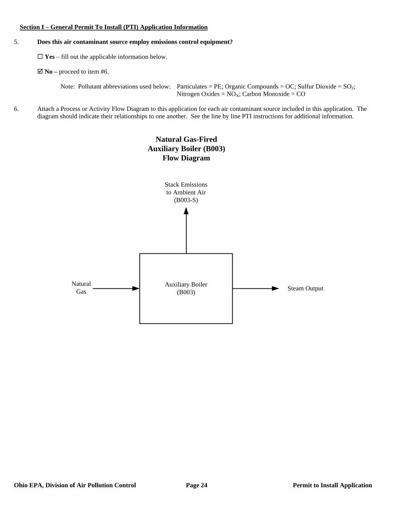
5. Does this air contaminant source employ emissions control equipment? Yes – fill out the applicable information below. No – proceed to item #6. Note: Pollutant abbreviations used below: Particulates = PE; Organic Compounds = OC; Sulfur Dioxide = SO2; Nitrogen Oxides = NOX; Carbon Monoxide = CO 6. Attach a Process or Activity Flow Diagram to this application for each air contaminant source included in this application. The
diagram should indicate their relationships to one another. See the line by line PTI instructions for additional information.
Auxiliary Boiler(B003) Steam Output
Stack Emissions to Ambient Air
(B003-S)
Natural Gas
Natural Gas-Fired Auxiliary Boiler (B003)
Flow Diagram
Section I – General Permit To Install (PTI) Application Information
Ohio EPA, Division of Air Pollution Control Page 25 Permit to Install Application
7. Emissions egress point(s) information: PTIs which allow total emissions in excess of the thresholds listed below will be subject to an
air quality modeling analysis. This analysis is to assure that the impact from the requested project will not exceed Ohio’s Acceptable Incremental Impacts for criteria pollutants and/or Maximum Allowable Ground Level Concentrations (MAGLC) for air toxics. Permit requests that would have unacceptable impacts can not be approved as proposed. See the line by line PTI instructions for additional information.
Complete the tables below if the requested allowable annual emission rate for this PTI exceeds any of the following:
Particulate Matter (PM10): 10 tons per year Sulfur Dioxide (SO2): 25 tons per year Nitrogen Oxides (NOX): 25 tons per year Carbon Monoxide (CO): 100 tons per year Air Toxic: 1 ton per year. An air toxic is any air pollutant for which the American Council of Governmental Industrial
Hygienists (ACGIH) has established a Threshold Limit Value (TLV).
Complete Table 7-A below for each stack emissions egress point. An egress point is a point at which emissions from an air contaminant source are released into the ambient (outside) air. List each individual egress point on a separate line.
*Type codes for stack egress points:
A. vertical stack (unobstructed): There are no obstructions to upward flow in or on the stack such as a rain cap. B. vertical stack (obstructed): There are obstructions to the upward flow, such as a rain cap, which prevents or
inhibits the air flow in a vertical direction. C. non-vertical stack: The stack directs the air flow in a direction which is not directly upward.
Complete Table 7-B below for each fugitive emissions egress point. List each individual egress point on a separate line. Refer to the description of the fugitive egress point type codes below the table for use in completing the type code column of the table. For air contaminant sources like roadways and storage piles, only the first 5 columns need to be completed. For an air contaminant source with multiple fugitive emissions egress points, include only the primary egress points.
Table 7-B, Fugitive Egress Point Information
Company ID for the Egress Point (examples: Garage Door B, Building
C, Roof Monitor; etc.)
Type Code*
Egress Point Description (examples: garage door, 12X30 feet, west wall; outside gravel storage piles; etc.
Fugitive Egress Point Height
from the Ground (ft)
Minimum Distance to
the Property Line (ft)
Exit Gas Temp.
(F)
None
*Type codes for fugitive egress point:
D. door or window E. other opening in the building without a duct F. no stack and no building enclosing the air contaminant source (e.g., roadways)
Table 7-A, Stack Egress Point Information
Company Name or ID for the Egress Point (examples: Stack A;
Boiler Stack; etc.)
Type Code*
Stack Egress Point Shape and Dimensions (in) (examples:
round 10 inch ID; rectangular 14 X 16 inches; etc.)
Stack Egress Point Height
from the Ground (ft)
Stack Temp. at
Max. Capacity
(F)
Stack Flow Rate at Max.
Capacity (ACFM)
Minimum Distance to
the Property Line (ft)
Auxiliary Boiler Stack (B003-S) A Round: 4 ft diameter 277 300 45,000 1,075
Section I – General Permit To Install (PTI) Application Information
Ohio EPA, Division of Air Pollution Control Page 26 Permit to Install Application
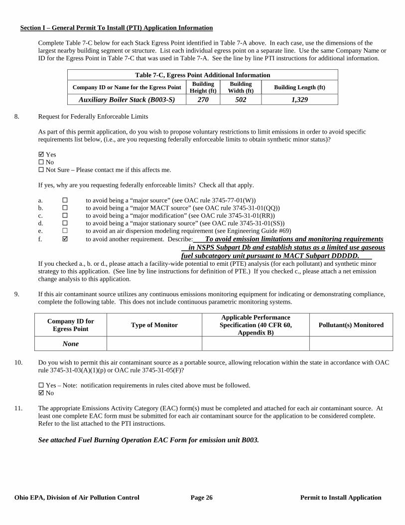
Complete Table 7-C below for each Stack Egress Point identified in Table 7-A above. In each case, use the dimensions of the largest nearby building segment or structure. List each individual egress point on a separate line. Use the same Company Name or ID for the Egress Point in Table 7-C that was used in Table 7-A. See the line by line PTI instructions for additional information.
Table 7-C, Egress Point Additional Information
Company ID or Name for the Egress Point Building Height (ft)
Building Width (ft) Building Length (ft)
Auxiliary Boiler Stack (B003-S) 270 502 1,329 8. Request for Federally Enforceable Limits
As part of this permit application, do you wish to propose voluntary restrictions to limit emissions in order to avoid specific requirements list below, (i.e., are you requesting federally enforceable limits to obtain synthetic minor status)?
Yes No Not Sure – Please contact me if this affects me.
If yes, why are you requesting federally enforceable limits? Check all that apply. a. to avoid being a “major source” (see OAC rule 3745-77-01(W)) b. to avoid being a “major MACT source” (see OAC rule 3745-31-01(QQ)) c. to avoid being a “major modification” (see OAC rule 3745-31-01(RR)) d. to avoid being a “major stationary source” (see OAC rule 3745-31-01(SS)) e. to avoid an air dispersion modeling requirement (see Engineering Guide #69) f. to avoid another requirement. Describe: To avoid emission limitations and monitoring requirements
in NSPS Subpart Db and establish status as a limited use gaseous fuel subcategory unit pursuant to MACT Subpart DDDDD.
If you checked a., b. or d., please attach a facility-wide potential to emit (PTE) analysis (for each pollutant) and synthetic minor strategy to this application. (See line by line instructions for definition of PTE.) If you checked c., please attach a net emission change analysis to this application.
9. If this air contaminant source utilizes any continuous emissions monitoring equipment for indicating or demonstrating compliance, complete the following table. This does not include continuous parametric monitoring systems.
Company ID for Egress Point Type of Monitor
Applicable Performance Specification (40 CFR 60,
Appendix B) Pollutant(s) Monitored
None
10. Do you wish to permit this air contaminant source as a portable source, allowing relocation within the state in accordance with OAC
rule 3745-31-03(A)(1)(p) or OAC rule 3745-31-05(F)?
Yes – Note: notification requirements in rules cited above must be followed. No
11. The appropriate Emissions Activity Category (EAC) form(s) must be completed and attached for each air contaminant source. At
least one complete EAC form must be submitted for each air contaminant source for the application to be considered complete. Refer to the list attached to the PTI instructions. See attached Fuel Burning Operation EAC Form for emission unit B003.
Section I – General Permit To Install (PTI) Application Information
Ohio EPA, Division of Air Pollution Control Page 27 Permit to Install Application
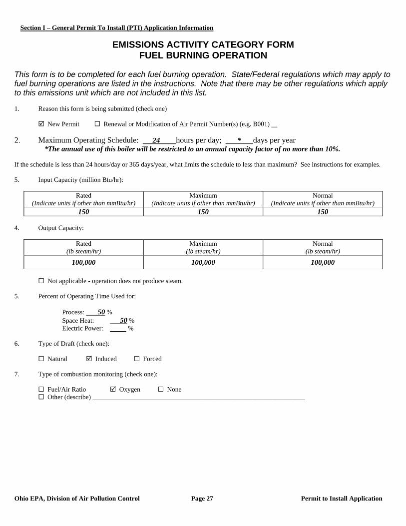
EMISSIONS ACTIVITY CATEGORY FORM
FUEL BURNING OPERATION This form is to be completed for each fuel burning operation. State/Federal regulations which may apply to fuel burning operations are listed in the instructions. Note that there may be other regulations which apply to this emissions unit which are not included in this list. 1. Reason this form is being submitted (check one)
New Permit Renewal or Modification of Air Permit Number(s) (e.g. B001) 2. Maximum Operating Schedule: 24 hours per day; * days per year *The annual use of this boiler will be restricted to an annual capacity factor of no more than 10%. If the schedule is less than 24 hours/day or 365 days/year, what limits the schedule to less than maximum? See instructions for examples. 5. Input Capacity (million Btu/hr):
Rated (Indicate units if other than mmBtu/hr)
Maximum (Indicate units if other than mmBtu/hr)
Normal (Indicate units if other than mmBtu/hr)
150 150 150 4. Output Capacity:
Rated (lb steam/hr)
Maximum (lb steam/hr)
Normal (lb steam/hr)
100,000 100,000 100,000
Not applicable - operation does not produce steam. 5. Percent of Operating Time Used for: Process: 50 %
Space Heat: 50 % Electric Power: %
6. Type of Draft (check one):
Natural Induced Forced 7. Type of combustion monitoring (check one):
Fuel/Air Ratio Oxygen None Other (describe) ________________________________________________________________
Section I – General Permit To Install (PTI) Application Information
Ohio EPA, Division of Air Pollution Control Page 28 Permit to Install Application
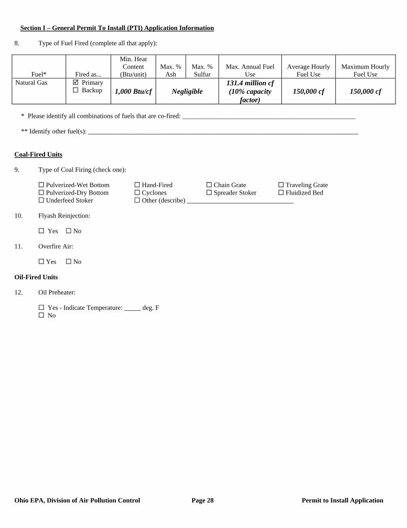
8. Type of Fuel Fired (complete all that apply):
Fuel* Fired as...
Min. Heat Content
(Btu/unit) Max. %
Ash Max. % Sulfur
Max. Annual Fuel Use
Average Hourly Fuel Use
Maximum Hourly Fuel Use
Natural Gas Primary Backup 1,000 Btu/cf Negligible
131.4 million cf (10% capacity
factor) 150,000 cf 150,000 cf
* Please identify all combinations of fuels that are co-fired: ____________________________________________________ ** Identify other fuel(s): _________________________________________________________________________________ Coal-Fired Units 9. Type of Coal Firing (check one):
Pulverized-Wet Bottom Hand-Fired Chain Grate Traveling Grate Pulverized-Dry Bottom Cyclones Spreader Stoker Fluidized Bed Underfeed Stoker Other (describe) ________________________________
10. Flyash Reinjection:
Yes No 11. Overfire Air:
Yes No Oil-Fired Units 12. Oil Preheater:
Yes - Indicate Temperature: _____ deg. F No
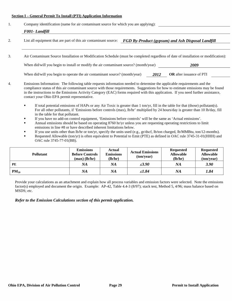
Section I – General Permit To Install (PTI) Application Information
Ohio EPA, Division of Air Pollution Control Page 29 Permit to Install Application
1. Company identification (name for air contaminant source for which you are applying):
F001- Landfill 2. List all equipment that are part of this air contaminant source: FGD By-Product (gypsum) and Ash Disposal Landfill 3. Air Contaminant Source Installation or Modification Schedule (must be completed regardless of date of installation or modification): When did/will you begin to install or modify the air contaminant source? (month/year) 2009 When did/will you begin to operate the air contaminant source? (month/year) 2012 OR after issuance of PTI 4. Emissions Information: The following table requests information needed to determine the applicable requirements and the compliance status of this air contaminant source with those requirements. Suggestions for how to estimate emissions may be found in the instructions to the Emissions Activity Category (EAC) forms required with this application. If you need further assistance, contact your Ohio EPA permit representative.
If total potential emissions of HAPs or any Air Toxic is greater than 1 ton/yr, fill in the table for that (those) pollutant(s).
For all other pollutants, if ‘Emissions before controls (max), lb/hr’ multiplied by 24 hours/day is greater than 10 lb/day, fill in the table for that pollutant.
If you have no add-on control equipment, ‘Emissions before controls’ will be the same as ‘Actual emissions’. Annual emissions should be based on operating 8760 hr/yr unless you are requesting operating restrictions to limit
emissions in line #8 or have described inherent limitations below. If you use units other than lb/hr or ton/yr, specify the units used (e.g., gr/dscf, lb/ton charged, lb/MMBtu, ton/12-months). Requested Allowable (ton/yr) is often equivalent to Potential to Emit (PTE) as defined in OAC rule 3745-31-01(HHH) and
OAC rule 3745-77-01(BB).
Pollutant Emissions
Before Controls (max) (lb/hr)
Actual Emissions
(lb/hr)
Actual Emissions (ton/year)
Requested Allowable
(lb/hr)
Requested Allowable (ton/year)
PE NA NA #3.90 NA 3.90
PM10 NA NA #1.84 NA 1.84
Provide your calculations as an attachment and explain how all process variables and emission factors were selected. Note the emissions factor(s) employed and document the origin. Example: AP-42, Table 4.4-3 (8/97); stack test, Method 5, 4/96; mass balance based on MSDS; etc.
Refer to the Emission Calculations section of this permit application.
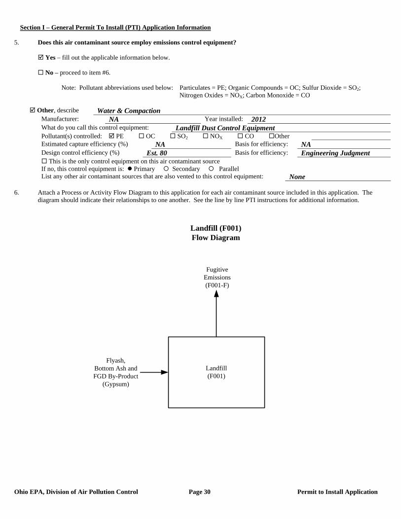
Section I – General Permit To Install (PTI) Application Information
Ohio EPA, Division of Air Pollution Control Page 30 Permit to Install Application
5. Does this air contaminant source employ emissions control equipment? Yes – fill out the applicable information below. No – proceed to item #6. Note: Pollutant abbreviations used below: Particulates = PE; Organic Compounds = OC; Sulfur Dioxide = SO2; Nitrogen Oxides = NOX; Carbon Monoxide = CO
Other, describe Water & Compaction Manufacturer: NA Year installed: 2012 What do you call this control equipment: Landfill Dust Control Equipment Pollutant(s) controlled: PE OC SO2 NOX CO Other Estimated capture efficiency (%) NA Basis for efficiency: NA Design control efficiency (%) Est. 80 Basis for efficiency: Engineering Judgment This is the only control equipment on this air contaminant source If no, this control equipment is: Primary Secondary Parallel List any other air contaminant sources that are also vented to this control equipment: None
6. Attach a Process or Activity Flow Diagram to this application for each air contaminant source included in this application. The
diagram should indicate their relationships to one another. See the line by line PTI instructions for additional information.
FugitiveEmissions(F001-F)
Flyash,Bottom Ash and FGD By-Product
(Gypsum)
Landfill (F001)Flow Diagram
Landfill(F001)
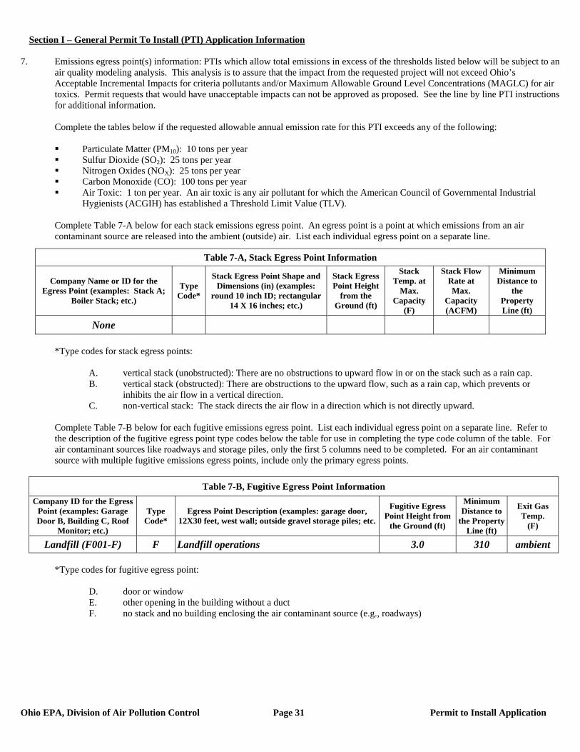
Section I – General Permit To Install (PTI) Application Information
Ohio EPA, Division of Air Pollution Control Page 31 Permit to Install Application
7. Emissions egress point(s) information: PTIs which allow total emissions in excess of the thresholds listed below will be subject to an
air quality modeling analysis. This analysis is to assure that the impact from the requested project will not exceed Ohio’s Acceptable Incremental Impacts for criteria pollutants and/or Maximum Allowable Ground Level Concentrations (MAGLC) for air toxics. Permit requests that would have unacceptable impacts can not be approved as proposed. See the line by line PTI instructions for additional information.
Complete the tables below if the requested allowable annual emission rate for this PTI exceeds any of the following:
Particulate Matter (PM10): 10 tons per year Sulfur Dioxide (SO2): 25 tons per year Nitrogen Oxides (NOX): 25 tons per year Carbon Monoxide (CO): 100 tons per year Air Toxic: 1 ton per year. An air toxic is any air pollutant for which the American Council of Governmental Industrial
Hygienists (ACGIH) has established a Threshold Limit Value (TLV).
Complete Table 7-A below for each stack emissions egress point. An egress point is a point at which emissions from an air contaminant source are released into the ambient (outside) air. List each individual egress point on a separate line.
*Type codes for stack egress points:
A. vertical stack (unobstructed): There are no obstructions to upward flow in or on the stack such as a rain cap. B. vertical stack (obstructed): There are obstructions to the upward flow, such as a rain cap, which prevents or
inhibits the air flow in a vertical direction. C. non-vertical stack: The stack directs the air flow in a direction which is not directly upward.
Complete Table 7-B below for each fugitive emissions egress point. List each individual egress point on a separate line. Refer to the description of the fugitive egress point type codes below the table for use in completing the type code column of the table. For air contaminant sources like roadways and storage piles, only the first 5 columns need to be completed. For an air contaminant source with multiple fugitive emissions egress points, include only the primary egress points.
Table 7-B, Fugitive Egress Point Information
Company ID for the Egress Point (examples: Garage Door B, Building C, Roof
Monitor; etc.)
Type Code*
Egress Point Description (examples: garage door, 12X30 feet, west wall; outside gravel storage piles; etc.
Fugitive Egress Point Height from
the Ground (ft)
Minimum Distance to
the Property Line (ft)
Exit Gas Temp.
(F)
Landfill (F001-F) F Landfill operations 3.0 310 ambient
*Type codes for fugitive egress point:
D. door or window E. other opening in the building without a duct F. no stack and no building enclosing the air contaminant source (e.g., roadways)
Table 7-A, Stack Egress Point Information
Company Name or ID for the Egress Point (examples: Stack A;
Boiler Stack; etc.)
Type Code*
Stack Egress Point Shape and Dimensions (in) (examples:
round 10 inch ID; rectangular 14 X 16 inches; etc.)
Stack Egress Point Height
from the Ground (ft)
Stack Temp. at
Max. Capacity
(F)
Stack Flow Rate at Max.
Capacity (ACFM)
Minimum Distance to
the Property Line (ft)
None
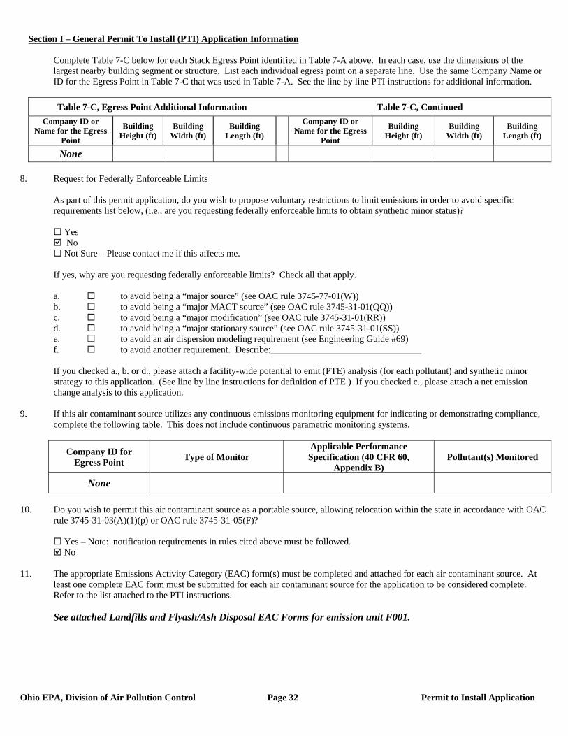
Section I – General Permit To Install (PTI) Application Information
Ohio EPA, Division of Air Pollution Control Page 32 Permit to Install Application
Complete Table 7-C below for each Stack Egress Point identified in Table 7-A above. In each case, use the dimensions of the largest nearby building segment or structure. List each individual egress point on a separate line. Use the same Company Name or ID for the Egress Point in Table 7-C that was used in Table 7-A. See the line by line PTI instructions for additional information.
Table 7-C, Egress Point Additional Information Table 7-C, Continued
Company ID or Name for the Egress
Point
Building Height (ft)
Building Width (ft)
Building Length (ft)
Company ID or Name for the Egress
Point
Building Height (ft)
Building Width (ft)
Building Length (ft)
None 8. Request for Federally Enforceable Limits
As part of this permit application, do you wish to propose voluntary restrictions to limit emissions in order to avoid specific requirements list below, (i.e., are you requesting federally enforceable limits to obtain synthetic minor status)?
Yes No Not Sure – Please contact me if this affects me.
If yes, why are you requesting federally enforceable limits? Check all that apply. a. to avoid being a “major source” (see OAC rule 3745-77-01(W)) b. to avoid being a “major MACT source” (see OAC rule 3745-31-01(QQ)) c. to avoid being a “major modification” (see OAC rule 3745-31-01(RR)) d. to avoid being a “major stationary source” (see OAC rule 3745-31-01(SS)) e. to avoid an air dispersion modeling requirement (see Engineering Guide #69) f. to avoid another requirement. Describe: If you checked a., b. or d., please attach a facility-wide potential to emit (PTE) analysis (for each pollutant) and synthetic minor strategy to this application. (See line by line instructions for definition of PTE.) If you checked c., please attach a net emission change analysis to this application.
9. If this air contaminant source utilizes any continuous emissions monitoring equipment for indicating or demonstrating compliance, complete the following table. This does not include continuous parametric monitoring systems.
Company ID for Egress Point Type of Monitor
Applicable Performance Specification (40 CFR 60,
Appendix B) Pollutant(s) Monitored
None
10. Do you wish to permit this air contaminant source as a portable source, allowing relocation within the state in accordance with OAC
rule 3745-31-03(A)(1)(p) or OAC rule 3745-31-05(F)?
Yes – Note: notification requirements in rules cited above must be followed. No
11. The appropriate Emissions Activity Category (EAC) form(s) must be completed and attached for each air contaminant source. At
least one complete EAC form must be submitted for each air contaminant source for the application to be considered complete. Refer to the list attached to the PTI instructions. See attached Landfills and Flyash/Ash Disposal EAC Forms for emission unit F001.
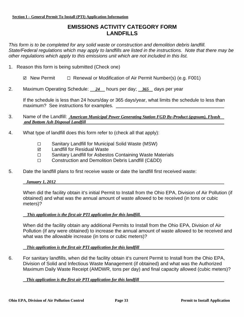
Section I – General Permit To Install (PTI) Application Information
Ohio EPA, Division of Air Pollution Control Page 33 Permit to Install Application
EMISSIONS ACTIVITY CATEGORY FORM
LANDFILLS This form is to be completed for any solid waste or construction and demolition debris landfill. State/Federal regulations which may apply to landfills are listed in the instructions. Note that there may be other regulations which apply to this emissions unit which are not included in this list. 1. Reason this form is being submitted (Check one)
New Permit Renewal or Modification of Air Permit Number(s) (e.g. F001) 2. Maximum Operating Schedule: 24 hours per day; 365 days per year
If the schedule is less than 24 hours/day or 365 days/year, what limits the schedule to less than maximum? See instructions for examples.
3. Name of the Landfill: American Municipal Power Generating Station FGD By-Product (gypsum), Flyash and Bottom Ash Disposal Landfill 4. What type of landfill does this form refer to (check all that apply):
Sanitary Landfill for Municipal Solid Waste (MSW) Landfill for Residual Waste Sanitary Landfill for Asbestos Containing Waste Materials Construction and Demolition Debris Landfill (C&DD)
5. Date the landfill plans to first receive waste or date the landfill first received waste: January 1, 2012 When did the facility obtain it=s initial Permit to Install from the Ohio EPA, Division of Air Pollution (if
obtained) and what was the annual amount of waste allowed to be received (in tons or cubic meters)?
This application is the first air PTI application for this landfill.
When did the facility obtain any additional Permits to Install from the Ohio EPA, Division of Air Pollution (if any were obtained) to increase the annual amount of waste allowed to be received and what was the allowable increase (in tons or cubic meters)? This application is the first air PTI application for this landfill
6. For sanitary landfills, when did the facility obtain it=s current Permit to Install from the Ohio EPA,
Division of Solid and Infectious Waste Management (if obtained) and what was the Authorized Maximum Daily Waste Receipt (AMDWR, tons per day) and final capacity allowed (cubic meters)?
This application is the first air PTI application for this landfill
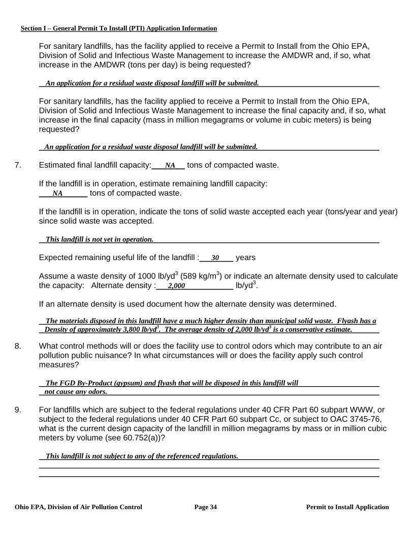
Section I – General Permit To Install (PTI) Application Information
Ohio EPA, Division of Air Pollution Control Page 34 Permit to Install Application
For sanitary landfills, has the facility applied to receive a Permit to Install from the Ohio EPA, Division of Solid and Infectious Waste Management to increase the AMDWR and, if so, what increase in the AMDWR (tons per day) is being requested?
An application for a residual waste disposal landfill will be submitted.
For sanitary landfills, has the facility applied to receive a Permit to Install from the Ohio EPA, Division of Solid and Infectious Waste Management to increase the final capacity and, if so, what increase in the final capacity (mass in million megagrams or volume in cubic meters) is being requested?
An application for a residual waste disposal landfill will be submitted. 7. Estimated final landfill capacity: NA tons of compacted waste.
If the landfill is in operation, estimate remaining landfill capacity: NA tons of compacted waste. If the landfill is in operation, indicate the tons of solid waste accepted each year (tons/year and year) since solid waste was accepted.
This landfill is not yet in operation.
Expected remaining useful life of the landfill : 30 years
Assume a waste density of 1000 lb/yd3 (589 kg/m3) or indicate an alternate density used to calculate the capacity: Alternate density : 2,000 lb/yd3.
If an alternate density is used document how the alternate density was determined.
The materials disposed in this landfill have a much higher density than municipal solid waste. Flyash has a Density of approximately 3,800 lb/yd3. The average density of 2,000 lb/yd3 is a conservative estimate. 8. What control methods will or does the facility use to control odors which may contribute to an air
pollution public nuisance? In what circumstances will or does the facility apply such control measures?
The FGD By-Product (gypsum) and flyash that will be disposed in this landfill will not cause any odors. 9. For landfills which are subject to the federal regulations under 40 CFR Part 60 subpart WWW, or
subject to the federal regulations under 40 CFR Part 60 subpart Cc, or subject to OAC 3745-76, what is the current design capacity of the landfill in million megagrams by mass or in million cubic meters by volume (see 60.752(a))?
This landfill is not subject to any of the referenced regulations.
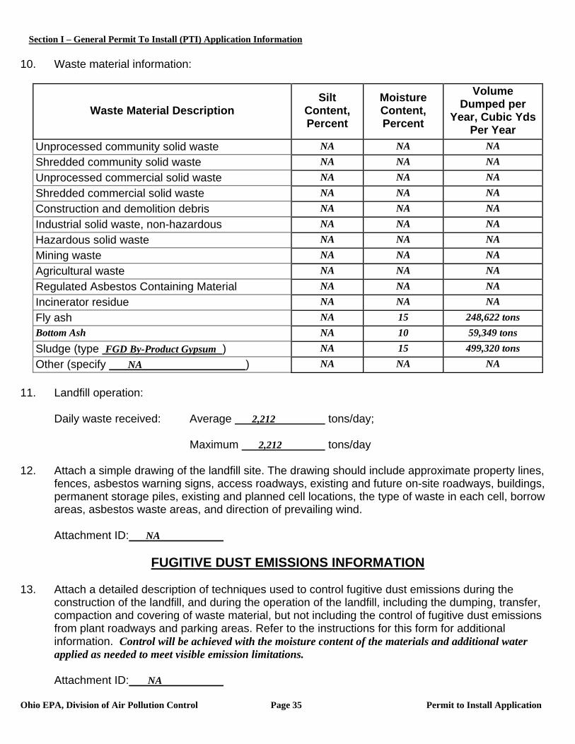
Section I – General Permit To Install (PTI) Application Information
Ohio EPA, Division of Air Pollution Control Page 35 Permit to Install Application
10. Waste material information:
Waste Material Description Silt
Content, Percent
Moisture Content, Percent
Volume Dumped per
Year, Cubic Yds Per Year
Unprocessed community solid waste NA NA NA Shredded community solid waste NA NA NA Unprocessed commercial solid waste NA NA NA Shredded commercial solid waste NA NA NA Construction and demolition debris NA NA NA Industrial solid waste, non-hazardous NA NA NA Hazardous solid waste NA NA NA Mining waste NA NA NA Agricultural waste NA NA NA Regulated Asbestos Containing Material NA NA NA Incinerator residue NA NA NA Fly ash NA 15 248,622 tons Bottom Ash NA 10 59,349 tons Sludge (type FGD By-Product Gypsum ) NA 15 499,320 tons Other (specify NA ) NA NA NA
11. Landfill operation:
Daily waste received: Average 2,212 tons/day;
Maximum 2,212 tons/day 12. Attach a simple drawing of the landfill site. The drawing should include approximate property lines,
fences, asbestos warning signs, access roadways, existing and future on-site roadways, buildings, permanent storage piles, existing and planned cell locations, the type of waste in each cell, borrow areas, asbestos waste areas, and direction of prevailing wind.
Attachment ID: NA
FUGITIVE DUST EMISSIONS INFORMATION
13. Attach a detailed description of techniques used to control fugitive dust emissions during the
construction of the landfill, and during the operation of the landfill, including the dumping, transfer, compaction and covering of waste material, but not including the control of fugitive dust emissions from plant roadways and parking areas. Refer to the instructions for this form for additional information. Control will be achieved with the moisture content of the materials and additional water applied as needed to meet visible emission limitations.
Attachment ID: NA
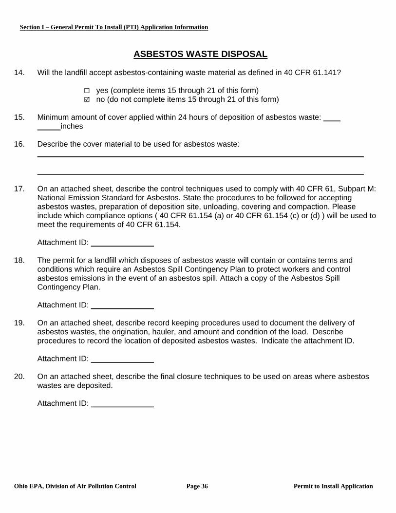
Section I – General Permit To Install (PTI) Application Information
Ohio EPA, Division of Air Pollution Control Page 36 Permit to Install Application
ASBESTOS WASTE DISPOSAL 14. Will the landfill accept asbestos-containing waste material as defined in 40 CFR 61.141?
yes (complete items 15 through 21 of this form) no (do not complete items 15 through 21 of this form)
15. Minimum amount of cover applied within 24 hours of deposition of asbestos waste:
inches 16. Describe the cover material to be used for asbestos waste: 17. On an attached sheet, describe the control techniques used to comply with 40 CFR 61, Subpart M:
National Emission Standard for Asbestos. State the procedures to be followed for accepting asbestos wastes, preparation of deposition site, unloading, covering and compaction. Please include which compliance options ( 40 CFR 61.154 (a) or 40 CFR 61.154 (c) or (d) ) will be used to meet the requirements of 40 CFR 61.154.
Attachment ID:
18. The permit for a landfill which disposes of asbestos waste will contain or contains terms and
conditions which require an Asbestos Spill Contingency Plan to protect workers and control asbestos emissions in the event of an asbestos spill. Attach a copy of the Asbestos Spill Contingency Plan.
Attachment ID:
19. On an attached sheet, describe record keeping procedures used to document the delivery of
asbestos wastes, the origination, hauler, and amount and condition of the load. Describe procedures to record the location of deposited asbestos wastes. Indicate the attachment ID.
Attachment ID:
20. On an attached sheet, describe the final closure techniques to be used on areas where asbestos
wastes are deposited.
Attachment ID:
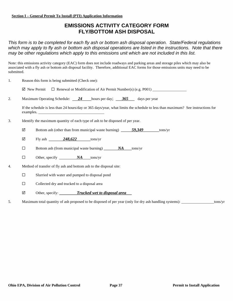
Section I – General Permit To Install (PTI) Application Information
Ohio EPA, Division of Air Pollution Control Page 37 Permit to Install Application
EMISSIONS ACTIVITY CATEGORY FORM
FLY/BOTTOM ASH DISPOSAL This form is to be completed for each fly ash or bottom ash disposal operation. State/Federal regulations which may apply to fly ash or bottom ash disposal operations are listed in the instructions. Note that there may be other regulations which apply to this emissions unit which are not included in this list. Note: this emissions activity category (EAC) form does not include roadways and parking areas and storage piles which may also be associated with a fly ash or bottom ash disposal facility. Therefore, additional EAC forms for those emissions units may need to be submitted. 1. Reason this form is being submitted (Check one): New Permit Renewal or Modification of Air Permit Number(s) (e.g. P001) 2. Maximum Operating Schedule: 24 hours per day; 365 days per year
If the schedule is less than 24 hours/day or 365 days/year, what limits the schedule to less than maximum? See instructions for examples.
3. Identify the maximum quantity of each type of ash to be disposed of per year.
Bottom ash (other than from municipal waste burning) 59,349 tons/yr
Fly ash 248,622 tons/yr
Bottom ash (from municipal waste burning) NA tons/yr
Other, specify NA tons/yr 4. Method of transfer of fly ash and bottom ash to the disposal site:
Slurried with water and pumped to disposal pond
Collected dry and trucked to a disposal area
Other, specify: Trucked wet to disposal area 5. Maximum total quantity of ash proposed to be disposed of per year (only for dry ash handling systems): tons/yr
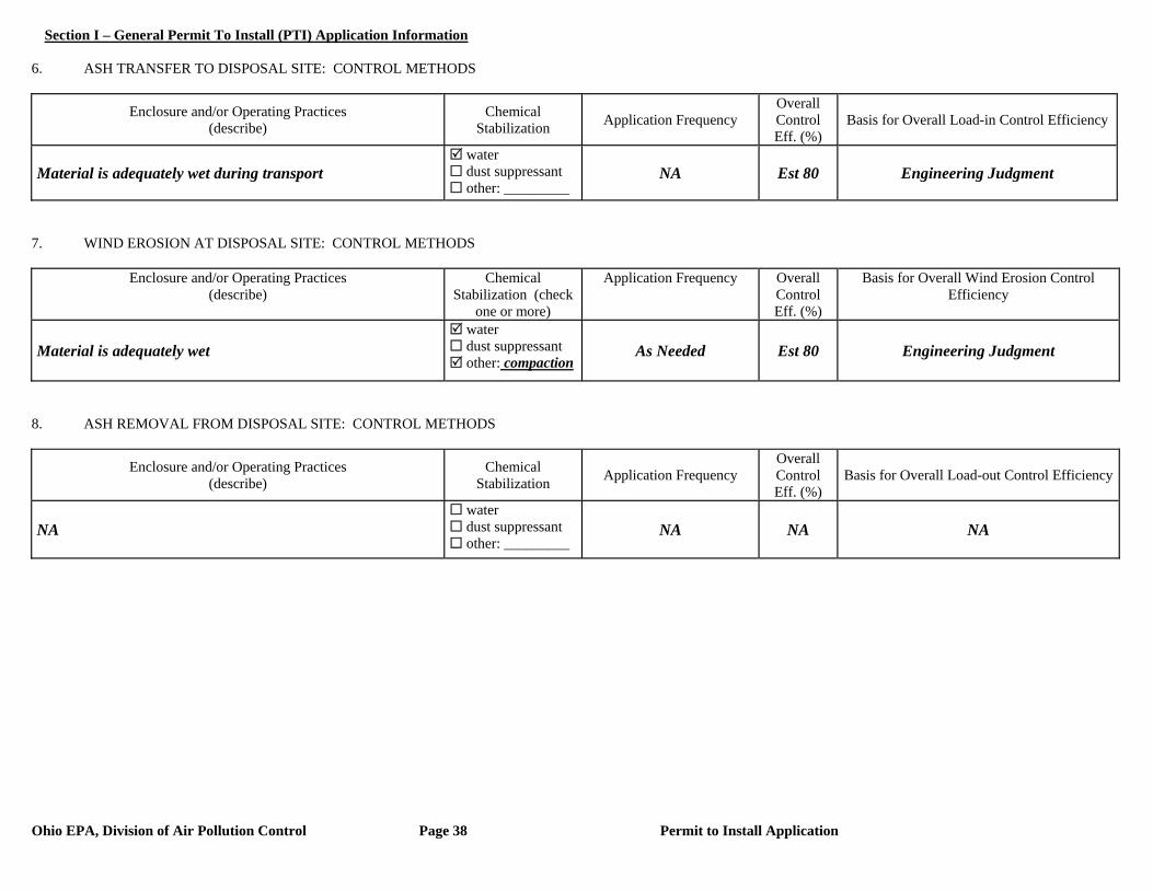
Section I – General Permit To Install (PTI) Application Information
Ohio EPA, Division of Air Pollution Control Page 38 Permit to Install Application
6. ASH TRANSFER TO DISPOSAL SITE: CONTROL METHODS
Enclosure and/or Operating Practices (describe)
Chemical Stabilization Application Frequency
Overall Control Eff. (%)
Basis for Overall Load-in Control Efficiency
Material is adequately wet during transport water dust suppressant other: _________
NA Est 80 Engineering Judgment
7. WIND EROSION AT DISPOSAL SITE: CONTROL METHODS
Enclosure and/or Operating Practices (describe)
Chemical Stabilization (check
one or more)
Application Frequency Overall Control Eff. (%)
Basis for Overall Wind Erosion Control Efficiency
Material is adequately wet water dust suppressant other: compaction
As Needed Est 80 Engineering Judgment
8. ASH REMOVAL FROM DISPOSAL SITE: CONTROL METHODS
Enclosure and/or Operating Practices (describe)
Chemical Stabilization Application Frequency
Overall Control Eff. (%)
Basis for Overall Load-out Control Efficiency
NA water dust suppressant other: _________
NA NA NA

Section II – Specific Air Contaminant Source Information
Ohio EPA, Division of Air Pollution Control Page 39 Permit to Install Application
1. Company identification (name for air contaminant source for which you are applying):
F002 – Paved Roadways 2. List all equipment that are part of this air contaminant source: Vehicle traffic on paved roadways 3. Air Contaminant Source Installation or Modification Schedule (must be completed regardless of date of installation or modification): When did/will you begin to install or modify the air contaminant source? (month/year) 2009 When did/will you begin to operate the air contaminant source? (month/year) 2012 OR after issuance of PTI 4. Emissions Information: The following table requests information needed to determine the applicable requirements and the compliance status of this air contaminant source with those requirements. Suggestions for how to estimate emissions may be found in the instructions to the Emissions Activity Category (EAC) forms required with this application. If you need further assistance, contact your Ohio EPA permit representative.
If total potential emissions of HAPs or any Air Toxic is greater than 1 ton/yr, fill in the table for that (those) pollutant(s).
For all other pollutants, if ‘Emissions before controls (max), lb/hr’ multiplied by 24 hours/day is greater than 10 lb/day, fill in the table for that pollutant.
If you have no add-on control equipment, ‘Emissions before controls’ will be the same as ‘Actual emissions’. Annual emissions should be based on operating 8760 hr/yr unless you are requesting operating restrictions to limit
emissions in line #8 or have described inherent limitations below. If you use units other than lb/hr or ton/yr, specify the units used (e.g., gr/dscf, lb/ton charged, lb/MMBtu, ton/12-months). Requested Allowable (ton/yr) is often equivalent to Potential to Emit (PTE) as defined in OAC rule 3745-31-01(HHH) and
OAC rule 3745-77-01(BB).
Pollutant Emissions
Before Controls (max) (lb/hr)
Actual Emissions
(lb/hr)
Actual Emissions (ton/year)
Requested Allowable
(lb/hr)
Requested Allowable (ton/year)
Paved Roadway PE NA NA #15.10 NA 15.10
Paved Roadway PM10 NA NA #2.94 NA 2.94
Provide your calculations as an attachment and explain how all process variables and emission factors were selected. Note the emissions factor(s) employed and document the origin. Example: AP-42, Table 4.4-3 (8/97); stack test, Method 5, 4/96; mass balance based on MSDS; etc. Refer to the Emission Calculations section of this permit application.
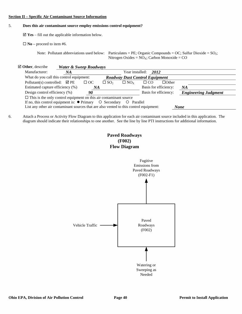
Section II – Specific Air Contaminant Source Information
Ohio EPA, Division of Air Pollution Control Page 40 Permit to Install Application
5. Does this air contaminant source employ emissions control equipment? Yes – fill out the applicable information below. No – proceed to item #6. Note: Pollutant abbreviations used below: Particulates = PE; Organic Compounds = OC; Sulfur Dioxide = SO2; Nitrogen Oxides = NOX; Carbon Monoxide = CO
Other, describe Water & Sweep Roadways Manufacturer: NA Year installed: 2012 What do you call this control equipment: Roadway Dust Control Equipment Pollutant(s) controlled: PE OC SO2 NOX CO Other Estimated capture efficiency (%) NA Basis for efficiency: NA Design control efficiency (%) 90 Basis for efficiency: Engineering Judgment This is the only control equipment on this air contaminant source If no, this control equipment is: Primary Secondary Parallel List any other air contaminant sources that are also vented to this control equipment: None
6. Attach a Process or Activity Flow Diagram to this application for each air contaminant source included in this application. The
diagram should indicate their relationships to one another. See the line by line PTI instructions for additional information.
PavedRoadways
(F002)
FugitiveEmissions from
Paved Roadways(F002-F1)
Vehicle Traffic
Paved Roadways(F002)
Flow Diagram
Watering or Sweeping as
Needed
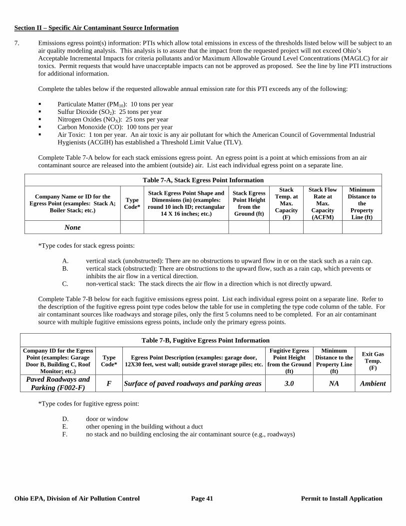
Section II – Specific Air Contaminant Source Information
Ohio EPA, Division of Air Pollution Control Page 41 Permit to Install Application
7. Emissions egress point(s) information: PTIs which allow total emissions in excess of the thresholds listed below will be subject to an
air quality modeling analysis. This analysis is to assure that the impact from the requested project will not exceed Ohio’s Acceptable Incremental Impacts for criteria pollutants and/or Maximum Allowable Ground Level Concentrations (MAGLC) for air toxics. Permit requests that would have unacceptable impacts can not be approved as proposed. See the line by line PTI instructions for additional information.
Complete the tables below if the requested allowable annual emission rate for this PTI exceeds any of the following:
Particulate Matter (PM10): 10 tons per year Sulfur Dioxide (SO2): 25 tons per year Nitrogen Oxides (NOX): 25 tons per year Carbon Monoxide (CO): 100 tons per year Air Toxic: 1 ton per year. An air toxic is any air pollutant for which the American Council of Governmental Industrial
Hygienists (ACGIH) has established a Threshold Limit Value (TLV).
Complete Table 7-A below for each stack emissions egress point. An egress point is a point at which emissions from an air contaminant source are released into the ambient (outside) air. List each individual egress point on a separate line.
*Type codes for stack egress points:
A. vertical stack (unobstructed): There are no obstructions to upward flow in or on the stack such as a rain cap. B. vertical stack (obstructed): There are obstructions to the upward flow, such as a rain cap, which prevents or
inhibits the air flow in a vertical direction. C. non-vertical stack: The stack directs the air flow in a direction which is not directly upward.
Complete Table 7-B below for each fugitive emissions egress point. List each individual egress point on a separate line. Refer to the description of the fugitive egress point type codes below the table for use in completing the type code column of the table. For air contaminant sources like roadways and storage piles, only the first 5 columns need to be completed. For an air contaminant source with multiple fugitive emissions egress points, include only the primary egress points.
Table 7-B, Fugitive Egress Point Information
Company ID for the Egress Point (examples: Garage Door B, Building C, Roof
Monitor; etc.)
Type Code*
Egress Point Description (examples: garage door, 12X30 feet, west wall; outside gravel storage piles; etc.
Fugitive Egress Point Height
from the Ground (ft)
Minimum Distance to the Property Line
(ft)
Exit Gas Temp.
(F)
Paved Roadways and Parking (F002-F) F Surface of paved roadways and parking areas 3.0 NA Ambient
*Type codes for fugitive egress point:
D. door or window E. other opening in the building without a duct F. no stack and no building enclosing the air contaminant source (e.g., roadways)
Table 7-A, Stack Egress Point Information
Company Name or ID for the Egress Point (examples: Stack A;
Boiler Stack; etc.)
Type Code*
Stack Egress Point Shape and Dimensions (in) (examples:
round 10 inch ID; rectangular 14 X 16 inches; etc.)
Stack Egress Point Height
from the Ground (ft)
Stack Temp. at
Max. Capacity
(F)
Stack Flow Rate at Max.
Capacity (ACFM)
Minimum Distance to
the Property Line (ft)
None
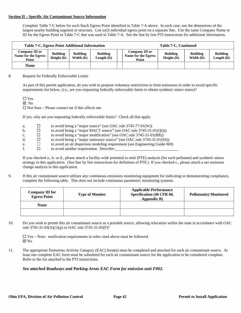
Section II – Specific Air Contaminant Source Information
Ohio EPA, Division of Air Pollution Control Page 42 Permit to Install Application
Complete Table 7-C below for each Stack Egress Point identified in Table 7-A above. In each case, use the dimensions of the largest nearby building segment or structure. List each individual egress point on a separate line. Use the same Company Name or ID for the Egress Point in Table 7-C that was used in Table 7-A. See the line by line PTI instructions for additional information.
Table 7-C, Egress Point Additional Information Table 7-C, Continued
Company ID or Name for the Egress
Point
Building Height (ft)
Building Width (ft)
Building Length (ft)
Company ID or Name for the Egress
Point
Building Height (ft)
Building Width (ft)
Building Length (ft)
None 8. Request for Federally Enforceable Limits
As part of this permit application, do you wish to propose voluntary restrictions to limit emissions in order to avoid specific requirements list below, (i.e., are you requesting federally enforceable limits to obtain synthetic minor status)?
Yes No Not Sure – Please contact me if this affects me.
If yes, why are you requesting federally enforceable limits? Check all that apply. a. to avoid being a “major source” (see OAC rule 3745-77-01(W)) b. to avoid being a “major MACT source” (see OAC rule 3745-31-01(QQ)) c. to avoid being a “major modification” (see OAC rule 3745-31-01(RR)) d. to avoid being a “major stationary source” (see OAC rule 3745-31-01(SS)) e. to avoid an air dispersion modeling requirement (see Engineering Guide #69) f. to avoid another requirement. Describe: If you checked a., b. or d., please attach a facility-wide potential to emit (PTE) analysis (for each pollutant) and synthetic minor strategy to this application. (See line by line instructions for definition of PTE.) If you checked c., please attach a net emission change analysis to this application.
9. If this air contaminant source utilizes any continuous emissions monitoring equipment for indicating or demonstrating compliance, complete the following table. This does not include continuous parametric monitoring systems.
Company ID for Egress Point Type of Monitor
Applicable Performance Specification (40 CFR 60,
Appendix B) Pollutant(s) Monitored
None
10. Do you wish to permit this air contaminant source as a portable source, allowing relocation within the state in accordance with OAC
rule 3745-31-03(A)(1)(p) or OAC rule 3745-31-05(F)?
Yes – Note: notification requirements in rules cited above must be followed. No
11. The appropriate Emissions Activity Category (EAC) form(s) must be completed and attached for each air contaminant source. At
least one complete EAC form must be submitted for each air contaminant source for the application to be considered complete. Refer to the list attached to the PTI instructions. See attached Roadways and Parking Areas EAC Form for emission unit F002.
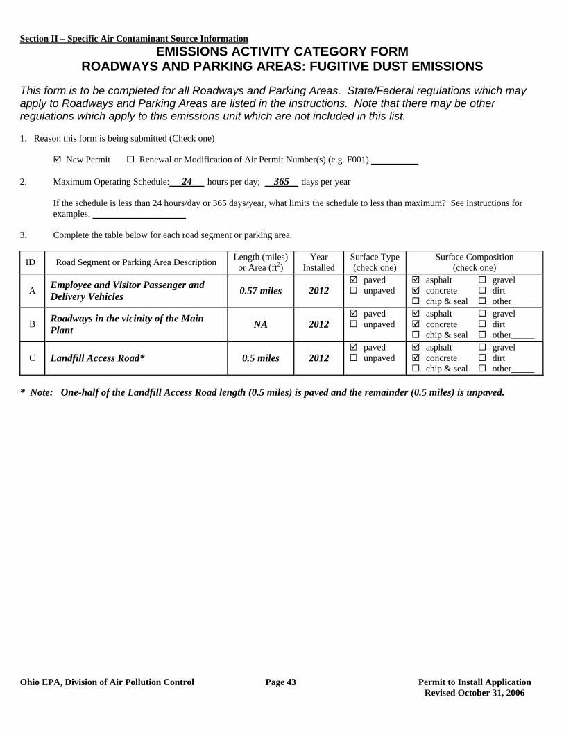
Section II – Specific Air Contaminant Source Information
Ohio EPA, Division of Air Pollution Control Page 43 Permit to Install Application Revised October 31, 2006
EMISSIONS ACTIVITY CATEGORY FORM ROADWAYS AND PARKING AREAS: FUGITIVE DUST EMISSIONS
This form is to be completed for all Roadways and Parking Areas. State/Federal regulations which may apply to Roadways and Parking Areas are listed in the instructions. Note that there may be other regulations which apply to this emissions unit which are not included in this list. 1. Reason this form is being submitted (Check one)
New Permit Renewal or Modification of Air Permit Number(s) (e.g. F001)
2. Maximum Operating Schedule: 24 hours per day; 365 days per year
If the schedule is less than 24 hours/day or 365 days/year, what limits the schedule to less than maximum? See instructions for examples.
3. Complete the table below for each road segment or parking area.
ID Road Segment or Parking Area Description Length (miles) or Area (ft2)
Year Installed
Surface Type (check one)
Surface Composition (check one)
A Employee and Visitor Passenger and Delivery Vehicles 0.57 miles 2012
paved unpaved
asphalt gravel concrete dirt chip & seal other_____
B Roadways in the vicinity of the Main Plant NA 2012
paved unpaved
asphalt gravel concrete dirt chip & seal other_____
C Landfill Access Road* 0.5 miles 2012 paved unpaved
asphalt gravel concrete dirt chip & seal other_____
* Note: One-half of the Landfill Access Road length (0.5 miles) is paved and the remainder (0.5 miles) is unpaved.
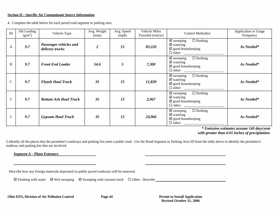
Section II – Specific Air Contaminant Source Information
Ohio EPA, Division of Air Pollution Control Page 44 Permit to Install Application Revised October 31, 2006
4. Complete the table below for each paved road segment or parking area.
ID Silt Loading (g/m2) Vehicle Type Avg. Weight
(tons) Avg. Speed
(mph) Vehicle Miles
Traveled (vmt/yr) Control Method(s) Application or Usage Frequency
A 9.7 Passenger vehicles and delivery trucks 2 15 83,220
sweeping flushing watering good housekeeping other: _______________________
As Needed*
B 9.7 Front End Loader 54.6 5 7,300 sweeping flushing watering good housekeeping other: _______________________
As Needed*
C 9.7 Flyash Haul Truck 35 15 11,839 sweeping flushing watering good housekeeping other: _______________________
As Needed*
C 9.7 Bottom Ash Haul Truck 35 15 2,967 sweeping flushing watering good housekeeping other: _______________________
As Needed*
C 9.7 Gypsum Haul Truck 35 15 24,966 sweeping flushing watering good housekeeping other: _______________________
As Needed*
* Emission estimates assume 140 days/year with greater than 0.01 inches of precipitation.
5. Identify all the places that the permittee=s roadways and parking lots meet a public road. Use the Road Segment or Parking Area ID from the table above to identify the permittee=s roadway and parking lots that are involved. Segment A - Plant Entrance
Describe how any foreign materials deposited on public paved roadways will be removed.
Flushing with water Wet sweeping Sweeping with vacuum truck Other. Describe
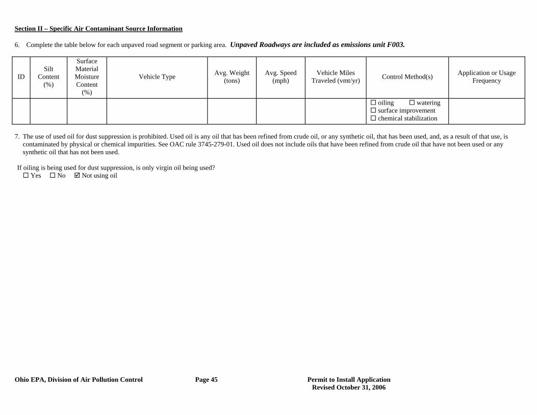
Section II – Specific Air Contaminant Source Information
Ohio EPA, Division of Air Pollution Control Page 45 Permit to Install Application Revised October 31, 2006
6. Complete the table below for each unpaved road segment or parking area. Unpaved Roadways are included as emissions unit F003.
ID Silt
Content (%)
Surface Material Moisture Content
(%)
Vehicle Type Avg. Weight (tons)
Avg. Speed (mph)
Vehicle Miles Traveled (vmt/yr) Control Method(s) Application or Usage
Frequency
oiling watering surface improvement chemical stabilization
7. The use of used oil for dust suppression is prohibited. Used oil is any oil that has been refined from crude oil, or any synthetic oil, that has been used, and, as a result of that use, is
contaminated by physical or chemical impurities. See OAC rule 3745-279-01. Used oil does not include oils that have been refined from crude oil that have not been used or any synthetic oil that has not been used.
If oiling is being used for dust suppression, is only virgin oil being used?
Yes No Not using oil
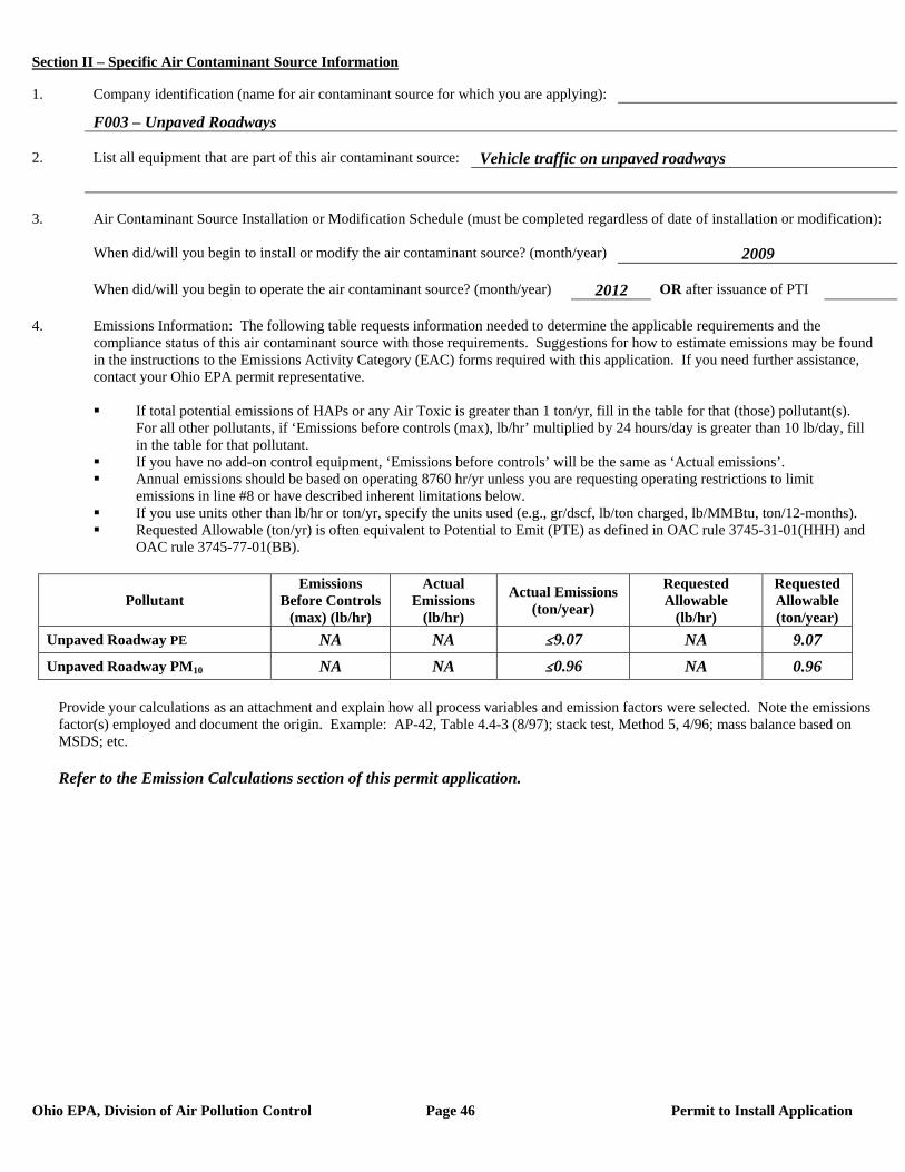
Section II – Specific Air Contaminant Source Information
Ohio EPA, Division of Air Pollution Control Page 46 Permit to Install Application
1. Company identification (name for air contaminant source for which you are applying):
F003 – Unpaved Roadways 2. List all equipment that are part of this air contaminant source: Vehicle traffic on unpaved roadways 3. Air Contaminant Source Installation or Modification Schedule (must be completed regardless of date of installation or modification): When did/will you begin to install or modify the air contaminant source? (month/year) 2009 When did/will you begin to operate the air contaminant source? (month/year) 2012 OR after issuance of PTI 4. Emissions Information: The following table requests information needed to determine the applicable requirements and the compliance status of this air contaminant source with those requirements. Suggestions for how to estimate emissions may be found in the instructions to the Emissions Activity Category (EAC) forms required with this application. If you need further assistance, contact your Ohio EPA permit representative.
If total potential emissions of HAPs or any Air Toxic is greater than 1 ton/yr, fill in the table for that (those) pollutant(s).
For all other pollutants, if ‘Emissions before controls (max), lb/hr’ multiplied by 24 hours/day is greater than 10 lb/day, fill in the table for that pollutant.
If you have no add-on control equipment, ‘Emissions before controls’ will be the same as ‘Actual emissions’. Annual emissions should be based on operating 8760 hr/yr unless you are requesting operating restrictions to limit
emissions in line #8 or have described inherent limitations below. If you use units other than lb/hr or ton/yr, specify the units used (e.g., gr/dscf, lb/ton charged, lb/MMBtu, ton/12-months). Requested Allowable (ton/yr) is often equivalent to Potential to Emit (PTE) as defined in OAC rule 3745-31-01(HHH) and
OAC rule 3745-77-01(BB).
Pollutant Emissions
Before Controls (max) (lb/hr)
Actual Emissions
(lb/hr)
Actual Emissions (ton/year)
Requested Allowable
(lb/hr)
Requested Allowable (ton/year)
Unpaved Roadway PE NA NA #9.07 NA 9.07 Unpaved Roadway PM10 NA NA #0.96 NA 0.96
Provide your calculations as an attachment and explain how all process variables and emission factors were selected. Note the emissions factor(s) employed and document the origin. Example: AP-42, Table 4.4-3 (8/97); stack test, Method 5, 4/96; mass balance based on MSDS; etc. Refer to the Emission Calculations section of this permit application.
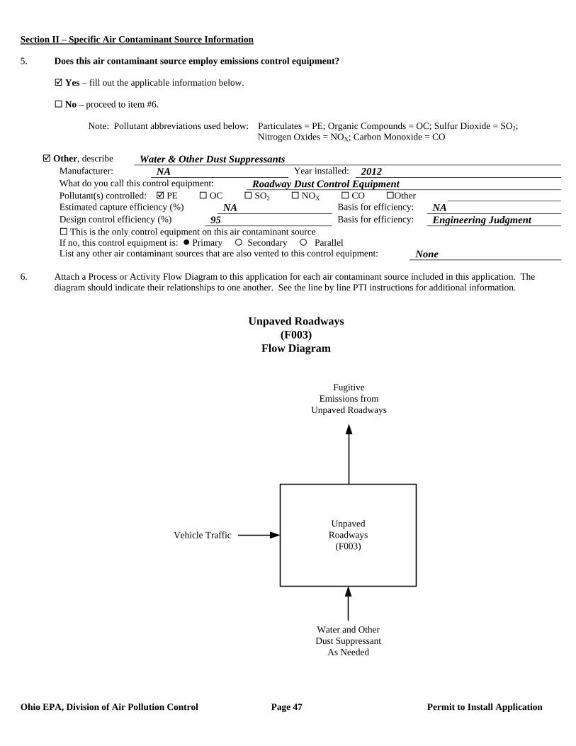
Section II – Specific Air Contaminant Source Information
Ohio EPA, Division of Air Pollution Control Page 47 Permit to Install Application
5. Does this air contaminant source employ emissions control equipment? Yes – fill out the applicable information below. No – proceed to item #6. Note: Pollutant abbreviations used below: Particulates = PE; Organic Compounds = OC; Sulfur Dioxide = SO2; Nitrogen Oxides = NOX; Carbon Monoxide = CO
Other, describe Water & Other Dust Suppressants Manufacturer: NA Year installed: 2012 What do you call this control equipment: Roadway Dust Control Equipment Pollutant(s) controlled: PE OC SO2 NOX CO Other Estimated capture efficiency (%) NA Basis for efficiency: NA Design control efficiency (%) 95 Basis for efficiency: Engineering Judgment This is the only control equipment on this air contaminant source If no, this control equipment is: Primary Secondary Parallel List any other air contaminant sources that are also vented to this control equipment: None
6. Attach a Process or Activity Flow Diagram to this application for each air contaminant source included in this application. The
diagram should indicate their relationships to one another. See the line by line PTI instructions for additional information.
UnpavedRoadways
(F003)Vehicle Traffic
Unpaved Roadways(F003)
Flow Diagram
FugitiveEmissions from
Unpaved Roadways
Water and Other Dust Suppressant
As Needed

Section II – Specific Air Contaminant Source Information
Ohio EPA, Division of Air Pollution Control Page 48 Permit to Install Application
7. Emissions egress point(s) information: PTIs which allow total emissions in excess of the thresholds listed below will be subject to an
air quality modeling analysis. This analysis is to assure that the impact from the requested project will not exceed Ohio’s Acceptable Incremental Impacts for criteria pollutants and/or Maximum Allowable Ground Level Concentrations (MAGLC) for air toxics. Permit requests that would have unacceptable impacts can not be approved as proposed. See the line by line PTI instructions for additional information.
Complete the tables below if the requested allowable annual emission rate for this PTI exceeds any of the following:
Particulate Matter (PM10): 10 tons per year Sulfur Dioxide (SO2): 25 tons per year Nitrogen Oxides (NOX): 25 tons per year Carbon Monoxide (CO): 100 tons per year Air Toxic: 1 ton per year. An air toxic is any air pollutant for which the American Council of Governmental Industrial
Hygienists (ACGIH) has established a Threshold Limit Value (TLV).
Complete Table 7-A below for each stack emissions egress point. An egress point is a point at which emissions from an air contaminant source are released into the ambient (outside) air. List each individual egress point on a separate line.
(1) Note: The total annual PM10 emissions from the Unpaved Roadways (F003) are less than 1.0 ton. As a result, this emissions unit was not included in the air quality modeling submitted with this PTI application.
*Type codes for stack egress points:
A. vertical stack (unobstructed): There are no obstructions to upward flow in or on the stack such as a rain cap. B. vertical stack (obstructed): There are obstructions to the upward flow, such as a rain cap, which prevents or
inhibits the air flow in a vertical direction. C. non-vertical stack: The stack directs the air flow in a direction which is not directly upward.
Complete Table 7-B below for each fugitive emissions egress point. List each individual egress point on a separate line. Refer to the description of the fugitive egress point type codes below the table for use in completing the type code column of the table. For air contaminant sources like roadways and storage piles, only the first 5 columns need to be completed. For an air contaminant source with multiple fugitive emissions egress points, include only the primary egress points.
Table 7-B, Fugitive Egress Point Information
Company ID for the Egress Point (examples: Garage Door B, Building C, Roof
Monitor; etc.)
Type Code*
Egress Point Description (examples: garage door, 12X30 feet, west wall; outside gravel storage piles; etc.
Fugitive Egress Point Height
from the Ground (ft)
Minimum Distance to the Property Line
(ft)
Exit Gas Temp.
(F)
NA NA NA NA NA NA
*Type codes for fugitive egress point:
D. door or window E. other opening in the building without a duct F. no stack and no building enclosing the air contaminant source (e.g., roadways)
Table 7-A, Stack Egress Point Information
Company Name or ID for the Egress Point (examples: Stack A;
Boiler Stack; etc.)
Type Code*
Stack Egress Point Shape and Dimensions (in) (examples:
round 10 inch ID; rectangular 14 X 16 inches; etc.)
Stack Egress Point Height
from the Ground (ft)
Stack Temp. at
Max. Capacity
(F)
Stack Flow Rate at Max.
Capacity (ACFM)
Minimum Distance to
the Property Line (ft)
NA(1) NA NA NA NA NA NA
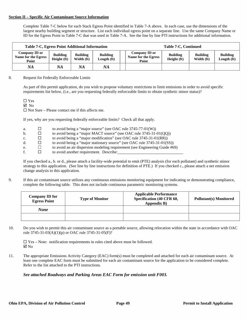
Section II – Specific Air Contaminant Source Information
Ohio EPA, Division of Air Pollution Control Page 49 Permit to Install Application
Complete Table 7-C below for each Stack Egress Point identified in Table 7-A above. In each case, use the dimensions of the largest nearby building segment or structure. List each individual egress point on a separate line. Use the same Company Name or ID for the Egress Point in Table 7-C that was used in Table 7-A. See the line by line PTI instructions for additional information.
Table 7-C, Egress Point Additional Information Table 7-C, Continued
Company ID or Name for the Egress
Point
Building Height (ft)
Building Width (ft)
Building Length (ft)
Company ID or Name for the Egress
Point
Building Height (ft)
Building Width (ft)
Building Length (ft)
NA NA NA NA 8. Request for Federally Enforceable Limits
As part of this permit application, do you wish to propose voluntary restrictions to limit emissions in order to avoid specific requirements list below, (i.e., are you requesting federally enforceable limits to obtain synthetic minor status)?
Yes No Not Sure – Please contact me if this affects me.
If yes, why are you requesting federally enforceable limits? Check all that apply. a. to avoid being a “major source” (see OAC rule 3745-77-01(W)) b. to avoid being a “major MACT source” (see OAC rule 3745-31-01(QQ)) c. to avoid being a “major modification” (see OAC rule 3745-31-01(RR)) d. to avoid being a “major stationary source” (see OAC rule 3745-31-01(SS)) e. to avoid an air dispersion modeling requirement (see Engineering Guide #69) f. to avoid another requirement. Describe: If you checked a., b. or d., please attach a facility-wide potential to emit (PTE) analysis (for each pollutant) and synthetic minor strategy to this application. (See line by line instructions for definition of PTE.) If you checked c., please attach a net emission change analysis to this application.
9. If this air contaminant source utilizes any continuous emissions monitoring equipment for indicating or demonstrating compliance, complete the following table. This does not include continuous parametric monitoring systems.
Company ID for Egress Point Type of Monitor
Applicable Performance Specification (40 CFR 60,
Appendix B) Pollutant(s) Monitored
None
10. Do you wish to permit this air contaminant source as a portable source, allowing relocation within the state in accordance with OAC
rule 3745-31-03(A)(1)(p) or OAC rule 3745-31-05(F)?
Yes – Note: notification requirements in rules cited above must be followed. No
11. The appropriate Emissions Activity Category (EAC) form(s) must be completed and attached for each air contaminant source. At
least one complete EAC form must be submitted for each air contaminant source for the application to be considered complete. Refer to the list attached to the PTI instructions. See attached Roadways and Parking Areas EAC Form for emission unit F003.
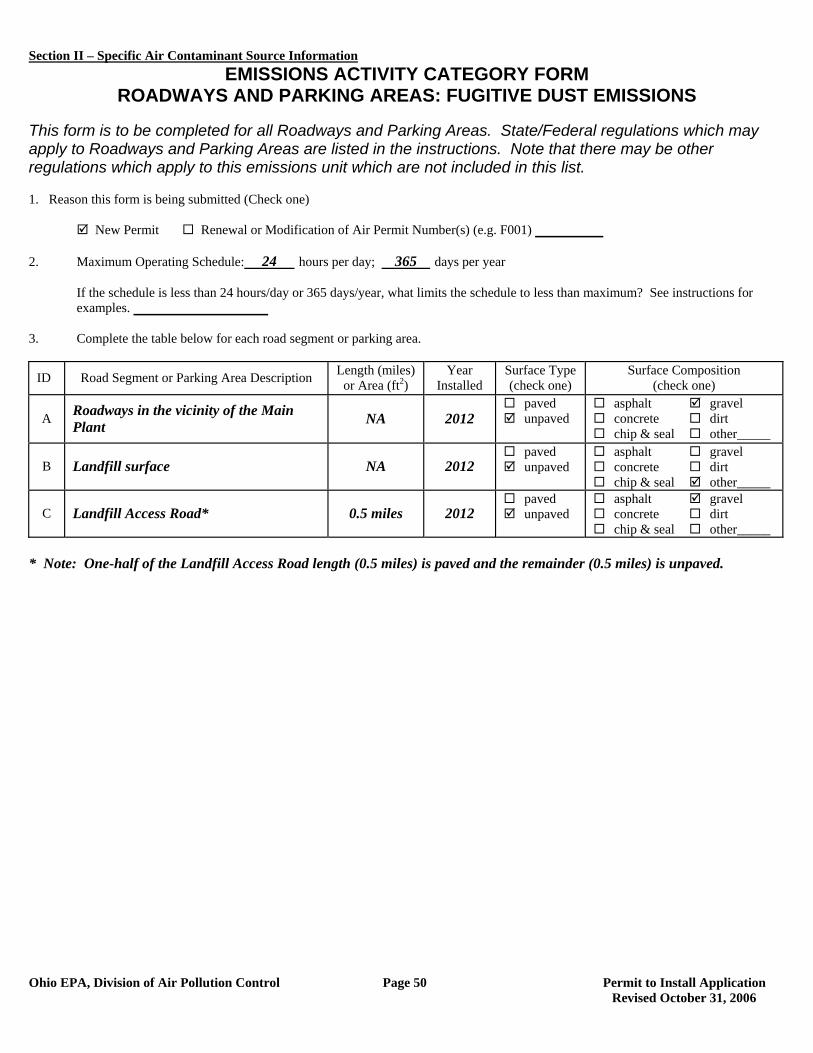
Section II – Specific Air Contaminant Source Information
Ohio EPA, Division of Air Pollution Control Page 50 Permit to Install Application Revised October 31, 2006
EMISSIONS ACTIVITY CATEGORY FORM ROADWAYS AND PARKING AREAS: FUGITIVE DUST EMISSIONS
This form is to be completed for all Roadways and Parking Areas. State/Federal regulations which may apply to Roadways and Parking Areas are listed in the instructions. Note that there may be other regulations which apply to this emissions unit which are not included in this list. 1. Reason this form is being submitted (Check one)
New Permit Renewal or Modification of Air Permit Number(s) (e.g. F001)
2. Maximum Operating Schedule: 24 hours per day; 365 days per year
If the schedule is less than 24 hours/day or 365 days/year, what limits the schedule to less than maximum? See instructions for examples.
3. Complete the table below for each road segment or parking area.
ID Road Segment or Parking Area Description Length (miles) or Area (ft2)
Year Installed
Surface Type (check one)
Surface Composition (check one)
A Roadways in the vicinity of the Main Plant NA 2012
paved unpaved
asphalt gravel concrete dirt chip & seal other_____
B Landfill surface NA 2012 paved unpaved
asphalt gravel concrete dirt chip & seal other_____
C Landfill Access Road* 0.5 miles 2012 paved unpaved
asphalt gravel concrete dirt chip & seal other_____
* Note: One-half of the Landfill Access Road length (0.5 miles) is paved and the remainder (0.5 miles) is unpaved.
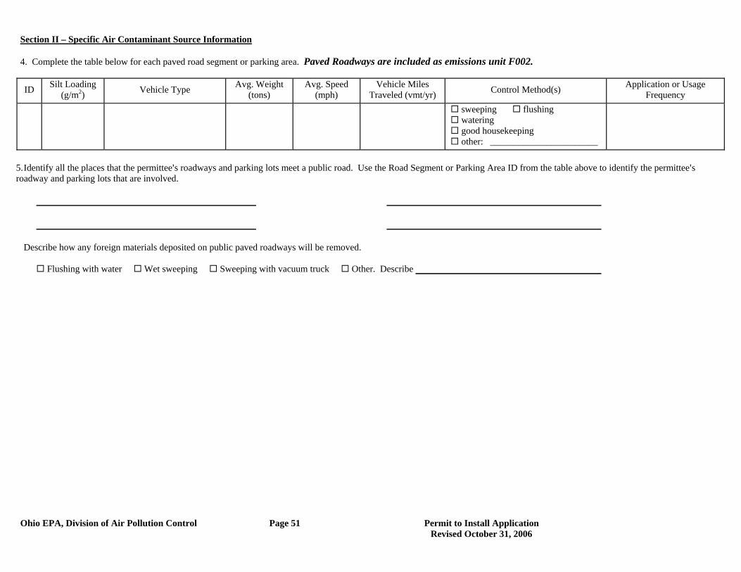
Section II – Specific Air Contaminant Source Information
Ohio EPA, Division of Air Pollution Control Page 51 Permit to Install Application Revised October 31, 2006
4. Complete the table below for each paved road segment or parking area. Paved Roadways are included as emissions unit F002.
ID Silt Loading (g/m2) Vehicle Type Avg. Weight
(tons) Avg. Speed
(mph) Vehicle Miles
Traveled (vmt/yr) Control Method(s) Application or Usage Frequency
sweeping flushing watering good housekeeping other: _______________________
5. Identify all the places that the permittee=s roadways and parking lots meet a public road. Use the Road Segment or Parking Area ID from the table above to identify the permittee=s roadway and parking lots that are involved.
Describe how any foreign materials deposited on public paved roadways will be removed.
Flushing with water Wet sweeping Sweeping with vacuum truck Other. Describe
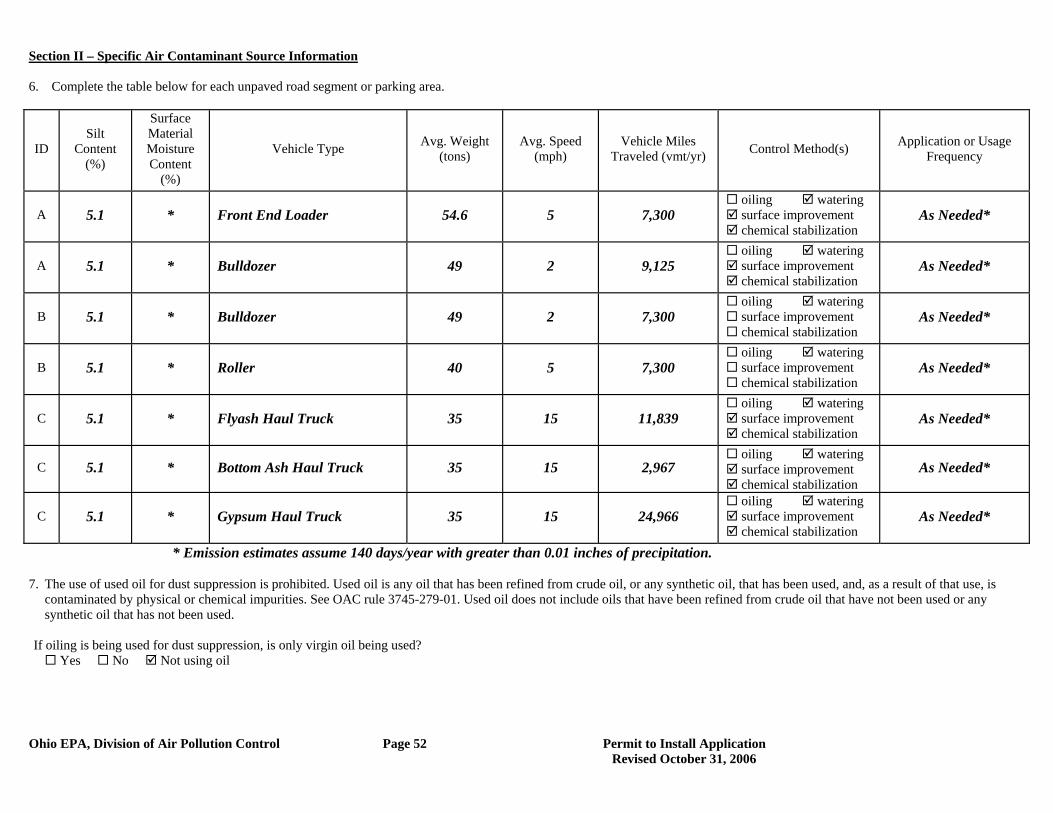
Section II – Specific Air Contaminant Source Information
Ohio EPA, Division of Air Pollution Control Page 52 Permit to Install Application Revised October 31, 2006
6. Complete the table below for each unpaved road segment or parking area.
ID Silt
Content (%)
Surface Material Moisture Content
(%)
Vehicle Type Avg. Weight (tons)
Avg. Speed (mph)
Vehicle Miles Traveled (vmt/yr) Control Method(s) Application or Usage
Frequency
A 5.1 * Front End Loader 54.6 5 7,300 oiling watering surface improvement chemical stabilization
As Needed*
A 5.1 * Bulldozer 49 2 9,125 oiling watering surface improvement chemical stabilization
As Needed*
B 5.1 * Bulldozer 49 2 7,300 oiling watering surface improvement chemical stabilization
As Needed*
B 5.1 * Roller 40 5 7,300 oiling watering surface improvement chemical stabilization
As Needed*
C 5.1 * Flyash Haul Truck 35 15 11,839 oiling watering surface improvement chemical stabilization
As Needed*
C 5.1 * Bottom Ash Haul Truck 35 15 2,967 oiling watering surface improvement chemical stabilization
As Needed*
C 5.1 * Gypsum Haul Truck 35 15 24,966 oiling watering surface improvement chemical stabilization
As Needed*
* Emission estimates assume 140 days/year with greater than 0.01 inches of precipitation. 7. The use of used oil for dust suppression is prohibited. Used oil is any oil that has been refined from crude oil, or any synthetic oil, that has been used, and, as a result of that use, is
contaminated by physical or chemical impurities. See OAC rule 3745-279-01. Used oil does not include oils that have been refined from crude oil that have not been used or any synthetic oil that has not been used.
If oiling is being used for dust suppression, is only virgin oil being used?
Yes No Not using oil
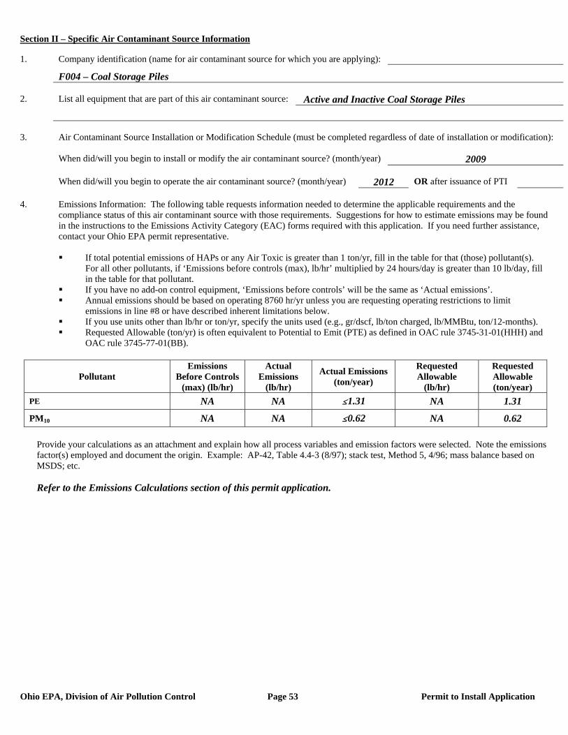
Section II – Specific Air Contaminant Source Information
Ohio EPA, Division of Air Pollution Control Page 53 Permit to Install Application
1. Company identification (name for air contaminant source for which you are applying):
F004 – Coal Storage Piles 2. List all equipment that are part of this air contaminant source: Active and Inactive Coal Storage Piles 3. Air Contaminant Source Installation or Modification Schedule (must be completed regardless of date of installation or modification): When did/will you begin to install or modify the air contaminant source? (month/year) 2009 When did/will you begin to operate the air contaminant source? (month/year) 2012 OR after issuance of PTI 4. Emissions Information: The following table requests information needed to determine the applicable requirements and the compliance status of this air contaminant source with those requirements. Suggestions for how to estimate emissions may be found in the instructions to the Emissions Activity Category (EAC) forms required with this application. If you need further assistance, contact your Ohio EPA permit representative.
If total potential emissions of HAPs or any Air Toxic is greater than 1 ton/yr, fill in the table for that (those) pollutant(s).
For all other pollutants, if ‘Emissions before controls (max), lb/hr’ multiplied by 24 hours/day is greater than 10 lb/day, fill in the table for that pollutant.
If you have no add-on control equipment, ‘Emissions before controls’ will be the same as ‘Actual emissions’. Annual emissions should be based on operating 8760 hr/yr unless you are requesting operating restrictions to limit
emissions in line #8 or have described inherent limitations below. If you use units other than lb/hr or ton/yr, specify the units used (e.g., gr/dscf, lb/ton charged, lb/MMBtu, ton/12-months). Requested Allowable (ton/yr) is often equivalent to Potential to Emit (PTE) as defined in OAC rule 3745-31-01(HHH) and
OAC rule 3745-77-01(BB).
Pollutant Emissions
Before Controls (max) (lb/hr)
Actual Emissions
(lb/hr)
Actual Emissions (ton/year)
Requested Allowable
(lb/hr)
Requested Allowable (ton/year)
PE NA NA #1.31 NA 1.31
PM10 NA NA #0.62 NA 0.62
Provide your calculations as an attachment and explain how all process variables and emission factors were selected. Note the emissions factor(s) employed and document the origin. Example: AP-42, Table 4.4-3 (8/97); stack test, Method 5, 4/96; mass balance based on MSDS; etc. Refer to the Emissions Calculations section of this permit application.
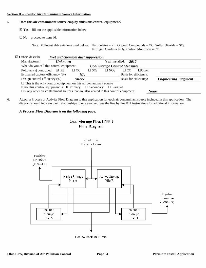
Section II – Specific Air Contaminant Source Information
Ohio EPA, Division of Air Pollution Control Page 54 Permit to Install Application
5. Does this air contaminant source employ emissions control equipment? Yes – fill out the applicable information below. No – proceed to item #6. Note: Pollutant abbreviations used below: Particulates = PE; Organic Compounds = OC; Sulfur Dioxide = SO2; Nitrogen Oxides = NOX; Carbon Monoxide = CO
Other, describe Wet and chemical dust suppression Manufacturer: Unknown Year installed: 2012 What do you call this control equipment: Coal Storage Control Measures Pollutant(s) controlled: PE OC SO2 NOX CO Other Estimated capture efficiency (%) NA Basis for efficiency: Design control efficiency (%) 90-95 Basis for efficiency: Engineering Judgment This is the only control equipment on this air contaminant source If no, this control equipment is: Primary Secondary Parallel List any other air contaminant sources that are also vented to this control equipment: None
6. Attach a Process or Activity Flow Diagram to this application for each air contaminant source included in this application. The
diagram should indicate their relationships to one another. See the line by line PTI instructions for additional information. A Process Flow Diagram is on the following page.
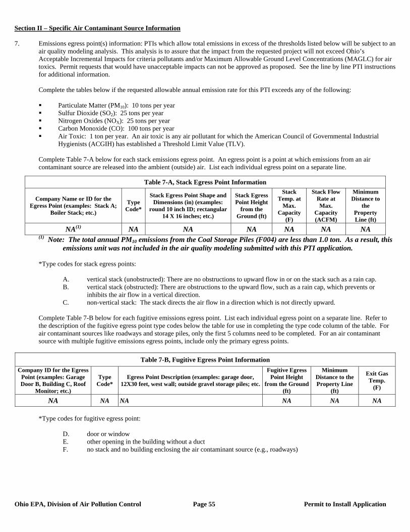
Section II – Specific Air Contaminant Source Information
Ohio EPA, Division of Air Pollution Control Page 55 Permit to Install Application
7. Emissions egress point(s) information: PTIs which allow total emissions in excess of the thresholds listed below will be subject to an
air quality modeling analysis. This analysis is to assure that the impact from the requested project will not exceed Ohio’s Acceptable Incremental Impacts for criteria pollutants and/or Maximum Allowable Ground Level Concentrations (MAGLC) for air toxics. Permit requests that would have unacceptable impacts can not be approved as proposed. See the line by line PTI instructions for additional information.
Complete the tables below if the requested allowable annual emission rate for this PTI exceeds any of the following:
Particulate Matter (PM10): 10 tons per year Sulfur Dioxide (SO2): 25 tons per year Nitrogen Oxides (NOX): 25 tons per year Carbon Monoxide (CO): 100 tons per year Air Toxic: 1 ton per year. An air toxic is any air pollutant for which the American Council of Governmental Industrial
Hygienists (ACGIH) has established a Threshold Limit Value (TLV).
Complete Table 7-A below for each stack emissions egress point. An egress point is a point at which emissions from an air contaminant source are released into the ambient (outside) air. List each individual egress point on a separate line.
(1) Note: The total annual PM10 emissions from the Coal Storage Piles (F004) are less than 1.0 ton. As a result, this emissions unit was not included in the air quality modeling submitted with this PTI application.
*Type codes for stack egress points:
A. vertical stack (unobstructed): There are no obstructions to upward flow in or on the stack such as a rain cap. B. vertical stack (obstructed): There are obstructions to the upward flow, such as a rain cap, which prevents or
inhibits the air flow in a vertical direction. C. non-vertical stack: The stack directs the air flow in a direction which is not directly upward.
Complete Table 7-B below for each fugitive emissions egress point. List each individual egress point on a separate line. Refer to the description of the fugitive egress point type codes below the table for use in completing the type code column of the table. For air contaminant sources like roadways and storage piles, only the first 5 columns need to be completed. For an air contaminant source with multiple fugitive emissions egress points, include only the primary egress points.
Table 7-B, Fugitive Egress Point Information
Company ID for the Egress Point (examples: Garage Door B, Building C, Roof
Monitor; etc.)
Type Code*
Egress Point Description (examples: garage door, 12X30 feet, west wall; outside gravel storage piles; etc.
Fugitive Egress Point Height
from the Ground (ft)
Minimum Distance to the Property Line
(ft)
Exit Gas Temp.
(F)
NA NA NA NA NA NA
*Type codes for fugitive egress point:
D. door or window E. other opening in the building without a duct F. no stack and no building enclosing the air contaminant source (e.g., roadways)
Table 7-A, Stack Egress Point Information
Company Name or ID for the Egress Point (examples: Stack A;
Boiler Stack; etc.)
Type Code*
Stack Egress Point Shape and Dimensions (in) (examples:
round 10 inch ID; rectangular 14 X 16 inches; etc.)
Stack Egress Point Height
from the Ground (ft)
Stack Temp. at
Max. Capacity
(F)
Stack Flow Rate at Max.
Capacity (ACFM)
Minimum Distance to
the Property Line (ft)
NA(1) NA NA NA NA NA NA

Section II – Specific Air Contaminant Source Information
Ohio EPA, Division of Air Pollution Control Page 56 Permit to Install Application
Complete Table 7-C below for each Stack Egress Point identified in Table 7-A above. In each case, use the dimensions of the largest nearby building segment or structure. List each individual egress point on a separate line. Use the same Company Name or ID for the Egress Point in Table 7-C that was used in Table 7-A. See the line by line PTI instructions for additional information.
Table 7-C, Egress Point Additional Information Table 7-C, Continued
Company ID or Name for the Egress
Point
Building Height (ft)
Building Width (ft)
Building Length (ft)
Company ID or Name for the Egress
Point
Building Height (ft)
Building Width (ft)
Building Length (ft)
NA NA NA NA 8. Request for Federally Enforceable Limits
As part of this permit application, do you wish to propose voluntary restrictions to limit emissions in order to avoid specific requirements list below, (i.e., are you requesting federally enforceable limits to obtain synthetic minor status)?
Yes No Not Sure – Please contact me if this affects me.
If yes, why are you requesting federally enforceable limits? Check all that apply. a. to avoid being a “major source” (see OAC rule 3745-77-01(W)) b. to avoid being a “major MACT source” (see OAC rule 3745-31-01(QQ)) c. to avoid being a “major modification” (see OAC rule 3745-31-01(RR)) d. to avoid being a “major stationary source” (see OAC rule 3745-31-01(SS)) e. to avoid an air dispersion modeling requirement (see Engineering Guide #69) f. to avoid another requirement. Describe: If you checked a., b. or d., please attach a facility-wide potential to emit (PTE) analysis (for each pollutant) and synthetic minor strategy to this application. (See line by line instructions for definition of PTE.) If you checked c., please attach a net emission change analysis to this application.
9. If this air contaminant source utilizes any continuous emissions monitoring equipment for indicating or demonstrating compliance, complete the following table. This does not include continuous parametric monitoring systems.
Company ID for Egress Point Type of Monitor
Applicable Performance Specification (40 CFR 60,
Appendix B) Pollutant(s) Monitored
None
10. Do you wish to permit this air contaminant source as a portable source, allowing relocation within the state in accordance with OAC
rule 3745-31-03(A)(1)(p) or OAC rule 3745-31-05(F)?
Yes – Note: notification requirements in rules cited above must be followed. No
11. The appropriate Emissions Activity Category (EAC) form(s) must be completed and attached for each air contaminant source. At
least one complete EAC form must be submitted for each air contaminant source for the application to be considered complete. Refer to the list attached to the PTI instructions. See attached Storage Pile EAC Form for emission unit F004.
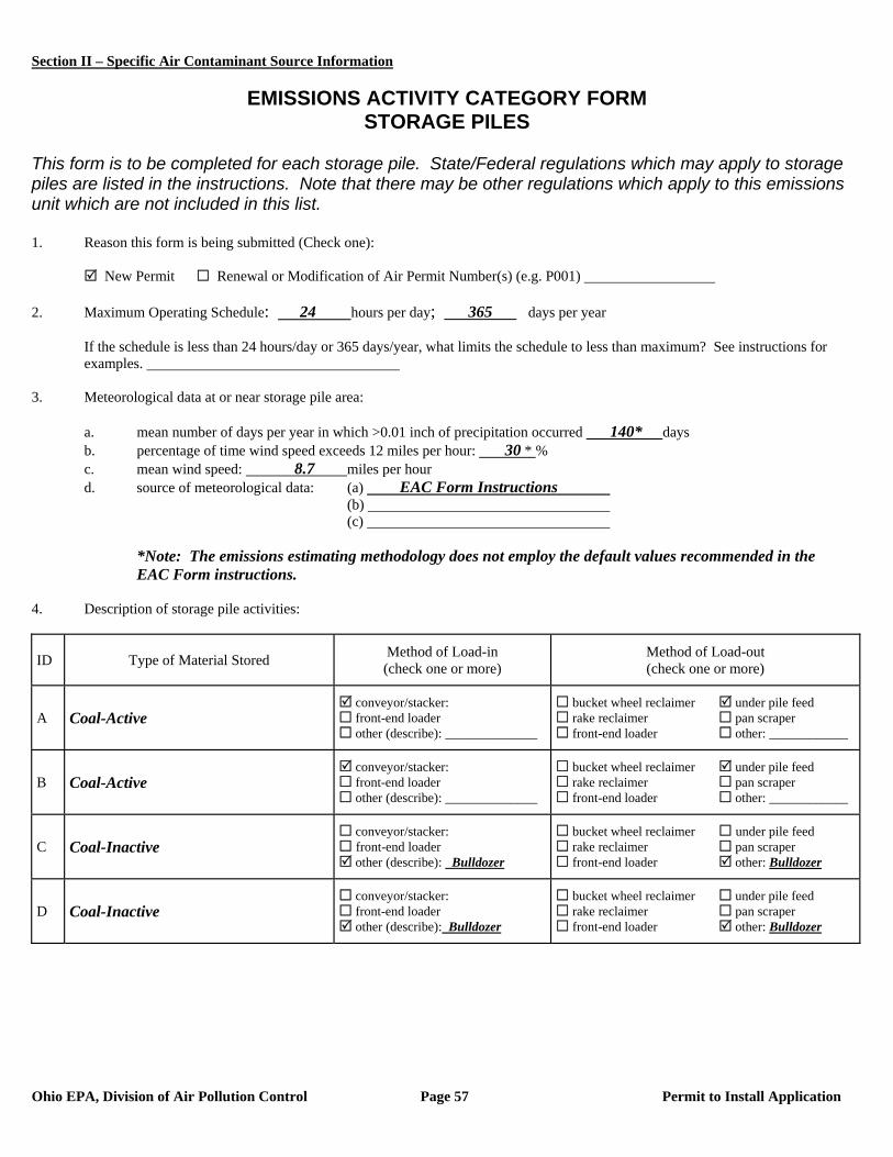
Section II – Specific Air Contaminant Source Information
Ohio EPA, Division of Air Pollution Control Page 57 Permit to Install Application
EMISSIONS ACTIVITY CATEGORY FORM
STORAGE PILES This form is to be completed for each storage pile. State/Federal regulations which may apply to storage piles are listed in the instructions. Note that there may be other regulations which apply to this emissions unit which are not included in this list. 1. Reason this form is being submitted (Check one): New Permit Renewal or Modification of Air Permit Number(s) (e.g. P001) 2. Maximum Operating Schedule: 24 hours per day; 365 days per year
If the schedule is less than 24 hours/day or 365 days/year, what limits the schedule to less than maximum? See instructions for examples.
3. Meteorological data at or near storage pile area:
a. mean number of days per year in which >0.01 inch of precipitation occurred 140* days b. percentage of time wind speed exceeds 12 miles per hour: 30 * % c. mean wind speed: 8.7 miles per hour d. source of meteorological data: (a) EAC Form Instructions
(b) (c)
*Note: The emissions estimating methodology does not employ the default values recommended in the
EAC Form instructions. 4. Description of storage pile activities:
ID Type of Material Stored Method of Load-in (check one or more)
Method of Load-out (check one or more)
A Coal-Active conveyor/stacker: front-end loader other (describe): ______________
bucket wheel reclaimer under pile feed rake reclaimer pan scraper front-end loader other: ____________
B Coal-Active conveyor/stacker: front-end loader other (describe): ______________
bucket wheel reclaimer under pile feed rake reclaimer pan scraper front-end loader other: ____________
C Coal-Inactive conveyor/stacker: front-end loader other (describe): Bulldozer
bucket wheel reclaimer under pile feed rake reclaimer pan scraper front-end loader other: Bulldozer
D Coal-Inactive conveyor/stacker: front-end loader other (describe): Bulldozer
bucket wheel reclaimer under pile feed rake reclaimer pan scraper front-end loader other: Bulldozer
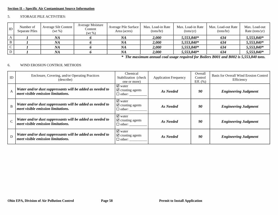
Section II – Specific Air Contaminant Source Information
Ohio EPA, Division of Air Pollution Control Page 58 Permit to Install Application
5. STORAGE PILE ACTIVITIES:
ID Number of Separate Piles
Average Silt Content (wt %)
Average Moisture Content (wt %)
Average Pile Surface Area (acres)
Max. Load-in Rate (tons/hr)
Max. Load-in Rate (tons/yr)
Max. Load-out Rate (tons/hr)
Max. Load-out Rate (tons/yr)
A 1 NA 6 NA 2,000 5,553,840* 634 5,553,840* B 1 NA 6 NA 2,000 5,553,840* 634 5,553,840* C 1 NA 6 NA 2,000 5,553,840* 634 5,553,840* D 1 NA 6 NA 2,000 5,553,840* 634 5,553,840*
* The maximum annual coal usage required for Boilers B001 and B002 is 5,553,840 tons. 6. WIND EROSION CONTROL METHODS
ID Enclosure, Covering, and/or Operating Practices (describe)
Chemical Stabilization (check
one or more) Application Frequency
Overall Control Eff. (%)
Basis for Overall Wind Erosion Control Efficiency
A Water and/or dust suppressants will be added as needed to meet visible emission limitations.
water crusting agents other: __________
As Needed 90 Engineering Judgment
B Water and/or dust suppressants will be added as needed to meet visible emission limitations.
water crusting agents other: __________
As Needed 90 Engineering Judgment
C Water and/or dust suppressants will be added as needed to meet visible emission limitations.
water crusting agents other: __________
As Needed 90 Engineering Judgment
D Water and/or dust suppressants will be added as needed to meet visible emission limitations.
water crusting agents other: __________
As Needed 90 Engineering Judgment
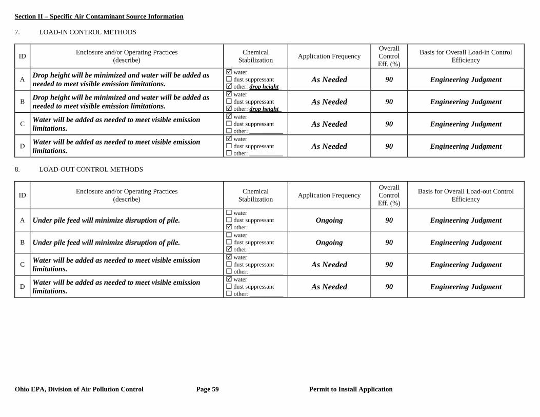
Section II – Specific Air Contaminant Source Information
Ohio EPA, Division of Air Pollution Control Page 59 Permit to Install Application
7. LOAD-IN CONTROL METHODS
ID Enclosure and/or Operating Practices (describe)
Chemical Stabilization Application Frequency
Overall Control Eff. (%)
Basis for Overall Load-in Control Efficiency
A Drop height will be minimized and water will be added as needed to meet visible emission limitations.
water dust suppressant other: drop height_
As Needed 90 Engineering Judgment
B Drop height will be minimized and water will be added as needed to meet visible emission limitations.
water dust suppressant other: drop height_
As Needed 90 Engineering Judgment
C Water will be added as needed to meet visible emission limitations.
water dust suppressant other: ___________
As Needed 90 Engineering Judgment
D Water will be added as needed to meet visible emission limitations.
water dust suppressant other: ___________
As Needed 90 Engineering Judgment
8. LOAD-OUT CONTROL METHODS
ID Enclosure and/or Operating Practices (describe)
Chemical Stabilization Application Frequency
Overall Control Eff. (%)
Basis for Overall Load-out Control Efficiency
A Under pile feed will minimize disruption of pile. water dust suppressant other: ___________
Ongoing 90 Engineering Judgment
B Under pile feed will minimize disruption of pile. water dust suppressant other: ___________
Ongoing 90 Engineering Judgment
C Water will be added as needed to meet visible emission limitations.
water dust suppressant other: ___________
As Needed 90 Engineering Judgment
D Water will be added as needed to meet visible emission limitations.
water dust suppressant other: ___________
As Needed 90 Engineering Judgment
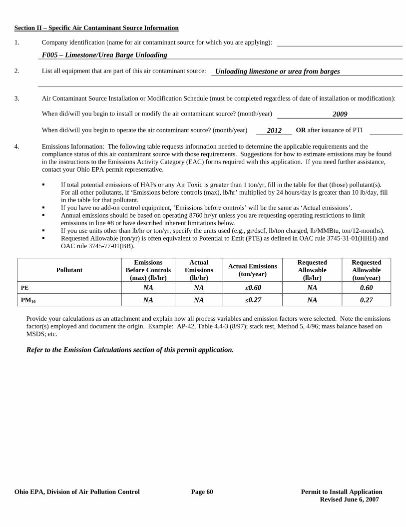
Section II – Specific Air Contaminant Source Information
Ohio EPA, Division of Air Pollution Control Page 60 Permit to Install Application Revised June 6, 2007
1. Company identification (name for air contaminant source for which you are applying):
F005 – Limestone/Urea Barge Unloading 2. List all equipment that are part of this air contaminant source: Unloading limestone or urea from barges 3. Air Contaminant Source Installation or Modification Schedule (must be completed regardless of date of installation or modification): When did/will you begin to install or modify the air contaminant source? (month/year) 2009 When did/will you begin to operate the air contaminant source? (month/year) 2012 OR after issuance of PTI 4. Emissions Information: The following table requests information needed to determine the applicable requirements and the compliance status of this air contaminant source with those requirements. Suggestions for how to estimate emissions may be found in the instructions to the Emissions Activity Category (EAC) forms required with this application. If you need further assistance, contact your Ohio EPA permit representative.
If total potential emissions of HAPs or any Air Toxic is greater than 1 ton/yr, fill in the table for that (those) pollutant(s).
For all other pollutants, if ‘Emissions before controls (max), lb/hr’ multiplied by 24 hours/day is greater than 10 lb/day, fill in the table for that pollutant.
If you have no add-on control equipment, ‘Emissions before controls’ will be the same as ‘Actual emissions’. Annual emissions should be based on operating 8760 hr/yr unless you are requesting operating restrictions to limit
emissions in line #8 or have described inherent limitations below. If you use units other than lb/hr or ton/yr, specify the units used (e.g., gr/dscf, lb/ton charged, lb/MMBtu, ton/12-months). Requested Allowable (ton/yr) is often equivalent to Potential to Emit (PTE) as defined in OAC rule 3745-31-01(HHH) and
OAC rule 3745-77-01(BB).
Pollutant Emissions
Before Controls (max) (lb/hr)
Actual Emissions
(lb/hr)
Actual Emissions (ton/year)
Requested Allowable
(lb/hr)
Requested Allowable (ton/year)
PE NA NA #0.60 NA 0.60
PM10 NA NA #0.27 NA 0.27
Provide your calculations as an attachment and explain how all process variables and emission factors were selected. Note the emissions factor(s) employed and document the origin. Example: AP-42, Table 4.4-3 (8/97); stack test, Method 5, 4/96; mass balance based on MSDS; etc.
Refer to the Emission Calculations section of this permit application.
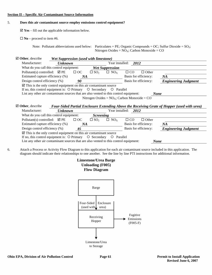
Section II – Specific Air Contaminant Source Information
Ohio EPA, Division of Air Pollution Control Page 61 Permit to Install Application Revised June 6, 2007
5. Does this air contaminant source employ emissions control equipment? Yes – fill out the applicable information below. No – proceed to item #6. Note: Pollutant abbreviations used below: Particulates = PE; Organic Compounds = OC; Sulfur Dioxide = SO2; Nitrogen Oxides = NOX; Carbon Monoxide = CO
Other, describe Wet Suppression (used with limestone) Manufacturer: Unknown Year installed: 2012 What do you call this control equipment: Wet Suppression Pollutant(s) controlled: PE OC SO2 NOX CO Other Estimated capture efficiency (%) NA Basis for efficiency: NA Design control efficiency (%) 90 Basis for efficiency: Engineering Judgment This is the only control equipment on this air contaminant source If no, this control equipment is: Primary Secondary Parallel List any other air contaminant sources that are also vented to this control equipment: None
Nitrogen Oxides = NOX; Carbon Monoxide = CO
Other, describe Four-Sided Partial Enclosure Extending Above the Receiving Grate of Hopper (used with urea) Manufacturer: Unknown Year installed: 2012 What do you call this control equipment: Screening Pollutant(s) controlled: PE OC SO2 NOX CO Other Estimated capture efficiency (%) NA Basis for efficiency: NA Design control efficiency (%) 85 Basis for efficiency: Engineering Judgment This is the only control equipment on this air contaminant source If no, this control equipment is: Primary Secondary Parallel List any other air contaminant sources that are also vented to this control equipment: None
6. Attach a Process or Activity Flow Diagram to this application for each air contaminant source included in this application. The
diagram should indicate their relationships to one another. See the line by line PTI instructions for additional information.
Barge
ReceivingHopper
Limestone/Ureato Storage
Limestone/Urea Barge Unloading (F005)
Flow Diagram
Fugitive Emissions(F005-F)
Four-Sided Enclosure (used with urea)
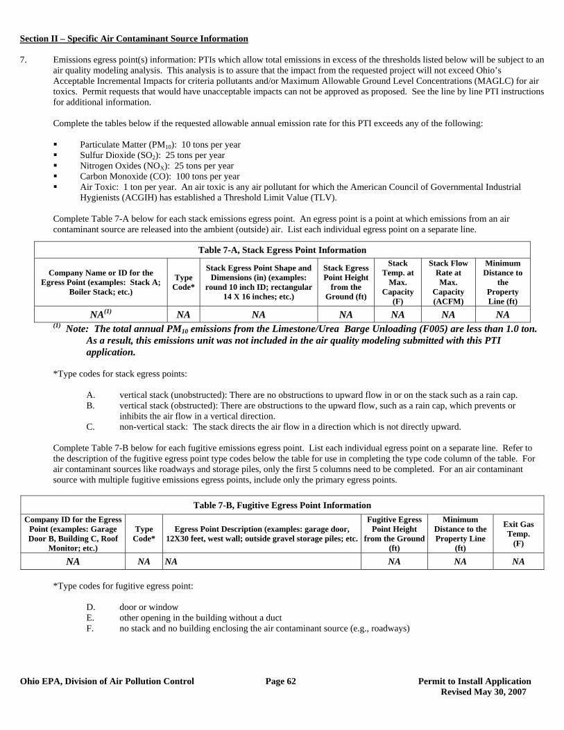
Section II – Specific Air Contaminant Source Information
Ohio EPA, Division of Air Pollution Control Page 62 Permit to Install Application Revised May 30, 2007
7. Emissions egress point(s) information: PTIs which allow total emissions in excess of the thresholds listed below will be subject to an
air quality modeling analysis. This analysis is to assure that the impact from the requested project will not exceed Ohio’s Acceptable Incremental Impacts for criteria pollutants and/or Maximum Allowable Ground Level Concentrations (MAGLC) for air toxics. Permit requests that would have unacceptable impacts can not be approved as proposed. See the line by line PTI instructions for additional information.
Complete the tables below if the requested allowable annual emission rate for this PTI exceeds any of the following:
Particulate Matter (PM10): 10 tons per year Sulfur Dioxide (SO2): 25 tons per year Nitrogen Oxides (NOX): 25 tons per year Carbon Monoxide (CO): 100 tons per year Air Toxic: 1 ton per year. An air toxic is any air pollutant for which the American Council of Governmental Industrial
Hygienists (ACGIH) has established a Threshold Limit Value (TLV).
Complete Table 7-A below for each stack emissions egress point. An egress point is a point at which emissions from an air contaminant source are released into the ambient (outside) air. List each individual egress point on a separate line.
(1) Note: The total annual PM10 emissions from the Limestone/Urea Barge Unloading (F005) are less than 1.0 ton. As a result, this emissions unit was not included in the air quality modeling submitted with this PTI application.
*Type codes for stack egress points:
A. vertical stack (unobstructed): There are no obstructions to upward flow in or on the stack such as a rain cap. B. vertical stack (obstructed): There are obstructions to the upward flow, such as a rain cap, which prevents or
inhibits the air flow in a vertical direction. C. non-vertical stack: The stack directs the air flow in a direction which is not directly upward.
Complete Table 7-B below for each fugitive emissions egress point. List each individual egress point on a separate line. Refer to the description of the fugitive egress point type codes below the table for use in completing the type code column of the table. For air contaminant sources like roadways and storage piles, only the first 5 columns need to be completed. For an air contaminant source with multiple fugitive emissions egress points, include only the primary egress points.
Table 7-B, Fugitive Egress Point Information
Company ID for the Egress Point (examples: Garage Door B, Building C, Roof
Monitor; etc.)
Type Code*
Egress Point Description (examples: garage door, 12X30 feet, west wall; outside gravel storage piles; etc.
Fugitive Egress Point Height
from the Ground (ft)
Minimum Distance to the Property Line
(ft)
Exit Gas Temp.
(F)
NA NA NA NA NA NA
*Type codes for fugitive egress point:
D. door or window E. other opening in the building without a duct F. no stack and no building enclosing the air contaminant source (e.g., roadways)
Table 7-A, Stack Egress Point Information
Company Name or ID for the Egress Point (examples: Stack A;
Boiler Stack; etc.)
Type Code*
Stack Egress Point Shape and Dimensions (in) (examples:
round 10 inch ID; rectangular 14 X 16 inches; etc.)
Stack Egress Point Height
from the Ground (ft)
Stack Temp. at
Max. Capacity
(F)
Stack Flow Rate at Max.
Capacity (ACFM)
Minimum Distance to
the Property Line (ft)
NA(1) NA NA NA NA NA NA

Section II – Specific Air Contaminant Source Information
Ohio EPA, Division of Air Pollution Control Page 63 Permit to Install Application Revised May 30, 2007
Complete Table 7-C below for each Stack Egress Point identified in Table 7-A above. In each case, use the dimensions of the largest nearby building segment or structure. List each individual egress point on a separate line. Use the same Company Name or ID for the Egress Point in Table 7-C that was used in Table 7-A. See the line by line PTI instructions for additional information.
Table 7-C, Egress Point Additional Information Table 7-C, Continued
Company ID or Name for the Egress
Point
Building Height (ft)
Building Width (ft)
Building Length (ft)
Company ID or Name for the Egress
Point
Building Height (ft)
Building Width (ft)
Building Length (ft)
NA NA NA NA 8. Request for Federally Enforceable Limits
As part of this permit application, do you wish to propose voluntary restrictions to limit emissions in order to avoid specific requirements list below, (i.e., are you requesting federally enforceable limits to obtain synthetic minor status)?
Yes No Not Sure – Please contact me if this affects me.
If yes, why are you requesting federally enforceable limits? Check all that apply. a. to avoid being a “major source” (see OAC rule 3745-77-01(W)) b. to avoid being a “major MACT source” (see OAC rule 3745-31-01(QQ)) c. to avoid being a “major modification” (see OAC rule 3745-31-01(RR)) d. to avoid being a “major stationary source” (see OAC rule 3745-31-01(SS)) e. to avoid an air dispersion modeling requirement (see Engineering Guide #69) f. to avoid another requirement. Describe: If you checked a., b. or d., please attach a facility-wide potential to emit (PTE) analysis (for each pollutant) and synthetic minor strategy to this application. (See line by line instructions for definition of PTE.) If you checked c., please attach a net emission change analysis to this application.
9. If this air contaminant source utilizes any continuous emissions monitoring equipment for indicating or demonstrating compliance, complete the following table. This does not include continuous parametric monitoring systems.
Company ID for Egress Point Type of Monitor
Applicable Performance Specification (40 CFR 60,
Appendix B) Pollutant(s) Monitored
None
10. Do you wish to permit this air contaminant source as a portable source, allowing relocation within the state in accordance with OAC
rule 3745-31-03(A)(1)(p) or OAC rule 3745-31-05(F)?
Yes – Note: notification requirements in rules cited above must be followed. No
11. The appropriate Emissions Activity Category (EAC) form(s) must be completed and attached for each air contaminant source. At
least one complete EAC form must be submitted for each air contaminant source for the application to be considered complete. Refer to the list attached to the PTI instructions. See attached General Process Operation EAC Form for emissions unit F005.
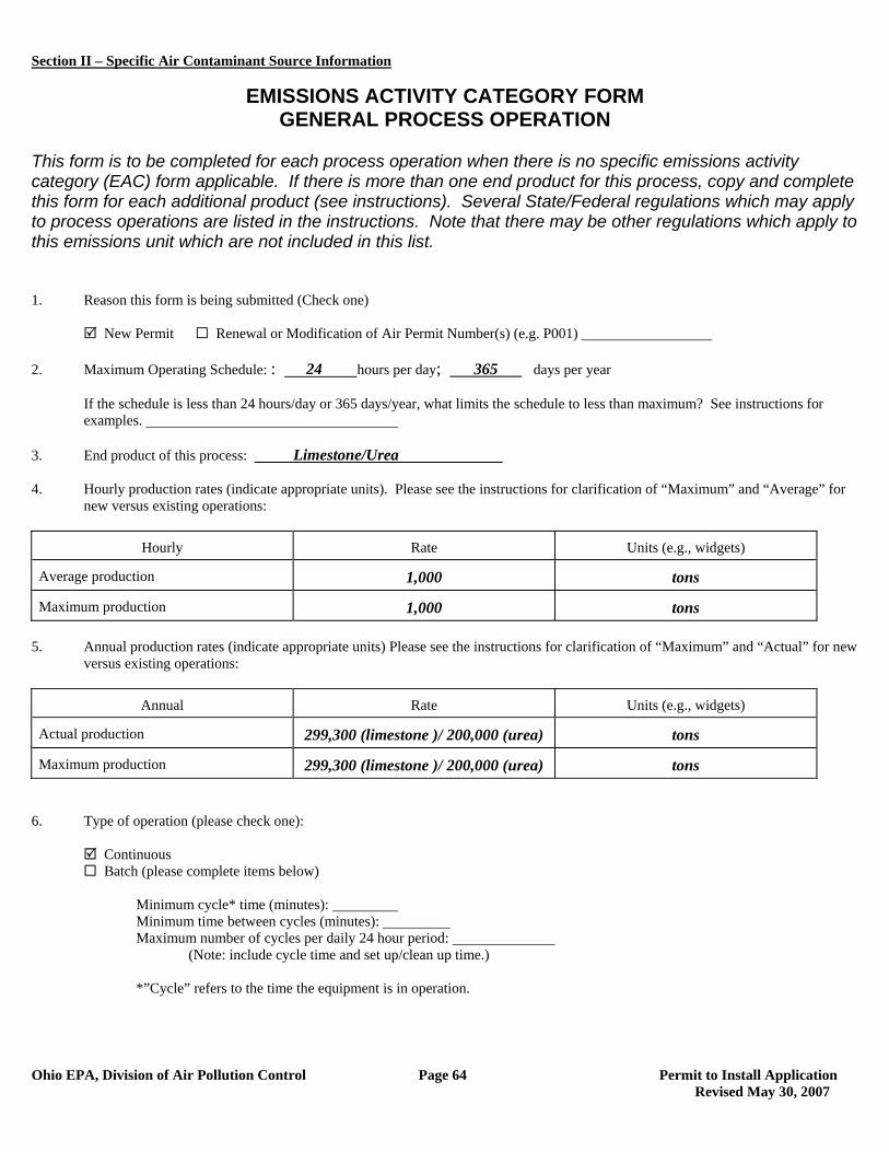
Section II – Specific Air Contaminant Source Information
Ohio EPA, Division of Air Pollution Control Page 64 Permit to Install Application Revised May 30, 2007
EMISSIONS ACTIVITY CATEGORY FORM GENERAL PROCESS OPERATION
This form is to be completed for each process operation when there is no specific emissions activity category (EAC) form applicable. If there is more than one end product for this process, copy and complete this form for each additional product (see instructions). Several State/Federal regulations which may apply to process operations are listed in the instructions. Note that there may be other regulations which apply to this emissions unit which are not included in this list. 1. Reason this form is being submitted (Check one) New Permit Renewal or Modification of Air Permit Number(s) (e.g. P001) 2. Maximum Operating Schedule: : 24 hours per day; 365 days per year
If the schedule is less than 24 hours/day or 365 days/year, what limits the schedule to less than maximum? See instructions for examples.
3. End product of this process: Limestone/Urea 4. Hourly production rates (indicate appropriate units). Please see the instructions for clarification of “Maximum” and “Average” for
new versus existing operations:
Hourly Rate Units (e.g., widgets)
Average production 1,000 tons
Maximum production 1,000 tons 5. Annual production rates (indicate appropriate units) Please see the instructions for clarification of “Maximum” and “Actual” for new
versus existing operations:
Annual Rate Units (e.g., widgets)
Actual production 299,300 (limestone )/ 200,000 (urea) tons
Maximum production 299,300 (limestone )/ 200,000 (urea) tons 6. Type of operation (please check one):
Continuous Batch (please complete items below)
Minimum cycle* time (minutes): Minimum time between cycles (minutes): Maximum number of cycles per daily 24 hour period:
(Note: include cycle time and set up/clean up time.) *”Cycle” refers to the time the equipment is in operation.
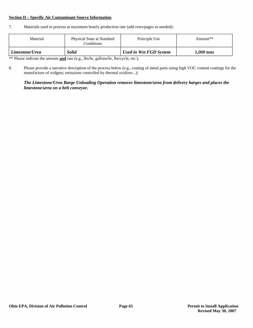
Section II – Specific Air Contaminant Source Information
Ohio EPA, Division of Air Pollution Control Page 65 Permit to Install Application Revised May 30, 2007
7. Materials used in process at maximum hourly production rate (add rows/pages as needed):
Material Physical State at Standard Conditions
Principle Use Amount**
Limestone/Urea Solid Used in Wet FGD System 1,000 tons ** Please indicate the amount and rate (e.g., lbs/hr, gallons/hr, lbs/cycle, etc.). 8. Please provide a narrative description of the process below (e.g., coating of metal parts using high VOC content coatings for the
manufacture of widgets; emissions controlled by thermal oxidizer...): The Limestone/Urea Barge Unloading Operation removes limestone/urea from delivery barges and places the
limestone/urea on a belt conveyor.
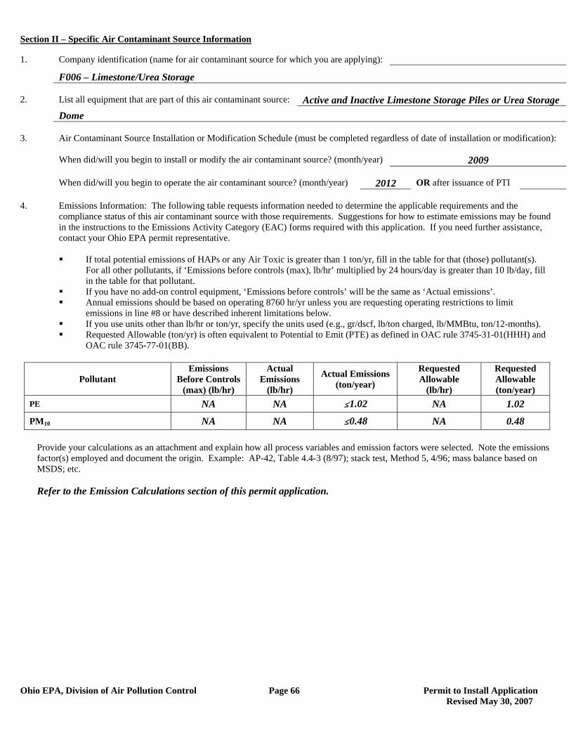
Section II – Specific Air Contaminant Source Information
Ohio EPA, Division of Air Pollution Control Page 66 Permit to Install Application Revised May 30, 2007
1. Company identification (name for air contaminant source for which you are applying):
F006 – Limestone/Urea Storage 2. List all equipment that are part of this air contaminant source: Active and Inactive Limestone Storage Piles or Urea Storage Dome 3. Air Contaminant Source Installation or Modification Schedule (must be completed regardless of date of installation or modification): When did/will you begin to install or modify the air contaminant source? (month/year) 2009 When did/will you begin to operate the air contaminant source? (month/year) 2012 OR after issuance of PTI 4. Emissions Information: The following table requests information needed to determine the applicable requirements and the compliance status of this air contaminant source with those requirements. Suggestions for how to estimate emissions may be found in the instructions to the Emissions Activity Category (EAC) forms required with this application. If you need further assistance, contact your Ohio EPA permit representative.
If total potential emissions of HAPs or any Air Toxic is greater than 1 ton/yr, fill in the table for that (those) pollutant(s).
For all other pollutants, if ‘Emissions before controls (max), lb/hr’ multiplied by 24 hours/day is greater than 10 lb/day, fill in the table for that pollutant.
If you have no add-on control equipment, ‘Emissions before controls’ will be the same as ‘Actual emissions’. Annual emissions should be based on operating 8760 hr/yr unless you are requesting operating restrictions to limit
emissions in line #8 or have described inherent limitations below. If you use units other than lb/hr or ton/yr, specify the units used (e.g., gr/dscf, lb/ton charged, lb/MMBtu, ton/12-months). Requested Allowable (ton/yr) is often equivalent to Potential to Emit (PTE) as defined in OAC rule 3745-31-01(HHH) and
OAC rule 3745-77-01(BB).
Pollutant Emissions
Before Controls (max) (lb/hr)
Actual Emissions
(lb/hr)
Actual Emissions (ton/year)
Requested Allowable
(lb/hr)
Requested Allowable (ton/year)
PE NA NA #1.02 NA 1.02
PM10 NA NA #0.48 NA 0.48
Provide your calculations as an attachment and explain how all process variables and emission factors were selected. Note the emissions factor(s) employed and document the origin. Example: AP-42, Table 4.4-3 (8/97); stack test, Method 5, 4/96; mass balance based on MSDS; etc.
Refer to the Emission Calculations section of this permit application.
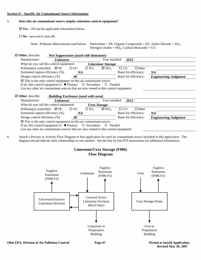
Section II – Specific Air Contaminant Source Information
Ohio EPA, Division of Air Pollution Control Page 67 Permit to Install Application Revised May 30, 2007
5. Does this air contaminant source employ emissions control equipment? Yes – fill out the applicable information below. No – proceed to item #6. Note: Pollutant abbreviations used below: Particulates = PE; Organic Compounds = OC; Sulfur Dioxide = SO2; Nitrogen Oxides = NOX; Carbon Monoxide = CO
Other, describe Wet Suppression (used with limestone) Manufacturer: Unknown Year installed: 2012 What do you call this control equipment: Limestone Storage Pollutant(s) controlled: PE OC SO2 NOX CO Other Estimated capture efficiency (%) NA Basis for efficiency: NA Design control efficiency (%) 90 Basis for efficiency: Engineering Judgment This is the only control equipment on this air contaminant source If no, this control equipment is: Primary Secondary Parallel List any other air contaminant sources that are also vented to this control equipment:
Other, describe Building Enclosure (used with urea)
Manufacturer: Unknown Year installed: 2012 What do you call this control equipment: Urea Storage Pollutant(s) controlled: PE OC SO2 NOX CO Other Estimated capture efficiency (%) NA Basis for efficiency: NA Design control efficiency (%) 90 Basis for efficiency: Engineering Judgment This is the only control equipment on this air contaminant source If no, this control equipment is: Primary Secondary Parallel List any other air contaminant sources that are also vented to this control equipment:
6. Attach a Process or Activity Flow Diagram to this application for each air contaminant source included in this application. The
diagram should indicate their relationships to one another. See the line by line PTI instructions for additional information.
Covered ActiveLimestone Stockout
(Roof Only)
Limestone/Urea Storage (F006)Flow Diagram
Fugitive Emissions(F006-F1)
Uncovered InactiveLimestone Stockout
Limestone to Preparation
Building
LimestoneFugitive
Emissions(F006-F2)
Urea Storage Dome
Fugitive Emissions(F006-F1)
Urea to Preparation
Building
Urea
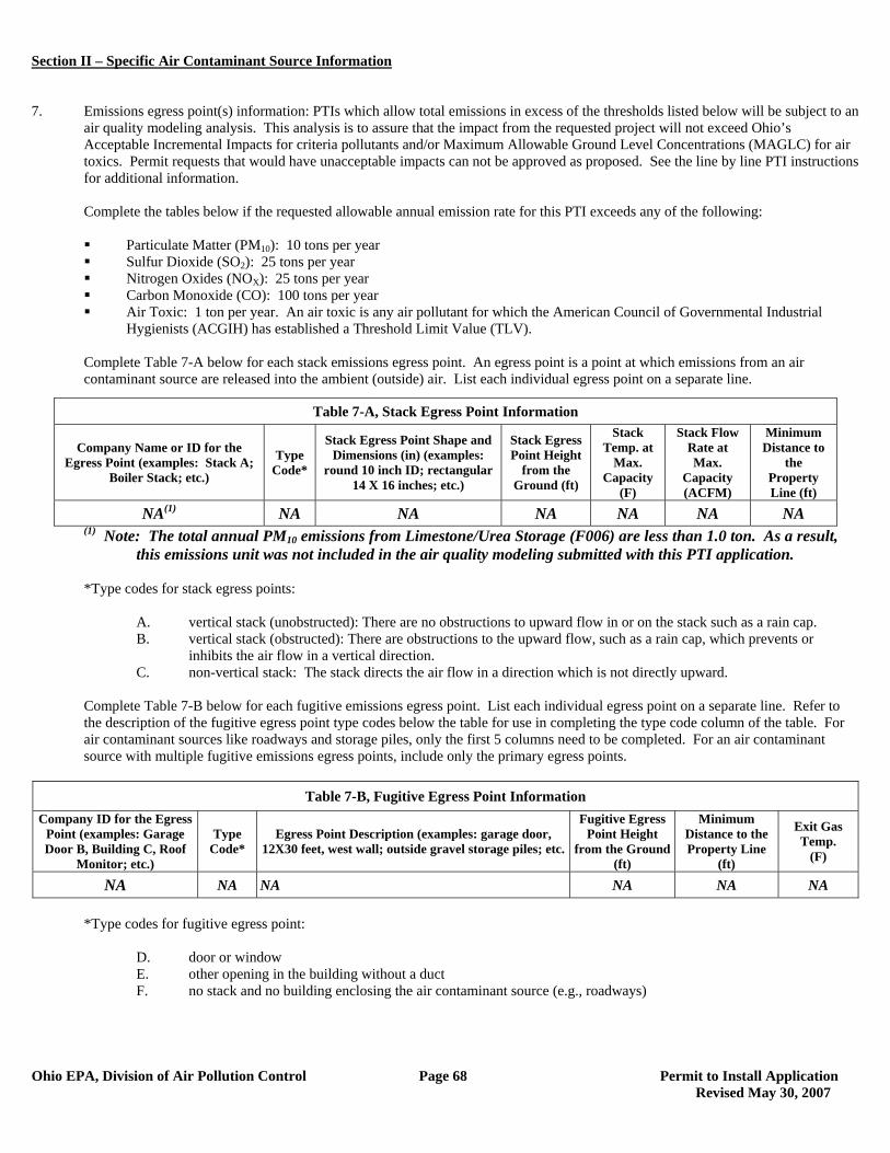
Section II – Specific Air Contaminant Source Information
Ohio EPA, Division of Air Pollution Control Page 68 Permit to Install Application Revised May 30, 2007
7. Emissions egress point(s) information: PTIs which allow total emissions in excess of the thresholds listed below will be subject to an
air quality modeling analysis. This analysis is to assure that the impact from the requested project will not exceed Ohio’s Acceptable Incremental Impacts for criteria pollutants and/or Maximum Allowable Ground Level Concentrations (MAGLC) for air toxics. Permit requests that would have unacceptable impacts can not be approved as proposed. See the line by line PTI instructions for additional information.
Complete the tables below if the requested allowable annual emission rate for this PTI exceeds any of the following:
Particulate Matter (PM10): 10 tons per year Sulfur Dioxide (SO2): 25 tons per year Nitrogen Oxides (NOX): 25 tons per year Carbon Monoxide (CO): 100 tons per year Air Toxic: 1 ton per year. An air toxic is any air pollutant for which the American Council of Governmental Industrial
Hygienists (ACGIH) has established a Threshold Limit Value (TLV).
Complete Table 7-A below for each stack emissions egress point. An egress point is a point at which emissions from an air contaminant source are released into the ambient (outside) air. List each individual egress point on a separate line.
(1) Note: The total annual PM10 emissions from Limestone/Urea Storage (F006) are less than 1.0 ton. As a result, this emissions unit was not included in the air quality modeling submitted with this PTI application.
*Type codes for stack egress points:
A. vertical stack (unobstructed): There are no obstructions to upward flow in or on the stack such as a rain cap. B. vertical stack (obstructed): There are obstructions to the upward flow, such as a rain cap, which prevents or
inhibits the air flow in a vertical direction. C. non-vertical stack: The stack directs the air flow in a direction which is not directly upward.
Complete Table 7-B below for each fugitive emissions egress point. List each individual egress point on a separate line. Refer to the description of the fugitive egress point type codes below the table for use in completing the type code column of the table. For air contaminant sources like roadways and storage piles, only the first 5 columns need to be completed. For an air contaminant source with multiple fugitive emissions egress points, include only the primary egress points.
Table 7-B, Fugitive Egress Point Information
Company ID for the Egress Point (examples: Garage Door B, Building C, Roof
Monitor; etc.)
Type Code*
Egress Point Description (examples: garage door, 12X30 feet, west wall; outside gravel storage piles; etc.
Fugitive Egress Point Height
from the Ground (ft)
Minimum Distance to the Property Line
(ft)
Exit Gas Temp.
(F)
NA NA NA NA NA NA
*Type codes for fugitive egress point:
D. door or window E. other opening in the building without a duct F. no stack and no building enclosing the air contaminant source (e.g., roadways)
Table 7-A, Stack Egress Point Information
Company Name or ID for the Egress Point (examples: Stack A;
Boiler Stack; etc.)
Type Code*
Stack Egress Point Shape and Dimensions (in) (examples:
round 10 inch ID; rectangular 14 X 16 inches; etc.)
Stack Egress Point Height
from the Ground (ft)
Stack Temp. at
Max. Capacity
(F)
Stack Flow Rate at Max.
Capacity (ACFM)
Minimum Distance to
the Property Line (ft)
NA(1) NA NA NA NA NA NA
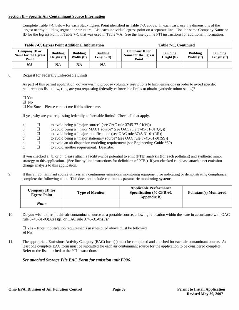
Section II – Specific Air Contaminant Source Information
Ohio EPA, Division of Air Pollution Control Page 69 Permit to Install Application Revised May 30, 2007
Complete Table 7-C below for each Stack Egress Point identified in Table 7-A above. In each case, use the dimensions of the largest nearby building segment or structure. List each individual egress point on a separate line. Use the same Company Name or ID for the Egress Point in Table 7-C that was used in Table 7-A. See the line by line PTI instructions for additional information.
Table 7-C, Egress Point Additional Information Table 7-C, Continued
Company ID or Name for the Egress
Point
Building Height (ft)
Building Width (ft)
Building Length (ft)
Company ID or Name for the Egress
Point
Building Height (ft)
Building Width (ft)
Building Length (ft)
NA NA NA NA 8. Request for Federally Enforceable Limits
As part of this permit application, do you wish to propose voluntary restrictions to limit emissions in order to avoid specific requirements list below, (i.e., are you requesting federally enforceable limits to obtain synthetic minor status)?
Yes No Not Sure – Please contact me if this affects me.
If yes, why are you requesting federally enforceable limits? Check all that apply. a. to avoid being a “major source” (see OAC rule 3745-77-01(W)) b. to avoid being a “major MACT source” (see OAC rule 3745-31-01(QQ)) c. to avoid being a “major modification” (see OAC rule 3745-31-01(RR)) d. to avoid being a “major stationary source” (see OAC rule 3745-31-01(SS)) e. to avoid an air dispersion modeling requirement (see Engineering Guide #69) f. to avoid another requirement. Describe: If you checked a., b. or d., please attach a facility-wide potential to emit (PTE) analysis (for each pollutant) and synthetic minor strategy to this application. (See line by line instructions for definition of PTE.) If you checked c., please attach a net emission change analysis to this application.
9. If this air contaminant source utilizes any continuous emissions monitoring equipment for indicating or demonstrating compliance, complete the following table. This does not include continuous parametric monitoring systems.
Company ID for Egress Point Type of Monitor
Applicable Performance Specification (40 CFR 60,
Appendix B) Pollutant(s) Monitored
None
10. Do you wish to permit this air contaminant source as a portable source, allowing relocation within the state in accordance with OAC
rule 3745-31-03(A)(1)(p) or OAC rule 3745-31-05(F)?
Yes – Note: notification requirements in rules cited above must be followed. No
11. The appropriate Emissions Activity Category (EAC) form(s) must be completed and attached for each air contaminant source. At
least one complete EAC form must be submitted for each air contaminant source for the application to be considered complete. Refer to the list attached to the PTI instructions. See attached Storage Pile EAC Form for emission unit F006.
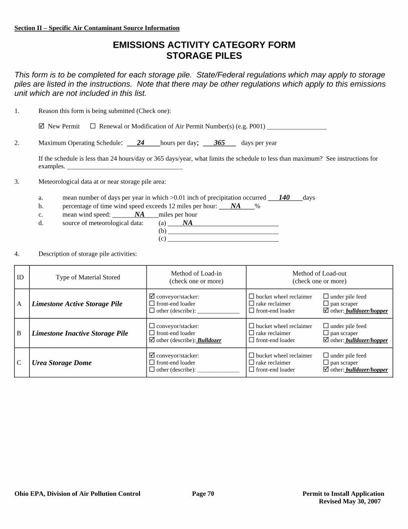
Section II – Specific Air Contaminant Source Information
Ohio EPA, Division of Air Pollution Control Page 70 Permit to Install Application Revised May 30, 2007
EMISSIONS ACTIVITY CATEGORY FORM
STORAGE PILES This form is to be completed for each storage pile. State/Federal regulations which may apply to storage piles are listed in the instructions. Note that there may be other regulations which apply to this emissions unit which are not included in this list. 1. Reason this form is being submitted (Check one): New Permit Renewal or Modification of Air Permit Number(s) (e.g. P001) 2. Maximum Operating Schedule: 24 hours per day; 365 days per year
If the schedule is less than 24 hours/day or 365 days/year, what limits the schedule to less than maximum? See instructions for examples.
3. Meteorological data at or near storage pile area:
a. mean number of days per year in which >0.01 inch of precipitation occurred 140 days b. percentage of time wind speed exceeds 12 miles per hour: NA % c. mean wind speed: NA miles per hour d. source of meteorological data: (a) NA
(b) (c)
4. Description of storage pile activities:
ID Type of Material Stored Method of Load-in (check one or more)
Method of Load-out (check one or more)
A Limestone Active Storage Pile conveyor/stacker: front-end loader other (describe): ______________
bucket wheel reclaimer under pile feed rake reclaimer pan scraper front-end loader other: bulldozer/hopper
B Limestone Inactive Storage Pile conveyor/stacker: front-end loader other (describe): Bulldozer
bucket wheel reclaimer under pile feed rake reclaimer pan scraper front-end loader other: bulldozer/hopper
C Urea Storage Dome conveyor/stacker: front-end loader other (describe): ______________
bucket wheel reclaimer under pile feed rake reclaimer pan scraper front-end loader other: bulldozer/hopper
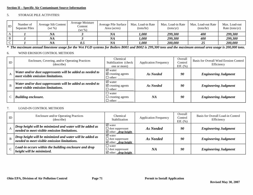
Section II – Specific Air Contaminant Source Information
Ohio EPA, Division of Air Pollution Control Page 71 Permit to Install Application Revised May 30, 2007
5. STORAGE PILE ACTIVITIES:
ID Number of Separate Piles
Average Silt Content (wt %)
Average Moisture Content (wt %)
Average Pile Surface Area (acres)
Max. Load-in Rate (tons/hr)
Max. Load-in Rate (tons/yr)
Max. Load-out Rate (tons/hr)
Max. Load-out Rate (tons/yr)
A 1 NA 3 NA 1,000 299,300 400 299,300 B 1 NA 3 NA 1,000 299,300 400 299,300 C 1 NA 0.5 NA 1,000 200,000 25 200,000
* The maximum annual limestone usage for the Wet FGD systems for Boilers B001 and B002 is 299,300 tons and the maximum annual urea usage is 200,000 tons. 6. WIND EROSION CONTROL METHODS
ID Enclosure, Covering, and/or Operating Practices (describe)
Chemical Stabilization (check
one or more) Application Frequency
Overall Control Eff. (%)
Basis for Overall Wind Erosion Control Efficiency
A Water and/or dust suppressants will be added as needed to meet visible emission limitations.
water crusting agents other: __________
As Needed 90 Engineering Judgment
B Water and/or dust suppressants will be added as needed to meet visible emission limitations.
water crusting agents other: __________
As Needed 90 Engineering Judgment
C Building enclosure. water crusting agents other: __________
NA 90 Engineering Judgment
7. LOAD-IN CONTROL METHODS
ID Enclosure and/or Operating Practices (describe)
Chemical Stabilization Application Frequency
Overall Control Eff. (%)
Basis for Overall Load-in Control Efficiency
A Drop height will be minimized and water will be added as needed to meet visible emission limitations.
water dust suppressant other: _drop height_
As Needed 90 Engineering Judgment
B Drop height will be minimized and water will be added as needed to meet visible emission limitations.
water dust suppressant other: _drop height_
As Needed 90 Engineering Judgment
C Load-in occurs within the building enclosure and drop height will be minimized.
water dust suppressant other: _drop height_
NA 90 Engineering Judgment
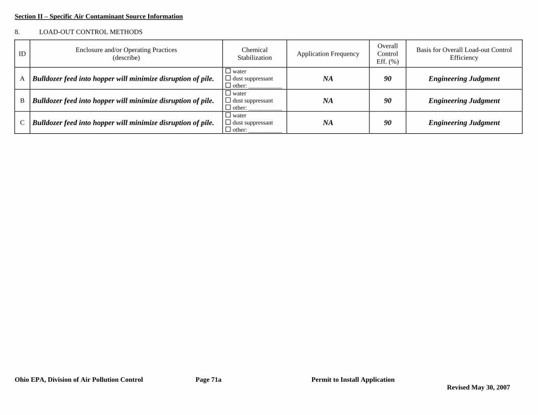
Section II – Specific Air Contaminant Source Information
Ohio EPA, Division of Air Pollution Control Page 71a Permit to Install Application Revised May 30, 2007
8. LOAD-OUT CONTROL METHODS
ID Enclosure and/or Operating Practices (describe)
Chemical Stabilization Application Frequency
Overall Control Eff. (%)
Basis for Overall Load-out Control Efficiency
A Bulldozer feed into hopper will minimize disruption of pile. water dust suppressant other: ___________
NA 90 Engineering Judgment
B Bulldozer feed into hopper will minimize disruption of pile. water dust suppressant other: ___________
NA 90 Engineering Judgment
C Bulldozer feed into hopper will minimize disruption of pile. water dust suppressant other: ___________
NA 90 Engineering Judgment

Section II – Specific Air Contaminant Source Information
Ohio EPA, Division of Air Pollution Control Page 72 Permit to Install Application
1. Company identification (name for air contaminant source for which you are applying):
P001- Cooling Cells for Boiler B001 2. List all equipment that are part of this air contaminant source: Cooling Cells for B001 (16 integrated cooling cells) 3. Air Contaminant Source Installation or Modification Schedule (must be completed regardless of date of installation or modification): When did/will you begin to install or modify the air contaminant source? (month/year) 2009 When did/will you begin to operate the air contaminant source? (month/year) 2012 OR after issuance of PTI 4. Emissions Information: The following table requests information needed to determine the applicable requirements and the compliance status of this air contaminant source with those requirements. Suggestions for how to estimate emissions may be found in the instructions to the Emissions Activity Category (EAC) forms required with this application. If you need further assistance, contact your Ohio EPA permit representative.
If total potential emissions of HAPs or any Air Toxic is greater than 1 ton/yr, fill in the table for that (those) pollutant(s).
For all other pollutants, if ‘Emissions before controls (max), lb/hr’ multiplied by 24 hours/day is greater than 10 lb/day, fill in the table for that pollutant.
If you have no add-on control equipment, ‘Emissions before controls’ will be the same as ‘Actual emissions’. Annual emissions should be based on operating 8760 hr/yr unless you are requesting operating restrictions to limit
emissions in line #8 or have described inherent limitations below. If you use units other than lb/hr or ton/yr, specify the units used (e.g., gr/dscf, lb/ton charged, lb/MMBtu, ton/12-months). Requested Allowable (ton/yr) is often equivalent to Potential to Emit (PTE) as defined in OAC rule 3745-31-01(HHH) and
OAC rule 3745-77-01(BB).
Pollutant Emissions
Before Controls (max) (lb/hr)
Actual Emissions
(lb/hr)
Actual Emissions (ton/year)
Requested Allowable
(lb/hr)
Requested Allowable (ton/year)
PE NA #0.17 #0.77 0.17 0.77
PM10 NA #0.17 #0.77 0.17 0.77
Provide your calculations as an attachment and explain how all process variables and emission factors were selected. Note the emissions factor(s) employed and document the origin. Example: AP-42, Table 4.4-3 (8/97); stack test, Method 5, 4/96; mass balance based on MSDS; etc.
Refer to the Emission Calculations section of this permit application.
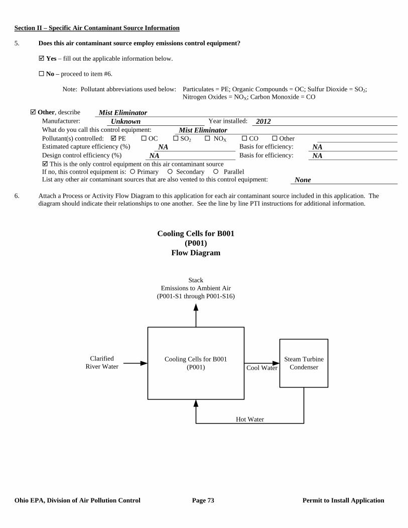
Section II – Specific Air Contaminant Source Information
Ohio EPA, Division of Air Pollution Control Page 73 Permit to Install Application
5. Does this air contaminant source employ emissions control equipment? Yes – fill out the applicable information below. No – proceed to item #6. Note: Pollutant abbreviations used below: Particulates = PE; Organic Compounds = OC; Sulfur Dioxide = SO2; Nitrogen Oxides = NOX; Carbon Monoxide = CO
Other, describe Mist Eliminator Manufacturer: Unknown Year installed: 2012 What do you call this control equipment: Mist Eliminator Pollutant(s) controlled: PE OC SO2 NOX CO Other Estimated capture efficiency (%) NA Basis for efficiency: NA Design control efficiency (%) NA Basis for efficiency: NA This is the only control equipment on this air contaminant source If no, this control equipment is: Primary Secondary Parallel List any other air contaminant sources that are also vented to this control equipment: None
6. Attach a Process or Activity Flow Diagram to this application for each air contaminant source included in this application. The
diagram should indicate their relationships to one another. See the line by line PTI instructions for additional information.
Cooling Cells for B001(P001)
Clarified River Water
StackEmissions to Ambient Air
(P001-S1 through P001-S16)
Hot Water
Cooling Cells for B001(P001)
Flow Diagram
Steam Turbine CondenserCool Water

Section II – Specific Air Contaminant Source Information
Ohio EPA, Division of Air Pollution Control Page 74 Permit to Install Application
7. Emissions egress point(s) information: PTIs which allow total emissions in excess of the thresholds listed below will be subject to an
air quality modeling analysis. This analysis is to assure that the impact from the requested project will not exceed Ohio’s Acceptable Incremental Impacts for criteria pollutants and/or Maximum Allowable Ground Level Concentrations (MAGLC) for air toxics. Permit requests that would have unacceptable impacts can not be approved as proposed. See the line by line PTI instructions for additional information.
Complete the tables below if the requested allowable annual emission rate for this PTI exceeds any of the following:
Particulate Matter (PM10): 10 tons per year Sulfur Dioxide (SO2): 25 tons per year Nitrogen Oxides (NOX): 25 tons per year Carbon Monoxide (CO): 100 tons per year Air Toxic: 1 ton per year. An air toxic is any air pollutant for which the American Council of Governmental Industrial
Hygienists (ACGIH) has established a Threshold Limit Value (TLV).
Complete Table 7-A below for each stack emissions egress point. An egress point is a point at which emissions from an air contaminant source are released into the ambient (outside) air. List each individual egress point on a separate line.
(1) Note: The total annual PM10 emissions from the Cooling Cells (P001) are less than 1.0 ton. As a result, this emissions unit was not included in the air quality modeling submitted with this PTI application.
*Type codes for stack egress points:
A. vertical stack (unobstructed): There are no obstructions to upward flow in or on the stack such as a rain cap. B. vertical stack (obstructed): There are obstructions to the upward flow, such as a rain cap, which prevents or
inhibits the air flow in a vertical direction. C. non-vertical stack: The stack directs the air flow in a direction which is not directly upward.
Complete Table 7-B below for each fugitive emissions egress point. List each individual egress point on a separate line. Refer to the description of the fugitive egress point type codes below the table for use in completing the type code column of the table. For air contaminant sources like roadways and storage piles, only the first 5 columns need to be completed. For an air contaminant source with multiple fugitive emissions egress points, include only the primary egress points.
Table 7-B, Fugitive Egress Point Information
Company ID for the Egress Point (examples: Garage Door B, Building C, Roof
Monitor; etc.)
Type Code*
Egress Point Description (examples: garage door, 12X30 feet, west wall; outside gravel storage piles; etc.
Fugitive Egress Point Height
from the Ground (ft)
Minimum Distance to the Property Line
(ft)
Exit Gas Temp.
(F)
None
*Type codes for fugitive egress point:
D. door or window E. other opening in the building without a duct F. no stack and no building enclosing the air contaminant source (e.g., roadways)
Table 7-A, Stack Egress Point Information
Company Name or ID for the Egress Point (examples: Stack A;
Boiler Stack; etc.)
Type Code*
Stack Egress Point Shape and Dimensions (in) (examples:
round 10 inch ID; rectangular 14 X 16 inches; etc.)
Stack Egress Point Height
from the Ground (ft)
Stack Temp. at
Max. Capacity
(F)
Stack Flow Rate at Max.
Capacity (ACFM)
Minimum Distance to
the Property Line (ft)
NA(1) NA NA NA NA NA NA

Section II – Specific Air Contaminant Source Information
Ohio EPA, Division of Air Pollution Control Page 75 Permit to Install Application
Complete Table 7-C below for each Stack Egress Point identified in Table 7-A above. In each case, use the dimensions of the largest nearby building segment or structure. List each individual egress point on a separate line. Use the same Company Name or ID for the Egress Point in Table 7-C that was used in Table 7-A. See the line by line PTI instructions for additional information.
Table 7-C, Egress Point Additional Information Table 7-C, Continued
Company ID or Name for the Egress
Point
Building Height (ft)
Building Width (ft)
Building Length (ft)
Company ID or Name for the Egress
Point
Building Height (ft)
Building Width (ft)
Building Length (ft)
NA NA NA NA 8. Request for Federally Enforceable Limits
As part of this permit application, do you wish to propose voluntary restrictions to limit emissions in order to avoid specific requirements list below, (i.e., are you requesting federally enforceable limits to obtain synthetic minor status)?
Yes No Not Sure – Please contact me if this affects me.
If yes, why are you requesting federally enforceable limits? Check all that apply. a. to avoid being a “major source” (see OAC rule 3745-77-01(W)) b. to avoid being a “major MACT source” (see OAC rule 3745-31-01(QQ)) c. to avoid being a “major modification” (see OAC rule 3745-31-01(RR)) d. to avoid being a “major stationary source” (see OAC rule 3745-31-01(SS)) e. to avoid an air dispersion modeling requirement (see Engineering Guide #69) f. to avoid another requirement. Describe: If you checked a., b. or d., please attach a facility-wide potential to emit (PTE) analysis (for each pollutant) and synthetic minor strategy to this application. (See line by line instructions for definition of PTE.) If you checked c., please attach a net emission change analysis to this application.
9. If this air contaminant source utilizes any continuous emissions monitoring equipment for indicating or demonstrating compliance, complete the following table. This does not include continuous parametric monitoring systems.
Company ID for Egress Point Type of Monitor
Applicable Performance Specification (40 CFR 60,
Appendix B) Pollutant(s) Monitored
None
10. Do you wish to permit this air contaminant source as a portable source, allowing relocation within the state in accordance with OAC
rule 3745-31-03(A)(1)(p) or OAC rule 3745-31-05(F)?
Yes – Note: notification requirements in rules cited above must be followed. No
11. The appropriate Emissions Activity Category (EAC) form(s) must be completed and attached for each air contaminant source. At
least one complete EAC form must be submitted for each air contaminant source for the application to be considered complete. Refer to the list attached to the PTI instructions. See attached General Process Operation EAC Form for emissions unit P001.

Section II – Specific Air Contaminant Source Information
Ohio EPA, Division of Air Pollution Control Page 76 Permit to Install Application
EMISSIONS ACTIVITY CATEGORY FORM GENERAL PROCESS OPERATION
This form is to be completed for each process operation when there is no specific emissions activity category (EAC) form applicable. If there is more than one end product for this process, copy and complete this form for each additional product (see instructions). Several State/Federal regulations which may apply to process operations are listed in the instructions. Note that there may be other regulations which apply to this emissions unit which are not included in this list. 1. Reason this form is being submitted (Check one) New Permit Renewal or Modification of Air Permit Number(s) (e.g. P001) 2. Maximum Operating Schedule: : 24 hours per day; 365 days per year
If the schedule is less than 24 hours/day or 365 days/year, what limits the schedule to less than maximum? See instructions for examples.
3. End product of this process: Cooled Water 4. Hourly production rates (indicate appropriate units). Please see the instructions for clarification of “Maximum” and “Average” for
new versus existing operations:
Hourly Rate Units (e.g., widgets)
Average production 13,943,760 gallons
Maximum production 13,943,760 gallons 5. Annual production rates (indicate appropriate units) Please see the instructions for clarification of “Maximum” and “Actual” for new
versus existing operations:
Annual Rate Units (e.g., widgets)
Actual production 122,147 million gallons
Maximum production 122,147 million gallons 6. Type of operation (please check one):
Continuous Batch (please complete items below)
Minimum cycle* time (minutes): Minimum time between cycles (minutes): Maximum number of cycles per daily 24 hour period:
(Note: include cycle time and set up/clean up time.) *”Cycle” refers to the time the equipment is in operation.
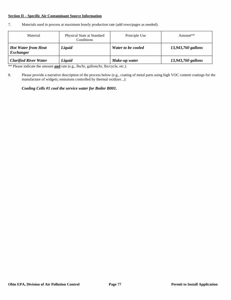
Section II – Specific Air Contaminant Source Information
Ohio EPA, Division of Air Pollution Control Page 77 Permit to Install Application
7. Materials used in process at maximum hourly production rate (add rows/pages as needed):
Material Physical State at Standard Conditions
Principle Use Amount**
Hot Water from Heat Exchanger
Liquid Water to be cooled 13,943,760 gallons
Clarified River Water Liquid Make-up water 13,943,760 gallons ** Please indicate the amount and rate (e.g., lbs/hr, gallons/hr, lbs/cycle, etc.). 8. Please provide a narrative description of the process below (e.g., coating of metal parts using high VOC content coatings for the
manufacture of widgets; emissions controlled by thermal oxidizer...): Cooling Cells #1 cool the service water for Boiler B001.
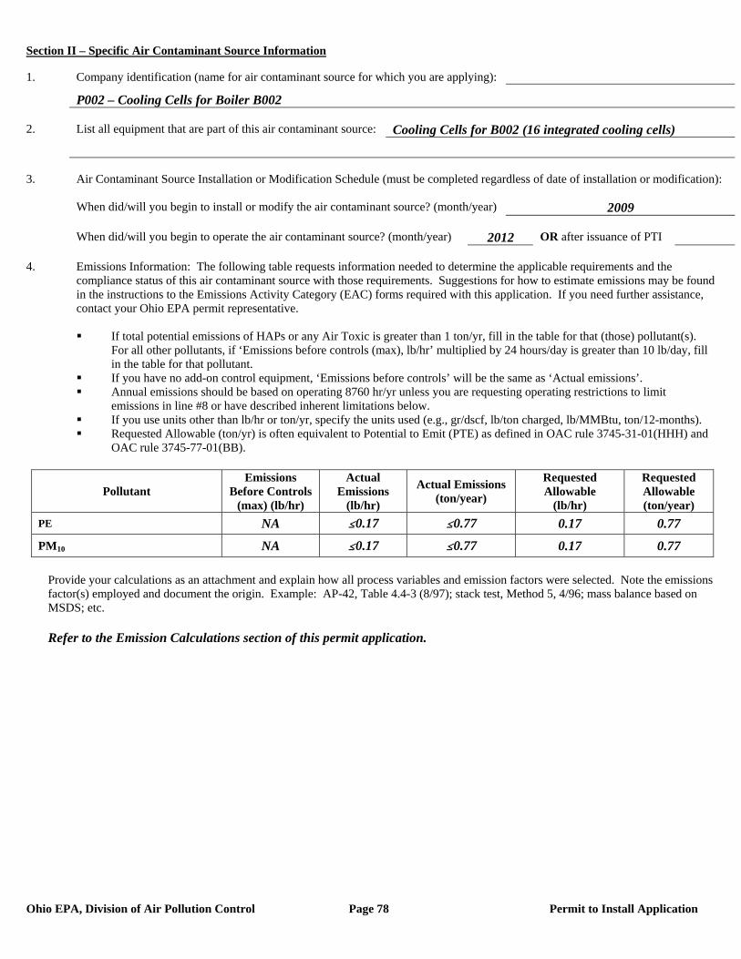
Section II – Specific Air Contaminant Source Information
Ohio EPA, Division of Air Pollution Control Page 78 Permit to Install Application
1. Company identification (name for air contaminant source for which you are applying):
P002 – Cooling Cells for Boiler B002 2. List all equipment that are part of this air contaminant source: Cooling Cells for B002 (16 integrated cooling cells) 3. Air Contaminant Source Installation or Modification Schedule (must be completed regardless of date of installation or modification): When did/will you begin to install or modify the air contaminant source? (month/year) 2009 When did/will you begin to operate the air contaminant source? (month/year) 2012 OR after issuance of PTI 4. Emissions Information: The following table requests information needed to determine the applicable requirements and the compliance status of this air contaminant source with those requirements. Suggestions for how to estimate emissions may be found in the instructions to the Emissions Activity Category (EAC) forms required with this application. If you need further assistance, contact your Ohio EPA permit representative.
If total potential emissions of HAPs or any Air Toxic is greater than 1 ton/yr, fill in the table for that (those) pollutant(s).
For all other pollutants, if ‘Emissions before controls (max), lb/hr’ multiplied by 24 hours/day is greater than 10 lb/day, fill in the table for that pollutant.
If you have no add-on control equipment, ‘Emissions before controls’ will be the same as ‘Actual emissions’. Annual emissions should be based on operating 8760 hr/yr unless you are requesting operating restrictions to limit
emissions in line #8 or have described inherent limitations below. If you use units other than lb/hr or ton/yr, specify the units used (e.g., gr/dscf, lb/ton charged, lb/MMBtu, ton/12-months). Requested Allowable (ton/yr) is often equivalent to Potential to Emit (PTE) as defined in OAC rule 3745-31-01(HHH) and
OAC rule 3745-77-01(BB).
Pollutant Emissions
Before Controls (max) (lb/hr)
Actual Emissions
(lb/hr)
Actual Emissions (ton/year)
Requested Allowable
(lb/hr)
Requested Allowable (ton/year)
PE NA #0.17 #0.77 0.17 0.77
PM10 NA #0.17 #0.77 0.17 0.77
Provide your calculations as an attachment and explain how all process variables and emission factors were selected. Note the emissions factor(s) employed and document the origin. Example: AP-42, Table 4.4-3 (8/97); stack test, Method 5, 4/96; mass balance based on MSDS; etc.
Refer to the Emission Calculations section of this permit application.

Section II – Specific Air Contaminant Source Information
Ohio EPA, Division of Air Pollution Control Page 79 Permit to Install Application
5. Does this air contaminant source employ emissions control equipment? Yes – fill out the applicable information below. No – proceed to item #6. Note: Pollutant abbreviations used below: Particulates = PE; Organic Compounds = OC; Sulfur Dioxide = SO2; Nitrogen Oxides = NOX; Carbon Monoxide = CO
Other, describe Mist Eliminator Manufacturer: Unknown Year installed: 2012 What do you call this control equipment: Mist Eliminator Pollutant(s) controlled: PE OC SO2 NOX CO Other Estimated capture efficiency (%) NA Basis for efficiency: NA Design control efficiency (%) NA Basis for efficiency: NA This is the only control equipment on this air contaminant source If no, this control equipment is: Primary Secondary Parallel List any other air contaminant sources that are also vented to this control equipment: None
6. Attach a Process or Activity Flow Diagram to this application for each air contaminant source included in this application. The
diagram should indicate their relationships to one another. See the line by line PTI instructions for additional information.
Cooling Cells for B002(P002)
Clarified River Water
Hot Water
Cooling Cells for B002(P002)
Flow Diagram
Steam Turbine CondenserCool Water
StackEmissions to Ambient Air
(P002-S1 through P002-S16)
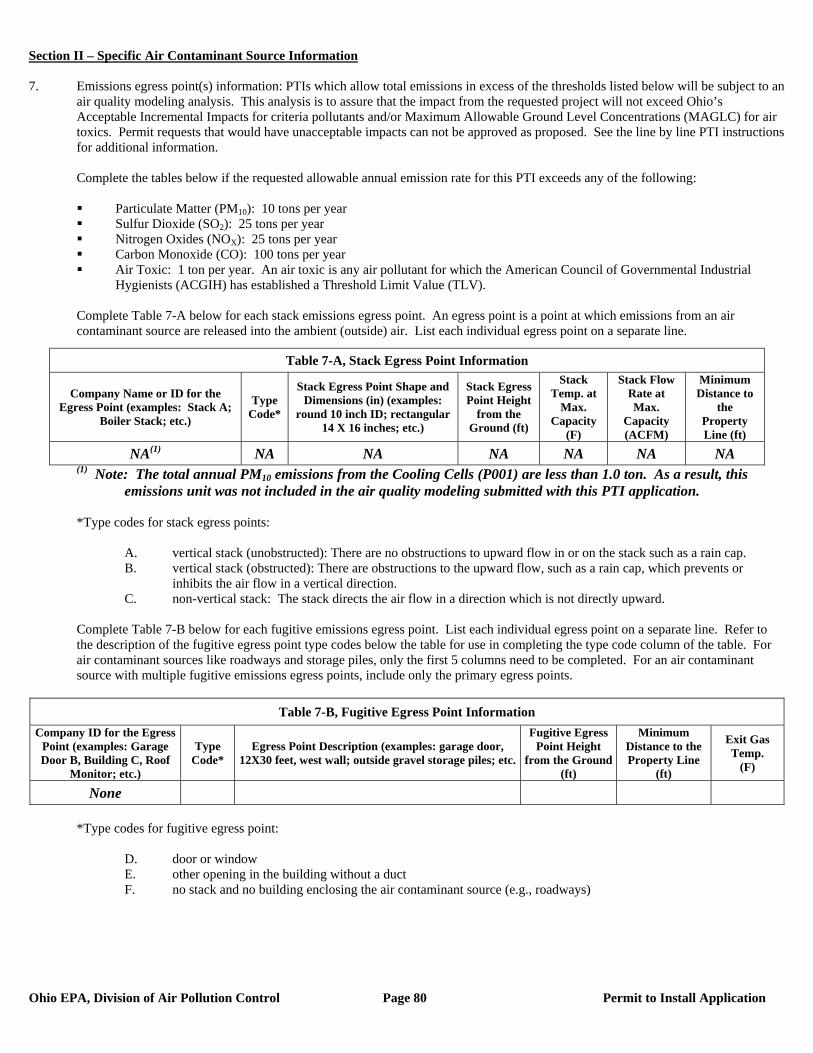
Section II – Specific Air Contaminant Source Information
Ohio EPA, Division of Air Pollution Control Page 80 Permit to Install Application
7. Emissions egress point(s) information: PTIs which allow total emissions in excess of the thresholds listed below will be subject to an
air quality modeling analysis. This analysis is to assure that the impact from the requested project will not exceed Ohio’s Acceptable Incremental Impacts for criteria pollutants and/or Maximum Allowable Ground Level Concentrations (MAGLC) for air toxics. Permit requests that would have unacceptable impacts can not be approved as proposed. See the line by line PTI instructions for additional information.
Complete the tables below if the requested allowable annual emission rate for this PTI exceeds any of the following:
Particulate Matter (PM10): 10 tons per year Sulfur Dioxide (SO2): 25 tons per year Nitrogen Oxides (NOX): 25 tons per year Carbon Monoxide (CO): 100 tons per year Air Toxic: 1 ton per year. An air toxic is any air pollutant for which the American Council of Governmental Industrial
Hygienists (ACGIH) has established a Threshold Limit Value (TLV).
Complete Table 7-A below for each stack emissions egress point. An egress point is a point at which emissions from an air contaminant source are released into the ambient (outside) air. List each individual egress point on a separate line.
(1) Note: The total annual PM10 emissions from the Cooling Cells (P001) are less than 1.0 ton. As a result, this emissions unit was not included in the air quality modeling submitted with this PTI application.
*Type codes for stack egress points:
A. vertical stack (unobstructed): There are no obstructions to upward flow in or on the stack such as a rain cap. B. vertical stack (obstructed): There are obstructions to the upward flow, such as a rain cap, which prevents or
inhibits the air flow in a vertical direction. C. non-vertical stack: The stack directs the air flow in a direction which is not directly upward.
Complete Table 7-B below for each fugitive emissions egress point. List each individual egress point on a separate line. Refer to the description of the fugitive egress point type codes below the table for use in completing the type code column of the table. For air contaminant sources like roadways and storage piles, only the first 5 columns need to be completed. For an air contaminant source with multiple fugitive emissions egress points, include only the primary egress points.
Table 7-B, Fugitive Egress Point Information
Company ID for the Egress Point (examples: Garage Door B, Building C, Roof
Monitor; etc.)
Type Code*
Egress Point Description (examples: garage door, 12X30 feet, west wall; outside gravel storage piles; etc.
Fugitive Egress Point Height
from the Ground (ft)
Minimum Distance to the Property Line
(ft)
Exit Gas Temp.
(F)
None
*Type codes for fugitive egress point:
D. door or window E. other opening in the building without a duct F. no stack and no building enclosing the air contaminant source (e.g., roadways)
Table 7-A, Stack Egress Point Information
Company Name or ID for the Egress Point (examples: Stack A;
Boiler Stack; etc.)
Type Code*
Stack Egress Point Shape and Dimensions (in) (examples:
round 10 inch ID; rectangular 14 X 16 inches; etc.)
Stack Egress Point Height
from the Ground (ft)
Stack Temp. at
Max. Capacity
(F)
Stack Flow Rate at Max.
Capacity (ACFM)
Minimum Distance to
the Property Line (ft)
NA(1) NA NA NA NA NA NA
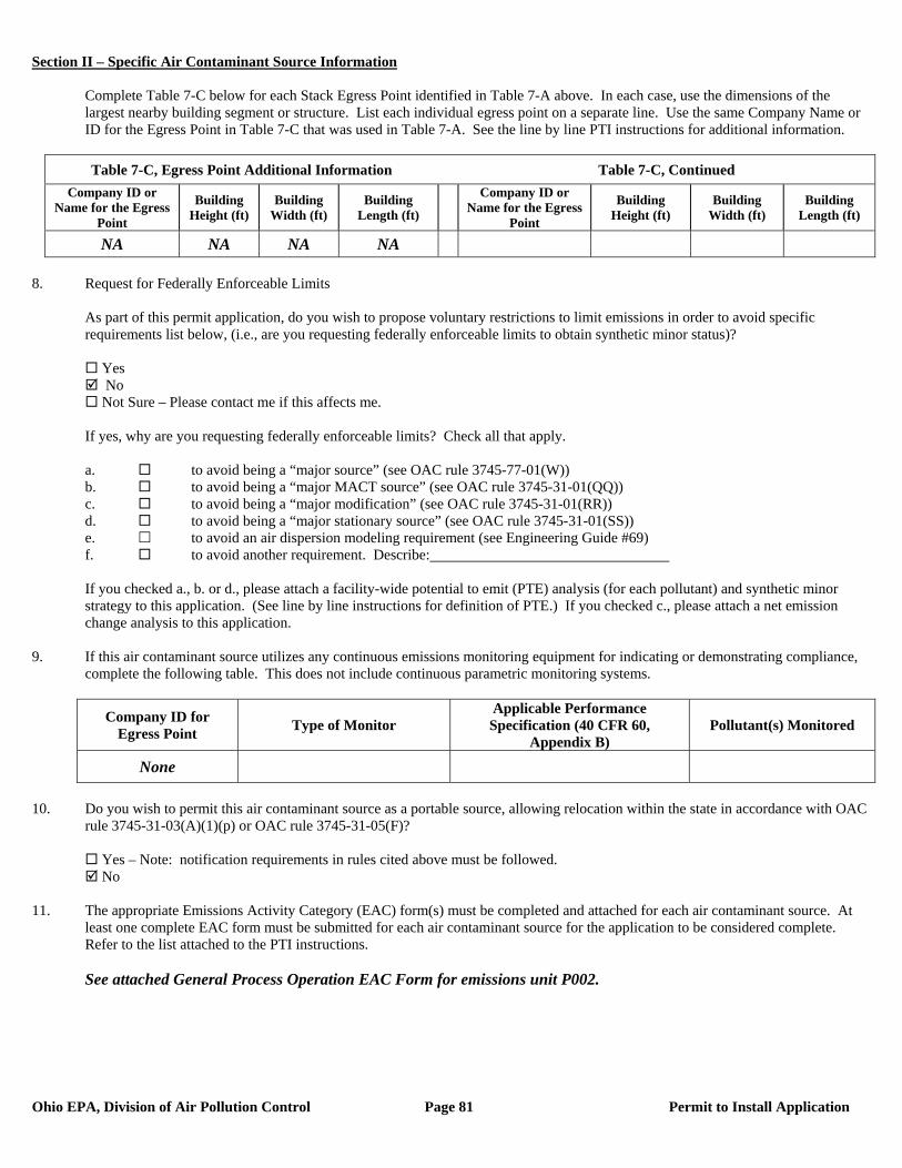
Section II – Specific Air Contaminant Source Information
Ohio EPA, Division of Air Pollution Control Page 81 Permit to Install Application
Complete Table 7-C below for each Stack Egress Point identified in Table 7-A above. In each case, use the dimensions of the largest nearby building segment or structure. List each individual egress point on a separate line. Use the same Company Name or ID for the Egress Point in Table 7-C that was used in Table 7-A. See the line by line PTI instructions for additional information.
Table 7-C, Egress Point Additional Information Table 7-C, Continued
Company ID or Name for the Egress
Point
Building Height (ft)
Building Width (ft)
Building Length (ft)
Company ID or Name for the Egress
Point
Building Height (ft)
Building Width (ft)
Building Length (ft)
NA NA NA NA 8. Request for Federally Enforceable Limits
As part of this permit application, do you wish to propose voluntary restrictions to limit emissions in order to avoid specific requirements list below, (i.e., are you requesting federally enforceable limits to obtain synthetic minor status)?
Yes No Not Sure – Please contact me if this affects me.
If yes, why are you requesting federally enforceable limits? Check all that apply. a. to avoid being a “major source” (see OAC rule 3745-77-01(W)) b. to avoid being a “major MACT source” (see OAC rule 3745-31-01(QQ)) c. to avoid being a “major modification” (see OAC rule 3745-31-01(RR)) d. to avoid being a “major stationary source” (see OAC rule 3745-31-01(SS)) e. to avoid an air dispersion modeling requirement (see Engineering Guide #69) f. to avoid another requirement. Describe: If you checked a., b. or d., please attach a facility-wide potential to emit (PTE) analysis (for each pollutant) and synthetic minor strategy to this application. (See line by line instructions for definition of PTE.) If you checked c., please attach a net emission change analysis to this application.
9. If this air contaminant source utilizes any continuous emissions monitoring equipment for indicating or demonstrating compliance, complete the following table. This does not include continuous parametric monitoring systems.
Company ID for Egress Point Type of Monitor
Applicable Performance Specification (40 CFR 60,
Appendix B) Pollutant(s) Monitored
None
10. Do you wish to permit this air contaminant source as a portable source, allowing relocation within the state in accordance with OAC
rule 3745-31-03(A)(1)(p) or OAC rule 3745-31-05(F)?
Yes – Note: notification requirements in rules cited above must be followed. No
11. The appropriate Emissions Activity Category (EAC) form(s) must be completed and attached for each air contaminant source. At
least one complete EAC form must be submitted for each air contaminant source for the application to be considered complete. Refer to the list attached to the PTI instructions. See attached General Process Operation EAC Form for emissions unit P002.
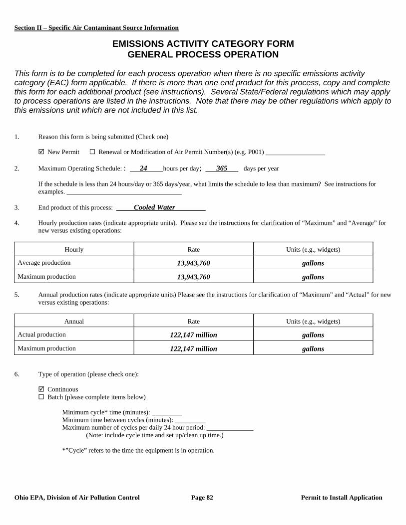
Section II – Specific Air Contaminant Source Information
Ohio EPA, Division of Air Pollution Control Page 82 Permit to Install Application
EMISSIONS ACTIVITY CATEGORY FORM GENERAL PROCESS OPERATION
This form is to be completed for each process operation when there is no specific emissions activity category (EAC) form applicable. If there is more than one end product for this process, copy and complete this form for each additional product (see instructions). Several State/Federal regulations which may apply to process operations are listed in the instructions. Note that there may be other regulations which apply to this emissions unit which are not included in this list. 1. Reason this form is being submitted (Check one) New Permit Renewal or Modification of Air Permit Number(s) (e.g. P001) 2. Maximum Operating Schedule: : 24 hours per day; 365 days per year
If the schedule is less than 24 hours/day or 365 days/year, what limits the schedule to less than maximum? See instructions for examples.
3. End product of this process: Cooled Water 4. Hourly production rates (indicate appropriate units). Please see the instructions for clarification of “Maximum” and “Average” for
new versus existing operations:
Hourly Rate Units (e.g., widgets)
Average production 13,943,760 gallons
Maximum production 13,943,760 gallons 5. Annual production rates (indicate appropriate units) Please see the instructions for clarification of “Maximum” and “Actual” for new
versus existing operations:
Annual Rate Units (e.g., widgets)
Actual production 122,147 million gallons
Maximum production 122,147 million gallons 6. Type of operation (please check one):
Continuous Batch (please complete items below)
Minimum cycle* time (minutes): Minimum time between cycles (minutes): Maximum number of cycles per daily 24 hour period:
(Note: include cycle time and set up/clean up time.) *”Cycle” refers to the time the equipment is in operation.

Section II – Specific Air Contaminant Source Information
Ohio EPA, Division of Air Pollution Control Page 83 Permit to Install Application
7. Materials used in process at maximum hourly production rate (add rows/pages as needed):
Material Physical State at Standard Conditions
Principle Use Amount**
Hot Water from Heat Exchanger
Liquid Water to be cooled 13,943,760 gallons
Clarified River Water Liquid Make-up water 13,943,760 gallons ** Please indicate the amount and rate (e.g., lbs/hr, gallons/hr, lbs/cycle, etc.). 8. Please provide a narrative description of the process below (e.g., coating of metal parts using high VOC content coatings for the
manufacture of widgets; emissions controlled by thermal oxidizer...): Cooling Cells #2 cool the service water for Boiler B002.
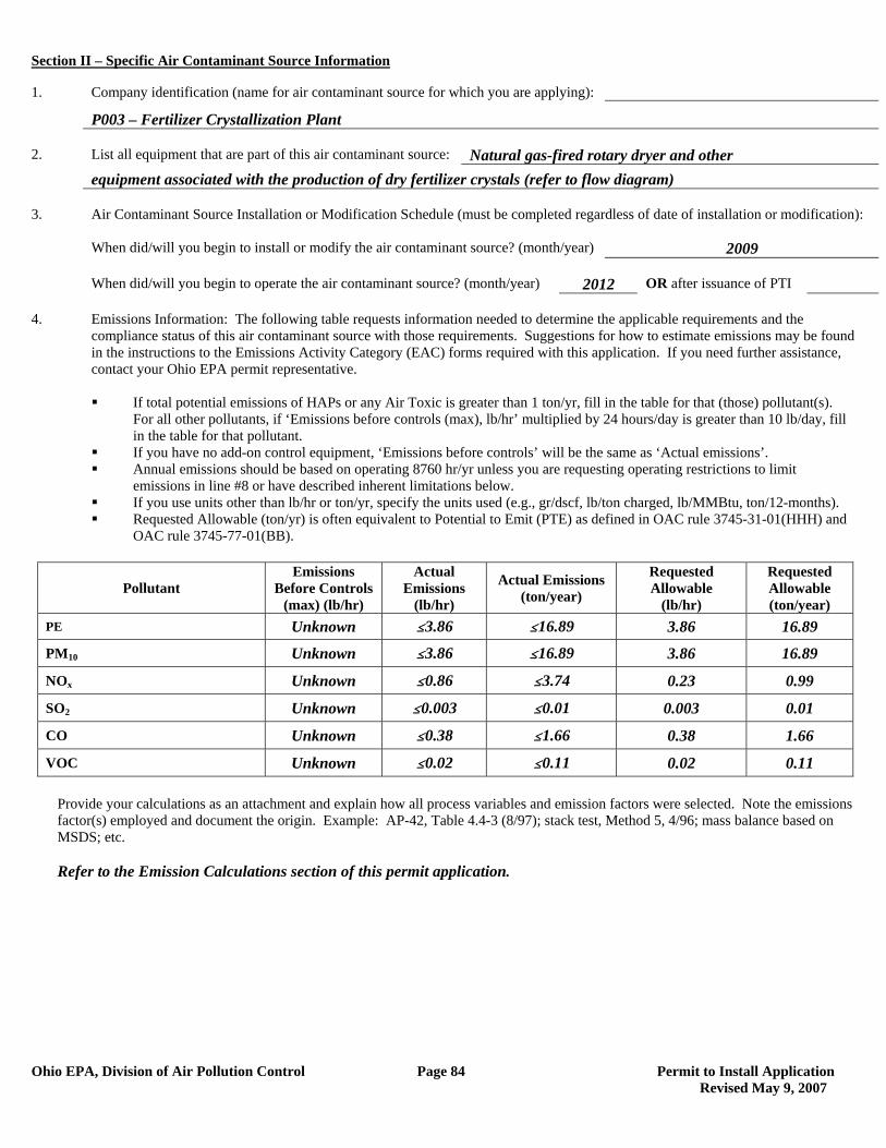
Section II – Specific Air Contaminant Source Information
Ohio EPA, Division of Air Pollution Control Page 84 Permit to Install Application Revised May 9, 2007
1. Company identification (name for air contaminant source for which you are applying):
P003 – Fertilizer Crystallization Plant 2. List all equipment that are part of this air contaminant source: Natural gas-fired rotary dryer and other equipment associated with the production of dry fertilizer crystals (refer to flow diagram) 3. Air Contaminant Source Installation or Modification Schedule (must be completed regardless of date of installation or modification): When did/will you begin to install or modify the air contaminant source? (month/year) 2009 When did/will you begin to operate the air contaminant source? (month/year) 2012 OR after issuance of PTI 4. Emissions Information: The following table requests information needed to determine the applicable requirements and the compliance status of this air contaminant source with those requirements. Suggestions for how to estimate emissions may be found in the instructions to the Emissions Activity Category (EAC) forms required with this application. If you need further assistance, contact your Ohio EPA permit representative.
If total potential emissions of HAPs or any Air Toxic is greater than 1 ton/yr, fill in the table for that (those) pollutant(s).
For all other pollutants, if ‘Emissions before controls (max), lb/hr’ multiplied by 24 hours/day is greater than 10 lb/day, fill in the table for that pollutant.
If you have no add-on control equipment, ‘Emissions before controls’ will be the same as ‘Actual emissions’. Annual emissions should be based on operating 8760 hr/yr unless you are requesting operating restrictions to limit
emissions in line #8 or have described inherent limitations below. If you use units other than lb/hr or ton/yr, specify the units used (e.g., gr/dscf, lb/ton charged, lb/MMBtu, ton/12-months). Requested Allowable (ton/yr) is often equivalent to Potential to Emit (PTE) as defined in OAC rule 3745-31-01(HHH) and
OAC rule 3745-77-01(BB).
Pollutant Emissions
Before Controls (max) (lb/hr)
Actual Emissions
(lb/hr)
Actual Emissions (ton/year)
Requested Allowable
(lb/hr)
Requested Allowable (ton/year)
PE Unknown #3.86 #16.89 3.86 16.89
PM10 Unknown #3.86 #16.89 3.86 16.89
NOx Unknown #0.86 #3.74 0.23 0.99
SO2 Unknown #0.003 #0.01 0.003 0.01
CO Unknown #0.38 #1.66 0.38 1.66
VOC Unknown #0.02 #0.11 0.02 0.11
Provide your calculations as an attachment and explain how all process variables and emission factors were selected. Note the emissions factor(s) employed and document the origin. Example: AP-42, Table 4.4-3 (8/97); stack test, Method 5, 4/96; mass balance based on MSDS; etc.
Refer to the Emission Calculations section of this permit application.
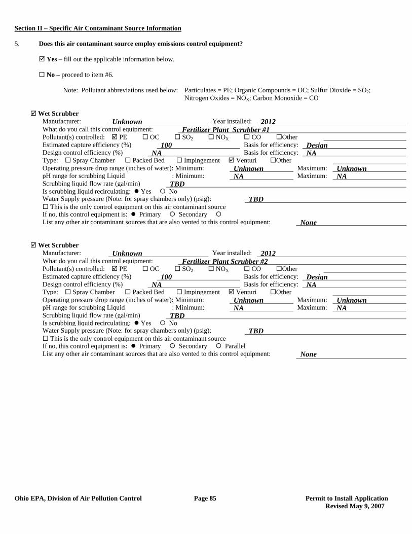
Section II – Specific Air Contaminant Source Information
Ohio EPA, Division of Air Pollution Control Page 85 Permit to Install Application Revised May 9, 2007
5. Does this air contaminant source employ emissions control equipment? Yes – fill out the applicable information below. No – proceed to item #6. Note: Pollutant abbreviations used below: Particulates = PE; Organic Compounds = OC; Sulfur Dioxide = SO2; Nitrogen Oxides = NOX; Carbon Monoxide = CO
Wet Scrubber Manufacturer: Unknown Year installed: 2012 What do you call this control equipment: Fertilizer Plant Scrubber #1 Pollutant(s) controlled: PE OC SO2 NOX CO Other Estimated capture efficiency (%) 100 Basis for efficiency: Design Design control efficiency (%) NA Basis for efficiency: NA Type: Spray Chamber Packed Bed Impingement Venturi Other Operating pressure drop range (inches of water): Minimum: Unknown Maximum: Unknown pH range for scrubbing Liquid : Minimum: NA Maximum: NA Scrubbing liquid flow rate (gal/min) TBD Is scrubbing liquid recirculating: Yes No Water Supply pressure (Note: for spray chambers only) (psig): TBD This is the only control equipment on this air contaminant source If no, this control equipment is: Primary Secondary List any other air contaminant sources that are also vented to this control equipment: None
Wet Scrubber Manufacturer: Unknown Year installed: 2012 What do you call this control equipment: Fertilizer Plant Scrubber #2 Pollutant(s) controlled: PE OC SO2 NOX CO Other Estimated capture efficiency (%) 100 Basis for efficiency: Design Design control efficiency (%) NA Basis for efficiency: NA Type: Spray Chamber Packed Bed Impingement Venturi Other Operating pressure drop range (inches of water): Minimum: Unknown Maximum: Unknown pH range for scrubbing Liquid : Minimum: NA Maximum: NA Scrubbing liquid flow rate (gal/min) TBD Is scrubbing liquid recirculating: Yes No Water Supply pressure (Note: for spray chambers only) (psig): TBD This is the only control equipment on this air contaminant source If no, this control equipment is: Primary Secondary Parallel List any other air contaminant sources that are also vented to this control equipment: None
Section II – Specific Air Contaminant Source Information
Ohio EPA, Division of Air Pollution Control Page 86 Permit to Install Application Revised May 9, 2007
6. Attach a Process or Activity Flow Diagram to this application for each air contaminant source included in this application. The
diagram should indicate their relationships to one another. See the line by line PTI instructions for additional information. A Process Flow Diagram is on the following page.
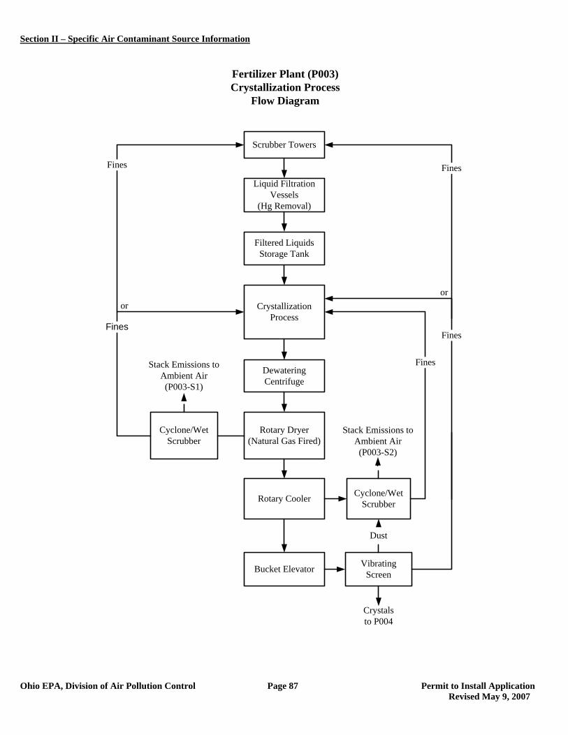
Section II – Specific Air Contaminant Source Information
Ohio EPA, Division of Air Pollution Control Page 87 Permit to Install Application Revised May 9, 2007
oror
Scrubber Towers
Liquid Filtration Vessels
(Hg Removal)
Filtered LiquidsStorage Tank
CrystallizationProcess
DewateringCentrifuge
Rotary Dryer(Natural Gas Fired)
Rotary Cooler
Bucket Elevator Vibrating Screen
Cyclone/Wet Scrubber
Fertilizer Plant (P003)Crystallization Process
Flow Diagram
Cyclone/Wet Scrubber
Fines
Stack Emissions to Ambient Air(P003-S2)
Stack Emissions to Ambient Air(P003-S1)
Crystals to P004
Fines
Fines
Dust
FinesFines
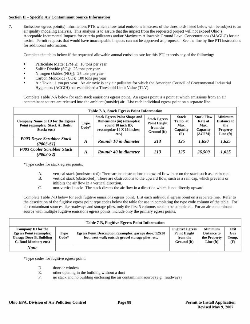
Section II – Specific Air Contaminant Source Information
Ohio EPA, Division of Air Pollution Control Page 88 Permit to Install Application Revised May 9, 2007
7. Emissions egress point(s) information: PTIs which allow total emissions in excess of the thresholds listed below will be subject to an
air quality modeling analysis. This analysis is to assure that the impact from the requested project will not exceed Ohio’s Acceptable Incremental Impacts for criteria pollutants and/or Maximum Allowable Ground Level Concentrations (MAGLC) for air toxics. Permit requests that would have unacceptable impacts can not be approved as proposed. See the line by line PTI instructions for additional information.
Complete the tables below if the requested allowable annual emission rate for this PTI exceeds any of the following:
Particulate Matter (PM10): 10 tons per year Sulfur Dioxide (SO2): 25 tons per year Nitrogen Oxides (NOX): 25 tons per year Carbon Monoxide (CO): 100 tons per year Air Toxic: 1 ton per year. An air toxic is any air pollutant for which the American Council of Governmental Industrial
Hygienists (ACGIH) has established a Threshold Limit Value (TLV).
Complete Table 7-A below for each stack emissions egress point. An egress point is a point at which emissions from an air contaminant source are released into the ambient (outside) air. List each individual egress point on a separate line.
*Type codes for stack egress points:
A. vertical stack (unobstructed): There are no obstructions to upward flow in or on the stack such as a rain cap. B. vertical stack (obstructed): There are obstructions to the upward flow, such as a rain cap, which prevents or
inhibits the air flow in a vertical direction. C. non-vertical stack: The stack directs the air flow in a direction which is not directly upward.
Complete Table 7-B below for each fugitive emissions egress point. List each individual egress point on a separate line. Refer to the description of the fugitive egress point type codes below the table for use in completing the type code column of the table. For air contaminant sources like roadways and storage piles, only the first 5 columns need to be completed. For an air contaminant source with multiple fugitive emissions egress points, include only the primary egress points.
Table 7-B, Fugitive Egress Point Information
Company ID for the Egress Point (examples: Garage Door B, Building
C, Roof Monitor; etc.)
Type Code*
Egress Point Description (examples: garage door, 12X30 feet, west wall; outside gravel storage piles; etc.
Fugitive Egress Point Height
from the Ground (ft)
Minimum Distance to
the Property Line (ft)
Exit Gas
Temp. (F)
None
*Type codes for fugitive egress point:
D. door or window E. other opening in the building without a duct F. no stack and no building enclosing the air contaminant source (e.g., roadways)
Table 7-A, Stack Egress Point Information
Company Name or ID for the Egress Point (examples: Stack A; Boiler
Stack; etc.)
Type Code*
Stack Egress Point Shape and Dimensions (in) (examples:
round 10 inch ID; rectangular 14 X 16 inches;
etc.)
Stack Egress Point Height
from the Ground (ft)
Stack Temp. at
Max. Capacity
(F)
Stack Flow Rate at Max.
Capacity (ACFM)
Minimum Distance to
the Property Line (ft)
P003 Dryer Scrubber Stack (P003-S1) A Round: 10 in diameter 213 125 1,650 1,625
P003 Cooler Scrubber Stack (P003-S2) A Round: 40 in diameter 213 125 26,500 1,625
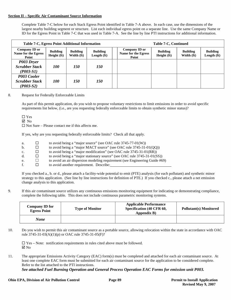
Section II – Specific Air Contaminant Source Information
Ohio EPA, Division of Air Pollution Control Page 89 Permit to Install Application Revised May 9, 2007
Complete Table 7-C below for each Stack Egress Point identified in Table 7-A above. In each case, use the dimensions of the largest nearby building segment or structure. List each individual egress point on a separate line. Use the same Company Name or ID for the Egress Point in Table 7-C that was used in Table 7-A. See the line by line PTI instructions for additional information.
Table 7-C, Egress Point Additional Information Table 7-C, Continued
Company ID or Name for the Egress
Point
Building Height (ft)
Building Width (ft)
Building Length (ft)
Company ID or Name for the Egress
Point
Building Height (ft)
Building Width (ft)
Building Length (ft)
P003 Dryer Scrubber Stack
(P003-S1) 100 150 150
P003 Cooler Scrubber Stack
(P003-S2) 100 150 150
8. Request for Federally Enforceable Limits
As part of this permit application, do you wish to propose voluntary restrictions to limit emissions in order to avoid specific requirements list below, (i.e., are you requesting federally enforceable limits to obtain synthetic minor status)?
Yes No Not Sure – Please contact me if this affects me.
If yes, why are you requesting federally enforceable limits? Check all that apply. a. to avoid being a “major source” (see OAC rule 3745-77-01(W)) b. to avoid being a “major MACT source” (see OAC rule 3745-31-01(QQ)) c. to avoid being a “major modification” (see OAC rule 3745-31-01(RR)) d. to avoid being a “major stationary source” (see OAC rule 3745-31-01(SS)) e. to avoid an air dispersion modeling requirement (see Engineering Guide #69) f. to avoid another requirement. Describe: If you checked a., b. or d., please attach a facility-wide potential to emit (PTE) analysis (for each pollutant) and synthetic minor strategy to this application. (See line by line instructions for definition of PTE.) If you checked c., please attach a net emission change analysis to this application.
9. If this air contaminant source utilizes any continuous emissions monitoring equipment for indicating or demonstrating compliance, complete the following table. This does not include continuous parametric monitoring systems.
Company ID for Egress Point Type of Monitor
Applicable Performance Specification (40 CFR 60,
Appendix B) Pollutant(s) Monitored
None
10. Do you wish to permit this air contaminant source as a portable source, allowing relocation within the state in accordance with OAC
rule 3745-31-03(A)(1)(p) or OAC rule 3745-31-05(F)?
Yes – Note: notification requirements in rules cited above must be followed. No
11. The appropriate Emissions Activity Category (EAC) form(s) must be completed and attached for each air contaminant source. At
least one complete EAC form must be submitted for each air contaminant source for the application to be considered complete. Refer to the list attached to the PTI instructions. See attached Fuel Burning Operation and General Process Operation EAC Forms for emission unit P003.
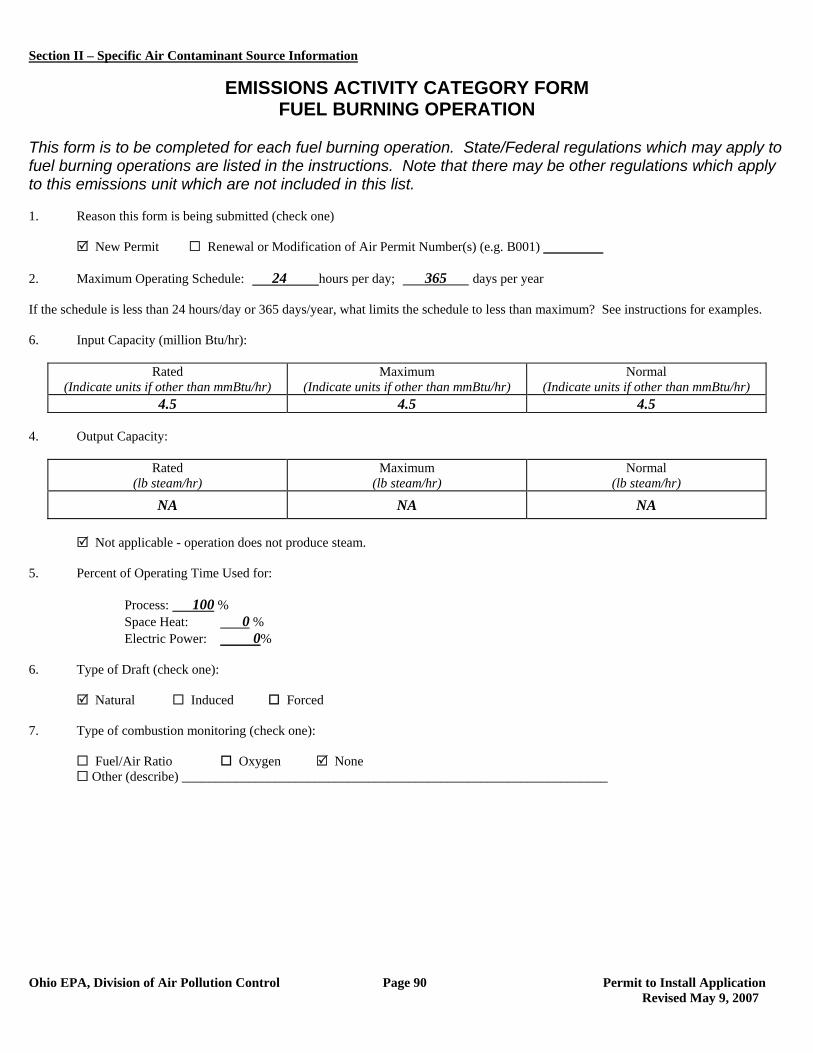
Section II – Specific Air Contaminant Source Information
Ohio EPA, Division of Air Pollution Control Page 90 Permit to Install Application Revised May 9, 2007
EMISSIONS ACTIVITY CATEGORY FORM
FUEL BURNING OPERATION This form is to be completed for each fuel burning operation. State/Federal regulations which may apply to fuel burning operations are listed in the instructions. Note that there may be other regulations which apply to this emissions unit which are not included in this list. 1. Reason this form is being submitted (check one)
New Permit Renewal or Modification of Air Permit Number(s) (e.g. B001) 2. Maximum Operating Schedule: 24 hours per day; 365 days per year If the schedule is less than 24 hours/day or 365 days/year, what limits the schedule to less than maximum? See instructions for examples. 6. Input Capacity (million Btu/hr):
Rated (Indicate units if other than mmBtu/hr)
Maximum (Indicate units if other than mmBtu/hr)
Normal (Indicate units if other than mmBtu/hr)
4.5 4.5 4.5 4. Output Capacity:
Rated (lb steam/hr)
Maximum (lb steam/hr)
Normal (lb steam/hr)
NA NA NA
Not applicable - operation does not produce steam. 5. Percent of Operating Time Used for: Process: 100 %
Space Heat: 0 % Electric Power: 0%
6. Type of Draft (check one):
Natural Induced Forced 7. Type of combustion monitoring (check one):
Fuel/Air Ratio Oxygen None Other (describe) ________________________________________________________________
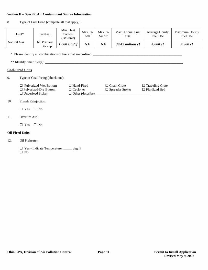
Section II – Specific Air Contaminant Source Information
Ohio EPA, Division of Air Pollution Control Page 91 Permit to Install Application Revised May 9, 2007
8. Type of Fuel Fired (complete all that apply):
Fuel* Fired as... Min. Heat Content
(Btu/unit)
Max. % Ash
Max. % Sulfur
Max. Annual Fuel Use
Average Hourly Fuel Use
Maximum Hourly Fuel Use
Natural Gas Primary � Backup 1,000 Btu/cf NA NA 39.42 million cf 4,000 cf 4,500 cf
* Please identify all combinations of fuels that are co-fired: ____________________________________________________ ** Identify other fuel(s): _________________________________________________________________________________ Coal-Fired Units 9. Type of Coal Firing (check one):
Pulverized-Wet Bottom Hand-Fired Chain Grate Traveling Grate Pulverized-Dry Bottom Cyclones Spreader Stoker Fluidized Bed Underfeed Stoker Other (describe) ________________________________
10. Flyash Reinjection:
Yes No 11. Overfire Air:
Yes No Oil-Fired Units 12. Oil Preheater:
Yes - Indicate Temperature: _____ deg. F No
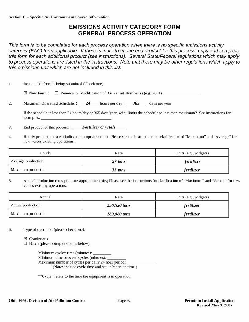
Section II – Specific Air Contaminant Source Information
Ohio EPA, Division of Air Pollution Control Page 92 Permit to Install Application Revised May 9, 2007
EMISSIONS ACTIVITY CATEGORY FORM GENERAL PROCESS OPERATION
This form is to be completed for each process operation when there is no specific emissions activity category (EAC) form applicable. If there is more than one end product for this process, copy and complete this form for each additional product (see instructions). Several State/Federal regulations which may apply to process operations are listed in the instructions. Note that there may be other regulations which apply to this emissions unit which are not included in this list. 1. Reason this form is being submitted (Check one) New Permit Renewal or Modification of Air Permit Number(s) (e.g. P001) 2. Maximum Operating Schedule: : 24 hours per day; 365 days per year
If the schedule is less than 24 hours/day or 365 days/year, what limits the schedule to less than maximum? See instructions for examples.
3. End product of this process: Fertilizer Crystals 4. Hourly production rates (indicate appropriate units). Please see the instructions for clarification of “Maximum” and “Average” for
new versus existing operations:
Hourly Rate Units (e.g., widgets)
Average production 27 tons fertilizer
Maximum production 33 tons fertilizer 5. Annual production rates (indicate appropriate units) Please see the instructions for clarification of “Maximum” and “Actual” for new
versus existing operations:
Annual Rate Units (e.g., widgets)
Actual production 236,520 tons fertilizer
Maximum production 289,080 tons fertilizer 6. Type of operation (please check one):
Continuous Batch (please complete items below)
Minimum cycle* time (minutes): Minimum time between cycles (minutes): Maximum number of cycles per daily 24 hour period:
(Note: include cycle time and set up/clean up time.) *”Cycle” refers to the time the equipment is in operation.
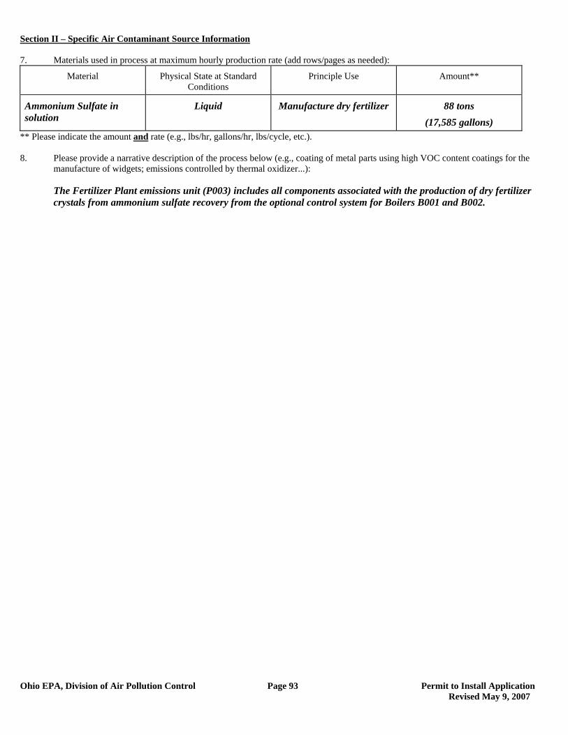
Section II – Specific Air Contaminant Source Information
Ohio EPA, Division of Air Pollution Control Page 93 Permit to Install Application Revised May 9, 2007
7. Materials used in process at maximum hourly production rate (add rows/pages as needed):
Material Physical State at Standard Conditions
Principle Use Amount**
Ammonium Sulfate in solution
Liquid Manufacture dry fertilizer 88 tons (17,585 gallons)
** Please indicate the amount and rate (e.g., lbs/hr, gallons/hr, lbs/cycle, etc.). 8. Please provide a narrative description of the process below (e.g., coating of metal parts using high VOC content coatings for the
manufacture of widgets; emissions controlled by thermal oxidizer...): The Fertilizer Plant emissions unit (P003) includes all components associated with the production of dry fertilizer
crystals from ammonium sulfate recovery from the optional control system for Boilers B001 and B002.
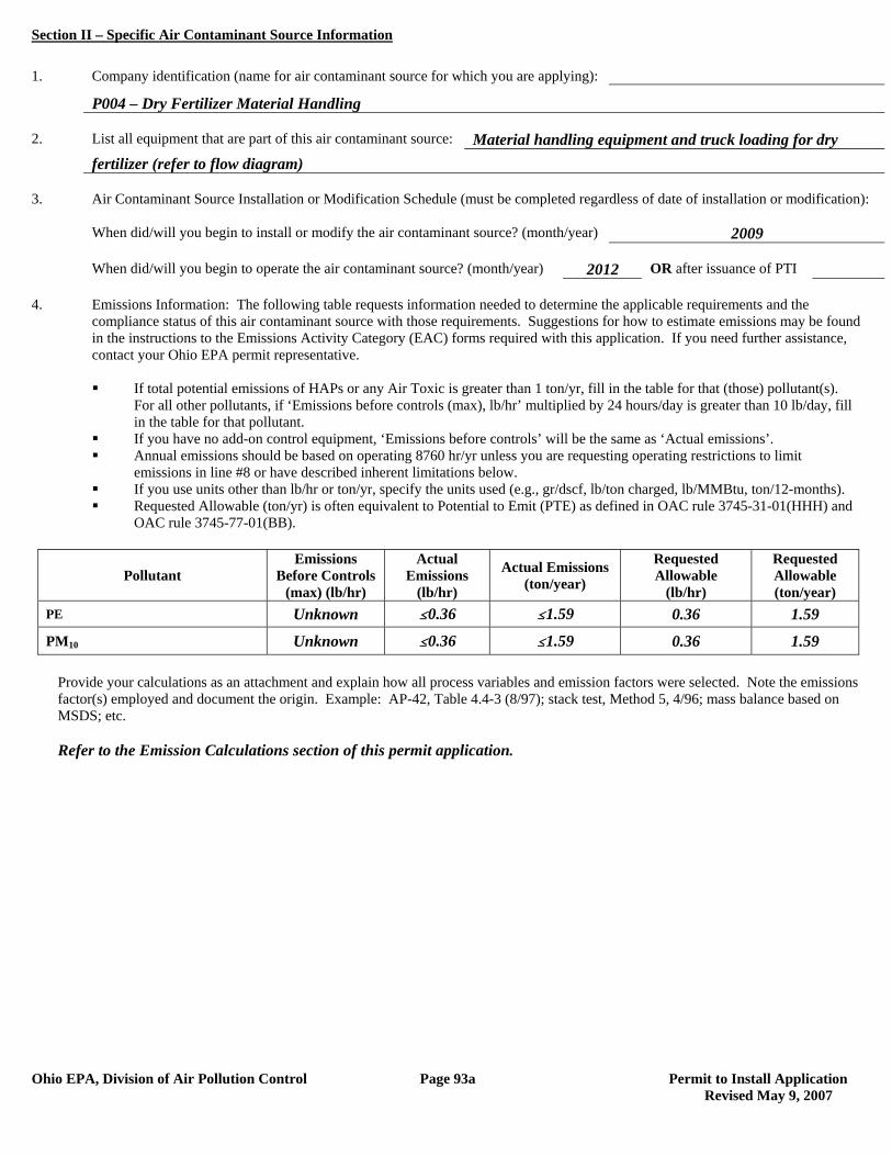
Section II – Specific Air Contaminant Source Information
Ohio EPA, Division of Air Pollution Control Page 93a Permit to Install Application Revised May 9, 2007
1. Company identification (name for air contaminant source for which you are applying):
P004 – Dry Fertilizer Material Handling 2. List all equipment that are part of this air contaminant source: Material handling equipment and truck loading for dry fertilizer (refer to flow diagram) 3. Air Contaminant Source Installation or Modification Schedule (must be completed regardless of date of installation or modification): When did/will you begin to install or modify the air contaminant source? (month/year) 2009 When did/will you begin to operate the air contaminant source? (month/year) 2012 OR after issuance of PTI 4. Emissions Information: The following table requests information needed to determine the applicable requirements and the compliance status of this air contaminant source with those requirements. Suggestions for how to estimate emissions may be found in the instructions to the Emissions Activity Category (EAC) forms required with this application. If you need further assistance, contact your Ohio EPA permit representative.
If total potential emissions of HAPs or any Air Toxic is greater than 1 ton/yr, fill in the table for that (those) pollutant(s).
For all other pollutants, if ‘Emissions before controls (max), lb/hr’ multiplied by 24 hours/day is greater than 10 lb/day, fill in the table for that pollutant.
If you have no add-on control equipment, ‘Emissions before controls’ will be the same as ‘Actual emissions’. Annual emissions should be based on operating 8760 hr/yr unless you are requesting operating restrictions to limit
emissions in line #8 or have described inherent limitations below. If you use units other than lb/hr or ton/yr, specify the units used (e.g., gr/dscf, lb/ton charged, lb/MMBtu, ton/12-months). Requested Allowable (ton/yr) is often equivalent to Potential to Emit (PTE) as defined in OAC rule 3745-31-01(HHH) and
OAC rule 3745-77-01(BB).
Pollutant Emissions
Before Controls (max) (lb/hr)
Actual Emissions
(lb/hr)
Actual Emissions (ton/year)
Requested Allowable
(lb/hr)
Requested Allowable (ton/year)
PE Unknown #0.36 #1.59 0.36 1.59
PM10 Unknown #0.36 #1.59 0.36 1.59
Provide your calculations as an attachment and explain how all process variables and emission factors were selected. Note the emissions factor(s) employed and document the origin. Example: AP-42, Table 4.4-3 (8/97); stack test, Method 5, 4/96; mass balance based on MSDS; etc.
Refer to the Emission Calculations section of this permit application.
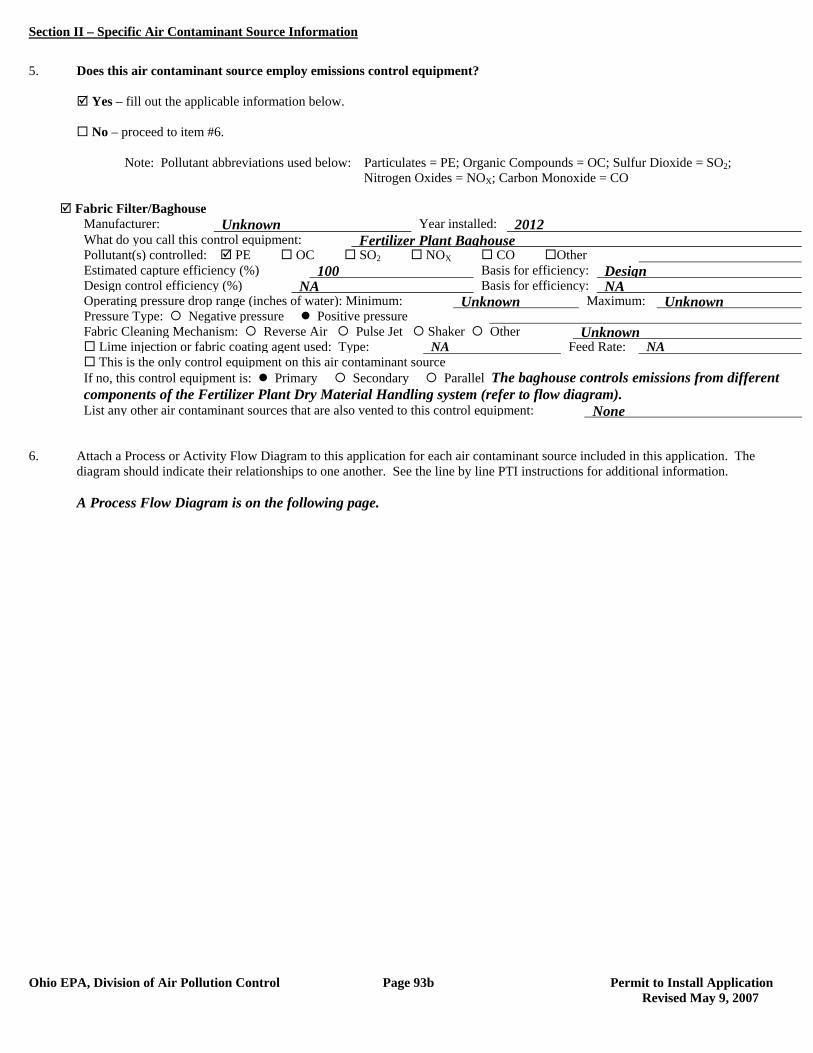
Section II – Specific Air Contaminant Source Information
Ohio EPA, Division of Air Pollution Control Page 93b Permit to Install Application Revised May 9, 2007
5. Does this air contaminant source employ emissions control equipment? Yes – fill out the applicable information below. No – proceed to item #6. Note: Pollutant abbreviations used below: Particulates = PE; Organic Compounds = OC; Sulfur Dioxide = SO2; Nitrogen Oxides = NOX; Carbon Monoxide = CO
Fabric Filter/Baghouse Manufacturer: Unknown Year installed: 2012 What do you call this control equipment: Fertilizer Plant Baghouse Pollutant(s) controlled: PE OC SO2 NOX CO Other Estimated capture efficiency (%) 100 Basis for efficiency: Design Design control efficiency (%) NA Basis for efficiency: NA Operating pressure drop range (inches of water): Minimum: Unknown Maximum: Unknown Pressure Type: Negative pressure Positive pressure Fabric Cleaning Mechanism: Reverse Air Pulse Jet Shaker Other Unknown Lime injection or fabric coating agent used: Type: NA Feed Rate: NA This is the only control equipment on this air contaminant source If no, this control equipment is: Primary Secondary Parallel The baghouse controls emissions from different
components of the Fertilizer Plant Dry Material Handling system (refer to flow diagram). List any other air contaminant sources that are also vented to this control equipment: None
6. Attach a Process or Activity Flow Diagram to this application for each air contaminant source included in this application. The
diagram should indicate their relationships to one another. See the line by line PTI instructions for additional information. A Process Flow Diagram is on the following page.
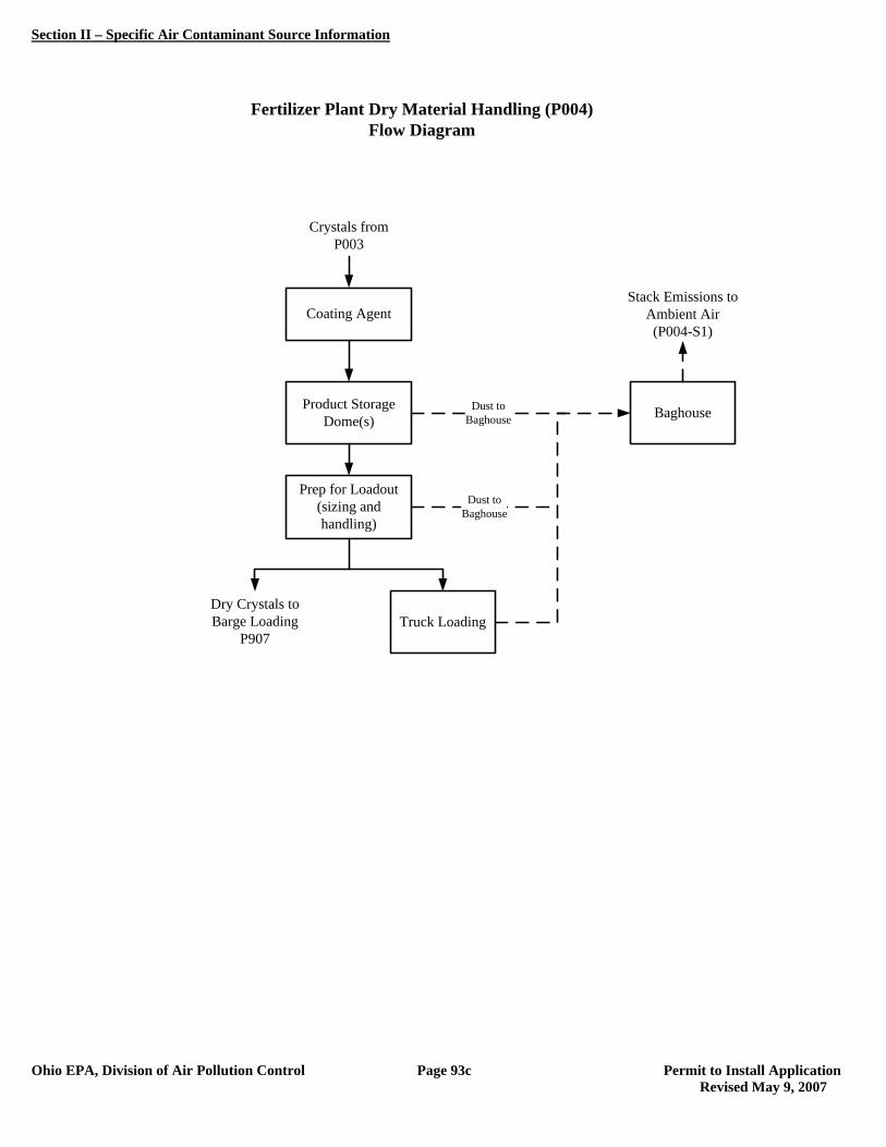
Section II – Specific Air Contaminant Source Information
Ohio EPA, Division of Air Pollution Control Page 93c Permit to Install Application Revised May 9, 2007
Fertilizer Plant Dry Material Handling (P004)Flow Diagram
Crystals from P003
Coating Agent
Product StorageDome(s)
Prep for Loadout(sizing and handling)
Truck Loading
BaghouseDust toBaghouse
Stack Emissions to Ambient Air(P004-S1)
Dust toBaghouse
Dry Crystals to Barge Loading
P907
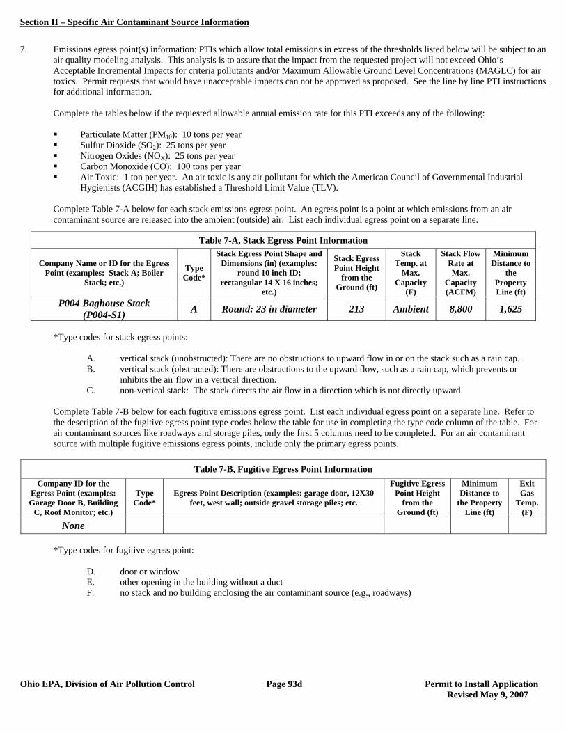
Section II – Specific Air Contaminant Source Information
Ohio EPA, Division of Air Pollution Control Page 93d Permit to Install Application Revised May 9, 2007
7. Emissions egress point(s) information: PTIs which allow total emissions in excess of the thresholds listed below will be subject to an
air quality modeling analysis. This analysis is to assure that the impact from the requested project will not exceed Ohio’s Acceptable Incremental Impacts for criteria pollutants and/or Maximum Allowable Ground Level Concentrations (MAGLC) for air toxics. Permit requests that would have unacceptable impacts can not be approved as proposed. See the line by line PTI instructions for additional information.
Complete the tables below if the requested allowable annual emission rate for this PTI exceeds any of the following:
Particulate Matter (PM10): 10 tons per year Sulfur Dioxide (SO2): 25 tons per year Nitrogen Oxides (NOX): 25 tons per year Carbon Monoxide (CO): 100 tons per year Air Toxic: 1 ton per year. An air toxic is any air pollutant for which the American Council of Governmental Industrial
Hygienists (ACGIH) has established a Threshold Limit Value (TLV).
Complete Table 7-A below for each stack emissions egress point. An egress point is a point at which emissions from an air contaminant source are released into the ambient (outside) air. List each individual egress point on a separate line.
*Type codes for stack egress points:
A. vertical stack (unobstructed): There are no obstructions to upward flow in or on the stack such as a rain cap. B. vertical stack (obstructed): There are obstructions to the upward flow, such as a rain cap, which prevents or
inhibits the air flow in a vertical direction. C. non-vertical stack: The stack directs the air flow in a direction which is not directly upward.
Complete Table 7-B below for each fugitive emissions egress point. List each individual egress point on a separate line. Refer to the description of the fugitive egress point type codes below the table for use in completing the type code column of the table. For air contaminant sources like roadways and storage piles, only the first 5 columns need to be completed. For an air contaminant source with multiple fugitive emissions egress points, include only the primary egress points.
Table 7-B, Fugitive Egress Point Information
Company ID for the Egress Point (examples: Garage Door B, Building
C, Roof Monitor; etc.)
Type Code*
Egress Point Description (examples: garage door, 12X30 feet, west wall; outside gravel storage piles; etc.
Fugitive Egress Point Height
from the Ground (ft)
Minimum Distance to
the Property Line (ft)
Exit Gas
Temp. (F)
None
*Type codes for fugitive egress point:
D. door or window E. other opening in the building without a duct F. no stack and no building enclosing the air contaminant source (e.g., roadways)
Table 7-A, Stack Egress Point Information
Company Name or ID for the Egress Point (examples: Stack A; Boiler
Stack; etc.)
Type Code*
Stack Egress Point Shape and Dimensions (in) (examples:
round 10 inch ID; rectangular 14 X 16 inches;
etc.)
Stack Egress Point Height
from the Ground (ft)
Stack Temp. at
Max. Capacity
(F)
Stack Flow Rate at Max.
Capacity (ACFM)
Minimum Distance to
the Property Line (ft)
P004 Baghouse Stack (P004-S1) A Round: 23 in diameter 213 Ambient 8,800 1,625
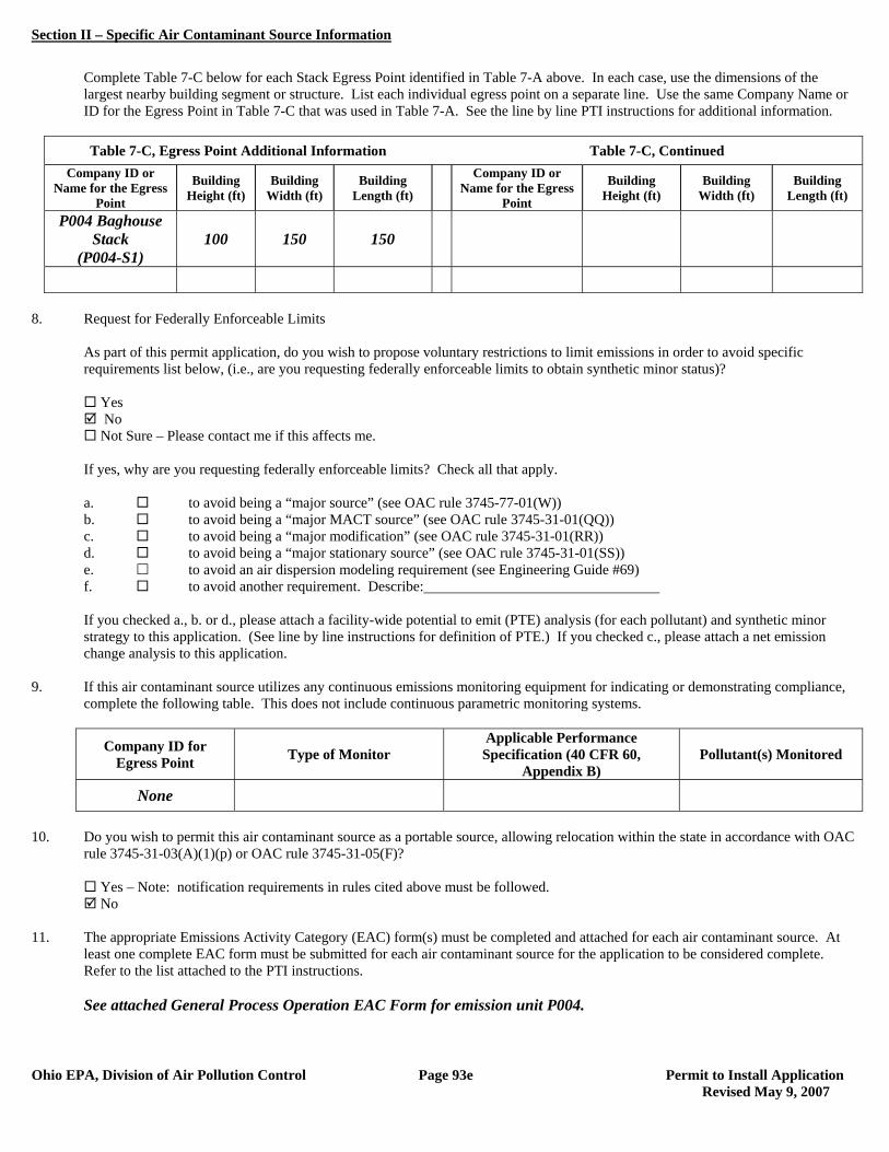
Section II – Specific Air Contaminant Source Information
Ohio EPA, Division of Air Pollution Control Page 93e Permit to Install Application Revised May 9, 2007
Complete Table 7-C below for each Stack Egress Point identified in Table 7-A above. In each case, use the dimensions of the largest nearby building segment or structure. List each individual egress point on a separate line. Use the same Company Name or ID for the Egress Point in Table 7-C that was used in Table 7-A. See the line by line PTI instructions for additional information.
Table 7-C, Egress Point Additional Information Table 7-C, Continued
Company ID or Name for the Egress
Point
Building Height (ft)
Building Width (ft)
Building Length (ft)
Company ID or Name for the Egress
Point
Building Height (ft)
Building Width (ft)
Building Length (ft)
P004 Baghouse Stack
(P004-S1) 100 150 150
8. Request for Federally Enforceable Limits
As part of this permit application, do you wish to propose voluntary restrictions to limit emissions in order to avoid specific requirements list below, (i.e., are you requesting federally enforceable limits to obtain synthetic minor status)?
Yes No Not Sure – Please contact me if this affects me.
If yes, why are you requesting federally enforceable limits? Check all that apply. a. to avoid being a “major source” (see OAC rule 3745-77-01(W)) b. to avoid being a “major MACT source” (see OAC rule 3745-31-01(QQ)) c. to avoid being a “major modification” (see OAC rule 3745-31-01(RR)) d. to avoid being a “major stationary source” (see OAC rule 3745-31-01(SS)) e. to avoid an air dispersion modeling requirement (see Engineering Guide #69) f. to avoid another requirement. Describe: If you checked a., b. or d., please attach a facility-wide potential to emit (PTE) analysis (for each pollutant) and synthetic minor strategy to this application. (See line by line instructions for definition of PTE.) If you checked c., please attach a net emission change analysis to this application.
9. If this air contaminant source utilizes any continuous emissions monitoring equipment for indicating or demonstrating compliance, complete the following table. This does not include continuous parametric monitoring systems.
Company ID for Egress Point Type of Monitor
Applicable Performance Specification (40 CFR 60,
Appendix B) Pollutant(s) Monitored
None
10. Do you wish to permit this air contaminant source as a portable source, allowing relocation within the state in accordance with OAC
rule 3745-31-03(A)(1)(p) or OAC rule 3745-31-05(F)?
Yes – Note: notification requirements in rules cited above must be followed. No
11. The appropriate Emissions Activity Category (EAC) form(s) must be completed and attached for each air contaminant source. At
least one complete EAC form must be submitted for each air contaminant source for the application to be considered complete. Refer to the list attached to the PTI instructions. See attached General Process Operation EAC Form for emission unit P004.
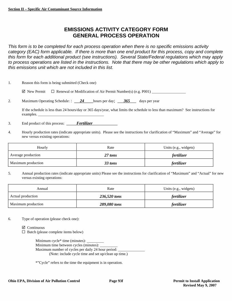
Section II – Specific Air Contaminant Source Information
Ohio EPA, Division of Air Pollution Control Page 93f Permit to Install Application Revised May 9, 2007
EMISSIONS ACTIVITY CATEGORY FORM GENERAL PROCESS OPERATION
This form is to be completed for each process operation when there is no specific emissions activity category (EAC) form applicable. If there is more than one end product for this process, copy and complete this form for each additional product (see instructions). Several State/Federal regulations which may apply to process operations are listed in the instructions. Note that there may be other regulations which apply to this emissions unit which are not included in this list. 1. Reason this form is being submitted (Check one) New Permit Renewal or Modification of Air Permit Number(s) (e.g. P001) 2. Maximum Operating Schedule: : 24 hours per day; 365 days per year
If the schedule is less than 24 hours/day or 365 days/year, what limits the schedule to less than maximum? See instructions for examples.
3. End product of this process: Fertilizer 4. Hourly production rates (indicate appropriate units). Please see the instructions for clarification of “Maximum” and “Average” for
new versus existing operations:
Hourly Rate Units (e.g., widgets)
Average production 27 tons fertilizer
Maximum production 33 tons fertilizer 5. Annual production rates (indicate appropriate units) Please see the instructions for clarification of “Maximum” and “Actual” for new
versus existing operations:
Annual Rate Units (e.g., widgets)
Actual production 236,520 tons fertilizer
Maximum production 289,080 tons fertilizer 6. Type of operation (please check one):
Continuous Batch (please complete items below)
Minimum cycle* time (minutes): Minimum time between cycles (minutes): Maximum number of cycles per daily 24 hour period:
(Note: include cycle time and set up/clean up time.) *”Cycle” refers to the time the equipment is in operation.
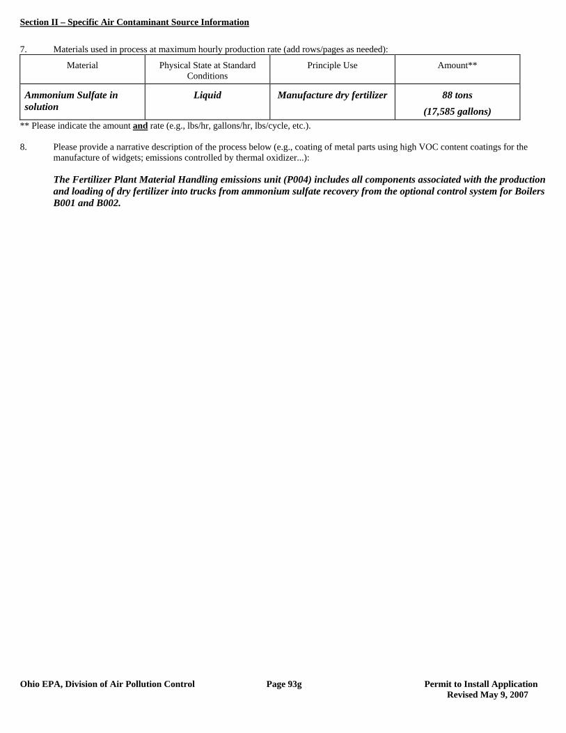
Section II – Specific Air Contaminant Source Information
Ohio EPA, Division of Air Pollution Control Page 93g Permit to Install Application Revised May 9, 2007
7. Materials used in process at maximum hourly production rate (add rows/pages as needed):
Material Physical State at Standard Conditions
Principle Use Amount**
Ammonium Sulfate in solution
Liquid Manufacture dry fertilizer 88 tons (17,585 gallons)
** Please indicate the amount and rate (e.g., lbs/hr, gallons/hr, lbs/cycle, etc.). 8. Please provide a narrative description of the process below (e.g., coating of metal parts using high VOC content coatings for the
manufacture of widgets; emissions controlled by thermal oxidizer...): The Fertilizer Plant Material Handling emissions unit (P004) includes all components associated with the production
and loading of dry fertilizer into trucks from ammonium sulfate recovery from the optional control system for Boilers B001 and B002.

Section II – Specific Air Contaminant Source Information
Ohio EPA, Division of Air Pollution Control Page 94 Permit to Install Application
1. Company identification (name for air contaminant source for which you are applying):
P901 – Coal Barge Unloading 2. List all equipment that are part of this air contaminant source: Coal Barge Unloading, Hopper and Transfer House 3. Air Contaminant Source Installation or Modification Schedule (must be completed regardless of date of installation or modification): When did/will you begin to install or modify the air contaminant source? (month/year) 2009 When did/will you begin to operate the air contaminant source? (month/year) 2012 OR after issuance of PTI 4. Emissions Information: The following table requests information needed to determine the applicable requirements and the compliance status of this air contaminant source with those requirements. Suggestions for how to estimate emissions may be found in the instructions to the Emissions Activity Category (EAC) forms required with this application. If you need further assistance, contact your Ohio EPA permit representative.
If total potential emissions of HAPs or any Air Toxic is greater than 1 ton/yr, fill in the table for that (those) pollutant(s).
For all other pollutants, if ‘Emissions before controls (max), lb/hr’ multiplied by 24 hours/day is greater than 10 lb/day, fill in the table for that pollutant.
If you have no add-on control equipment, ‘Emissions before controls’ will be the same as ‘Actual emissions’. Annual emissions should be based on operating 8760 hr/yr unless you are requesting operating restrictions to limit
emissions in line #8 or have described inherent limitations below. If you use units other than lb/hr or ton/yr, specify the units used (e.g., gr/dscf, lb/ton charged, lb/MMBtu, ton/12-months). Requested Allowable (ton/yr) is often equivalent to Potential to Emit (PTE) as defined in OAC rule 3745-31-01(HHH) and
OAC rule 3745-77-01(BB).
Pollutant Emissions
Before Controls (max) (lb/hr)
Actual Emissions
(lb/hr)
Actual Emissions (ton/year)
Requested Allowable
(lb/hr)
Requested Allowable (ton/year)
PE 12.54 #1.15 #1.60 1.15 1.60
PM10 5.93 #0.54 #0.75 0.54 0.75
Provide your calculations as an attachment and explain how all process variables and emission factors were selected. Note the emissions factor(s) employed and document the origin. Example: AP-42, Table 4.4-3 (8/97); stack test, Method 5, 4/96; mass balance based on MSDS; etc. Refer to the Emissions Calculations section of this permit application.
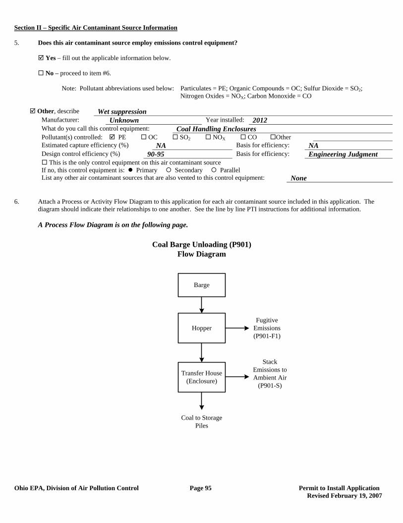
Section II – Specific Air Contaminant Source Information
Ohio EPA, Division of Air Pollution Control Page 95 Permit to Install Application Revised February 19, 2007
5. Does this air contaminant source employ emissions control equipment? Yes – fill out the applicable information below. No – proceed to item #6. Note: Pollutant abbreviations used below: Particulates = PE; Organic Compounds = OC; Sulfur Dioxide = SO2; Nitrogen Oxides = NOX; Carbon Monoxide = CO
Other, describe Wet suppression Manufacturer: Unknown Year installed: 2012 What do you call this control equipment: Coal Handling Enclosures Pollutant(s) controlled: PE OC SO2 NOX CO Other Estimated capture efficiency (%) NA Basis for efficiency: NA Design control efficiency (%) 90-95 Basis for efficiency: Engineering Judgment This is the only control equipment on this air contaminant source If no, this control equipment is: Primary Secondary Parallel List any other air contaminant sources that are also vented to this control equipment: None
6. Attach a Process or Activity Flow Diagram to this application for each air contaminant source included in this application. The
diagram should indicate their relationships to one another. See the line by line PTI instructions for additional information. A Process Flow Diagram is on the following page.
Barge
Transfer House(Enclosure)
Hopper
Stack Emissions to Ambient Air
(P901-S)
Coal Barge Unloading (P901)Flow Diagram
Fugitive Emissions(P901-F1)
Coal to Storage Piles
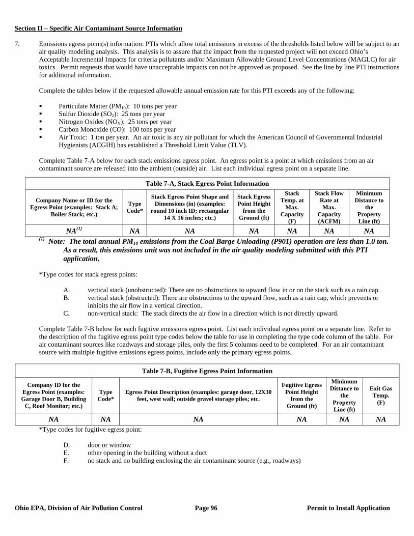
Section II – Specific Air Contaminant Source Information
Ohio EPA, Division of Air Pollution Control Page 96 Permit to Install Application
7. Emissions egress point(s) information: PTIs which allow total emissions in excess of the thresholds listed below will be subject to an
air quality modeling analysis. This analysis is to assure that the impact from the requested project will not exceed Ohio’s Acceptable Incremental Impacts for criteria pollutants and/or Maximum Allowable Ground Level Concentrations (MAGLC) for air toxics. Permit requests that would have unacceptable impacts can not be approved as proposed. See the line by line PTI instructions for additional information.
Complete the tables below if the requested allowable annual emission rate for this PTI exceeds any of the following:
Particulate Matter (PM10): 10 tons per year Sulfur Dioxide (SO2): 25 tons per year Nitrogen Oxides (NOX): 25 tons per year Carbon Monoxide (CO): 100 tons per year Air Toxic: 1 ton per year. An air toxic is any air pollutant for which the American Council of Governmental Industrial
Hygienists (ACGIH) has established a Threshold Limit Value (TLV).
Complete Table 7-A below for each stack emissions egress point. An egress point is a point at which emissions from an air contaminant source are released into the ambient (outside) air. List each individual egress point on a separate line.
(1) Note: The total annual PM10 emissions from the Coal Barge Unloading (P901) operation are less than 1.0 ton. As a result, this emissions unit was not included in the air quality modeling submitted with this PTI application.
*Type codes for stack egress points:
A. vertical stack (unobstructed): There are no obstructions to upward flow in or on the stack such as a rain cap. B. vertical stack (obstructed): There are obstructions to the upward flow, such as a rain cap, which prevents or
inhibits the air flow in a vertical direction. C. non-vertical stack: The stack directs the air flow in a direction which is not directly upward.
Complete Table 7-B below for each fugitive emissions egress point. List each individual egress point on a separate line. Refer to the description of the fugitive egress point type codes below the table for use in completing the type code column of the table. For air contaminant sources like roadways and storage piles, only the first 5 columns need to be completed. For an air contaminant source with multiple fugitive emissions egress points, include only the primary egress points.
Table 7-B, Fugitive Egress Point Information
Company ID for the Egress Point (examples: Garage Door B, Building
C, Roof Monitor; etc.)
Type Code*
Egress Point Description (examples: garage door, 12X30 feet, west wall; outside gravel storage piles; etc.
Fugitive Egress Point Height
from the Ground (ft)
Minimum Distance to
the Property Line (ft)
Exit Gas Temp.
(F)
NA NA NA NA NA NA *Type codes for fugitive egress point:
D. door or window E. other opening in the building without a duct F. no stack and no building enclosing the air contaminant source (e.g., roadways)
Table 7-A, Stack Egress Point Information
Company Name or ID for the Egress Point (examples: Stack A;
Boiler Stack; etc.)
Type Code*
Stack Egress Point Shape and Dimensions (in) (examples:
round 10 inch ID; rectangular 14 X 16 inches; etc.)
Stack Egress Point Height
from the Ground (ft)
Stack Temp. at
Max. Capacity
(F)
Stack Flow Rate at Max.
Capacity (ACFM)
Minimum Distance to
the Property Line (ft)
NA(1) NA NA NA NA NA NA

Section II – Specific Air Contaminant Source Information
Ohio EPA, Division of Air Pollution Control Page 97 Permit to Install Application
Complete Table 7-C below for each Stack Egress Point identified in Table 7-A above. In each case, use the dimensions of the largest nearby building segment or structure. List each individual egress point on a separate line. Use the same Company Name or ID for the Egress Point in Table 7-C that was used in Table 7-A. See the line by line PTI instructions for additional information.
Table 7-C, Egress Point Additional Information Table 7-C, Continued
Company ID or Name for the Egress
Point
Building Height (ft)
Building Width (ft)
Building Length (ft)
Company ID or Name for the Egress
Point
Building Height (ft)
Building Width (ft)
Building Length (ft)
NA NA NA NA 8. Request for Federally Enforceable Limits
As part of this permit application, do you wish to propose voluntary restrictions to limit emissions in order to avoid specific requirements list below, (i.e., are you requesting federally enforceable limits to obtain synthetic minor status)?
Yes No Not Sure – Please contact me if this affects me.
If yes, why are you requesting federally enforceable limits? Check all that apply. a. to avoid being a “major source” (see OAC rule 3745-77-01(W)) b. to avoid being a “major MACT source” (see OAC rule 3745-31-01(QQ)) c. to avoid being a “major modification” (see OAC rule 3745-31-01(RR)) d. to avoid being a “major stationary source” (see OAC rule 3745-31-01(SS)) e. to avoid an air dispersion modeling requirement (see Engineering Guide #69) f. to avoid another requirement. Describe: If you checked a., b. or d., please attach a facility-wide potential to emit (PTE) analysis (for each pollutant) and synthetic minor strategy to this application. (See line by line instructions for definition of PTE.) If you checked c., please attach a net emission change analysis to this application.
9. If this air contaminant source utilizes any continuous emissions monitoring equipment for indicating or demonstrating compliance, complete the following table. This does not include continuous parametric monitoring systems.
Company ID for Egress Point Type of Monitor
Applicable Performance Specification (40 CFR 60,
Appendix B) Pollutant(s) Monitored
None
10. Do you wish to permit this air contaminant source as a portable source, allowing relocation within the state in accordance with OAC
rule 3745-31-03(A)(1)(p) or OAC rule 3745-31-05(F)?
Yes – Note: notification requirements in rules cited above must be followed. No
11. The appropriate Emissions Activity Category (EAC) form(s) must be completed and attached for each air contaminant source. At
least one complete EAC form must be submitted for each air contaminant source for the application to be considered complete. Refer to the list attached to the PTI instructions. See attached General Process Operation EAC Form for emission unit P901.
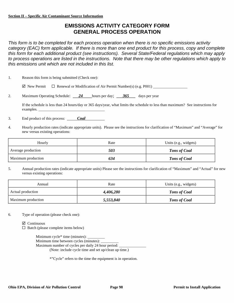
Section II – Specific Air Contaminant Source Information
Ohio EPA, Division of Air Pollution Control Page 98 Permit to Install Application
EMISSIONS ACTIVITY CATEGORY FORM
GENERAL PROCESS OPERATION This form is to be completed for each process operation when there is no specific emissions activity category (EAC) form applicable. If there is more than one end product for this process, copy and complete this form for each additional product (see instructions). Several State/Federal regulations which may apply to process operations are listed in the instructions. Note that there may be other regulations which apply to this emissions unit which are not included in this list. 1. Reason this form is being submitted (Check one): New Permit Renewal or Modification of Air Permit Number(s) (e.g. P001) 2. Maximum Operating Schedule: 24 hours per day; 365 days per year
If the schedule is less than 24 hours/day or 365 days/year, what limits the schedule to less than maximum? See instructions for examples.
3. End product of this process: Coal 4. Hourly production rates (indicate appropriate units). Please see the instructions for clarification of “Maximum” and “Average” for
new versus existing operations:
Hourly Rate Units (e.g., widgets)
Average production 503 Tons of Coal
Maximum production 634 Tons of Coal 5. Annual production rates (indicate appropriate units) Please see the instructions for clarification of “Maximum” and “Actual” for new
versus existing operations:
Annual Rate Units (e.g., widgets)
Actual production 4,406,280 Tons of Coal
Maximum production 5,553,840 Tons of Coal 6. Type of operation (please check one):
Continuous Batch (please complete items below)
Minimum cycle* time (minutes): Minimum time between cycles (minutes): Maximum number of cycles per daily 24 hour period:
(Note: include cycle time and set up/clean up time.)
*”Cycle” refers to the time the equipment is in operation.
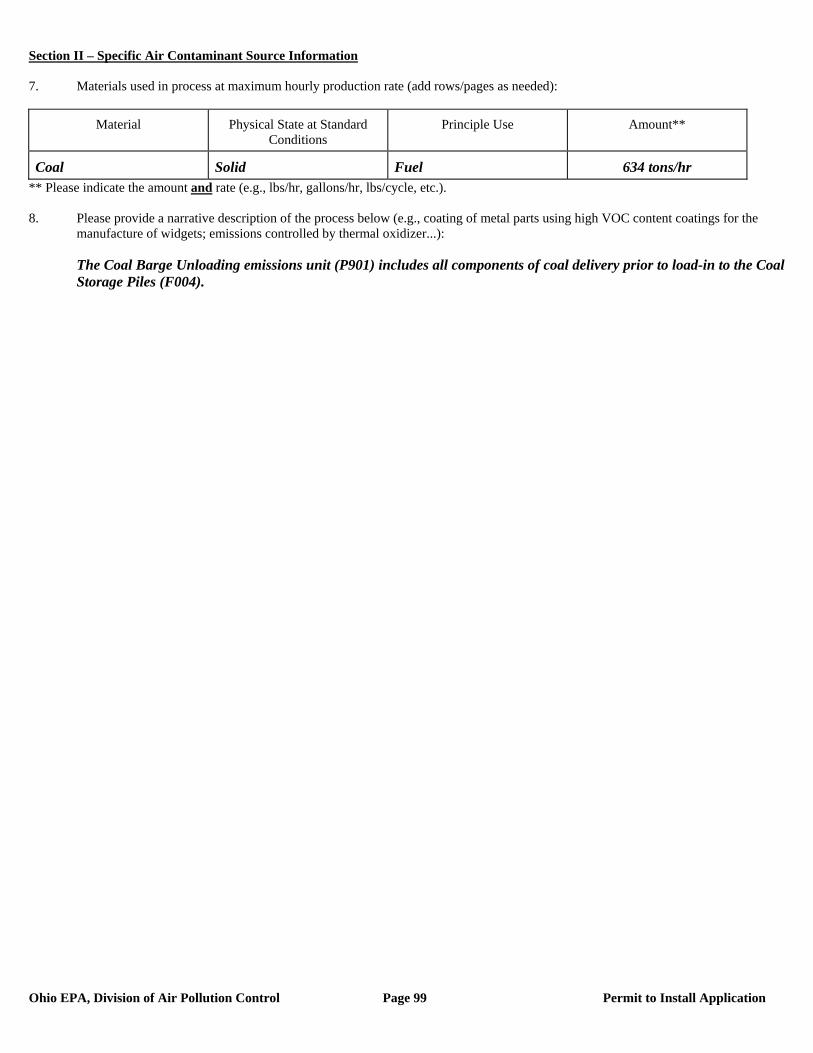
Section II – Specific Air Contaminant Source Information
Ohio EPA, Division of Air Pollution Control Page 99 Permit to Install Application
7. Materials used in process at maximum hourly production rate (add rows/pages as needed):
Material Physical State at Standard Conditions
Principle Use Amount**
Coal Solid Fuel 634 tons/hr ** Please indicate the amount and rate (e.g., lbs/hr, gallons/hr, lbs/cycle, etc.). 8. Please provide a narrative description of the process below (e.g., coating of metal parts using high VOC content coatings for the
manufacture of widgets; emissions controlled by thermal oxidizer...): The Coal Barge Unloading emissions unit (P901) includes all components of coal delivery prior to load-in to the Coal
Storage Piles (F004).
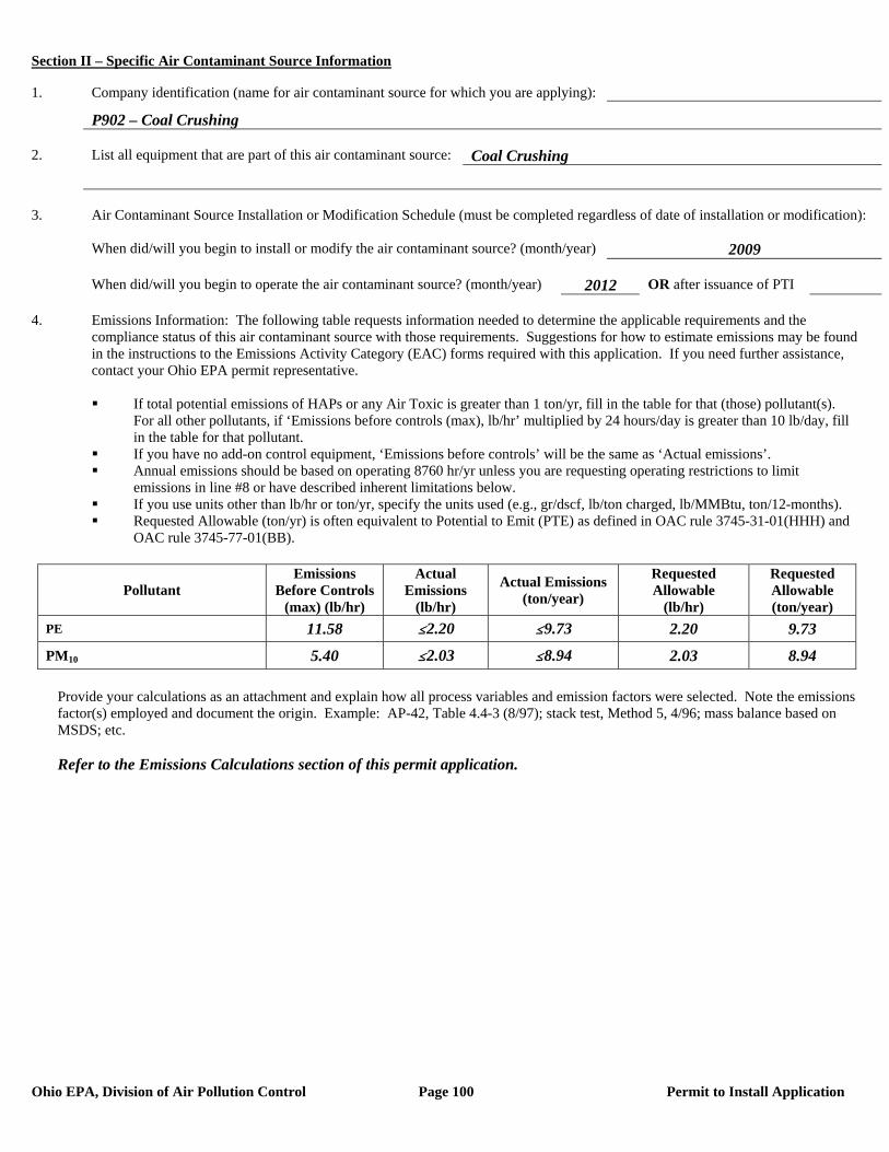
Section II – Specific Air Contaminant Source Information
Ohio EPA, Division of Air Pollution Control Page 100 Permit to Install Application
1. Company identification (name for air contaminant source for which you are applying):
P902 – Coal Crushing 2. List all equipment that are part of this air contaminant source: Coal Crushing 3. Air Contaminant Source Installation or Modification Schedule (must be completed regardless of date of installation or modification): When did/will you begin to install or modify the air contaminant source? (month/year) 2009 When did/will you begin to operate the air contaminant source? (month/year) 2012 OR after issuance of PTI 4. Emissions Information: The following table requests information needed to determine the applicable requirements and the compliance status of this air contaminant source with those requirements. Suggestions for how to estimate emissions may be found in the instructions to the Emissions Activity Category (EAC) forms required with this application. If you need further assistance, contact your Ohio EPA permit representative.
If total potential emissions of HAPs or any Air Toxic is greater than 1 ton/yr, fill in the table for that (those) pollutant(s).
For all other pollutants, if ‘Emissions before controls (max), lb/hr’ multiplied by 24 hours/day is greater than 10 lb/day, fill in the table for that pollutant.
If you have no add-on control equipment, ‘Emissions before controls’ will be the same as ‘Actual emissions’. Annual emissions should be based on operating 8760 hr/yr unless you are requesting operating restrictions to limit
emissions in line #8 or have described inherent limitations below. If you use units other than lb/hr or ton/yr, specify the units used (e.g., gr/dscf, lb/ton charged, lb/MMBtu, ton/12-months). Requested Allowable (ton/yr) is often equivalent to Potential to Emit (PTE) as defined in OAC rule 3745-31-01(HHH) and
OAC rule 3745-77-01(BB).
Pollutant Emissions
Before Controls (max) (lb/hr)
Actual Emissions
(lb/hr)
Actual Emissions (ton/year)
Requested Allowable
(lb/hr)
Requested Allowable (ton/year)
PE 11.58 #2.20 #9.73 2.20 9.73
PM10 5.40 #2.03 #8.94 2.03 8.94
Provide your calculations as an attachment and explain how all process variables and emission factors were selected. Note the emissions factor(s) employed and document the origin. Example: AP-42, Table 4.4-3 (8/97); stack test, Method 5, 4/96; mass balance based on MSDS; etc. Refer to the Emissions Calculations section of this permit application.
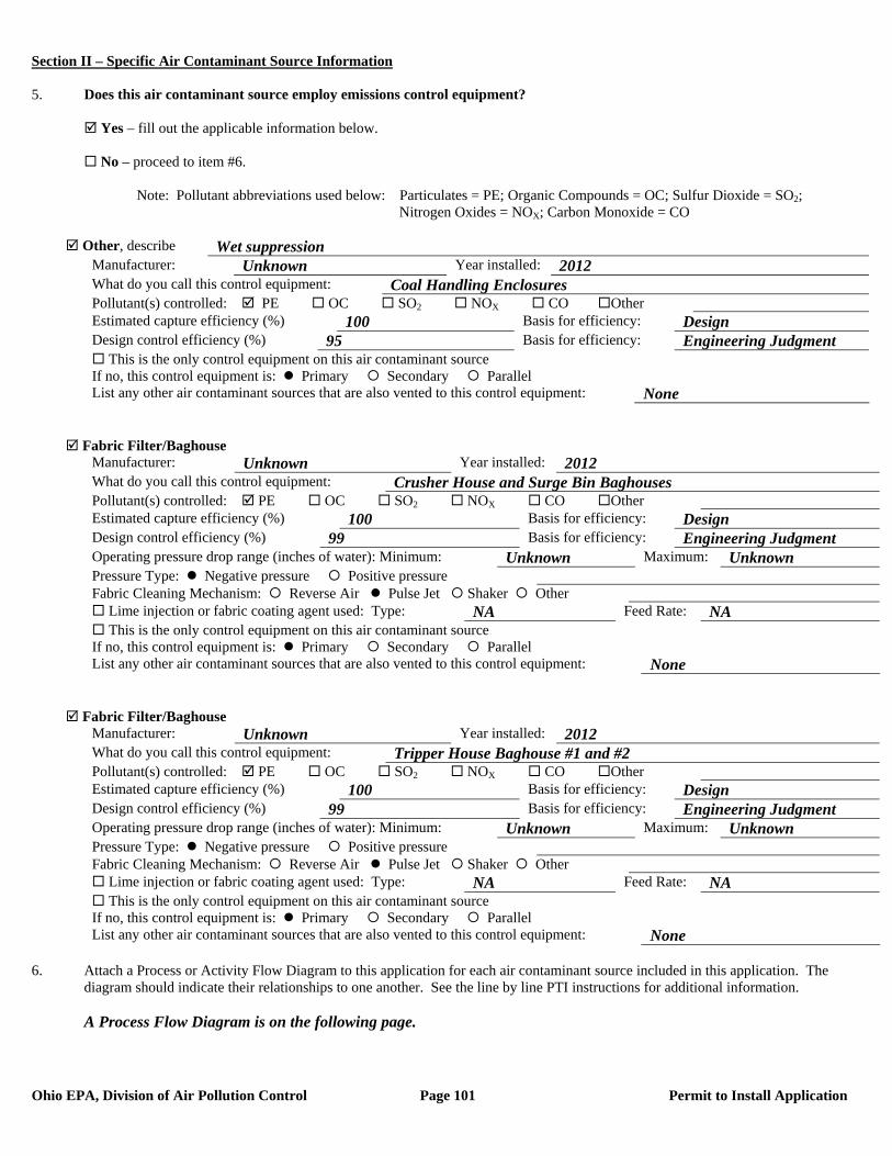
Section II – Specific Air Contaminant Source Information
Ohio EPA, Division of Air Pollution Control Page 101 Permit to Install Application
5. Does this air contaminant source employ emissions control equipment? Yes – fill out the applicable information below. No – proceed to item #6. Note: Pollutant abbreviations used below: Particulates = PE; Organic Compounds = OC; Sulfur Dioxide = SO2; Nitrogen Oxides = NOX; Carbon Monoxide = CO
Other, describe Wet suppression Manufacturer: Unknown Year installed: 2012 What do you call this control equipment: Coal Handling Enclosures Pollutant(s) controlled: PE OC SO2 NOX CO Other Estimated capture efficiency (%) 100 Basis for efficiency: Design Design control efficiency (%) 95 Basis for efficiency: Engineering Judgment This is the only control equipment on this air contaminant source If no, this control equipment is: Primary Secondary Parallel List any other air contaminant sources that are also vented to this control equipment: None
Fabric Filter/Baghouse Manufacturer: Unknown Year installed: 2012 What do you call this control equipment: Crusher House and Surge Bin Baghouses Pollutant(s) controlled: PE OC SO2 NOX CO Other Estimated capture efficiency (%) 100 Basis for efficiency: Design Design control efficiency (%) 99 Basis for efficiency: Engineering Judgment Operating pressure drop range (inches of water): Minimum: Unknown Maximum: Unknown Pressure Type: Negative pressure Positive pressure Fabric Cleaning Mechanism: Reverse Air Pulse Jet Shaker Other Lime injection or fabric coating agent used: Type: NA Feed Rate: NA This is the only control equipment on this air contaminant source If no, this control equipment is: Primary Secondary Parallel List any other air contaminant sources that are also vented to this control equipment: None
Fabric Filter/Baghouse Manufacturer: Unknown Year installed: 2012 What do you call this control equipment: Tripper House Baghouse #1 and #2 Pollutant(s) controlled: PE OC SO2 NOX CO Other Estimated capture efficiency (%) 100 Basis for efficiency: Design Design control efficiency (%) 99 Basis for efficiency: Engineering Judgment Operating pressure drop range (inches of water): Minimum: Unknown Maximum: Unknown Pressure Type: Negative pressure Positive pressure Fabric Cleaning Mechanism: Reverse Air Pulse Jet Shaker Other Lime injection or fabric coating agent used: Type: NA Feed Rate: NA This is the only control equipment on this air contaminant source If no, this control equipment is: Primary Secondary Parallel List any other air contaminant sources that are also vented to this control equipment: None
6. Attach a Process or Activity Flow Diagram to this application for each air contaminant source included in this application. The
diagram should indicate their relationships to one another. See the line by line PTI instructions for additional information. A Process Flow Diagram is on the following page.
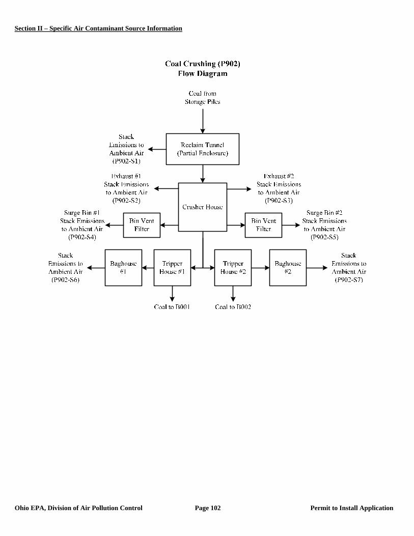
Section II – Specific Air Contaminant Source Information
Ohio EPA, Division of Air Pollution Control Page 102 Permit to Install Application
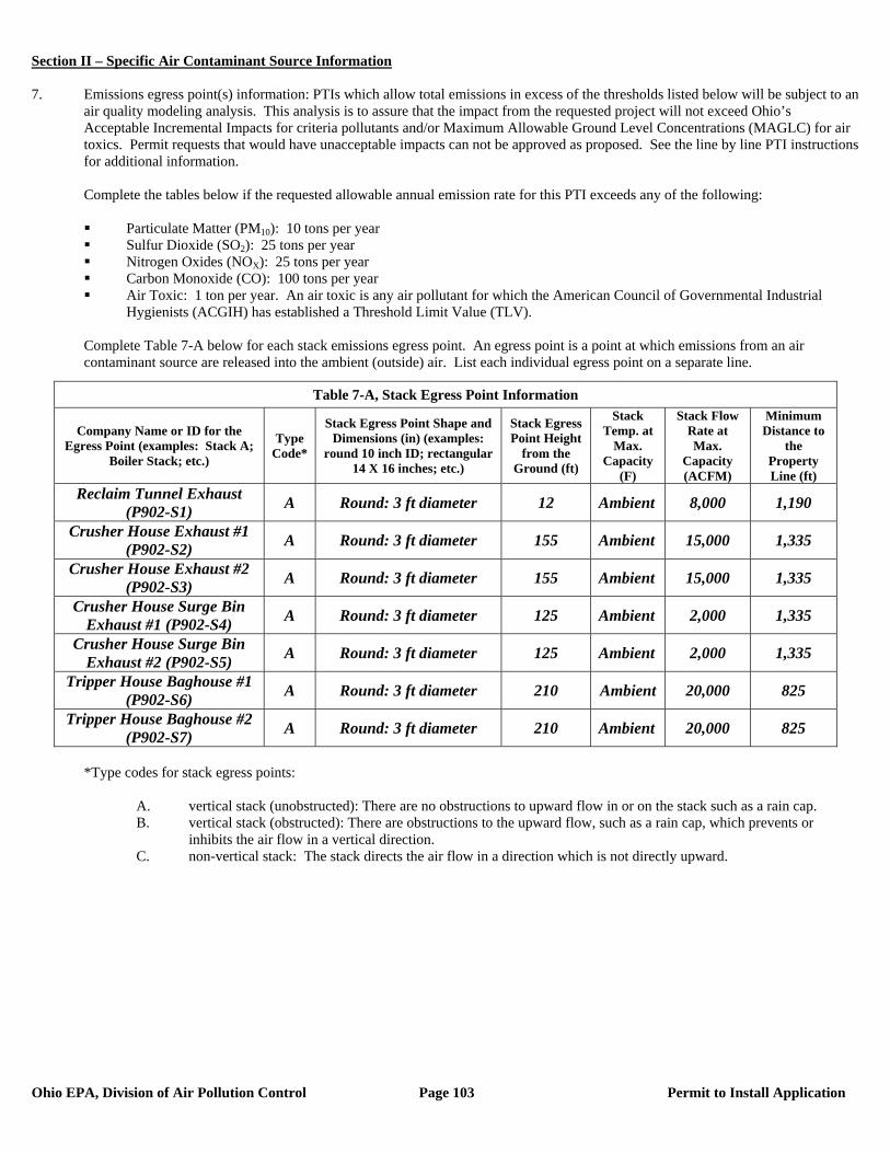
Section II – Specific Air Contaminant Source Information
Ohio EPA, Division of Air Pollution Control Page 103 Permit to Install Application
7. Emissions egress point(s) information: PTIs which allow total emissions in excess of the thresholds listed below will be subject to an
air quality modeling analysis. This analysis is to assure that the impact from the requested project will not exceed Ohio’s Acceptable Incremental Impacts for criteria pollutants and/or Maximum Allowable Ground Level Concentrations (MAGLC) for air toxics. Permit requests that would have unacceptable impacts can not be approved as proposed. See the line by line PTI instructions for additional information.
Complete the tables below if the requested allowable annual emission rate for this PTI exceeds any of the following:
Particulate Matter (PM10): 10 tons per year Sulfur Dioxide (SO2): 25 tons per year Nitrogen Oxides (NOX): 25 tons per year Carbon Monoxide (CO): 100 tons per year Air Toxic: 1 ton per year. An air toxic is any air pollutant for which the American Council of Governmental Industrial
Hygienists (ACGIH) has established a Threshold Limit Value (TLV).
Complete Table 7-A below for each stack emissions egress point. An egress point is a point at which emissions from an air contaminant source are released into the ambient (outside) air. List each individual egress point on a separate line.
*Type codes for stack egress points:
A. vertical stack (unobstructed): There are no obstructions to upward flow in or on the stack such as a rain cap. B. vertical stack (obstructed): There are obstructions to the upward flow, such as a rain cap, which prevents or
inhibits the air flow in a vertical direction. C. non-vertical stack: The stack directs the air flow in a direction which is not directly upward.
Table 7-A, Stack Egress Point Information
Company Name or ID for the Egress Point (examples: Stack A;
Boiler Stack; etc.)
Type Code*
Stack Egress Point Shape and Dimensions (in) (examples:
round 10 inch ID; rectangular 14 X 16 inches; etc.)
Stack Egress Point Height
from the Ground (ft)
Stack Temp. at
Max. Capacity
(F)
Stack Flow Rate at Max.
Capacity (ACFM)
Minimum Distance to
the Property Line (ft)
Reclaim Tunnel Exhaust (P902-S1) A Round: 3 ft diameter 12 Ambient 8,000 1,190
Crusher House Exhaust #1 (P902-S2) A Round: 3 ft diameter 155 Ambient 15,000 1,335
Crusher House Exhaust #2 (P902-S3) A Round: 3 ft diameter 155 Ambient 15,000 1,335
Crusher House Surge Bin Exhaust #1 (P902-S4) A Round: 3 ft diameter 125 Ambient 2,000 1,335
Crusher House Surge Bin Exhaust #2 (P902-S5) A Round: 3 ft diameter 125 Ambient 2,000 1,335
Tripper House Baghouse #1 (P902-S6) A Round: 3 ft diameter 210 Ambient 20,000 825
Tripper House Baghouse #2 (P902-S7) A Round: 3 ft diameter 210 Ambient 20,000 825
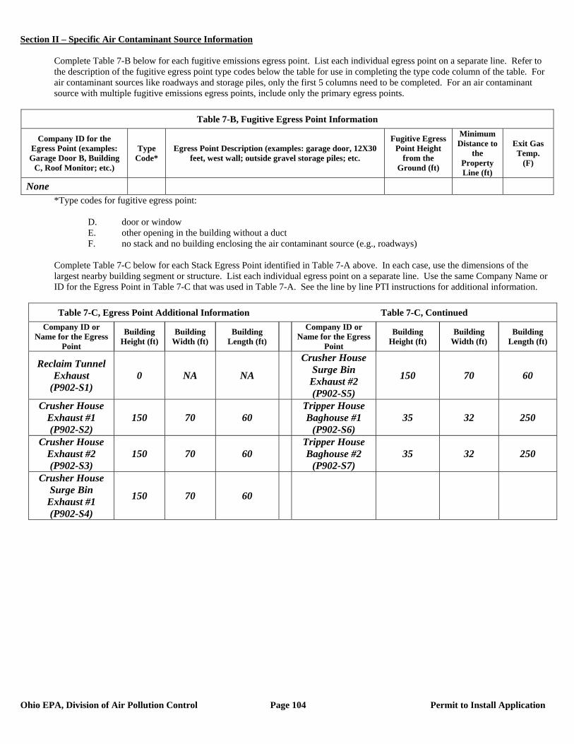
Section II – Specific Air Contaminant Source Information
Ohio EPA, Division of Air Pollution Control Page 104 Permit to Install Application
Complete Table 7-B below for each fugitive emissions egress point. List each individual egress point on a separate line. Refer to the description of the fugitive egress point type codes below the table for use in completing the type code column of the table. For air contaminant sources like roadways and storage piles, only the first 5 columns need to be completed. For an air contaminant source with multiple fugitive emissions egress points, include only the primary egress points.
Table 7-B, Fugitive Egress Point Information
Company ID for the Egress Point (examples: Garage Door B, Building
C, Roof Monitor; etc.)
Type Code*
Egress Point Description (examples: garage door, 12X30 feet, west wall; outside gravel storage piles; etc.
Fugitive Egress Point Height
from the Ground (ft)
Minimum Distance to
the Property Line (ft)
Exit Gas Temp.
(F)
None *Type codes for fugitive egress point:
D. door or window E. other opening in the building without a duct F. no stack and no building enclosing the air contaminant source (e.g., roadways)
Complete Table 7-C below for each Stack Egress Point identified in Table 7-A above. In each case, use the dimensions of the largest nearby building segment or structure. List each individual egress point on a separate line. Use the same Company Name or ID for the Egress Point in Table 7-C that was used in Table 7-A. See the line by line PTI instructions for additional information.
Table 7-C, Egress Point Additional Information Table 7-C, Continued
Company ID or Name for the Egress
Point
Building Height (ft)
Building Width (ft)
Building Length (ft)
Company ID or Name for the Egress
Point
Building Height (ft)
Building Width (ft)
Building Length (ft)
Reclaim Tunnel Exhaust
(P902-S1) 0 NA NA
Crusher House Surge Bin
Exhaust #2 (P902-S5)
150 70 60
Crusher House Exhaust #1 (P902-S2)
150 70 60 Tripper House Baghouse #1
(P902-S6) 35 32 250
Crusher House Exhaust #2 (P902-S3)
150 70 60 Tripper House Baghouse #2
(P902-S7) 35 32 250
Crusher House Surge Bin
Exhaust #1 (P902-S4)
150 70 60
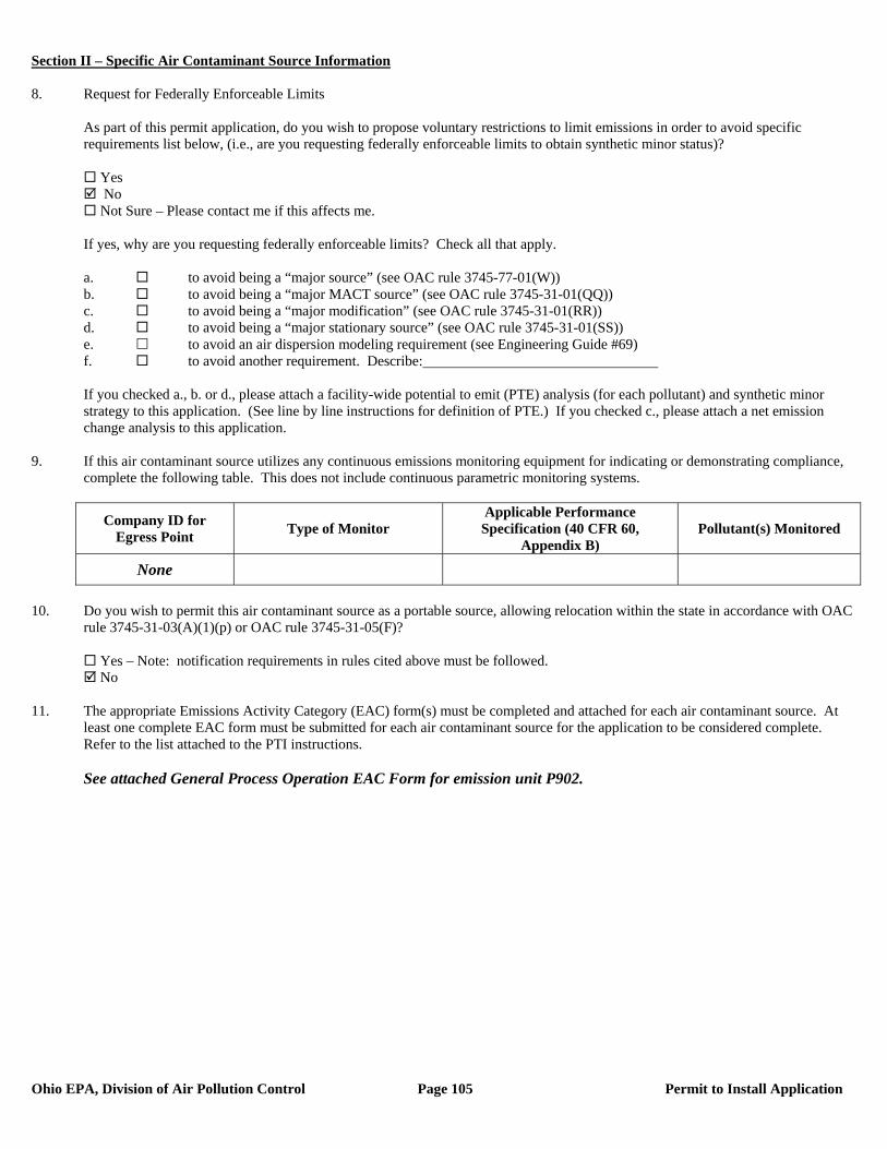
Section II – Specific Air Contaminant Source Information
Ohio EPA, Division of Air Pollution Control Page 105 Permit to Install Application
8. Request for Federally Enforceable Limits
As part of this permit application, do you wish to propose voluntary restrictions to limit emissions in order to avoid specific requirements list below, (i.e., are you requesting federally enforceable limits to obtain synthetic minor status)?
Yes No Not Sure – Please contact me if this affects me.
If yes, why are you requesting federally enforceable limits? Check all that apply. a. to avoid being a “major source” (see OAC rule 3745-77-01(W)) b. to avoid being a “major MACT source” (see OAC rule 3745-31-01(QQ)) c. to avoid being a “major modification” (see OAC rule 3745-31-01(RR)) d. to avoid being a “major stationary source” (see OAC rule 3745-31-01(SS)) e. to avoid an air dispersion modeling requirement (see Engineering Guide #69) f. to avoid another requirement. Describe: If you checked a., b. or d., please attach a facility-wide potential to emit (PTE) analysis (for each pollutant) and synthetic minor strategy to this application. (See line by line instructions for definition of PTE.) If you checked c., please attach a net emission change analysis to this application.
9. If this air contaminant source utilizes any continuous emissions monitoring equipment for indicating or demonstrating compliance, complete the following table. This does not include continuous parametric monitoring systems.
Company ID for Egress Point Type of Monitor
Applicable Performance Specification (40 CFR 60,
Appendix B) Pollutant(s) Monitored
None
10. Do you wish to permit this air contaminant source as a portable source, allowing relocation within the state in accordance with OAC
rule 3745-31-03(A)(1)(p) or OAC rule 3745-31-05(F)?
Yes – Note: notification requirements in rules cited above must be followed. No
11. The appropriate Emissions Activity Category (EAC) form(s) must be completed and attached for each air contaminant source. At
least one complete EAC form must be submitted for each air contaminant source for the application to be considered complete. Refer to the list attached to the PTI instructions. See attached General Process Operation EAC Form for emission unit P902.
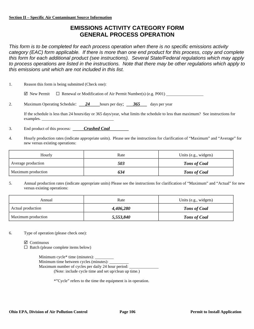
Section II – Specific Air Contaminant Source Information
Ohio EPA, Division of Air Pollution Control Page 106 Permit to Install Application
EMISSIONS ACTIVITY CATEGORY FORM
GENERAL PROCESS OPERATION This form is to be completed for each process operation when there is no specific emissions activity category (EAC) form applicable. If there is more than one end product for this process, copy and complete this form for each additional product (see instructions). Several State/Federal regulations which may apply to process operations are listed in the instructions. Note that there may be other regulations which apply to this emissions unit which are not included in this list. 1. Reason this form is being submitted (Check one): New Permit Renewal or Modification of Air Permit Number(s) (e.g. P001) 2. Maximum Operating Schedule: 24 hours per day; 365 days per year
If the schedule is less than 24 hours/day or 365 days/year, what limits the schedule to less than maximum? See instructions for examples.
3. End product of this process: Crushed Coal 4. Hourly production rates (indicate appropriate units). Please see the instructions for clarification of “Maximum” and “Average” for
new versus existing operations:
Hourly Rate Units (e.g., widgets)
Average production 503 Tons of Coal
Maximum production 634 Tons of Coal 5. Annual production rates (indicate appropriate units) Please see the instructions for clarification of “Maximum” and “Actual” for new
versus existing operations:
Annual Rate Units (e.g., widgets)
Actual production 4,406,280 Tons of Coal
Maximum production 5,553,840 Tons of Coal 6. Type of operation (please check one):
Continuous Batch (please complete items below)
Minimum cycle* time (minutes): Minimum time between cycles (minutes): Maximum number of cycles per daily 24 hour period:
(Note: include cycle time and set up/clean up time.)
*”Cycle” refers to the time the equipment is in operation.
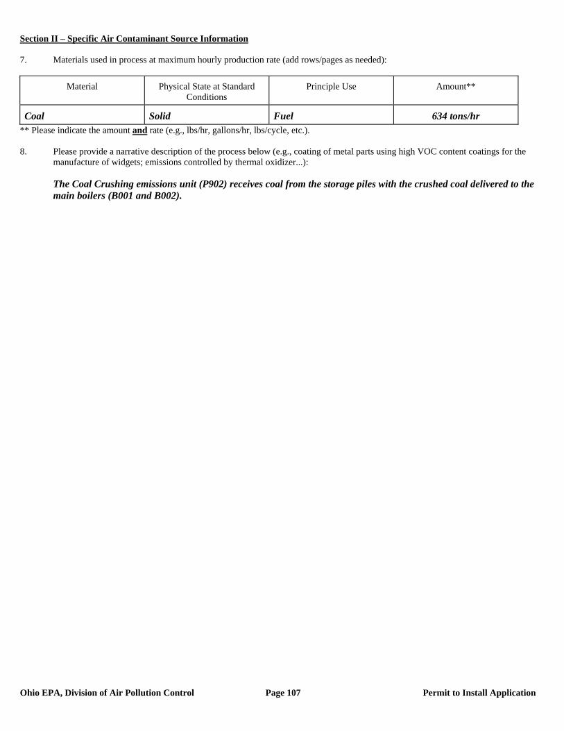
Section II – Specific Air Contaminant Source Information
Ohio EPA, Division of Air Pollution Control Page 107 Permit to Install Application
7. Materials used in process at maximum hourly production rate (add rows/pages as needed):
Material Physical State at Standard Conditions
Principle Use Amount**
Coal Solid Fuel 634 tons/hr ** Please indicate the amount and rate (e.g., lbs/hr, gallons/hr, lbs/cycle, etc.). 8. Please provide a narrative description of the process below (e.g., coating of metal parts using high VOC content coatings for the
manufacture of widgets; emissions controlled by thermal oxidizer...): The Coal Crushing emissions unit (P902) receives coal from the storage piles with the crushed coal delivered to the
main boilers (B001 and B002).
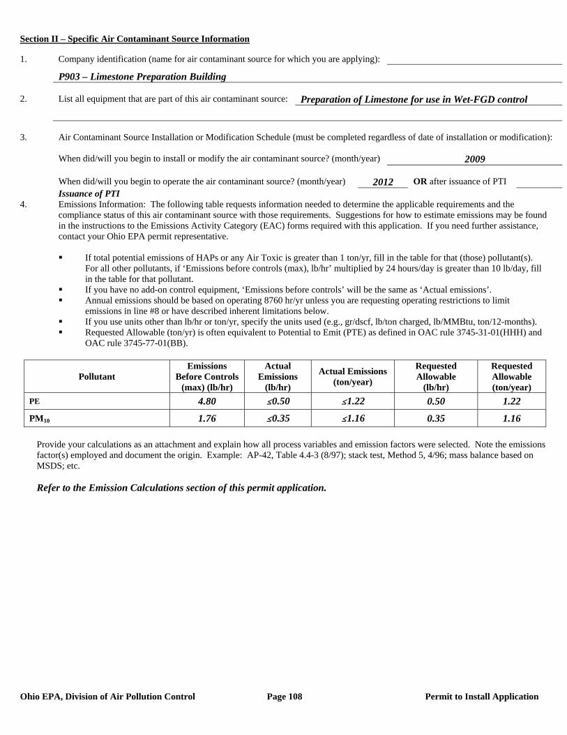
Section II – Specific Air Contaminant Source Information
Ohio EPA, Division of Air Pollution Control Page 108 Permit to Install Application
1. Company identification (name for air contaminant source for which you are applying):
P903 – Limestone Preparation Building 2. List all equipment that are part of this air contaminant source: Preparation of Limestone for use in Wet-FGD control 3. Air Contaminant Source Installation or Modification Schedule (must be completed regardless of date of installation or modification): When did/will you begin to install or modify the air contaminant source? (month/year) 2009 When did/will you begin to operate the air contaminant source? (month/year) 2012 OR after issuance of PTI Issuance of PTI 4. Emissions Information: The following table requests information needed to determine the applicable requirements and the compliance status of this air contaminant source with those requirements. Suggestions for how to estimate emissions may be found in the instructions to the Emissions Activity Category (EAC) forms required with this application. If you need further assistance, contact your Ohio EPA permit representative.
If total potential emissions of HAPs or any Air Toxic is greater than 1 ton/yr, fill in the table for that (those) pollutant(s).
For all other pollutants, if ‘Emissions before controls (max), lb/hr’ multiplied by 24 hours/day is greater than 10 lb/day, fill in the table for that pollutant.
If you have no add-on control equipment, ‘Emissions before controls’ will be the same as ‘Actual emissions’. Annual emissions should be based on operating 8760 hr/yr unless you are requesting operating restrictions to limit
emissions in line #8 or have described inherent limitations below. If you use units other than lb/hr or ton/yr, specify the units used (e.g., gr/dscf, lb/ton charged, lb/MMBtu, ton/12-months). Requested Allowable (ton/yr) is often equivalent to Potential to Emit (PTE) as defined in OAC rule 3745-31-01(HHH) and
OAC rule 3745-77-01(BB).
Pollutant Emissions
Before Controls (max) (lb/hr)
Actual Emissions
(lb/hr)
Actual Emissions (ton/year)
Requested Allowable
(lb/hr)
Requested Allowable (ton/year)
PE 4.80 #0.50 #1.22 0.50 1.22
PM10 1.76 #0.35 #1.16 0.35 1.16
Provide your calculations as an attachment and explain how all process variables and emission factors were selected. Note the emissions factor(s) employed and document the origin. Example: AP-42, Table 4.4-3 (8/97); stack test, Method 5, 4/96; mass balance based on MSDS; etc.
Refer to the Emission Calculations section of this permit application.
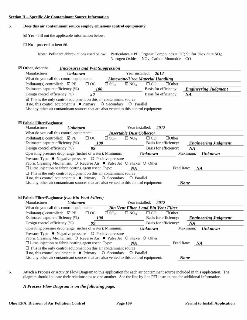
Section II – Specific Air Contaminant Source Information
Ohio EPA, Division of Air Pollution Control Page 109 Permit to Install Application
5. Does this air contaminant source employ emissions control equipment? Yes – fill out the applicable information below. No – proceed to item #6. Note: Pollutant abbreviations used below: Particulates = PE; Organic Compounds = OC; Sulfur Dioxide = SO2; Nitrogen Oxides = NOX; Carbon Monoxide = CO
Other, describe Enclosures and Wet Suppression Manufacturer: Unknown Year installed: 2012 What do you call this control equipment: Limestone/Urea Material Handling Pollutant(s) controlled: PE OC SO2 NOX CO Other Estimated capture efficiency (%) 100 Basis for efficiency: Engineering Judgment Design control efficiency (%) 50 Basis for efficiency: NA This is the only control equipment on this air contaminant source If no, this control equipment is: Primary Secondary Parallel List any other air contaminant sources that are also vented to this control equipment:
Fabric Filter/Baghouse Manufacturer: Unknown Year installed: 2012 What do you call this control equipment: Insertable Dust Collector Pollutant(s) controlled: PE OC SO2 NOX CO Other Estimated capture efficiency (%) 100 Basis for efficiency: Engineering Judgment Design control efficiency (%) 99 Basis for efficiency: NA Operating pressure drop range (inches of water): Minimum: Unknown Maximum: Unknown Pressure Type: Negative pressure Positive pressure Fabric Cleaning Mechanism: Reverse Air Pulse Jet Shaker Other Lime injection or fabric coating agent used: Type: NA Feed Rate: NA This is the only control equipment on this air contaminant source If no, this control equipment is: Primary Secondary Parallel List any other air contaminant sources that are also vented to this control equipment: None
Fabric Filter/Baghouse (two Bin Vent Filters) Manufacturer: Unknown Year installed: 2012 What do you call this control equipment: Bin Vent Filter 1 and Bin Vent Filter Pollutant(s) controlled: PE OC SO2 NOX CO Other Estimated capture efficiency (%) 100 Basis for efficiency: Engineering Judgment Design control efficiency (%) 99 Basis for efficiency: NA Operating pressure drop range (inches of water): Minimum: Unknown Maximum: Unknown Pressure Type: Negative pressure Positive pressure Fabric Cleaning Mechanism: Reverse Air Pulse Jet Shaker Other Lime injection or fabric coating agent used: Type: NA Feed Rate: NA This is the only control equipment on this air contaminant source If no, this control equipment is: Primary Secondary Parallel List any other air contaminant sources that are also vented to this control equipment: None
6. Attach a Process or Activity Flow Diagram to this application for each air contaminant source included in this application. The
diagram should indicate their relationships to one another. See the line by line PTI instructions for additional information. A Process Flow Diagram is on the following page.
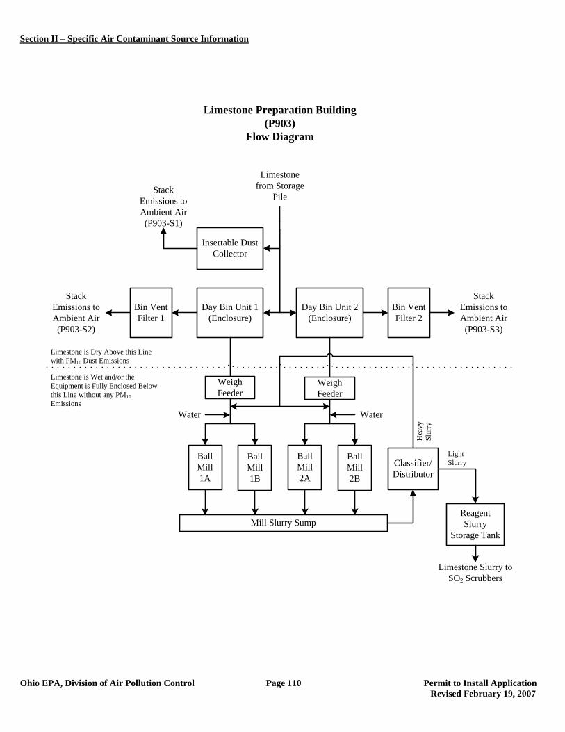
Section II – Specific Air Contaminant Source Information
Ohio EPA, Division of Air Pollution Control Page 110 Permit to Install Application Revised February 19, 2007
Day Bin Unit 1(Enclosure)
Day Bin Unit 2(Enclosure)
Limestone Slurry to SO2 Scrubbers
Limestone Preparation Building (P903)
Flow Diagram
Stack Emissions to Ambient Air(P903-S2)
Stack Emissions to Ambient Air(P903-S3)
Insertable Dust Collector
Stack Emissions to Ambient Air(P903-S1)
Bin Vent Filter 1
Bin Vent Filter 2
Limestone from Storage
Pile
Ball Mill1A
Mill Slurry Sump
Water
Ball Mill1B
Ball Mill2A
Ball Mill2B
Water
Limestone is Dry Above this Line with PM10 Dust Emissions
Limestone is Wet and/or the Equipment is Fully Enclosed Below this Line without any PM10Emissions
Weigh Feeder
Weigh Feeder
Classifier/Distributor
Reagent Slurry
Storage Tank
Hea
vySl
urry
LightSlurry
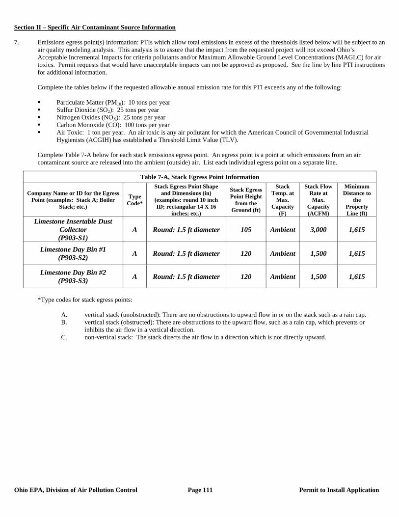
Section II – Specific Air Contaminant Source Information
Ohio EPA, Division of Air Pollution Control Page 111 Permit to Install Application
7. Emissions egress point(s) information: PTIs which allow total emissions in excess of the thresholds listed below will be subject to an
air quality modeling analysis. This analysis is to assure that the impact from the requested project will not exceed Ohio’s Acceptable Incremental Impacts for criteria pollutants and/or Maximum Allowable Ground Level Concentrations (MAGLC) for air toxics. Permit requests that would have unacceptable impacts can not be approved as proposed. See the line by line PTI instructions for additional information.
Complete the tables below if the requested allowable annual emission rate for this PTI exceeds any of the following:
Particulate Matter (PM10): 10 tons per year Sulfur Dioxide (SO2): 25 tons per year Nitrogen Oxides (NOX): 25 tons per year Carbon Monoxide (CO): 100 tons per year Air Toxic: 1 ton per year. An air toxic is any air pollutant for which the American Council of Governmental Industrial
Hygienists (ACGIH) has established a Threshold Limit Value (TLV).
Complete Table 7-A below for each stack emissions egress point. An egress point is a point at which emissions from an air contaminant source are released into the ambient (outside) air. List each individual egress point on a separate line.
*Type codes for stack egress points:
A. vertical stack (unobstructed): There are no obstructions to upward flow in or on the stack such as a rain cap. B. vertical stack (obstructed): There are obstructions to the upward flow, such as a rain cap, which prevents or
inhibits the air flow in a vertical direction. C. non-vertical stack: The stack directs the air flow in a direction which is not directly upward.
Table 7-A, Stack Egress Point Information
Company Name or ID for the Egress Point (examples: Stack A; Boiler
Stack; etc.)
Type Code*
Stack Egress Point Shape and Dimensions (in)
(examples: round 10 inch ID; rectangular 14 X 16
inches; etc.)
Stack Egress Point Height
from the Ground (ft)
Stack Temp. at
Max. Capacity
(F)
Stack Flow Rate at Max.
Capacity (ACFM)
Minimum Distance to
the Property Line (ft)
Limestone Insertable Dust Collector (P903-S1)
A Round: 1.5 ft diameter 105 Ambient 3,000 1,615
Limestone Day Bin #1 (P903-S2) A Round: 1.5 ft diameter 120 Ambient 1,500 1,615
Limestone Day Bin #2 (P903-S3) A Round: 1.5 ft diameter 120 Ambient 1,500 1,615
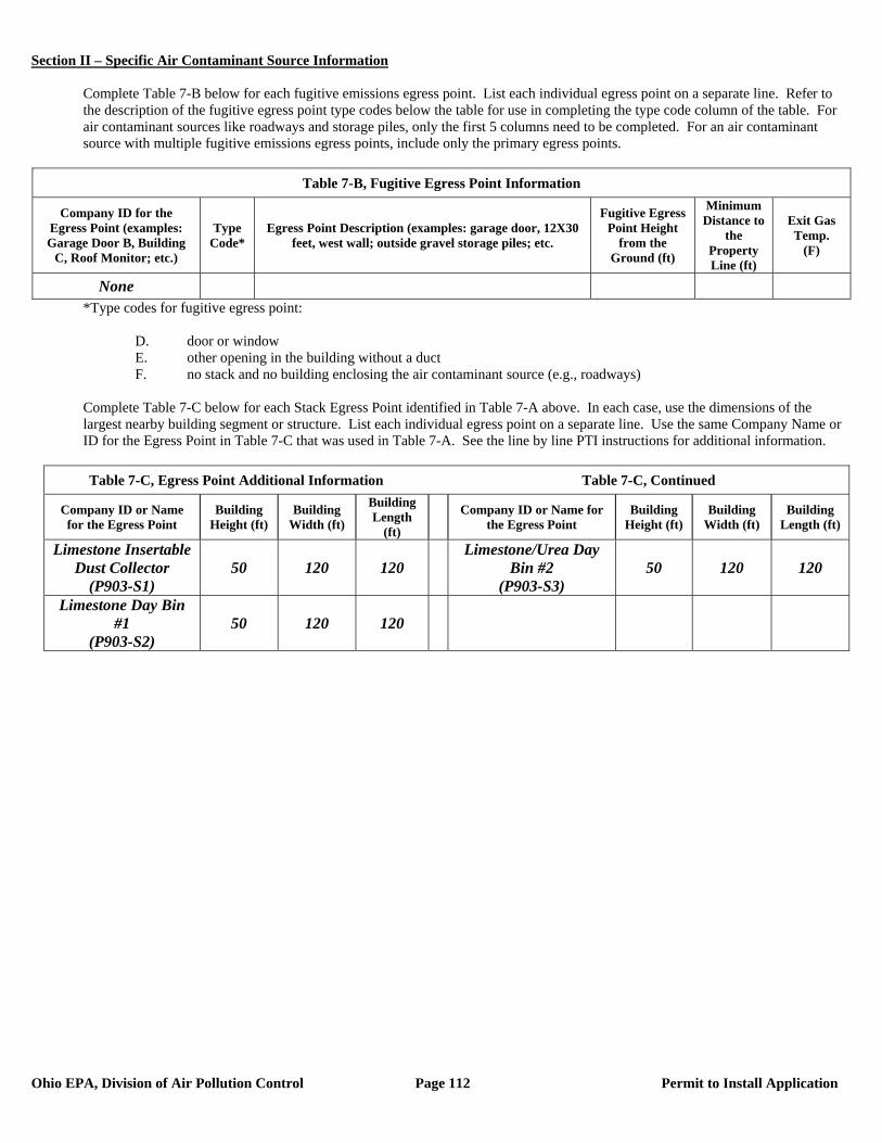
Section II – Specific Air Contaminant Source Information
Ohio EPA, Division of Air Pollution Control Page 112 Permit to Install Application
Complete Table 7-B below for each fugitive emissions egress point. List each individual egress point on a separate line. Refer to the description of the fugitive egress point type codes below the table for use in completing the type code column of the table. For air contaminant sources like roadways and storage piles, only the first 5 columns need to be completed. For an air contaminant source with multiple fugitive emissions egress points, include only the primary egress points.
Table 7-B, Fugitive Egress Point Information
Company ID for the Egress Point (examples: Garage Door B, Building
C, Roof Monitor; etc.)
Type Code*
Egress Point Description (examples: garage door, 12X30 feet, west wall; outside gravel storage piles; etc.
Fugitive Egress Point Height
from the Ground (ft)
Minimum Distance to
the Property Line (ft)
Exit Gas Temp.
(F)
None *Type codes for fugitive egress point:
D. door or window E. other opening in the building without a duct F. no stack and no building enclosing the air contaminant source (e.g., roadways)
Complete Table 7-C below for each Stack Egress Point identified in Table 7-A above. In each case, use the dimensions of the largest nearby building segment or structure. List each individual egress point on a separate line. Use the same Company Name or ID for the Egress Point in Table 7-C that was used in Table 7-A. See the line by line PTI instructions for additional information.
Table 7-C, Egress Point Additional Information Table 7-C, Continued
Company ID or Name for the Egress Point
Building Height (ft)
Building Width (ft)
Building Length
(ft)
Company ID or Name for the Egress Point
Building Height (ft)
Building Width (ft)
Building Length (ft)
Limestone Insertable Dust Collector
(P903-S1) 50 120 120
Limestone/Urea Day Bin #2
(P903-S3) 50 120 120
Limestone Day Bin #1
(P903-S2) 50 120 120
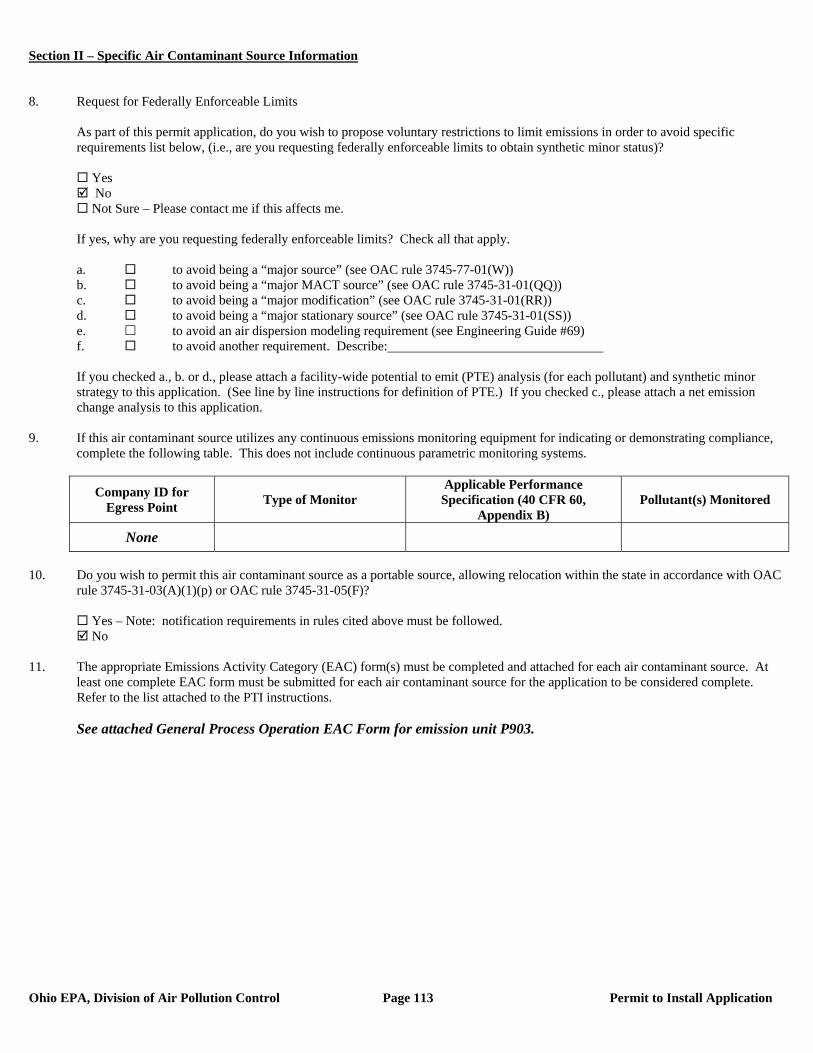
Section II – Specific Air Contaminant Source Information
Ohio EPA, Division of Air Pollution Control Page 113 Permit to Install Application
8. Request for Federally Enforceable Limits
As part of this permit application, do you wish to propose voluntary restrictions to limit emissions in order to avoid specific requirements list below, (i.e., are you requesting federally enforceable limits to obtain synthetic minor status)?
Yes No Not Sure – Please contact me if this affects me.
If yes, why are you requesting federally enforceable limits? Check all that apply. a. to avoid being a “major source” (see OAC rule 3745-77-01(W)) b. to avoid being a “major MACT source” (see OAC rule 3745-31-01(QQ)) c. to avoid being a “major modification” (see OAC rule 3745-31-01(RR)) d. to avoid being a “major stationary source” (see OAC rule 3745-31-01(SS)) e. to avoid an air dispersion modeling requirement (see Engineering Guide #69) f. to avoid another requirement. Describe: If you checked a., b. or d., please attach a facility-wide potential to emit (PTE) analysis (for each pollutant) and synthetic minor strategy to this application. (See line by line instructions for definition of PTE.) If you checked c., please attach a net emission change analysis to this application.
9. If this air contaminant source utilizes any continuous emissions monitoring equipment for indicating or demonstrating compliance, complete the following table. This does not include continuous parametric monitoring systems.
Company ID for Egress Point Type of Monitor
Applicable Performance Specification (40 CFR 60,
Appendix B) Pollutant(s) Monitored
None
10. Do you wish to permit this air contaminant source as a portable source, allowing relocation within the state in accordance with OAC
rule 3745-31-03(A)(1)(p) or OAC rule 3745-31-05(F)?
Yes – Note: notification requirements in rules cited above must be followed. No
11. The appropriate Emissions Activity Category (EAC) form(s) must be completed and attached for each air contaminant source. At
least one complete EAC form must be submitted for each air contaminant source for the application to be considered complete. Refer to the list attached to the PTI instructions. See attached General Process Operation EAC Form for emission unit P903.
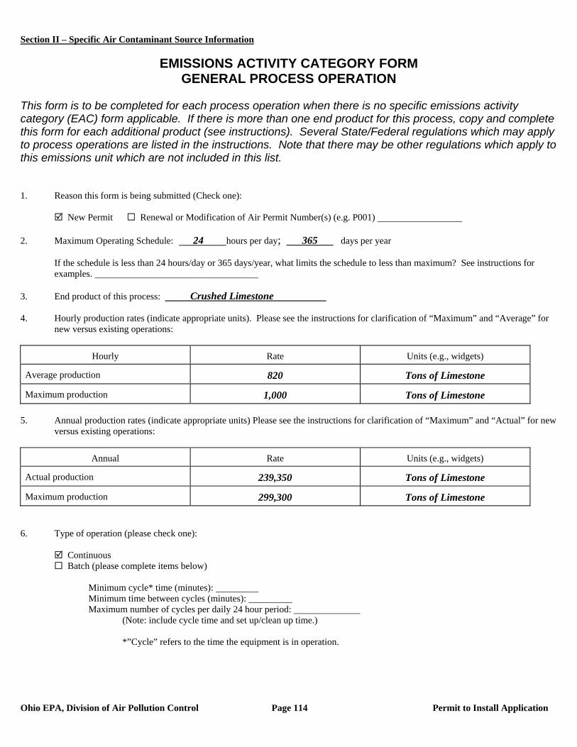
Section II – Specific Air Contaminant Source Information
Ohio EPA, Division of Air Pollution Control Page 114 Permit to Install Application
EMISSIONS ACTIVITY CATEGORY FORM
GENERAL PROCESS OPERATION This form is to be completed for each process operation when there is no specific emissions activity category (EAC) form applicable. If there is more than one end product for this process, copy and complete this form for each additional product (see instructions). Several State/Federal regulations which may apply to process operations are listed in the instructions. Note that there may be other regulations which apply to this emissions unit which are not included in this list. 1. Reason this form is being submitted (Check one): New Permit Renewal or Modification of Air Permit Number(s) (e.g. P001) 2. Maximum Operating Schedule: 24 hours per day; 365 days per year
If the schedule is less than 24 hours/day or 365 days/year, what limits the schedule to less than maximum? See instructions for examples.
3. End product of this process: Crushed Limestone 4. Hourly production rates (indicate appropriate units). Please see the instructions for clarification of “Maximum” and “Average” for
new versus existing operations:
Hourly Rate Units (e.g., widgets)
Average production 820 Tons of Limestone
Maximum production 1,000 Tons of Limestone 5. Annual production rates (indicate appropriate units) Please see the instructions for clarification of “Maximum” and “Actual” for new
versus existing operations:
Annual Rate Units (e.g., widgets)
Actual production 239,350 Tons of Limestone
Maximum production 299,300 Tons of Limestone 6. Type of operation (please check one):
Continuous Batch (please complete items below)
Minimum cycle* time (minutes): Minimum time between cycles (minutes): Maximum number of cycles per daily 24 hour period:
(Note: include cycle time and set up/clean up time.)
*”Cycle” refers to the time the equipment is in operation.
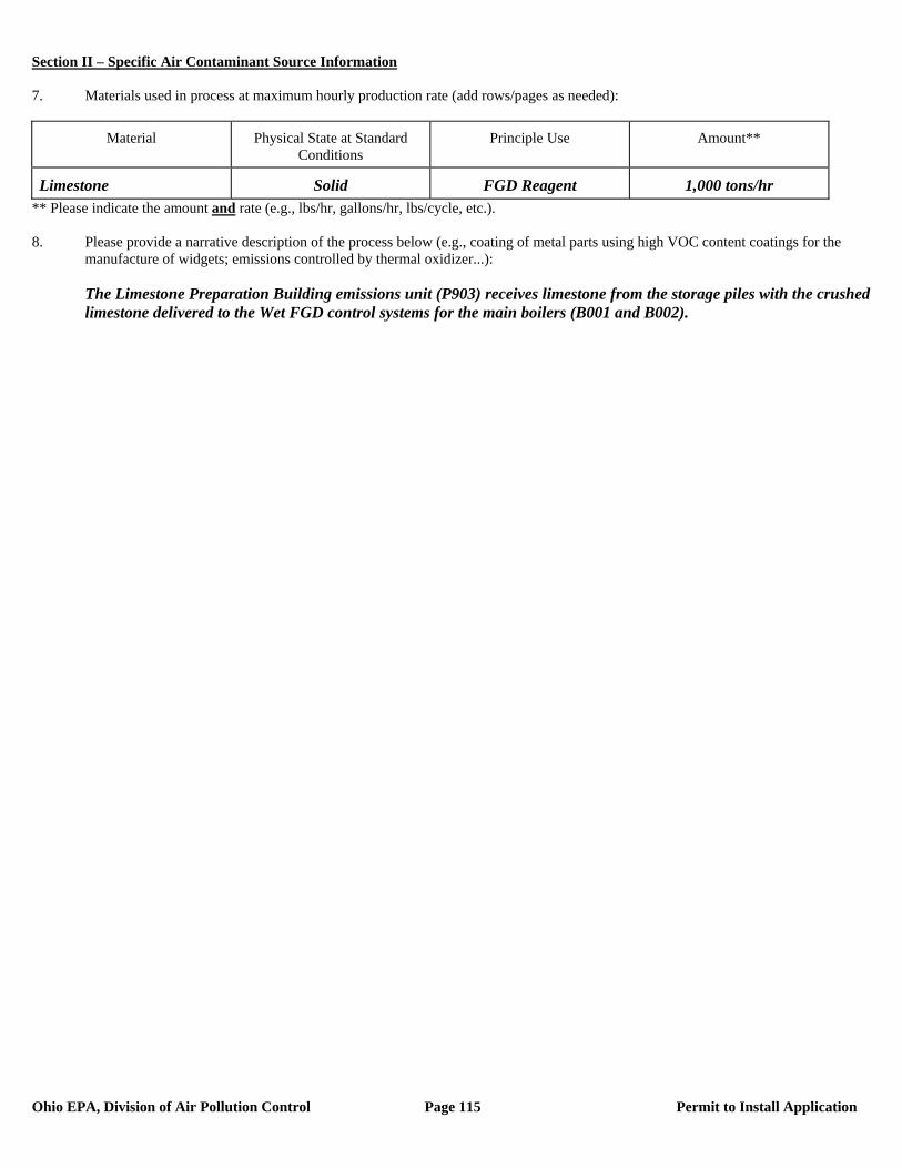
Section II – Specific Air Contaminant Source Information
Ohio EPA, Division of Air Pollution Control Page 115 Permit to Install Application
7. Materials used in process at maximum hourly production rate (add rows/pages as needed):
Material Physical State at Standard Conditions
Principle Use Amount**
Limestone Solid FGD Reagent 1,000 tons/hr ** Please indicate the amount and rate (e.g., lbs/hr, gallons/hr, lbs/cycle, etc.). 8. Please provide a narrative description of the process below (e.g., coating of metal parts using high VOC content coatings for the
manufacture of widgets; emissions controlled by thermal oxidizer...): The Limestone Preparation Building emissions unit (P903) receives limestone from the storage piles with the crushed
limestone delivered to the Wet FGD control systems for the main boilers (B001 and B002).
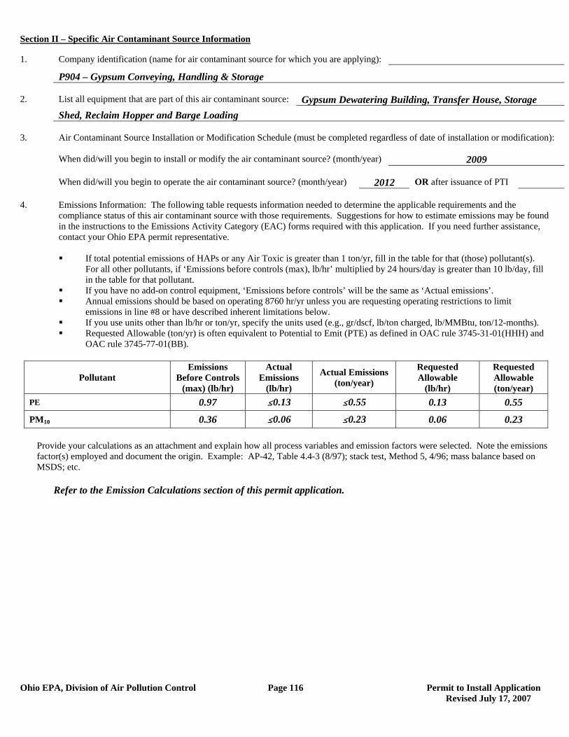
Section II – Specific Air Contaminant Source Information
Ohio EPA, Division of Air Pollution Control Page 116 Permit to Install Application Revised July 17, 2007
1. Company identification (name for air contaminant source for which you are applying):
P904 – Gypsum Conveying, Handling & Storage 2. List all equipment that are part of this air contaminant source: Gypsum Dewatering Building, Transfer House, Storage Shed, Reclaim Hopper and Barge Loading 3. Air Contaminant Source Installation or Modification Schedule (must be completed regardless of date of installation or modification): When did/will you begin to install or modify the air contaminant source? (month/year) 2009 When did/will you begin to operate the air contaminant source? (month/year) 2012 OR after issuance of PTI 4. Emissions Information: The following table requests information needed to determine the applicable requirements and the compliance status of this air contaminant source with those requirements. Suggestions for how to estimate emissions may be found in the instructions to the Emissions Activity Category (EAC) forms required with this application. If you need further assistance, contact your Ohio EPA permit representative.
If total potential emissions of HAPs or any Air Toxic is greater than 1 ton/yr, fill in the table for that (those) pollutant(s).
For all other pollutants, if ‘Emissions before controls (max), lb/hr’ multiplied by 24 hours/day is greater than 10 lb/day, fill in the table for that pollutant.
If you have no add-on control equipment, ‘Emissions before controls’ will be the same as ‘Actual emissions’. Annual emissions should be based on operating 8760 hr/yr unless you are requesting operating restrictions to limit
emissions in line #8 or have described inherent limitations below. If you use units other than lb/hr or ton/yr, specify the units used (e.g., gr/dscf, lb/ton charged, lb/MMBtu, ton/12-months). Requested Allowable (ton/yr) is often equivalent to Potential to Emit (PTE) as defined in OAC rule 3745-31-01(HHH) and
OAC rule 3745-77-01(BB).
Pollutant Emissions
Before Controls (max) (lb/hr)
Actual Emissions
(lb/hr)
Actual Emissions (ton/year)
Requested Allowable
(lb/hr)
Requested Allowable (ton/year)
PE 0.97 #0.13 #0.55 0.13 0.55
PM10 0.36 #0.06 #0.23 0.06 0.23
Provide your calculations as an attachment and explain how all process variables and emission factors were selected. Note the emissions factor(s) employed and document the origin. Example: AP-42, Table 4.4-3 (8/97); stack test, Method 5, 4/96; mass balance based on MSDS; etc.
Refer to the Emission Calculations section of this permit application.
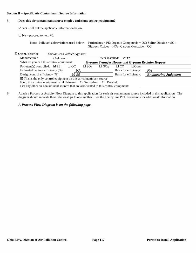
Section II – Specific Air Contaminant Source Information
Ohio EPA, Division of Air Pollution Control Page 117 Permit to Install Application
5. Does this air contaminant source employ emissions control equipment? Yes – fill out the applicable information below. No – proceed to item #6. Note: Pollutant abbreviations used below: Particulates = PE; Organic Compounds = OC; Sulfur Dioxide = SO2; Nitrogen Oxides = NOX; Carbon Monoxide = CO
Other, describe Enclosures w/Wet Gypsum Manufacturer: Unknown Year installed: 2012 What do you call this control equipment: Gypsum Transfer House and Gypsum Reclaim Hopper Pollutant(s) controlled: PE OC SO2 NOX CO Other Estimated capture efficiency (%) NA Basis for efficiency: NA Design control efficiency (%) 90-95 Basis for efficiency: Engineering Judgment This is the only control equipment on this air contaminant source If no, this control equipment is: Primary Secondary Parallel List any other air contaminant sources that are also vented to this control equipment:
6. Attach a Process or Activity Flow Diagram to this application for each air contaminant source included in this application. The
diagram should indicate their relationships to one another. See the line by line PTI instructions for additional information. A Process Flow Diagram is on the following page.
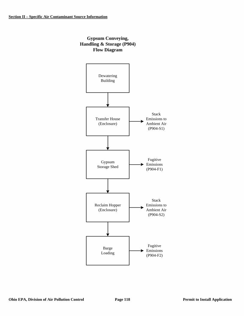
Section II – Specific Air Contaminant Source Information
Ohio EPA, Division of Air Pollution Control Page 118 Permit to Install Application
DewateringBuilding
Transfer House(Enclosure)
GypsumStorage Shed
Reclaim Hopper(Enclosure)
BargeLoading
Gypsum Conveying, Handling & Storage (P904)
Flow Diagram
Stack Emissions to Ambient Air(P904-S1)
Stack Emissions to Ambient Air (P904-S2)
Fugitive Emissions (P904-F1)
Fugitive Emissions (P904-F2)

Section II – Specific Air Contaminant Source Information
Ohio EPA, Division of Air Pollution Control Page 119 Permit to Install Application
7. Emissions egress point(s) information: PTIs which allow total emissions in excess of the thresholds listed below will be subject to an
air quality modeling analysis. This analysis is to assure that the impact from the requested project will not exceed Ohio’s Acceptable Incremental Impacts for criteria pollutants and/or Maximum Allowable Ground Level Concentrations (MAGLC) for air toxics. Permit requests that would have unacceptable impacts can not be approved as proposed. See the line by line PTI instructions for additional information.
Complete the tables below if the requested allowable annual emission rate for this PTI exceeds any of the following:
Particulate Matter (PM10): 10 tons per year Sulfur Dioxide (SO2): 25 tons per year Nitrogen Oxides (NOX): 25 tons per year Carbon Monoxide (CO): 100 tons per year Air Toxic: 1 ton per year. An air toxic is any air pollutant for which the American Council of Governmental Industrial
Hygienists (ACGIH) has established a Threshold Limit Value (TLV).
Complete Table 7-A below for each stack emissions egress point. An egress point is a point at which emissions from an air contaminant source are released into the ambient (outside) air. List each individual egress point on a separate line.
(1) Note: The total annual PM10 emissions from the Gypsum Conveying, Handling & Storage (P904) operation are less than 1.0 ton. As a result, this emissions unit was not included in the air quality modeling submitted with this PTI application.
*Type codes for stack egress points:
A. vertical stack (unobstructed): There are no obstructions to upward flow in or on the stack such as a rain cap. B. vertical stack (obstructed): There are obstructions to the upward flow, such as a rain cap, which prevents or
inhibits the air flow in a vertical direction. C. non-vertical stack: The stack directs the air flow in a direction which is not directly upward.
Complete Table 7-B below for each fugitive emissions egress point. List each individual egress point on a separate line. Refer to the description of the fugitive egress point type codes below the table for use in completing the type code column of the table. For air contaminant sources like roadways and storage piles, only the first 5 columns need to be completed. For an air contaminant source with multiple fugitive emissions egress points, include only the primary egress points.
Table 7-B, Fugitive Egress Point Information
Company ID for the Egress Point (examples: Garage Door B, Building
C, Roof Monitor; etc.)
Type Code*
Egress Point Description (examples: garage door, 12X30 feet, west wall; outside gravel storage piles;
etc.
Fugitive Egress Point Height from
the Ground (ft)
Minimum Distance to
the Property Line (ft)
Exit Gas Temp.
(F)
NA NA NA NA NA NA
*Type codes for fugitive egress point:
D. door or window E. other opening in the building without a duct F. no stack and no building enclosing the air contaminant source (e.g., roadways)
Table 7-A, Stack Egress Point Information
Company Name or ID for the Egress Point (examples: Stack A;
Boiler Stack; etc.)
Type Code*
Stack Egress Point Shape and Dimensions (in) (examples:
round 10 inch ID; rectangular 14 X 16 inches; etc.)
Stack Egress Point Height
from the Ground (ft)
Stack Temp. at
Max. Capacity
(F)
Stack Flow Rate at Max.
Capacity (ACFM)
Minimum Distance to
the Property Line (ft)
NA(1) NA NA NA NA NA NA
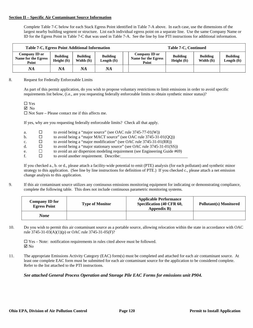
Section II – Specific Air Contaminant Source Information
Ohio EPA, Division of Air Pollution Control Page 120 Permit to Install Application
Complete Table 7-C below for each Stack Egress Point identified in Table 7-A above. In each case, use the dimensions of the largest nearby building segment or structure. List each individual egress point on a separate line. Use the same Company Name or ID for the Egress Point in Table 7-C that was used in Table 7-A. See the line by line PTI instructions for additional information.
Table 7-C, Egress Point Additional Information Table 7-C, Continued
Company ID or Name for the Egress
Point
Building Height (ft)
Building Width (ft)
Building Length (ft)
Company ID or Name for the Egress
Point
Building Height (ft)
Building Width (ft)
Building Length (ft)
NA NA NA NA 8. Request for Federally Enforceable Limits
As part of this permit application, do you wish to propose voluntary restrictions to limit emissions in order to avoid specific requirements list below, (i.e., are you requesting federally enforceable limits to obtain synthetic minor status)?
Yes No Not Sure – Please contact me if this affects me.
If yes, why are you requesting federally enforceable limits? Check all that apply. a. to avoid being a “major source” (see OAC rule 3745-77-01(W)) b. to avoid being a “major MACT source” (see OAC rule 3745-31-01(QQ)) c. to avoid being a “major modification” (see OAC rule 3745-31-01(RR)) d. to avoid being a “major stationary source” (see OAC rule 3745-31-01(SS)) e. to avoid an air dispersion modeling requirement (see Engineering Guide #69) f. to avoid another requirement. Describe: If you checked a., b. or d., please attach a facility-wide potential to emit (PTE) analysis (for each pollutant) and synthetic minor strategy to this application. (See line by line instructions for definition of PTE.) If you checked c., please attach a net emission change analysis to this application.
9. If this air contaminant source utilizes any continuous emissions monitoring equipment for indicating or demonstrating compliance, complete the following table. This does not include continuous parametric monitoring systems.
Company ID for Egress Point Type of Monitor
Applicable Performance Specification (40 CFR 60,
Appendix B) Pollutant(s) Monitored
None
10. Do you wish to permit this air contaminant source as a portable source, allowing relocation within the state in accordance with OAC
rule 3745-31-03(A)(1)(p) or OAC rule 3745-31-05(F)?
Yes – Note: notification requirements in rules cited above must be followed. No
11. The appropriate Emissions Activity Category (EAC) form(s) must be completed and attached for each air contaminant source. At
least one complete EAC form must be submitted for each air contaminant source for the application to be considered complete. Refer to the list attached to the PTI instructions. See attached General Process Operation and Storage Pile EAC Forms for emissions unit P904.
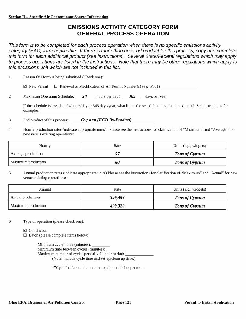
Section II – Specific Air Contaminant Source Information
Ohio EPA, Division of Air Pollution Control Page 121 Permit to Install Application
EMISSIONS ACTIVITY CATEGORY FORM
GENERAL PROCESS OPERATION This form is to be completed for each process operation when there is no specific emissions activity category (EAC) form applicable. If there is more than one end product for this process, copy and complete this form for each additional product (see instructions). Several State/Federal regulations which may apply to process operations are listed in the instructions. Note that there may be other regulations which apply to this emissions unit which are not included in this list. 1. Reason this form is being submitted (Check one): New Permit Renewal or Modification of Air Permit Number(s) (e.g. P001) 2. Maximum Operating Schedule: 24 hours per day; 365 days per year
If the schedule is less than 24 hours/day or 365 days/year, what limits the schedule to less than maximum? See instructions for examples.
3. End product of this process: Gypsum (FGD By-Product) 4. Hourly production rates (indicate appropriate units). Please see the instructions for clarification of “Maximum” and “Average” for
new versus existing operations:
Hourly Rate Units (e.g., widgets)
Average production 57 Tons of Gypsum
Maximum production 60 Tons of Gypsum 5. Annual production rates (indicate appropriate units) Please see the instructions for clarification of “Maximum” and “Actual” for new
versus existing operations:
Annual Rate Units (e.g., widgets)
Actual production 399,456 Tons of Gypsum
Maximum production 499,320 Tons of Gypsum 6. Type of operation (please check one):
Continuous Batch (please complete items below)
Minimum cycle* time (minutes): Minimum time between cycles (minutes): Maximum number of cycles per daily 24 hour period:
(Note: include cycle time and set up/clean up time.)
*”Cycle” refers to the time the equipment is in operation.
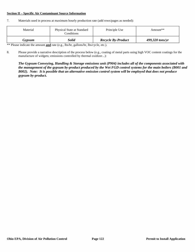
Section II – Specific Air Contaminant Source Information
Ohio EPA, Division of Air Pollution Control Page 122 Permit to Install Application
7. Materials used in process at maximum hourly production rate (add rows/pages as needed):
Material Physical State at Standard Conditions
Principle Use Amount**
Gypsum Solid Recycle By-Product 499,320 tons/yr ** Please indicate the amount and rate (e.g., lbs/hr, gallons/hr, lbs/cycle, etc.). 8. Please provide a narrative description of the process below (e.g., coating of metal parts using high VOC content coatings for the
manufacture of widgets; emissions controlled by thermal oxidizer...): The Gypsum Conveying, Handling & Storage emissions unit (P904) includes all of the components associated with
the management of the gypsum by-product produced by the Wet FGD control systems for the main boilers (B001 and B002). Note: It is possible that an alternative emission control system will be employed that does not produce gypsum by-product.
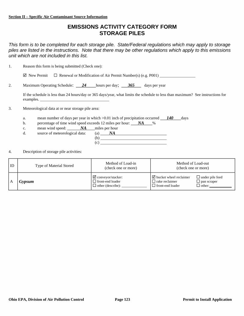
Section II – Specific Air Contaminant Source Information
Ohio EPA, Division of Air Pollution Control Page 123 Permit to Install Application
EMISSIONS ACTIVITY CATEGORY FORM
STORAGE PILES This form is to be completed for each storage pile. State/Federal regulations which may apply to storage piles are listed in the instructions. Note that there may be other regulations which apply to this emissions unit which are not included in this list. 1. Reason this form is being submitted (Check one): New Permit Renewal or Modification of Air Permit Number(s) (e.g. P001) 2. Maximum Operating Schedule: 24 hours per day; 365 days per year
If the schedule is less than 24 hours/day or 365 days/year, what limits the schedule to less than maximum? See instructions for examples.
3. Meteorological data at or near storage pile area:
a. mean number of days per year in which >0.01 inch of precipitation occurred 140 days b. percentage of time wind speed exceeds 12 miles per hour: NA % c. mean wind speed: NA miles per hour d. source of meteorological data: (a) NA
(b) (c)
4. Description of storage pile activities:
ID Type of Material Stored Method of Load-in (check one or more)
Method of Load-out (check one or more)
A Gypsum conveyor/stacker: front-end loader other (describe): ______________
bucket wheel reclaimer under pile feed rake reclaimer pan scraper front-end loader other: ____________
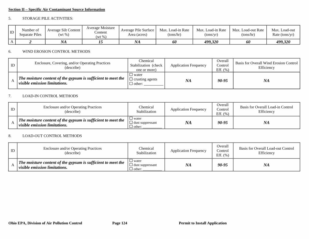
Section II – Specific Air Contaminant Source Information
Ohio EPA, Division of Air Pollution Control Page 124 Permit to Install Application
5. STORAGE PILE ACTIVITIES:
ID Number of Separate Piles
Average Silt Content (wt %)
Average Moisture Content (wt %)
Average Pile Surface Area (acres)
Max. Load-in Rate (tons/hr)
Max. Load-in Rate (tons/yr)
Max. Load-out Rate (tons/hr)
Max. Load-out Rate (tons/yr)
A 2 NA 15 NA 60 499,320 60 499,320 6. WIND EROSION CONTROL METHODS
ID Enclosure, Covering, and/or Operating Practices (describe)
Chemical Stabilization (check
one or more) Application Frequency
Overall Control Eff. (%)
Basis for Overall Wind Erosion Control Efficiency
A The moisture content of the gypsum is sufficient to meet the visible emission limitations.
water crusting agents other: __________
NA 90-95 NA
7. LOAD-IN CONTROL METHODS
ID Enclosure and/or Operating Practices (describe)
Chemical Stabilization Application Frequency
Overall Control Eff. (%)
Basis for Overall Load-in Control Efficiency
A The moisture content of the gypsum is sufficient to meet the visible emission limitations.
water dust suppressant other: ___________
NA 90-95 NA
8. LOAD-OUT CONTROL METHODS
ID Enclosure and/or Operating Practices (describe)
Chemical Stabilization Application Frequency
Overall Control Eff. (%)
Basis for Overall Load-out Control Efficiency
A The moisture content of the gypsum is sufficient to meet the visible emission limitations.
water dust suppressant other: ___________
NA 90-95 NA
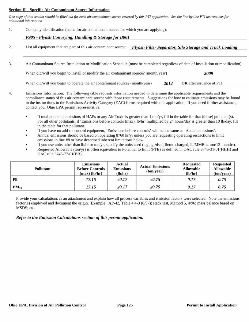
Section II – Specific Air Contaminant Source Information
Ohio EPA, Division of Air Pollution Control Page 125 Permit to Install Application
One copy of this section should be filled out for each air contaminant source covered by this PTI application. See the line by line PTI instructions for additional information. 1. Company identification (name for air contaminant source for which you are applying):
P905 - Flyash Conveying, Handling & Storage for B001 2. List all equipment that are part of this air contaminant source: Flyash Filter Separator, Silo Storage and Truck Loading 3. Air Contaminant Source Installation or Modification Schedule (must be completed regardless of date of installation or modification): When did/will you begin to install or modify the air contaminant source? (month/year) 2009 When did/will you begin to operate the air contaminant source? (month/year) 2012 OR after issuance of PTI 4. Emissions Information: The following table requests information needed to determine the applicable requirements and the compliance status of this air contaminant source with those requirements. Suggestions for how to estimate emissions may be found in the instructions to the Emissions Activity Category (EAC) forms required with this application. If you need further assistance, contact your Ohio EPA permit representative.
If total potential emissions of HAPs or any Air Toxic is greater than 1 ton/yr, fill in the table for that (those) pollutant(s).
For all other pollutants, if ‘Emissions before controls (max), lb/hr’ multiplied by 24 hours/day is greater than 10 lb/day, fill in the table for that pollutant.
If you have no add-on control equipment, ‘Emissions before controls’ will be the same as ‘Actual emissions’. Annual emissions should be based on operating 8760 hr/yr unless you are requesting operating restrictions to limit
emissions in line #8 or have described inherent limitations below. If you use units other than lb/hr or ton/yr, specify the units used (e.g., gr/dscf, lb/ton charged, lb/MMBtu, ton/12-months). Requested Allowable (ton/yr) is often equivalent to Potential to Emit (PTE) as defined in OAC rule 3745-31-01(HHH) and
OAC rule 3745-77-01(BB).
Pollutant Emissions
Before Controls (max) (lb/hr)
Actual Emissions
(lb/hr)
Actual Emissions (ton/year)
Requested Allowable
(lb/hr)
Requested Allowable (ton/year)
PE 17.15 #0.17 #0.75 0.17 0.75
PM10 17.15 #0.17 #0.75 0.17 0.75
Provide your calculations as an attachment and explain how all process variables and emission factors were selected. Note the emissions factor(s) employed and document the origin. Example: AP-42, Table 4.4-3 (8/97); stack test, Method 5, 4/96; mass balance based on MSDS; etc. Refer to the Emission Calculations section of this permit application.
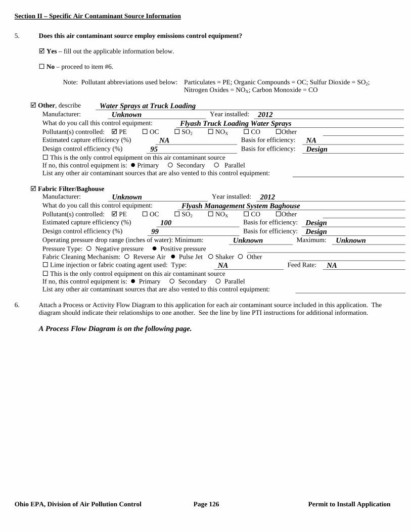
Section II – Specific Air Contaminant Source Information
Ohio EPA, Division of Air Pollution Control Page 126 Permit to Install Application
5. Does this air contaminant source employ emissions control equipment? Yes – fill out the applicable information below. No – proceed to item #6. Note: Pollutant abbreviations used below: Particulates = PE; Organic Compounds = OC; Sulfur Dioxide = SO2; Nitrogen Oxides = NOX; Carbon Monoxide = CO
Other, describe Water Sprays at Truck Loading Manufacturer: Unknown Year installed: 2012 What do you call this control equipment: Flyash Truck Loading Water Sprays Pollutant(s) controlled: PE OC SO2 NOX CO Other Estimated capture efficiency (%) NA Basis for efficiency: NA Design control efficiency (%) 95 Basis for efficiency: Design This is the only control equipment on this air contaminant source If no, this control equipment is: Primary Secondary Parallel List any other air contaminant sources that are also vented to this control equipment:
Fabric Filter/Baghouse
Manufacturer: Unknown Year installed: 2012 What do you call this control equipment: Flyash Management System Baghouse Pollutant(s) controlled: PE OC SO2 NOX CO Other Estimated capture efficiency (%) 100 Basis for efficiency: Design Design control efficiency (%) 99 Basis for efficiency: Design Operating pressure drop range (inches of water): Minimum: Unknown Maximum: Unknown Pressure Type: Negative pressure Positive pressure Fabric Cleaning Mechanism: Reverse Air Pulse Jet Shaker Other Lime injection or fabric coating agent used: Type: NA Feed Rate: NA This is the only control equipment on this air contaminant source If no, this control equipment is: Primary Secondary Parallel List any other air contaminant sources that are also vented to this control equipment:
6. Attach a Process or Activity Flow Diagram to this application for each air contaminant source included in this application. The
diagram should indicate their relationships to one another. See the line by line PTI instructions for additional information. A Process Flow Diagram is on the following page.

Section II – Specific Air Contaminant Source Information
Ohio EPA, Division of Air Pollution Control Page 127 Permit to Install Application

Section II – Specific Air Contaminant Source Information
Ohio EPA, Division of Air Pollution Control Page 128 Permit to Install Application
7. Emissions egress point(s) information: PTIs which allow total emissions in excess of the thresholds listed below will be subject to an
air quality modeling analysis. This analysis is to assure that the impact from the requested project will not exceed Ohio’s Acceptable Incremental Impacts for criteria pollutants and/or Maximum Allowable Ground Level Concentrations (MAGLC) for air toxics.
Permit requests that would have unacceptable impacts can not be approved as proposed. See the line by line PTI instructions for additional information.
Complete the tables below if the requested allowable annual emission rate for this PTI exceeds any of the following:
Particulate Matter (PM10): 10 tons per year Sulfur Dioxide (SO2): 25 tons per year Nitrogen Oxides (NOX): 25 tons per year Carbon Monoxide (CO): 100 tons per year Air Toxic: 1 ton per year. An air toxic is any air pollutant for which the American Council of Governmental Industrial
Hygienists (ACGIH) has established a Threshold Limit Value (TLV).
Complete Table 7-A below for each stack emissions egress point. An egress point is a point at which emissions from an air contaminant source are released into the ambient (outside) air. List each individual egress point on a separate line.
(1) Note: The total annual PM10 emissions from the Flyash Conveying, Handling & Storage (P905) operation are less than 1.0 ton. As a result, this emissions unit was not included in the air quality modeling submitted with this PTI application.
*Type codes for stack egress points:
A. vertical stack (unobstructed): There are no obstructions to upward flow in or on the stack such as a rain cap. B. vertical stack (obstructed): There are obstructions to the upward flow, such as a rain cap, which prevents or
inhibits the air flow in a vertical direction. C. non-vertical stack: The stack directs the air flow in a direction which is not directly upward.
Complete Table 7-B below for each fugitive emissions egress point. List each individual egress point on a separate line. Refer to the description of the fugitive egress point type codes below the table for use in completing the type code column of the table. For air contaminant sources like roadways and storage piles, only the first 5 columns need to be completed. For an air contaminant source with multiple fugitive emissions egress points, include only the primary egress points.
Table 7-B, Fugitive Egress Point Information
Company ID for the Egress Point (examples: Garage Door B, Building
C, Roof Monitor; etc.)
Type Code*
Egress Point Description (examples: garage door, 12X30 feet, west wall; outside gravel storage piles; etc.
Fugitive Egress Point Height
from the Ground (ft)
Minimum Distance to
the Property Line (ft)
Exit Gas Temp.
(F)
NA NA NA NA NA NA
*Type codes for fugitive egress point:
D. door or window E. other opening in the building without a duct F. no stack and no building enclosing the air contaminant source (e.g., roadways)
Table 7-A, Stack Egress Point Information
Company Name or ID for the Egress Point (examples: Stack A;
Boiler Stack; etc.)
Type Code*
Stack Egress Point Shape and Dimensions (in) (examples:
round 10 inch ID; rectangular 14 X 16 inches; etc.)
Stack Egress Point Height
from the Ground (ft)
Stack Temp. at
Max. Capacity
(F)
Stack Flow Rate at Max.
Capacity (ACFM)
Minimum Distance to
the Property Line (ft)
NA(1) NA NA NA NA NA NA
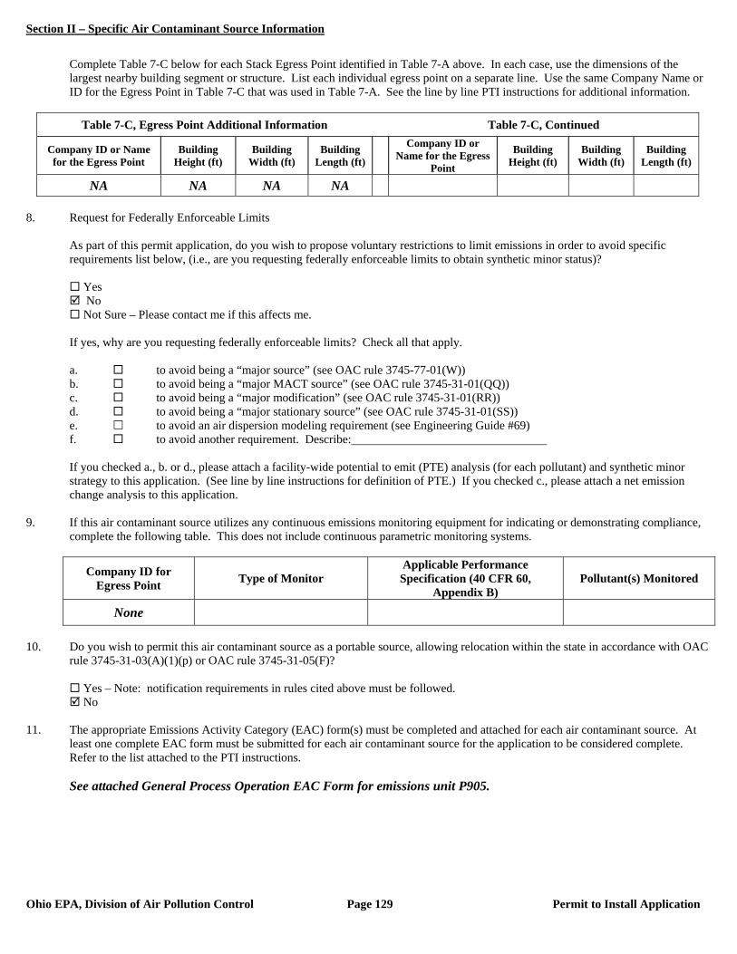
Section II – Specific Air Contaminant Source Information
Ohio EPA, Division of Air Pollution Control Page 129 Permit to Install Application
Complete Table 7-C below for each Stack Egress Point identified in Table 7-A above. In each case, use the dimensions of the largest nearby building segment or structure. List each individual egress point on a separate line. Use the same Company Name or ID for the Egress Point in Table 7-C that was used in Table 7-A. See the line by line PTI instructions for additional information.
Table 7-C, Egress Point Additional Information Table 7-C, Continued
Company ID or Name for the Egress Point
Building Height (ft)
Building Width (ft)
Building Length (ft)
Company ID or Name for the Egress
Point
Building Height (ft)
Building Width (ft)
Building Length (ft)
NA NA NA NA 8. Request for Federally Enforceable Limits
As part of this permit application, do you wish to propose voluntary restrictions to limit emissions in order to avoid specific requirements list below, (i.e., are you requesting federally enforceable limits to obtain synthetic minor status)?
Yes No Not Sure – Please contact me if this affects me.
If yes, why are you requesting federally enforceable limits? Check all that apply. a. to avoid being a “major source” (see OAC rule 3745-77-01(W)) b. to avoid being a “major MACT source” (see OAC rule 3745-31-01(QQ)) c. to avoid being a “major modification” (see OAC rule 3745-31-01(RR)) d. to avoid being a “major stationary source” (see OAC rule 3745-31-01(SS)) e. to avoid an air dispersion modeling requirement (see Engineering Guide #69) f. to avoid another requirement. Describe: If you checked a., b. or d., please attach a facility-wide potential to emit (PTE) analysis (for each pollutant) and synthetic minor strategy to this application. (See line by line instructions for definition of PTE.) If you checked c., please attach a net emission change analysis to this application.
9. If this air contaminant source utilizes any continuous emissions monitoring equipment for indicating or demonstrating compliance, complete the following table. This does not include continuous parametric monitoring systems.
Company ID for Egress Point Type of Monitor
Applicable Performance Specification (40 CFR 60,
Appendix B) Pollutant(s) Monitored
None
10. Do you wish to permit this air contaminant source as a portable source, allowing relocation within the state in accordance with OAC
rule 3745-31-03(A)(1)(p) or OAC rule 3745-31-05(F)?
Yes – Note: notification requirements in rules cited above must be followed. No
11. The appropriate Emissions Activity Category (EAC) form(s) must be completed and attached for each air contaminant source. At
least one complete EAC form must be submitted for each air contaminant source for the application to be considered complete. Refer to the list attached to the PTI instructions. See attached General Process Operation EAC Form for emissions unit P905.
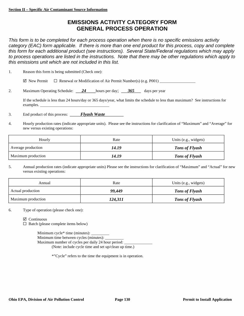
Section II – Specific Air Contaminant Source Information
Ohio EPA, Division of Air Pollution Control Page 130 Permit to Install Application
EMISSIONS ACTIVITY CATEGORY FORM
GENERAL PROCESS OPERATION This form is to be completed for each process operation when there is no specific emissions activity category (EAC) form applicable. If there is more than one end product for this process, copy and complete this form for each additional product (see instructions). Several State/Federal regulations which may apply to process operations are listed in the instructions. Note that there may be other regulations which apply to this emissions unit which are not included in this list. 1. Reason this form is being submitted (Check one): New Permit Renewal or Modification of Air Permit Number(s) (e.g. P001) 2. Maximum Operating Schedule: 24 hours per day; 365 days per year
If the schedule is less than 24 hours/day or 365 days/year, what limits the schedule to less than maximum? See instructions for examples.
3. End product of this process: Flyash Waste 4. Hourly production rates (indicate appropriate units). Please see the instructions for clarification of “Maximum” and “Average” for
new versus existing operations:
Hourly Rate Units (e.g., widgets)
Average production 14.19 Tons of Flyash
Maximum production 14.19 Tons of Flyash 5. Annual production rates (indicate appropriate units) Please see the instructions for clarification of “Maximum” and “Actual” for new
versus existing operations:
Annual Rate Units (e.g., widgets)
Actual production 99,449 Tons of Flyash
Maximum production 124,311 Tons of Flyash 6. Type of operation (please check one):
Continuous Batch (please complete items below)
Minimum cycle* time (minutes): Minimum time between cycles (minutes): Maximum number of cycles per daily 24 hour period:
(Note: include cycle time and set up/clean up time.)
*”Cycle” refers to the time the equipment is in operation.

Section II – Specific Air Contaminant Source Information
Ohio EPA, Division of Air Pollution Control Page 131 Permit to Install Application
7. Materials used in process at maximum hourly production rate (add rows/pages as needed):
Material Physical State at Standard Conditions
Principle Use Amount**
Flyash Solid Waste Material 124,311 tons/yr ** Please indicate the amount and rate (e.g., lbs/hr, gallons/hr, lbs/cycle, etc.). 8. Please provide a narrative description of the process below (e.g., coating of metal parts using high VOC content coatings for the
manufacture of widgets; emissions controlled by thermal oxidizer...): The Flyash Conveying, Handling & Storage emissions unit (P905) includes all of the components associated with the
management of flyash produced by the baghouse control systems for main boiler B001.

Section II – Specific Air Contaminant Source Information
Ohio EPA, Division of Air Pollution Control Page 132 Permit to Install Application
One copy of this section should be filled out for each air contaminant source covered by this PTI application. See the line by line PTI instructions for additional information. 1. Company identification (name for air contaminant source for which you are applying):
P906 - Flyash Conveying, Handling & Storage for B002 2. List all equipment that are part of this air contaminant source: Flyash Filter Separator, Silo Storage and Truck Loading 3. Air Contaminant Source Installation or Modification Schedule (must be completed regardless of date of installation or modification): When did/will you begin to install or modify the air contaminant source? (month/year) 2009 When did/will you begin to operate the air contaminant source? (month/year) 2012 OR after issuance of PTI 4. Emissions Information: The following table requests information needed to determine the applicable requirements and the compliance status of this air contaminant source with those requirements. Suggestions for how to estimate emissions may be found in the instructions to the Emissions Activity Category (EAC) forms required with this application. If you need further assistance, contact your Ohio EPA permit representative.
If total potential emissions of HAPs or any Air Toxic is greater than 1 ton/yr, fill in the table for that (those) pollutant(s).
For all other pollutants, if ‘Emissions before controls (max), lb/hr’ multiplied by 24 hours/day is greater than 10 lb/day, fill in the table for that pollutant.
If you have no add-on control equipment, ‘Emissions before controls’ will be the same as ‘Actual emissions’. Annual emissions should be based on operating 8760 hr/yr unless you are requesting operating restrictions to limit
emissions in line #8 or have described inherent limitations below. If you use units other than lb/hr or ton/yr, specify the units used (e.g., gr/dscf, lb/ton charged, lb/MMBtu, ton/12-months). Requested Allowable (ton/yr) is often equivalent to Potential to Emit (PTE) as defined in OAC rule 3745-31-01(HHH) and
OAC rule 3745-77-01(BB).
Pollutant Emissions
Before Controls (max) (lb/hr)
Actual Emissions
(lb/hr)
Actual Emissions (ton/year)
Requested Allowable
(lb/hr)
Requested Allowable (ton/year)
PE 17.15 #0.17 #0.75 0.17 0.75
PM10 17.15 #0.17 #0.75 0.17 0.75
Provide your calculations as an attachment and explain how all process variables and emission factors were selected. Note the emissions factor(s) employed and document the origin. Example: AP-42, Table 4.4-3 (8/97); stack test, Method 5, 4/96; mass balance based on MSDS; etc. Refer to the Emission Calculations section of this permit application.

Section II – Specific Air Contaminant Source Information
Ohio EPA, Division of Air Pollution Control Page 133 Permit to Install Application
5. Does this air contaminant source employ emissions control equipment? Yes – fill out the applicable information below. No – proceed to item #6. Note: Pollutant abbreviations used below: Particulates = PE; Organic Compounds = OC; Sulfur Dioxide = SO2; Nitrogen Oxides = NOX; Carbon Monoxide = CO
Other, describe Water Sprays at Truck Loading Manufacturer: Unknown Year installed: 2012 What do you call this control equipment: Flyash Truck Loading Water Sprays Pollutant(s) controlled: PE OC SO2 NOX CO Other Estimated capture efficiency (%) NA Basis for efficiency: NA Design control efficiency (%) 95 Basis for efficiency: Design This is the only control equipment on this air contaminant source If no, this control equipment is: Primary Secondary Parallel List any other air contaminant sources that are also vented to this control equipment:
Fabric Filter/Baghouse
Manufacturer: Unknown Year installed: 2012 What do you call this control equipment: Flyash Management System Baghouse Pollutant(s) controlled: PE OC SO2 NOX CO Other Estimated capture efficiency (%) 100 Basis for efficiency: Design Design control efficiency (%) 99 Basis for efficiency: Design Operating pressure drop range (inches of water): Minimum: Unknown Maximum: Unknown Pressure Type: Negative pressure Positive pressure Fabric Cleaning Mechanism: Reverse Air Pulse Jet Shaker Other Lime injection or fabric coating agent used: Type: NA Feed Rate: NA This is the only control equipment on this air contaminant source If no, this control equipment is: Primary Secondary Parallel List any other air contaminant sources that are also vented to this control equipment:
6. Attach a Process or Activity Flow Diagram to this application for each air contaminant source included in this application. The
diagram should indicate their relationships to one another. See the line by line PTI instructions for additional information. A Process Flow Diagram is on the following page.
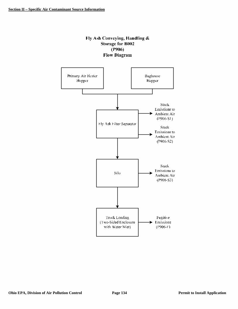
Section II – Specific Air Contaminant Source Information
Ohio EPA, Division of Air Pollution Control Page 134 Permit to Install Application
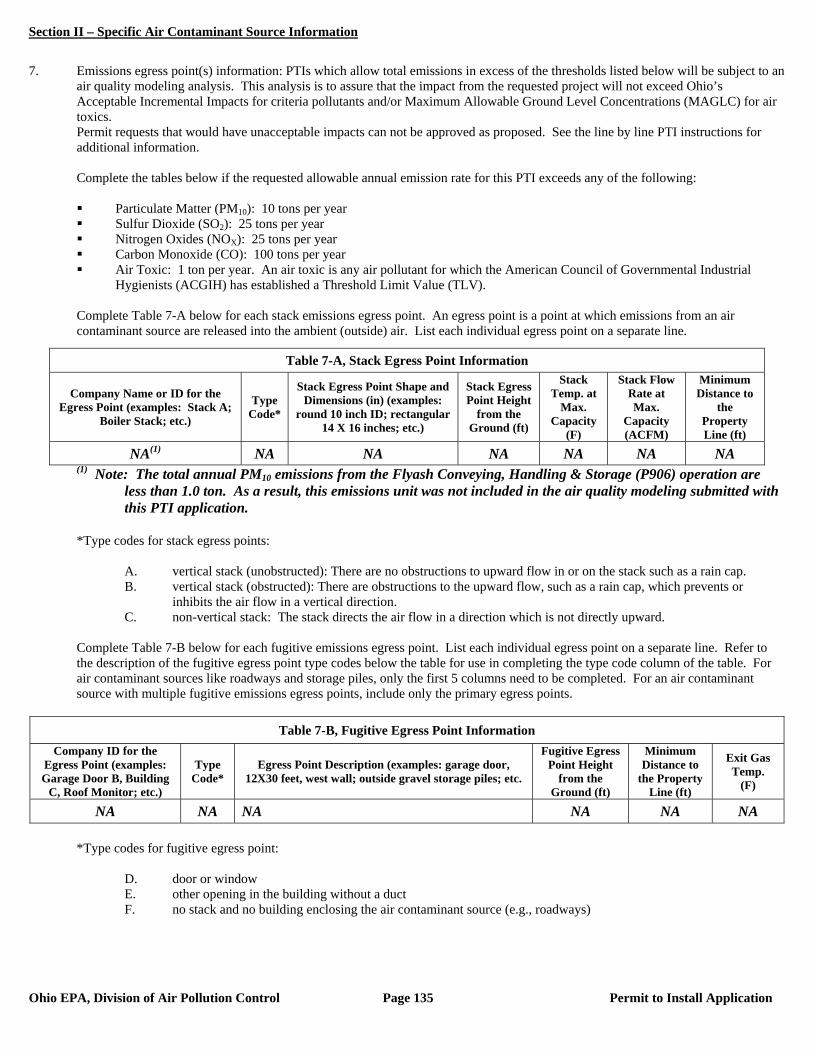
Section II – Specific Air Contaminant Source Information
Ohio EPA, Division of Air Pollution Control Page 135 Permit to Install Application
7. Emissions egress point(s) information: PTIs which allow total emissions in excess of the thresholds listed below will be subject to an
air quality modeling analysis. This analysis is to assure that the impact from the requested project will not exceed Ohio’s Acceptable Incremental Impacts for criteria pollutants and/or Maximum Allowable Ground Level Concentrations (MAGLC) for air toxics.
Permit requests that would have unacceptable impacts can not be approved as proposed. See the line by line PTI instructions for additional information.
Complete the tables below if the requested allowable annual emission rate for this PTI exceeds any of the following:
Particulate Matter (PM10): 10 tons per year Sulfur Dioxide (SO2): 25 tons per year Nitrogen Oxides (NOX): 25 tons per year Carbon Monoxide (CO): 100 tons per year Air Toxic: 1 ton per year. An air toxic is any air pollutant for which the American Council of Governmental Industrial
Hygienists (ACGIH) has established a Threshold Limit Value (TLV).
Complete Table 7-A below for each stack emissions egress point. An egress point is a point at which emissions from an air contaminant source are released into the ambient (outside) air. List each individual egress point on a separate line.
(1) Note: The total annual PM10 emissions from the Flyash Conveying, Handling & Storage (P906) operation are less than 1.0 ton. As a result, this emissions unit was not included in the air quality modeling submitted with this PTI application.
*Type codes for stack egress points:
A. vertical stack (unobstructed): There are no obstructions to upward flow in or on the stack such as a rain cap. B. vertical stack (obstructed): There are obstructions to the upward flow, such as a rain cap, which prevents or
inhibits the air flow in a vertical direction. C. non-vertical stack: The stack directs the air flow in a direction which is not directly upward.
Complete Table 7-B below for each fugitive emissions egress point. List each individual egress point on a separate line. Refer to the description of the fugitive egress point type codes below the table for use in completing the type code column of the table. For air contaminant sources like roadways and storage piles, only the first 5 columns need to be completed. For an air contaminant source with multiple fugitive emissions egress points, include only the primary egress points.
Table 7-B, Fugitive Egress Point Information
Company ID for the Egress Point (examples: Garage Door B, Building
C, Roof Monitor; etc.)
Type Code*
Egress Point Description (examples: garage door, 12X30 feet, west wall; outside gravel storage piles; etc.
Fugitive Egress Point Height
from the Ground (ft)
Minimum Distance to
the Property Line (ft)
Exit Gas Temp.
(F)
NA NA NA NA NA NA
*Type codes for fugitive egress point:
D. door or window E. other opening in the building without a duct F. no stack and no building enclosing the air contaminant source (e.g., roadways)
Table 7-A, Stack Egress Point Information
Company Name or ID for the Egress Point (examples: Stack A;
Boiler Stack; etc.)
Type Code*
Stack Egress Point Shape and Dimensions (in) (examples:
round 10 inch ID; rectangular 14 X 16 inches; etc.)
Stack Egress Point Height
from the Ground (ft)
Stack Temp. at
Max. Capacity
(F)
Stack Flow Rate at Max.
Capacity (ACFM)
Minimum Distance to
the Property Line (ft)
NA(1) NA NA NA NA NA NA
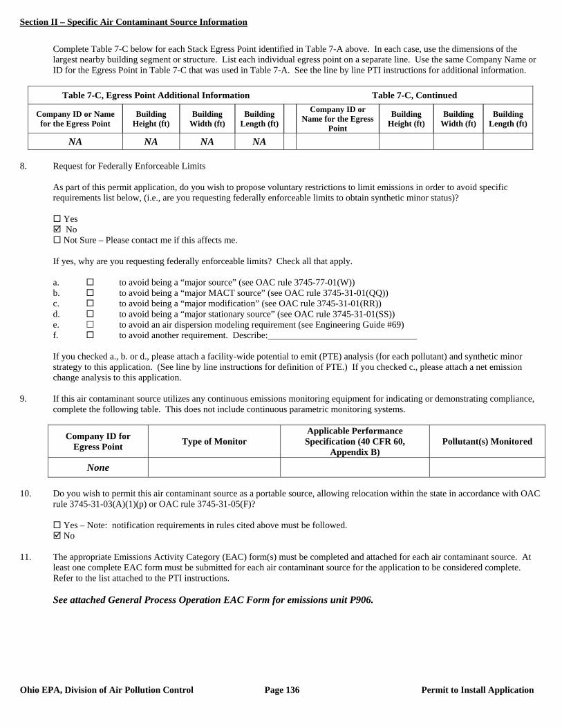
Section II – Specific Air Contaminant Source Information
Ohio EPA, Division of Air Pollution Control Page 136 Permit to Install Application
Complete Table 7-C below for each Stack Egress Point identified in Table 7-A above. In each case, use the dimensions of the largest nearby building segment or structure. List each individual egress point on a separate line. Use the same Company Name or ID for the Egress Point in Table 7-C that was used in Table 7-A. See the line by line PTI instructions for additional information.
Table 7-C, Egress Point Additional Information Table 7-C, Continued
Company ID or Name for the Egress Point
Building Height (ft)
Building Width (ft)
Building Length (ft)
Company ID or Name for the Egress
Point
Building Height (ft)
Building Width (ft)
Building Length (ft)
NA NA NA NA 8. Request for Federally Enforceable Limits
As part of this permit application, do you wish to propose voluntary restrictions to limit emissions in order to avoid specific requirements list below, (i.e., are you requesting federally enforceable limits to obtain synthetic minor status)?
Yes No Not Sure – Please contact me if this affects me.
If yes, why are you requesting federally enforceable limits? Check all that apply. a. to avoid being a “major source” (see OAC rule 3745-77-01(W)) b. to avoid being a “major MACT source” (see OAC rule 3745-31-01(QQ)) c. to avoid being a “major modification” (see OAC rule 3745-31-01(RR)) d. to avoid being a “major stationary source” (see OAC rule 3745-31-01(SS)) e. to avoid an air dispersion modeling requirement (see Engineering Guide #69) f. to avoid another requirement. Describe: If you checked a., b. or d., please attach a facility-wide potential to emit (PTE) analysis (for each pollutant) and synthetic minor strategy to this application. (See line by line instructions for definition of PTE.) If you checked c., please attach a net emission change analysis to this application.
9. If this air contaminant source utilizes any continuous emissions monitoring equipment for indicating or demonstrating compliance, complete the following table. This does not include continuous parametric monitoring systems.
Company ID for Egress Point Type of Monitor
Applicable Performance Specification (40 CFR 60,
Appendix B) Pollutant(s) Monitored
None
10. Do you wish to permit this air contaminant source as a portable source, allowing relocation within the state in accordance with OAC
rule 3745-31-03(A)(1)(p) or OAC rule 3745-31-05(F)?
Yes – Note: notification requirements in rules cited above must be followed. No
11. The appropriate Emissions Activity Category (EAC) form(s) must be completed and attached for each air contaminant source. At
least one complete EAC form must be submitted for each air contaminant source for the application to be considered complete. Refer to the list attached to the PTI instructions. See attached General Process Operation EAC Form for emissions unit P906.

Section II – Specific Air Contaminant Source Information
Ohio EPA, Division of Air Pollution Control Page 137 Permit to Install Application
EMISSIONS ACTIVITY CATEGORY FORM
GENERAL PROCESS OPERATION This form is to be completed for each process operation when there is no specific emissions activity category (EAC) form applicable. If there is more than one end product for this process, copy and complete this form for each additional product (see instructions). Several State/Federal regulations which may apply to process operations are listed in the instructions. Note that there may be other regulations which apply to this emissions unit which are not included in this list. 1. Reason this form is being submitted (Check one): New Permit Renewal or Modification of Air Permit Number(s) (e.g. P001) 2. Maximum Operating Schedule: 24 hours per day; 365 days per year
If the schedule is less than 24 hours/day or 365 days/year, what limits the schedule to less than maximum? See instructions for examples.
3. End product of this process: Flyash Waste 4. Hourly production rates (indicate appropriate units). Please see the instructions for clarification of “Maximum” and “Average” for
new versus existing operations:
Hourly Rate Units (e.g., widgets)
Average production 14.19 Tons of Flyash
Maximum production 14.19 Tons of Flyash 5. Annual production rates (indicate appropriate units) Please see the instructions for clarification of “Maximum” and “Actual” for new
versus existing operations:
Annual Rate Units (e.g., widgets)
Actual production 99,449 Tons of Flyash
Maximum production 124,311 Tons of Flyash 6. Type of operation (please check one):
Continuous Batch (please complete items below)
Minimum cycle* time (minutes): Minimum time between cycles (minutes): Maximum number of cycles per daily 24 hour period:
(Note: include cycle time and set up/clean up time.)
*”Cycle” refers to the time the equipment is in operation.

Section II – Specific Air Contaminant Source Information
Ohio EPA, Division of Air Pollution Control Page 138 Permit to Install Application
7. Materials used in process at maximum hourly production rate (add rows/pages as needed):
Material Physical State at Standard Conditions
Principle Use Amount**
Flyash Solid Waste Material 124,311 tons/yr ** Please indicate the amount and rate (e.g., lbs/hr, gallons/hr, lbs/cycle, etc.). 8. Please provide a narrative description of the process below (e.g., coating of metal parts using high VOC content coatings for the
manufacture of widgets; emissions controlled by thermal oxidizer...): The Flyash Conveying, Handling & Storage emissions unit (P906) includes all of the components associated with the
management of flyash produced by the baghouse control systems for main boiler B002.
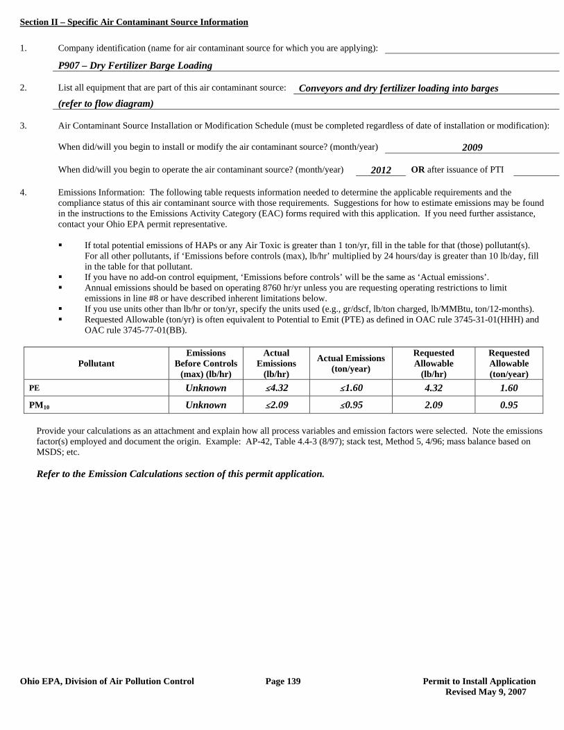
Section II – Specific Air Contaminant Source Information
Ohio EPA, Division of Air Pollution Control Page 139 Permit to Install Application Revised May 9, 2007
1. Company identification (name for air contaminant source for which you are applying):
P907 – Dry Fertilizer Barge Loading 2. List all equipment that are part of this air contaminant source: Conveyors and dry fertilizer loading into barges (refer to flow diagram) 3. Air Contaminant Source Installation or Modification Schedule (must be completed regardless of date of installation or modification): When did/will you begin to install or modify the air contaminant source? (month/year) 2009 When did/will you begin to operate the air contaminant source? (month/year) 2012 OR after issuance of PTI 4. Emissions Information: The following table requests information needed to determine the applicable requirements and the compliance status of this air contaminant source with those requirements. Suggestions for how to estimate emissions may be found in the instructions to the Emissions Activity Category (EAC) forms required with this application. If you need further assistance, contact your Ohio EPA permit representative.
If total potential emissions of HAPs or any Air Toxic is greater than 1 ton/yr, fill in the table for that (those) pollutant(s).
For all other pollutants, if ‘Emissions before controls (max), lb/hr’ multiplied by 24 hours/day is greater than 10 lb/day, fill in the table for that pollutant.
If you have no add-on control equipment, ‘Emissions before controls’ will be the same as ‘Actual emissions’. Annual emissions should be based on operating 8760 hr/yr unless you are requesting operating restrictions to limit
emissions in line #8 or have described inherent limitations below. If you use units other than lb/hr or ton/yr, specify the units used (e.g., gr/dscf, lb/ton charged, lb/MMBtu, ton/12-months). Requested Allowable (ton/yr) is often equivalent to Potential to Emit (PTE) as defined in OAC rule 3745-31-01(HHH) and
OAC rule 3745-77-01(BB).
Pollutant Emissions
Before Controls (max) (lb/hr)
Actual Emissions
(lb/hr)
Actual Emissions (ton/year)
Requested Allowable
(lb/hr)
Requested Allowable (ton/year)
PE Unknown #4.32 #1.60 4.32 1.60
PM10 Unknown #2.09 #0.95 2.09 0.95
Provide your calculations as an attachment and explain how all process variables and emission factors were selected. Note the emissions factor(s) employed and document the origin. Example: AP-42, Table 4.4-3 (8/97); stack test, Method 5, 4/96; mass balance based on MSDS; etc.
Refer to the Emission Calculations section of this permit application.
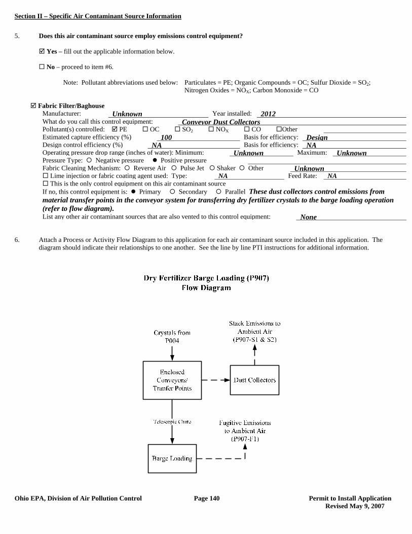
Section II – Specific Air Contaminant Source Information
Ohio EPA, Division of Air Pollution Control Page 140 Permit to Install Application Revised May 9, 2007
5. Does this air contaminant source employ emissions control equipment? Yes – fill out the applicable information below. No – proceed to item #6. Note: Pollutant abbreviations used below: Particulates = PE; Organic Compounds = OC; Sulfur Dioxide = SO2; Nitrogen Oxides = NOX; Carbon Monoxide = CO
Fabric Filter/Baghouse Manufacturer: Unknown Year installed: 2012 What do you call this control equipment: Conveyor Dust Collectors Pollutant(s) controlled: PE OC SO2 NOX CO Other Estimated capture efficiency (%) 100 Basis for efficiency: Design Design control efficiency (%) NA Basis for efficiency: NA Operating pressure drop range (inches of water): Minimum: Unknown Maximum: Unknown Pressure Type: Negative pressure Positive pressure Fabric Cleaning Mechanism: Reverse Air Pulse Jet Shaker Other Unknown Lime injection or fabric coating agent used: Type: NA Feed Rate: NA This is the only control equipment on this air contaminant source If no, this control equipment is: Primary Secondary Parallel These dust collectors control emissions from
material transfer points in the conveyor system for transferring dry fertilizer crystals to the barge loading operation (refer to flow diagram).
List any other air contaminant sources that are also vented to this control equipment: None 6. Attach a Process or Activity Flow Diagram to this application for each air contaminant source included in this application. The
diagram should indicate their relationships to one another. See the line by line PTI instructions for additional information.
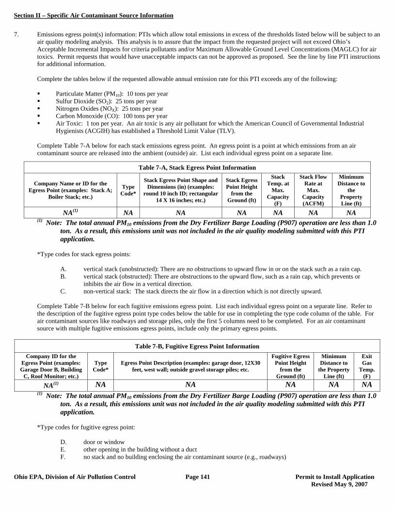
Section II – Specific Air Contaminant Source Information
Ohio EPA, Division of Air Pollution Control Page 141 Permit to Install Application Revised May 9, 2007
7. Emissions egress point(s) information: PTIs which allow total emissions in excess of the thresholds listed below will be subject to an
air quality modeling analysis. This analysis is to assure that the impact from the requested project will not exceed Ohio’s Acceptable Incremental Impacts for criteria pollutants and/or Maximum Allowable Ground Level Concentrations (MAGLC) for air toxics. Permit requests that would have unacceptable impacts can not be approved as proposed. See the line by line PTI instructions for additional information.
Complete the tables below if the requested allowable annual emission rate for this PTI exceeds any of the following:
Particulate Matter (PM10): 10 tons per year Sulfur Dioxide (SO2): 25 tons per year Nitrogen Oxides (NOX): 25 tons per year Carbon Monoxide (CO): 100 tons per year Air Toxic: 1 ton per year. An air toxic is any air pollutant for which the American Council of Governmental Industrial
Hygienists (ACGIH) has established a Threshold Limit Value (TLV).
Complete Table 7-A below for each stack emissions egress point. An egress point is a point at which emissions from an air contaminant source are released into the ambient (outside) air. List each individual egress point on a separate line.
(1) Note: The total annual PM10 emissions from the Dry Fertilizer Barge Loading (P907) operation are less than 1.0 ton. As a result, this emissions unit was not included in the air quality modeling submitted with this PTI application.
*Type codes for stack egress points:
A. vertical stack (unobstructed): There are no obstructions to upward flow in or on the stack such as a rain cap. B. vertical stack (obstructed): There are obstructions to the upward flow, such as a rain cap, which prevents or
inhibits the air flow in a vertical direction. C. non-vertical stack: The stack directs the air flow in a direction which is not directly upward.
Complete Table 7-B below for each fugitive emissions egress point. List each individual egress point on a separate line. Refer to the description of the fugitive egress point type codes below the table for use in completing the type code column of the table. For air contaminant sources like roadways and storage piles, only the first 5 columns need to be completed. For an air contaminant source with multiple fugitive emissions egress points, include only the primary egress points.
Table 7-B, Fugitive Egress Point Information
Company ID for the Egress Point (examples: Garage Door B, Building
C, Roof Monitor; etc.)
Type Code*
Egress Point Description (examples: garage door, 12X30 feet, west wall; outside gravel storage piles; etc.
Fugitive Egress Point Height
from the Ground (ft)
Minimum Distance to
the Property Line (ft)
Exit Gas
Temp. (F)
NA(1) NA NA NA NA NA (1) Note: The total annual PM10 emissions from the Dry Fertilizer Barge Loading (P907) operation are less than 1.0
ton. As a result, this emissions unit was not included in the air quality modeling submitted with this PTI application.
*Type codes for fugitive egress point:
D. door or window E. other opening in the building without a duct F. no stack and no building enclosing the air contaminant source (e.g., roadways)
Table 7-A, Stack Egress Point Information
Company Name or ID for the Egress Point (examples: Stack A;
Boiler Stack; etc.)
Type Code*
Stack Egress Point Shape and Dimensions (in) (examples:
round 10 inch ID; rectangular 14 X 16 inches; etc.)
Stack Egress Point Height
from the Ground (ft)
Stack Temp. at
Max. Capacity
(F)
Stack Flow Rate at Max.
Capacity (ACFM)
Minimum Distance to
the Property Line (ft)
NA(1) NA NA NA NA NA NA
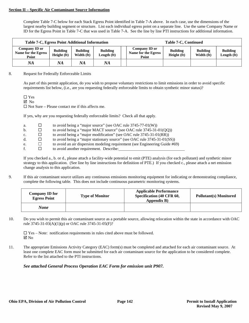
Section II – Specific Air Contaminant Source Information
Ohio EPA, Division of Air Pollution Control Page 142 Permit to Install Application Revised May 9, 2007
Complete Table 7-C below for each Stack Egress Point identified in Table 7-A above. In each case, use the dimensions of the largest nearby building segment or structure. List each individual egress point on a separate line. Use the same Company Name or ID for the Egress Point in Table 7-C that was used in Table 7-A. See the line by line PTI instructions for additional information.
Table 7-C, Egress Point Additional Information Table 7-C, Continued
Company ID or Name for the Egress
Point
Building Height (ft)
Building Width (ft)
Building Length (ft)
Company ID or Name for the Egress
Point
Building Height (ft)
Building Width (ft)
Building Length (ft)
NA NA NA NA 8. Request for Federally Enforceable Limits
As part of this permit application, do you wish to propose voluntary restrictions to limit emissions in order to avoid specific requirements list below, (i.e., are you requesting federally enforceable limits to obtain synthetic minor status)?
Yes No Not Sure – Please contact me if this affects me.
If yes, why are you requesting federally enforceable limits? Check all that apply. a. to avoid being a “major source” (see OAC rule 3745-77-01(W)) b. to avoid being a “major MACT source” (see OAC rule 3745-31-01(QQ)) c. to avoid being a “major modification” (see OAC rule 3745-31-01(RR)) d. to avoid being a “major stationary source” (see OAC rule 3745-31-01(SS)) e. to avoid an air dispersion modeling requirement (see Engineering Guide #69) f. to avoid another requirement. Describe: If you checked a., b. or d., please attach a facility-wide potential to emit (PTE) analysis (for each pollutant) and synthetic minor strategy to this application. (See line by line instructions for definition of PTE.) If you checked c., please attach a net emission change analysis to this application.
9. If this air contaminant source utilizes any continuous emissions monitoring equipment for indicating or demonstrating compliance, complete the following table. This does not include continuous parametric monitoring systems.
Company ID for Egress Point Type of Monitor
Applicable Performance Specification (40 CFR 60,
Appendix B) Pollutant(s) Monitored
None
10. Do you wish to permit this air contaminant source as a portable source, allowing relocation within the state in accordance with OAC
rule 3745-31-03(A)(1)(p) or OAC rule 3745-31-05(F)?
Yes – Note: notification requirements in rules cited above must be followed. No
11. The appropriate Emissions Activity Category (EAC) form(s) must be completed and attached for each air contaminant source. At
least one complete EAC form must be submitted for each air contaminant source for the application to be considered complete. Refer to the list attached to the PTI instructions. See attached General Process Operation EAC Form for emission unit P907.

Section II – Specific Air Contaminant Source Information
Ohio EPA, Division of Air Pollution Control Page 143 Permit to Install Application Revised May 9, 2007
EMISSIONS ACTIVITY CATEGORY FORM GENERAL PROCESS OPERATION
This form is to be completed for each process operation when there is no specific emissions activity category (EAC) form applicable. If there is more than one end product for this process, copy and complete this form for each additional product (see instructions). Several State/Federal regulations which may apply to process operations are listed in the instructions. Note that there may be other regulations which apply to this emissions unit which are not included in this list. 1. Reason this form is being submitted (Check one) New Permit Renewal or Modification of Air Permit Number(s) (e.g. P001) 2. Maximum Operating Schedule: : 24 hours per day; 365 days per year
If the schedule is less than 24 hours/day or 365 days/year, what limits the schedule to less than maximum? See instructions for examples.
3. End product of this process: Fertilizer 4. Hourly production rates (indicate appropriate units). Please see the instructions for clarification of “Maximum” and “Average” for
new versus existing operations:
Hourly Rate Units (e.g., widgets)
Average production 27 tons fertilizer
Maximum production 33 tons fertilizer 5. Annual production rates (indicate appropriate units) Please see the instructions for clarification of “Maximum” and “Actual” for new
versus existing operations:
Annual Rate Units (e.g., widgets)
Actual production 236,520 tons fertilizer
Maximum production 289,080 tons fertilizer 6. Type of operation (please check one):
Continuous Batch (please complete items below)
Minimum cycle* time (minutes): Minimum time between cycles (minutes): Maximum number of cycles per daily 24 hour period:
(Note: include cycle time and set up/clean up time.) *”Cycle” refers to the time the equipment is in operation.
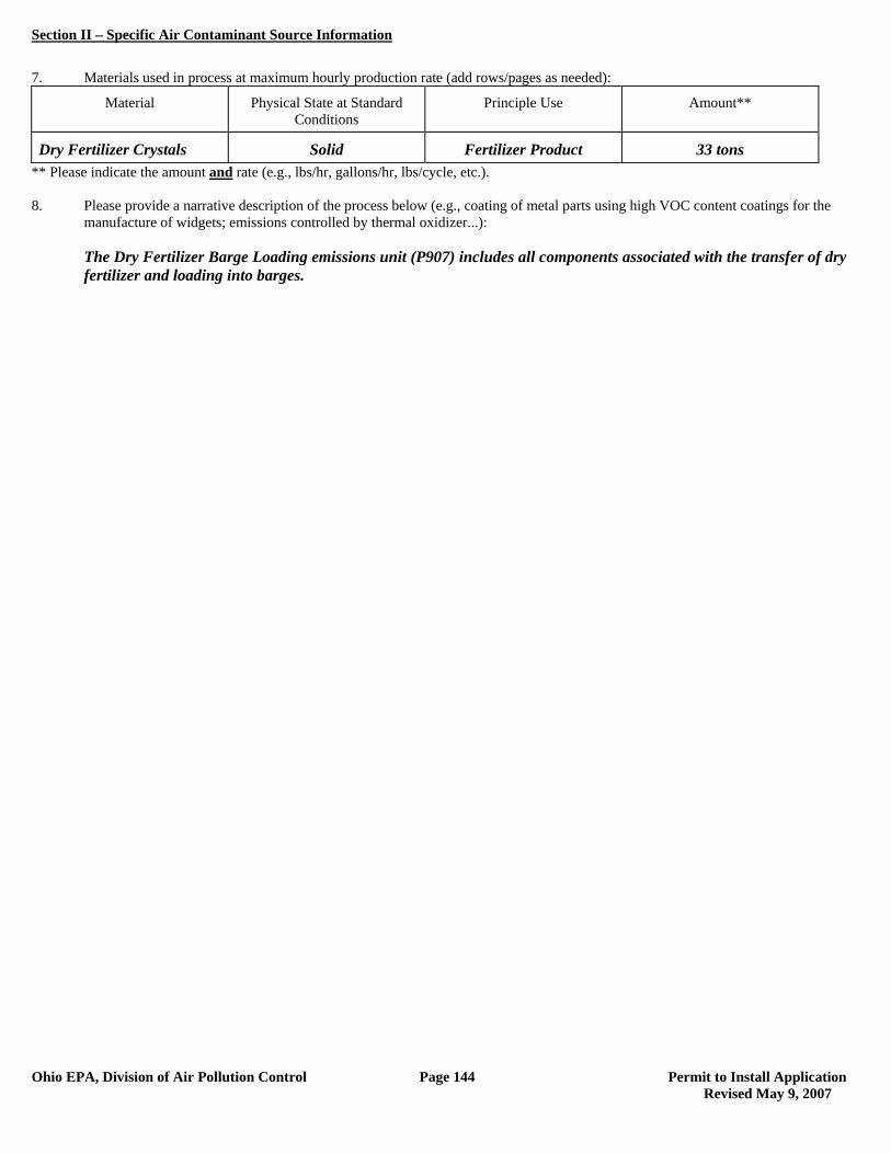
Section II – Specific Air Contaminant Source Information
Ohio EPA, Division of Air Pollution Control Page 144 Permit to Install Application Revised May 9, 2007
7. Materials used in process at maximum hourly production rate (add rows/pages as needed):
Material Physical State at Standard Conditions
Principle Use Amount**
Dry Fertilizer Crystals Solid Fertilizer Product 33 tons ** Please indicate the amount and rate (e.g., lbs/hr, gallons/hr, lbs/cycle, etc.). 8. Please provide a narrative description of the process below (e.g., coating of metal parts using high VOC content coatings for the
manufacture of widgets; emissions controlled by thermal oxidizer...): The Dry Fertilizer Barge Loading emissions unit (P907) includes all components associated with the transfer of dry
fertilizer and loading into barges.
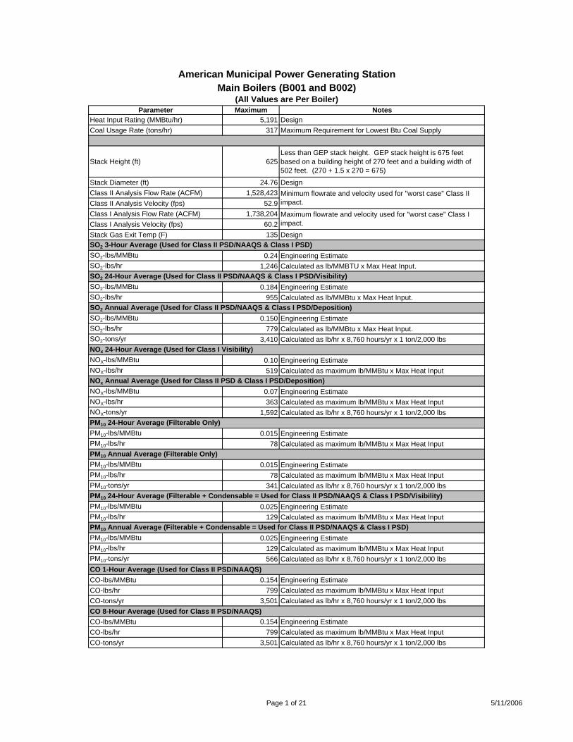
Main Boilers (B001 and B002)(All Values are Per Boiler)
Parameter Maximum NotesHeat Input Rating (MMBtu/hr) 5,191 DesignCoal Usage Rate (tons/hr) 317 Maximum Requirement for Lowest Btu Coal Supply
Stack Height (ft) 625Less than GEP stack height. GEP stack height is 675 feet based on a building height of 270 feet and a building width of 502 feet. (270 + 1.5 x 270 = 675)
Stack Diameter (ft) 24.76 DesignClass II Analysis Flow Rate (ACFM) 1,528,423Class II Analysis Velocity (fps) 52.9Class I Analysis Flow Rate (ACFM) 1,738,204Class I Analysis Velocity (fps) 60.2Stack Gas Exit Temp (F) 135 DesignSO2 3-Hour Average (Used for Class II PSD/NAAQS & Class I PSD)SO2-lbs/MMBtu 0.24 Engineering EstimateSO2-lbs/hr 1,246 Calculated as lb/MMBTU x Max Heat Input. SO2 24-Hour Average (Used for Class II PSD/NAAQS & Class I PSD/Visibility)SO2-lbs/MMBtu 0.184 Engineering EstimateSO2-lbs/hr 955 Calculated as lb/MMBtu x Max Heat Input. SO2 Annual Average (Used for Class II PSD/NAAQS & Class I PSD/Deposition)SO2-lbs/MMBtu 0.150 Engineering EstimateSO2-lbs/hr 779 Calculated as lb/MMBtu x Max Heat Input. SO2-tons/yr 3,410 Calculated as lb/hr x 8,760 hours/yr x 1 ton/2,000 lbsNOx 24-Hour Average (Used for Class I Visibility)NOX-lbs/MMBtu 0.10 Engineering EstimateNOX-lbs/hr 519 Calculated as maximum lb/MMBtu x Max Heat InputNOx Annual Average (Used for Class II PSD & Class I PSD/Deposition)NOX-lbs/MMBtu 0.07 Engineering EstimateNOX-lbs/hr 363 Calculated as maximum lb/MMBtu x Max Heat InputNOX-tons/yr 1,592 Calculated as lb/hr x 8,760 hours/yr x 1 ton/2,000 lbsPM10 24-Hour Average (Filterable Only)PM10-lbs/MMBtu 0.015 Engineering EstimatePM10-lbs/hr 78 Calculated as maximum lb/MMBtu x Max Heat InputPM10 Annual Average (Filterable Only)PM10-lbs/MMBtu 0.015 Engineering EstimatePM10-lbs/hr 78 Calculated as maximum lb/MMBtu x Max Heat InputPM10-tons/yr 341 Calculated as lb/hr x 8,760 hours/yr x 1 ton/2,000 lbsPM10 24-Hour Average (Filterable + Condensable = Used for Class II PSD/NAAQS & Class I PSD/Visibility)PM10-lbs/MMBtu 0.025 Engineering EstimatePM10-lbs/hr 129 Calculated as maximum lb/MMBtu x Max Heat InputPM10 Annual Average (Filterable + Condensable = Used for Class II PSD/NAAQS & Class I PSD)PM10-lbs/MMBtu 0.025 Engineering EstimatePM10-lbs/hr 129 Calculated as maximum lb/MMBtu x Max Heat InputPM10-tons/yr 566 Calculated as lb/hr x 8,760 hours/yr x 1 ton/2,000 lbsCO 1-Hour Average (Used for Class II PSD/NAAQS)CO-lbs/MMBtu 0.154 Engineering EstimateCO-lbs/hr 799 Calculated as maximum lb/MMBtu x Max Heat InputCO-tons/yr 3,501 Calculated as lb/hr x 8,760 hours/yr x 1 ton/2,000 lbsCO 8-Hour Average (Used for Class II PSD/NAAQS)CO-lbs/MMBtu 0.154 Engineering EstimateCO-lbs/hr 799 Calculated as maximum lb/MMBtu x Max Heat InputCO-tons/yr 3,501 Calculated as lb/hr x 8,760 hours/yr x 1 ton/2,000 lbs
Minimum flowrate and velocity used for "worst case" Class II impact.
Maximum flowrate and velocity used for "worst case" Class I impact.
American Municipal Power Generating Station
Page 1 of 21 5/11/2006
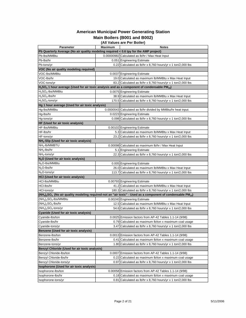
Main Boilers (B001 and B002)(All Values are Per Boiler)
Parameter Maximum Notes
American Municipal Power Generating Station
Pb Quarterly Average (No air quality modeling required < 0.6 tpy for the AMP project)Pb-lbs/MMBtu 0.00000982 Calculated as lb/hr / Max Heat InputPb-lbs/hr 0.051 Engineering EstimatePb-tons/yr 0.22 Calculated as lb/hr x 8,760 hours/yr x 1 ton/2,000 lbsVOC (No air quality modeling required)VOC-lbs/MMBtu 0.0037 Engineering EstimateVOC-lbs/hr 19.0 Calculated as maximum lb/MMBtu x Max Heat InputVOC-tons/yr 83.2 Calculated as lb/hr x 8,760 hours/yr x 1 ton/2,000 lbsH2SO4 1 hour average (Used for air toxic analysis and as a component of condensable PM10)H2SO4-lbs/MMBtu 0.0075 Engineering EstimateH2SO4-lbs/hr 38.9 Calculated as maximum lb/MMBtu x Max Heat InputH2SO4-tons/yr 170.5 Calculated as lb/hr x 8,760 hours/yr x 1 ton/2,000 lbsHg 1 hour average (Used for air toxic analysis)Hg-lbs/MMBtu 0.0000043 Calculated as lb/hr divided by MMBtu/hr heat input.Hg-lbs/hr 0.0223 Engineering EstimateHg-tons/yr 0.098 Calculated as lb/hr x 8,760 hours/yr x 1 ton/2,000 lbsHF (Used for air toxic analysis)HF-lbs/MMBtu 0.00102 Engineering EstimateHF-lbs/hr 5.3 Calculated as maximum lb/MMBtu x Max Heat InputHF-tons/yr 23.2 Calculated as lb/hr x 8,760 hours/yr x 1 ton/2,000 lbsNH3-Slip (Used for air toxic analysis)NH3-lb/MMBTU 0.00098 Calculated as maximum lb/hr / Max Heat Input NH3-lbs/hr 5.1 Engineering EstimateNH3-tons/yr 22.3 Calculated as lb/hr x 8,760 hours/yr x 1 ton/2,000 lbsN2O (Used for air toxic analysis)N2O-lbs/MMBtu 0.005 Engineering EstimateN2O-lbs/hr 26.0 Calculated as maximum lb/MMBtu x Max Heat InputN2O-tons/yr 113.7 Calculated as lb/hr x 8,760 hours/yr x 1 ton/2,000 lbsHCl (Used for air toxic analysis)HCl-lbs/MMBtu 0.00793 Engineering EstimateHCl-lbs/hr 41.2 Calculated as maximum lb/MMBtu x Max Heat InputHCl-tons/yr 180.3 Calculated as lb/hr x 8,760 hours/yr x 1 ton/2,000 lbs(NH4)2SO4 (No air quality modeling required-not an "air toxic" - Used as a component of condensable PM10)(NH4)2SO4-lbs/MMBtu 0.00240 Engineering Estimate(NH4)2SO4-lbs/hr 12.5 Calculated as maximum lb/MMBtu x Max Heat Input(NH4)2SO4-tons/yr 54.6 Calculated as lb/hr x 8,760 hours/yr x 1 ton/2,000 lbsCyanide (Used for air toxic analysis)Cyanide-lbs/ton 0.0025 Emission factors from AP-42 Tables 1.1-14 (9/98)Cyanide-lbs/hr 0.79 Calculated as maximum lb/ton x maximum coal usageCyanide-tons/yr 3.47 Calculated as lb/hr x 8,760 hours/yr x 1 ton/2,000 lbsBenzene (Used for air toxic analysis)Benzene-lbs/ton 0.0013 Emission factors from AP-42 Tables 1.1-14 (9/98)Benzene-lbs/hr 0.41 Calculated as maximum lb/ton x maximum coal usageBenzene-tons/yr 1.80 Calculated as lb/hr x 8,760 hours/yr x 1 ton/2,000 lbsBenzyl Chloride (Used for air toxic analysis)Benzyl Chloride-lbs/ton 0.0007 Emission factors from AP-42 Tables 1.1-14 (9/98)Benzyl Chloride-lbs/hr 0.22 Calculated as maximum lb/ton x maximum coal usageBenzyl Chloride-tons/yr 0.97 Calculated as lb/hr x 8,760 hours/yr x 1 ton/2,000 lbsIsophorone (Used for air toxic analysis)Isophorone-lbs/ton 0.00058 Emission factors from AP-42 Tables 1.1-14 (9/98)Isophorone-lbs/hr 0.18 Calculated as maximum lb/ton x maximum coal usageIsophorone-tons/yr 0.81 Calculated as lb/hr x 8,760 hours/yr x 1 ton/2,000 lbs
Page 2 of 21 5/11/2006
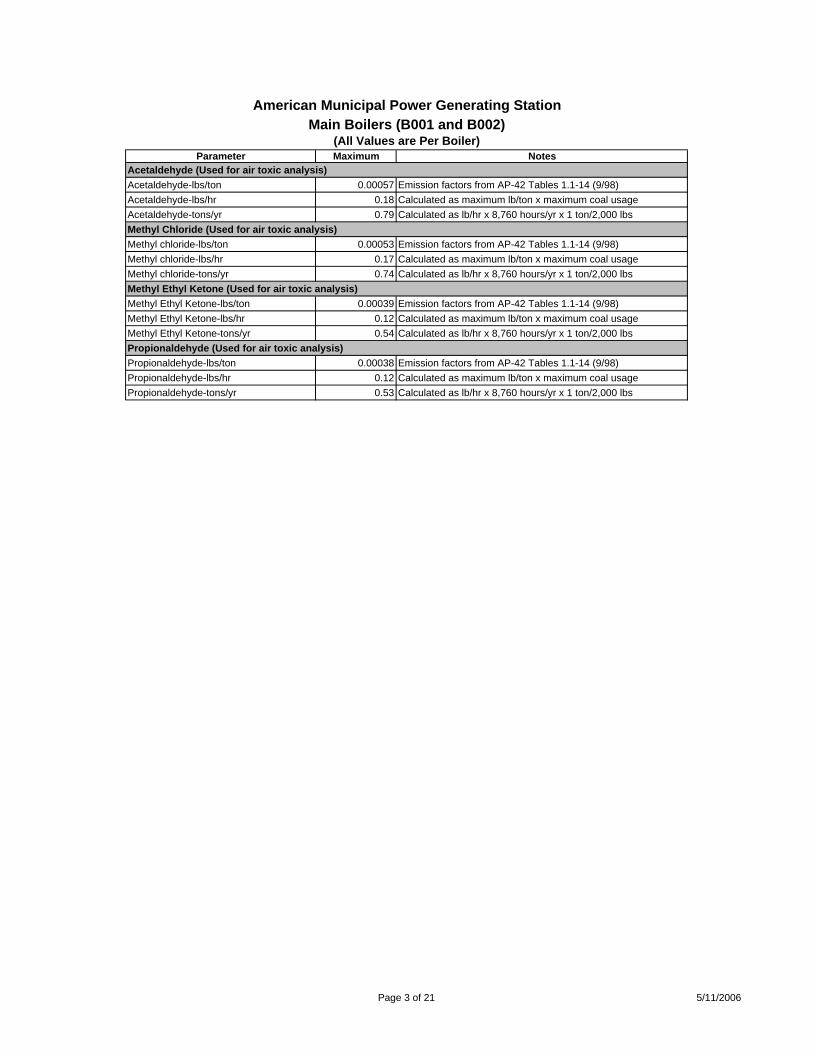
Main Boilers (B001 and B002)(All Values are Per Boiler)
Parameter Maximum Notes
American Municipal Power Generating Station
Acetaldehyde (Used for air toxic analysis)Acetaldehyde-lbs/ton 0.00057 Emission factors from AP-42 Tables 1.1-14 (9/98)Acetaldehyde-lbs/hr 0.18 Calculated as maximum lb/ton x maximum coal usageAcetaldehyde-tons/yr 0.79 Calculated as lb/hr x 8,760 hours/yr x 1 ton/2,000 lbsMethyl Chloride (Used for air toxic analysis)Methyl chloride-lbs/ton 0.00053 Emission factors from AP-42 Tables 1.1-14 (9/98)Methyl chloride-lbs/hr 0.17 Calculated as maximum lb/ton x maximum coal usageMethyl chloride-tons/yr 0.74 Calculated as lb/hr x 8,760 hours/yr x 1 ton/2,000 lbsMethyl Ethyl Ketone (Used for air toxic analysis)Methyl Ethyl Ketone-lbs/ton 0.00039 Emission factors from AP-42 Tables 1.1-14 (9/98)Methyl Ethyl Ketone-lbs/hr 0.12 Calculated as maximum lb/ton x maximum coal usageMethyl Ethyl Ketone-tons/yr 0.54 Calculated as lb/hr x 8,760 hours/yr x 1 ton/2,000 lbsPropionaldehyde (Used for air toxic analysis)Propionaldehyde-lbs/ton 0.00038 Emission factors from AP-42 Tables 1.1-14 (9/98)Propionaldehyde-lbs/hr 0.12 Calculated as maximum lb/ton x maximum coal usagePropionaldehyde-tons/yr 0.53 Calculated as lb/hr x 8,760 hours/yr x 1 ton/2,000 lbs
Page 3 of 21 5/11/2006
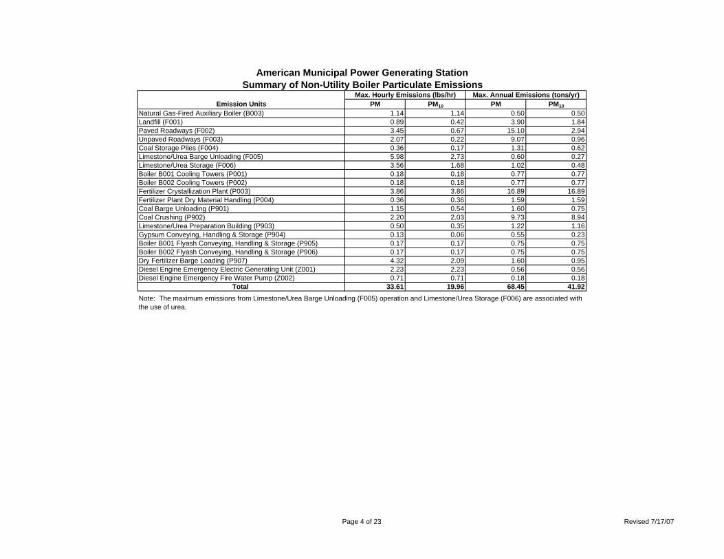
American Municipal Power Generating StationSummary of Non-Utility Boiler Particulate Emissions
Max. Hourly Emissions (lbs/hr) Max. Annual Emissions (tons/yr)Emission Units PM PM10 PM PM10
Natural Gas-Fired Auxiliary Boiler (B003) 1.14 1.14 0.50 0.50Landfill (F001) 0.89 0.42 3.90 1.84Paved Roadways (F002) 3.45 0.67 15.10 2.94Unpaved Roadways (F003) 2.07 0.22 9.07 0.96Coal Storage Piles (F004) 0.36 0.17 1.31 0.62Limestone/Urea Barge Unloading (F005) 5.98 2.73 0.60 0.27Limestone/Urea Storage (F006) 3.56 1.68 1.02 0.48Boiler B001 Cooling Towers (P001) 0.18 0.18 0.77 0.77Boiler B002 Cooling Towers (P002) 0.18 0.18 0.77 0.77Fertilizer Crystallization Plant (P003) 3.86 3.86 16.89 16.89Fertilizer Plant Dry Material Handling (P004) 0.36 0.36 1.59 1.59Coal Barge Unloading (P901) 1.15 0.54 1.60 0.75Coal Crushing (P902) 2.20 2.03 9.73 8.94Limestone/Urea Preparation Building (P903) 0.50 0.35 1.22 1.16Gypsum Conveying, Handling & Storage (P904) 0.13 0.06 0.55 0.23Boiler B001 Flyash Conveying, Handling & Storage (P905) 0.17 0.17 0.75 0.75Boiler B002 Flyash Conveying, Handling & Storage (P906) 0.17 0.17 0.75 0.75Dry Fertilizer Barge Loading (P907) 4.32 2.09 1.60 0.95Diesel Engine Emergency Electric Generating Unit (Z001) 2.23 2.23 0.56 0.56Diesel Engine Emergency Fire Water Pump (Z002) 0.71 0.71 0.18 0.18
Total 33.61 19.96 68.45 41.92Note: The maximum emissions from Limestone/Urea Barge Unloading (F005) operation and Limestone/Urea Storage (F006) are associated with the use of urea.
Page 4 of 23 Revised 7/17/07
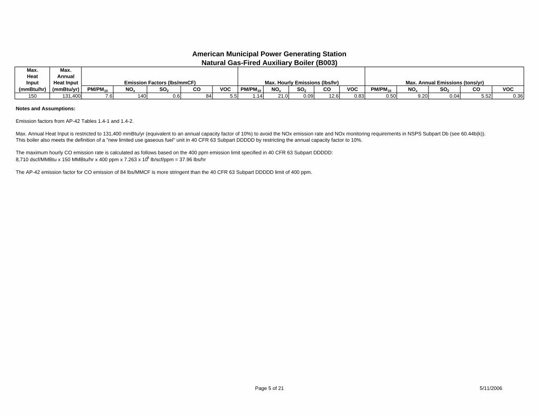
American Municipal Power Generating StationNatural Gas-Fired Auxiliary Boiler (B003)
Max. Max.Heat AnnualInput Heat Input Emission Factors (lbs/mmCF) Max. Hourly Emissions (lbs/hr) Max. Annual Emissions (tons/yr)
(mmBtu/hr) (mmBtu/yr) PM/PM10 NOx SO2 CO VOC PM/PM10 NOx SO2 CO VOC PM/PM10 NOx SO2 CO VOC150 131,400 7.6 140 0.6 84 5.5 1.14 21.0 0.09 12.6 0.83 0.50 9.20 0.04 5.52 0.36
Notes and Assumptions:
Emission factors from AP-42 Tables 1.4-1 and 1.4-2.
Max. Annual Heat Input is restricted to 131,400 mmBtu/yr (equivalent to an annual capacity factor of 10%) to avoid the NOx emission rate and NOx monitoring requirements in NSPS Subpart Db (see 60.44b(k)).This boiler also meets the definition of a "new limited use gaseous fuel" unit in 40 CFR 63 Subpart DDDDD by restricting the annual capacity factor to 10%.
The maximum hourly CO emission rate is calculated as follows based on the 400 ppm emission limit specified in 40 CFR 63 Subpart DDDDD:8,710 dscf/MMBtu x 150 MMBtu/hr x 400 ppm x 7.263 x 10-8 lb/scf/ppm = 37.96 lbs/hr
The AP-42 emission factor for CO emission of 84 lbs/MMCF is more stringent than the 40 CFR 63 Subpart DDDDD limit of 400 ppm.
Page 5 of 21 5/11/2006
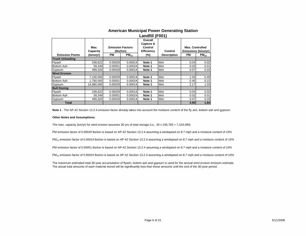
American Municipal Power Generating StationLandfill (F001)
OverallCapture &
Max. Emission Factors Control Max. Controlled Capacity (lbs/ton) Efficiency Control Emissions (tons/yr)
Emission Points (tons/yr) PM PM10 (%) Description PM PM10Truck UnloadingFlyash 248,622 0.00029 0.00014 Note 1 Wet 0.04 0.02Bottom Ash 59,349 0.00051 0.00024 Note 1 Wet 0.02 0.01Gypsum 499,320 0.00029 0.00014 Note 1 Wet 0.07 0.03Wind ErosionFlyash 7,100,000 0.00029 0.00014 Note 1 Wet 1.03 0.49Bottom Ash 1,780,000 0.00051 0.00024 Note 1 Wet 0.45 0.22Gypsum 14,980,000 0.00029 0.00014 Note 1 Wet 2.17 1.03Bull DozingFlyash 248,622 0.00029 0.00014 Note 1 Wet 0.04 0.02Bottom Ash 59,349 0.00051 0.00024 Note 1 Wet 0.02 0.01Gypsum 499,320 0.00029 0.00014 Note 1 Wet 0.07 0.03
Total 3.90 1.84
Note 1 - The AP-42 Section 13.2.4 emission factor already takes into account the moisture content of the fly ash, bottom ash and gypsum.
Other Notes and Assumptions:
The max. capacity (ton/yr) for wind erosion assumes 30 yrs of total storage (i.e., 30 x 236,783 = 7,103,490)
PM emission factor of 0.00029 lbs/ton is based on AP-42 Section 13.2.4 assuming a windspeed on 8.7 mph and a moisture content of 15%
PM10 emission factor of 0.00014 lbs/ton is based on AP-42 Section 13.2.4 assuming a windspeed on 8.7 mph and a moisture content of 15%
PM emission factor of 0.00051 lbs/ton is based on AP-42 Section 13.2.4 assuming a windspeed on 8.7 mph and a moisture content of 10%
PM10 emission factor of 0.00024 lbs/ton is based on AP-42 Section 13.2.4 assuming a windspeed on 8.7 mph and a moisture content of 10%
The maximum estimated total 30-year accumulation of flyash, bottom ash and gypsum is used for the annual wind erosion emisson estimate.The actual total amounts of each material stored will be significantly less than these amounts until the end of the 30-year period.
Page 6 of 21 5/11/2006
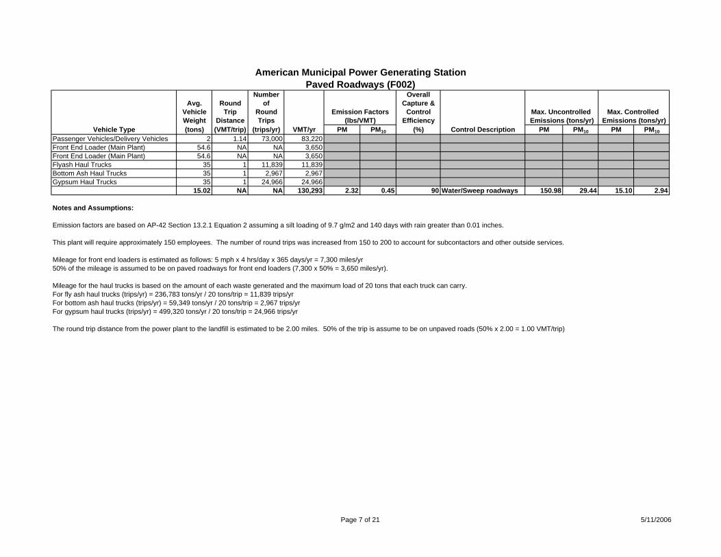
American Municipal Power Generating StationPaved Roadways (F002)
Number OverallAvg. Round of Capture &
Vehicle Trip Round Emission Factors Control Max. Uncontrolled Max. Controlled Weight Distance Trips (lbs/VMT) Efficiency Emissions (tons/yr) Emissions (tons/yr)
Vehicle Type (tons) (VMT/trip) (trips/yr) VMT/yr PM PM10 (%) Control Description PM PM10 PM PM10Passenger Vehicles/Delivery Vehicles 2 1.14 73,000 83,220Front End Loader (Main Plant) 54.6 NA NA 3,650Front End Loader (Main Plant) 54.6 NA NA 3,650Flyash Haul Trucks 35 1 11,839 11,839Bottom Ash Haul Trucks 35 1 2,967 2,967Gypsum Haul Trucks 35 1 24,966 24,966
15.02 NA NA 130,293 2.32 0.45 90 Water/Sweep roadways 150.98 29.44 15.10 2.94
Notes and Assumptions:
Emission factors are based on AP-42 Section 13.2.1 Equation 2 assuming a silt loading of 9.7 g/m2 and 140 days with rain greater than 0.01 inches.
This plant will require approximately 150 employees. The number of round trips was increased from 150 to 200 to account for subcontactors and other outside services.
Mileage for front end loaders is estimated as follows: 5 mph x 4 hrs/day x 365 days/yr = 7,300 miles/yr 50% of the mileage is assumed to be on paved roadways for front end loaders (7,300 x 50% = 3,650 miles/yr).
Mileage for the haul trucks is based on the amount of each waste generated and the maximum load of 20 tons that each truck can carry.For fly ash haul trucks (trips/yr) = 236,783 tons/yr / 20 tons/trip = 11,839 trips/yrFor bottom ash haul trucks (trips/yr) = 59,349 tons/yr / 20 tons/trip = 2,967 trips/yrFor gypsum haul trucks (trips/yr) = 499,320 tons/yr / 20 tons/trip = 24,966 trips/yr
The round trip distance from the power plant to the landfill is estimated to be 2.00 miles. 50% of the trip is assume to be on unpaved roads (50% x 2.00 = 1.00 VMT/trip)
Page 7 of 21 5/11/2006
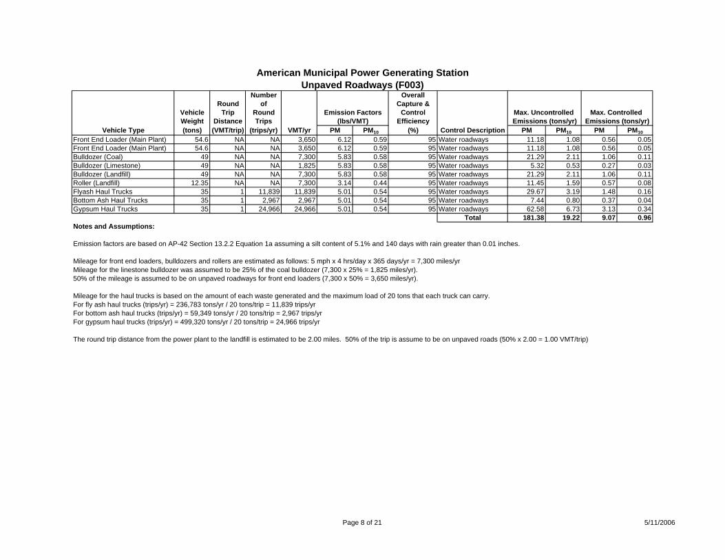
American Municipal Power Generating StationUnpaved Roadways (F003)
Number OverallRound of Capture &
Vehicle Trip Round Emission Factors Control Max. Uncontrolled Max. Controlled Weight Distance Trips (lbs/VMT) Efficiency Emissions (tons/yr) Emissions (tons/yr)
Vehicle Type (tons) (VMT/trip) (trips/yr) VMT/yr PM PM10 (%) Control Description PM PM10 PM PM10Front End Loader (Main Plant) 54.6 NA NA 3,650 6.12 0.59 95 Water roadways 11.18 1.08 0.56 0.05Front End Loader (Main Plant) 54.6 NA NA 3,650 6.12 0.59 95 Water roadways 11.18 1.08 0.56 0.05Bulldozer (Coal) 49 NA NA 7,300 5.83 0.58 95 Water roadways 21.29 2.11 1.06 0.11Bulldozer (Limestone) 49 NA NA 1,825 5.83 0.58 95 Water roadways 5.32 0.53 0.27 0.03Bulldozer (Landfill) 49 NA NA 7,300 5.83 0.58 95 Water roadways 21.29 2.11 1.06 0.11Roller (Landfill) 12.35 NA NA 7,300 3.14 0.44 95 Water roadways 11.45 1.59 0.57 0.08Flyash Haul Trucks 35 1 11,839 11,839 5.01 0.54 95 Water roadways 29.67 3.19 1.48 0.16Bottom Ash Haul Trucks 35 1 2,967 2,967 5.01 0.54 95 Water roadways 7.44 0.80 0.37 0.04Gypsum Haul Trucks 35 1 24,966 24,966 5.01 0.54 95 Water roadways 62.58 6.73 3.13 0.34
Total 181.38 19.22 9.07 0.96Notes and Assumptions:
Emission factors are based on AP-42 Section 13.2.2 Equation 1a assuming a silt content of 5.1% and 140 days with rain greater than 0.01 inches.
Mileage for front end loaders, bulldozers and rollers are estimated as follows: 5 mph x 4 hrs/day x 365 days/yr = 7,300 miles/yr Mileage for the linestone bulldozer was assumed to be 25% of the coal bulldozer (7,300 x 25% = 1,825 miles/yr).50% of the mileage is assumed to be on unpaved roadways for front end loaders (7,300 x 50% = 3,650 miles/yr).
Mileage for the haul trucks is based on the amount of each waste generated and the maximum load of 20 tons that each truck can carry.For fly ash haul trucks (trips/yr) = 236,783 tons/yr / 20 tons/trip = 11,839 trips/yrFor bottom ash haul trucks (trips/yr) = 59,349 tons/yr / 20 tons/trip = 2,967 trips/yrFor gypsum haul trucks (trips/yr) = 499,320 tons/yr / 20 tons/trip = 24,966 trips/yr
The round trip distance from the power plant to the landfill is estimated to be 2.00 miles. 50% of the trip is assume to be on unpaved roads (50% x 2.00 = 1.00 VMT/trip)
Page 8 of 21 5/11/2006
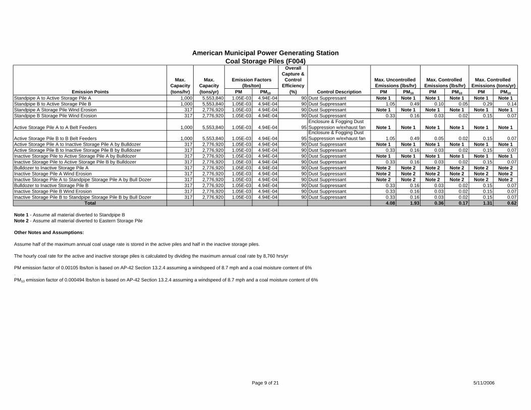
American Municipal Power Generating StationCoal Storage Piles (F004)
OverallCapture &
Max. Max. Emission Factors Control Max. Uncontrolled Max. Controlled Max. Controlled Capacity Capacity (lbs/ton) Efficiency Emissions (lbs/hr) Emissions (lbs/hr) Emissions (tons/yr)
Emission Points (tons/hr) (tons/yr) PM PM10 (%) Control Description PM PM10 PM PM10 PM PM10Standpipe A to Active Storage Pile A 1,000 5,553,840 1.05E-03 4.94E-04 90 Dust Suppressant Note 1 Note 1 Note 1 Note 1 Note 1 Note 1Standpipe B to Active Storage Pile B 1,000 5,553,840 1.05E-03 4.94E-04 90 Dust Suppressant 1.05 0.49 0.10 0.05 0.29 0.14Standpipe A Storage Pile Wind Erosion 317 2,776,920 1.05E-03 4.94E-04 90 Dust Suppressant Note 1 Note 1 Note 1 Note 1 Note 1 Note 1Standpipe B Storage Pile Wind Erosion 317 2,776,920 1.05E-03 4.94E-04 90 Dust Suppressant 0.33 0.16 0.03 0.02 0.15 0.07
Active Storage Pile A to A Belt Feeders 1,000 5,553,840 1.05E-03 4.94E-04 95Enclosure & Fogging Dust Suppression w/exhaust fan Note 1 Note 1 Note 1 Note 1 Note 1 Note 1
Active Storage Pile B to B Belt Feeders 1,000 5,553,840 1.05E-03 4.94E-04 95Enclosure & Fogging Dust Suppression w/exhaust fan 1.05 0.49 0.05 0.02 0.15 0.07
Active Storage Pile A to Inactive Storage Pile A by Bulldozer 317 2,776,920 1.05E-03 4.94E-04 90 Dust Suppressant Note 1 Note 1 Note 1 Note 1 Note 1 Note 1Active Storage Pile B to Inactive Storage Pile B by Bulldozer 317 2,776,920 1.05E-03 4.94E-04 90 Dust Suppressant 0.33 0.16 0.03 0.02 0.15 0.07Inactive Storage Pile to Active Storage Pile A by Bulldozer 317 2,776,920 1.05E-03 4.94E-04 90 Dust Suppressant Note 1 Note 1 Note 1 Note 1 Note 1 Note 1Inactive Storage Pile to Active Storage Pile B by Bulldozer 317 2,776,920 1.05E-03 4.94E-04 90 Dust Suppressant 0.33 0.16 0.03 0.02 0.15 0.07Bulldozer to Inactive Storage Pile A 317 2,776,920 1.05E-03 4.94E-04 90 Dust Suppressant Note 2 Note 2 Note 2 Note 2 Note 2 Note 2Inactive Storage Pile A Wind Erosion 317 2,776,920 1.05E-03 4.94E-04 90 Dust Suppressant Note 2 Note 2 Note 2 Note 2 Note 2 Note 2Inactive Storage Pile A to Standpipe Storage Pile A by Bull Dozer 317 2,776,920 1.05E-03 4.94E-04 90 Dust Suppressant Note 2 Note 2 Note 2 Note 2 Note 2 Note 2Bulldozer to Inactive Storage Pile B 317 2,776,920 1.05E-03 4.94E-04 90 Dust Suppressant 0.33 0.16 0.03 0.02 0.15 0.07Inactive Storage Pile B Wind Erosion 317 2,776,920 1.05E-03 4.94E-04 90 Dust Suppressant 0.33 0.16 0.03 0.02 0.15 0.07Inactive Storage Pile B to Standpipe Storage Pile B by Bull Dozer 317 2,776,920 1.05E-03 4.94E-04 90 Dust Suppressant 0.33 0.16 0.03 0.02 0.15 0.07
Total 4.08 1.93 0.36 0.17 1.31 0.62
Note 1 - Assume all material diverted to Standpipe BNote 2 - Assume all material diverted to Eastern Storage Pile
Other Notes and Assumptions:
Assume half of the maximum annual coal usage rate is stored in the active piles and half in the inactive storage piles.
The hourly coal rate for the active and inactive storage piles is calculated by dividing the maximum annual coal rate by 8,760 hrs/yr
PM emission factor of 0.00105 lbs/ton is based on AP-42 Section 13.2.4 assuming a windspeed of 8.7 mph and a coal moisture content of 6%.PM10 emission factor of 0.000494 lbs/ton is based on AP-42 Section 13.2.4 assuming a windspeed of 8.7 mph and a coal moisture content of 6%
Page 9 of 21 5/11/2006
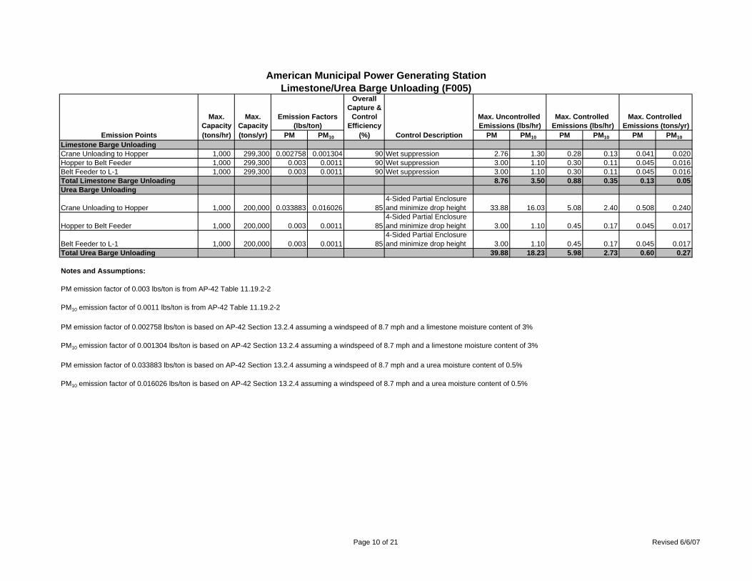
American Municipal Power Generating StationLimestone/Urea Barge Unloading (F005)
OverallCapture &
Max. Max. Emission Factors Control Max. Uncontrolled Max. Controlled Max. Controlled Capacity Capacity (lbs/ton) Efficiency Emissions (lbs/hr) Emissions (lbs/hr) Emissions (tons/yr)
Emission Points (tons/hr) (tons/yr) PM PM10 (%) Control Description PM PM10 PM PM10 PM PM10Limestone Barge UnloadingCrane Unloading to Hopper 1,000 299,300 0.002758 0.001304 90 Wet suppression 2.76 1.30 0.28 0.13 0.041 0.020Hopper to Belt Feeder 1,000 299,300 0.003 0.0011 90 Wet suppression 3.00 1.10 0.30 0.11 0.045 0.016Belt Feeder to L-1 1,000 299,300 0.003 0.0011 90 Wet suppression 3.00 1.10 0.30 0.11 0.045 0.016Total Limestone Barge Unloading 8.76 3.50 0.88 0.35 0.13 0.05Urea Barge Unloading
Crane Unloading to Hopper 1,000 200,000 0.033883 0.016026 854-Sided Partial Enclosure and minimize drop height 33.88 16.03 5.08 2.40 0.508 0.240
Hopper to Belt Feeder 1,000 200,000 0.003 0.0011 854-Sided Partial Enclosure and minimize drop height 3.00 1.10 0.45 0.17 0.045 0.017
Belt Feeder to L-1 1,000 200,000 0.003 0.0011 854-Sided Partial Enclosure and minimize drop height 3.00 1.10 0.45 0.17 0.045 0.017
Total Urea Barge Unloading 39.88 18.23 5.98 2.73 0.60 0.27
Notes and Assumptions:
PM emission factor of 0.003 lbs/ton is from AP-42 Table 11.19.2-2
PM10 emission factor of 0.0011 lbs/ton is from AP-42 Table 11.19.2-2
PM emission factor of 0.002758 lbs/ton is based on AP-42 Section 13.2.4 assuming a windspeed of 8.7 mph and a limestone moisture content of 3%
PM10 emission factor of 0.001304 lbs/ton is based on AP-42 Section 13.2.4 assuming a windspeed of 8.7 mph and a limestone moisture content of 3%
PM emission factor of 0.033883 lbs/ton is based on AP-42 Section 13.2.4 assuming a windspeed of 8.7 mph and a urea moisture content of 0.5%
PM10 emission factor of 0.016026 lbs/ton is based on AP-42 Section 13.2.4 assuming a windspeed of 8.7 mph and a urea moisture content of 0.5%
Page 10 of 21 Revised 6/6/07
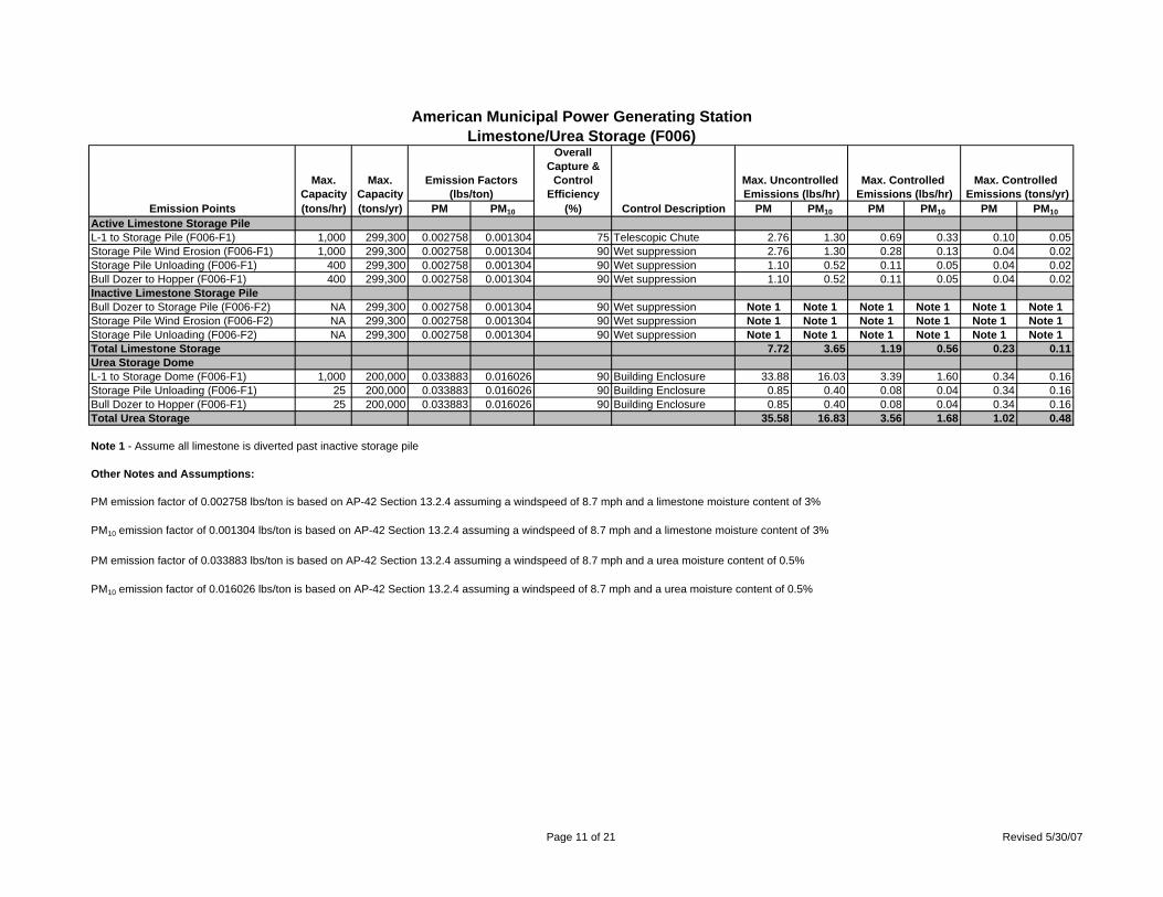
American Municipal Power Generating StationLimestone/Urea Storage (F006)
OverallCapture &
Max. Max. Emission Factors Control Max. Uncontrolled Max. Controlled Max. Controlled Capacity Capacity (lbs/ton) Efficiency Emissions (lbs/hr) Emissions (lbs/hr) Emissions (tons/yr)
Emission Points (tons/hr) (tons/yr) PM PM10 (%) Control Description PM PM10 PM PM10 PM PM10Active Limestone Storage PileL-1 to Storage Pile (F006-F1) 1,000 299,300 0.002758 0.001304 75 Telescopic Chute 2.76 1.30 0.69 0.33 0.10 0.05Storage Pile Wind Erosion (F006-F1) 1,000 299,300 0.002758 0.001304 90 Wet suppression 2.76 1.30 0.28 0.13 0.04 0.02Storage Pile Unloading (F006-F1) 400 299,300 0.002758 0.001304 90 Wet suppression 1.10 0.52 0.11 0.05 0.04 0.02Bull Dozer to Hopper (F006-F1) 400 299,300 0.002758 0.001304 90 Wet suppression 1.10 0.52 0.11 0.05 0.04 0.02Inactive Limestone Storage PileBull Dozer to Storage Pile (F006-F2) NA 299,300 0.002758 0.001304 90 Wet suppression Note 1 Note 1 Note 1 Note 1 Note 1 Note 1Storage Pile Wind Erosion (F006-F2) NA 299,300 0.002758 0.001304 90 Wet suppression Note 1 Note 1 Note 1 Note 1 Note 1 Note 1Storage Pile Unloading (F006-F2) NA 299,300 0.002758 0.001304 90 Wet suppression Note 1 Note 1 Note 1 Note 1 Note 1 Note 1Total Limestone Storage 7.72 3.65 1.19 0.56 0.23 0.11Urea Storage DomeL-1 to Storage Dome (F006-F1) 1,000 200,000 0.033883 0.016026 90 Building Enclosure 33.88 16.03 3.39 1.60 0.34 0.16Storage Pile Unloading (F006-F1) 25 200,000 0.033883 0.016026 90 Building Enclosure 0.85 0.40 0.08 0.04 0.34 0.16Bull Dozer to Hopper (F006-F1) 25 200,000 0.033883 0.016026 90 Building Enclosure 0.85 0.40 0.08 0.04 0.34 0.16Total Urea Storage 35.58 16.83 3.56 1.68 1.02 0.48
Note 1 - Assume all limestone is diverted past inactive storage pile
Other Notes and Assumptions:
PM emission factor of 0.002758 lbs/ton is based on AP-42 Section 13.2.4 assuming a windspeed of 8.7 mph and a limestone moisture content of 3%
PM10 emission factor of 0.001304 lbs/ton is based on AP-42 Section 13.2.4 assuming a windspeed of 8.7 mph and a limestone moisture content of 3%
PM emission factor of 0.033883 lbs/ton is based on AP-42 Section 13.2.4 assuming a windspeed of 8.7 mph and a urea moisture content of 0.5%
PM10 emission factor of 0.016026 lbs/ton is based on AP-42 Section 13.2.4 assuming a windspeed of 8.7 mph and a urea moisture content of 0.5%
Page 11 of 21 Revised 5/30/07
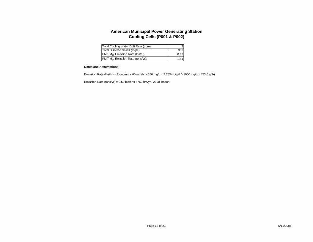
American Municipal Power Generating StationCooling Cells (P001 & P002)
Total Cooling Water Drift Rate (gpm) 2Total Disolved Solids (mg/L): 350PM/PM10 Emission Rate (lbs/hr): 0.35PM/PM10 Emission Rate (tons/yr): 1.54
Notes and Assumptions:
Emission Rate (lbs/hr) = 2 gal/min x 60 min/hr x 350 mg/L x 3.7854 L/gal / (1000 mg/g x 453.6 g/lb)
Emission Rate (tons/yr) = 0.50 lbs/hr x 8760 hrs/yr / 2000 lbs/ton
Page 12 of 21 5/11/2006
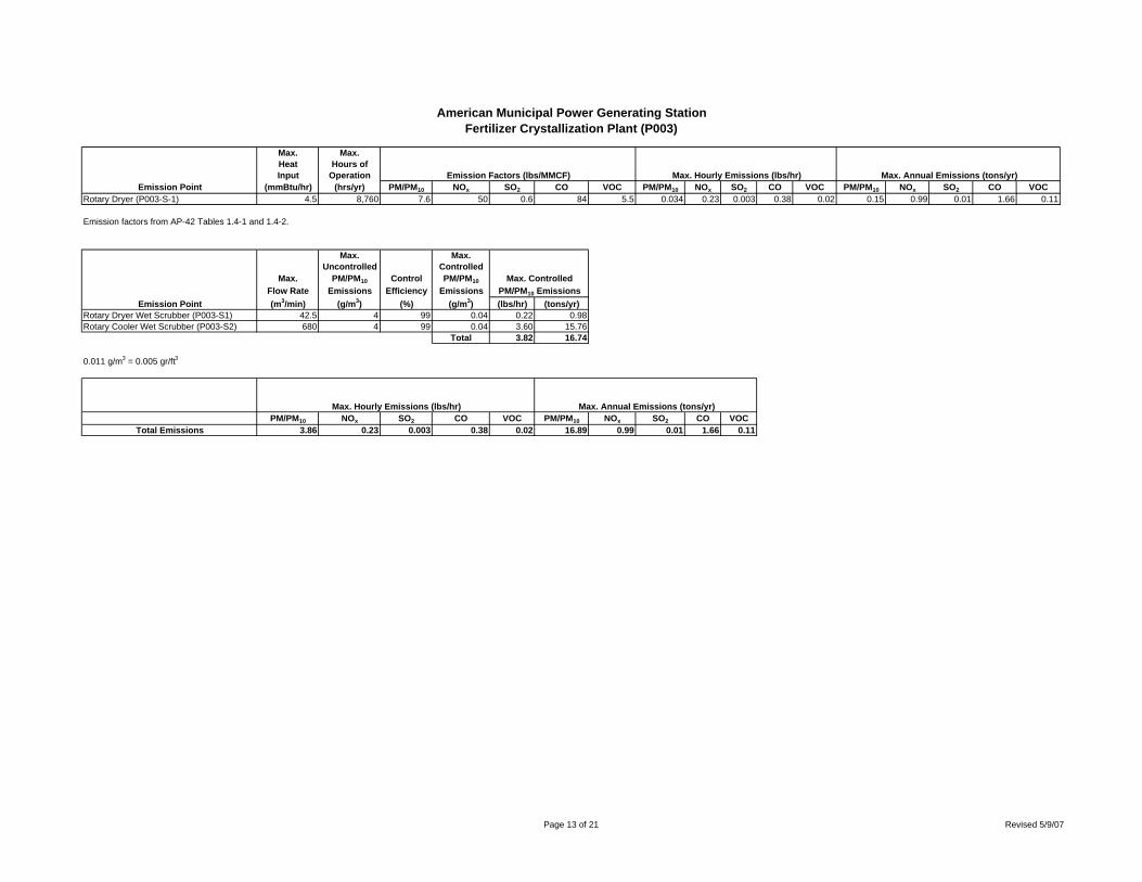
American Municipal Power Generating StationFertilizer Crystallization Plant (P003)
Max. Max.Heat Hours ofInput Operation Emission Factors (lbs/MMCF) Max. Hourly Emissions (lbs/hr) Max. Annual Emissions (tons/yr)
Emission Point (mmBtu/hr) (hrs/yr) PM/PM10 NOx SO2 CO VOC PM/PM10 NOx SO2 CO VOC PM/PM10 NOx SO2 CO VOCRotary Dryer (P003-S-1) 4.5 8,760 7.6 50 0.6 84 5.5 0.034 0.23 0.003 0.38 0.02 0.15 0.99 0.01 1.66 0.11
Emission factors from AP-42 Tables 1.4-1 and 1.4-2.
Max. Max.Uncontrolled Controlled
Max. PM/PM10 Control PM/PM10 Max. ControlledFlow Rate Emissions Efficiency Emissions PM/PM10 Emissions
Emission Point (m3/min) (g/m3) (%) (g/m3) (lbs/hr) (tons/yr)Rotary Dryer Wet Scrubber (P003-S1) 42.5 4 99 0.04 0.22 0.98Rotary Cooler Wet Scrubber (P003-S2) 680 4 99 0.04 3.60 15.76
Total 3.82 16.74
0.011 g/m3 = 0.005 gr/ft3
Max. Hourly Emissions (lbs/hr) Max. Annual Emissions (tons/yr)PM/PM10 NOx SO2 CO VOC PM/PM10 NOx SO2 CO VOC
Total Emissions 3.86 0.23 0.003 0.38 0.02 16.89 0.99 0.01 1.66 0.11
Page 13 of 21 Revised 5/9/07
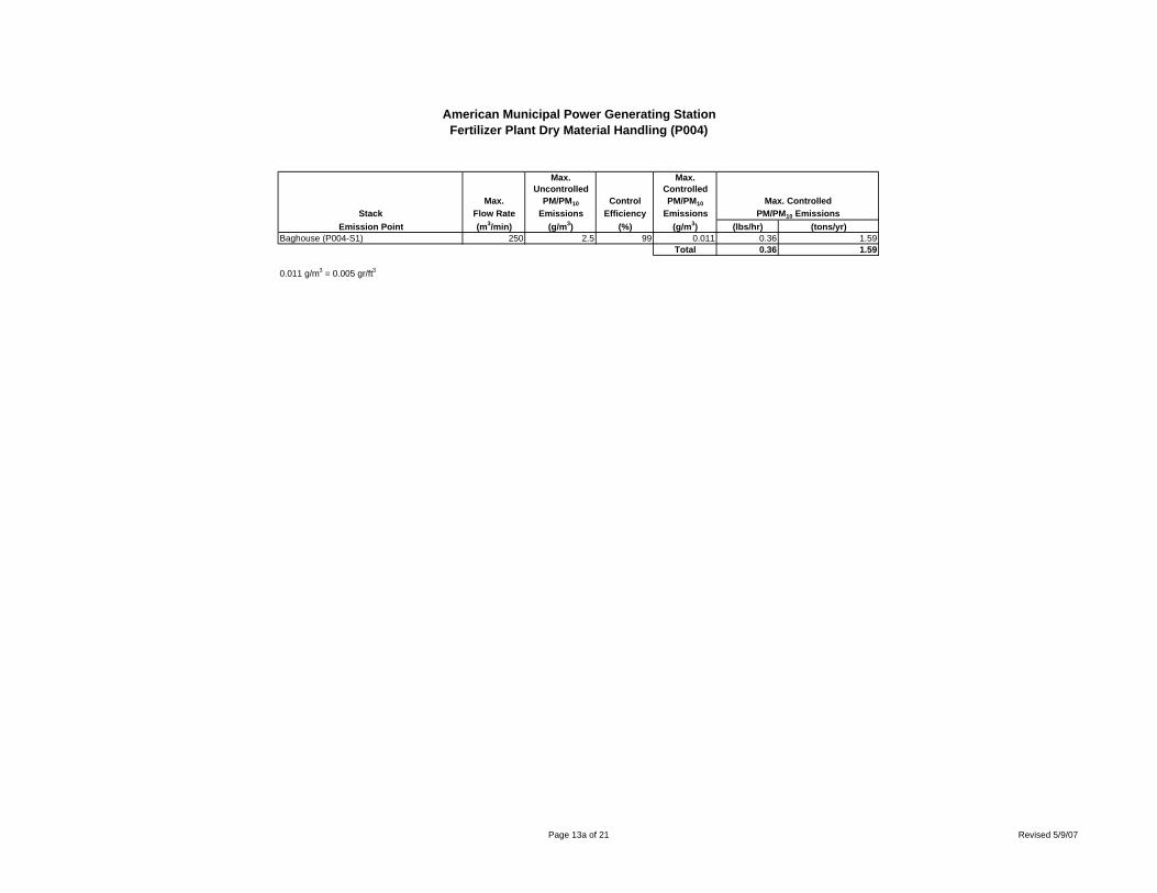
American Municipal Power Generating StationFertilizer Plant Dry Material Handling (P004)
Max. Max.Uncontrolled Controlled
Max. PM/PM10 Control PM/PM10 Max. ControlledStack Flow Rate Emissions Efficiency Emissions PM/PM10 Emissions
Emission Point (m3/min) (g/m3) (%) (g/m3) (lbs/hr) (tons/yr)Baghouse (P004-S1) 250 2.5 99 0.011 0.36 1.59
Total 0.36 1.59
0.011 g/m3 = 0.005 gr/ft3
Page 13a of 21 Revised 5/9/07
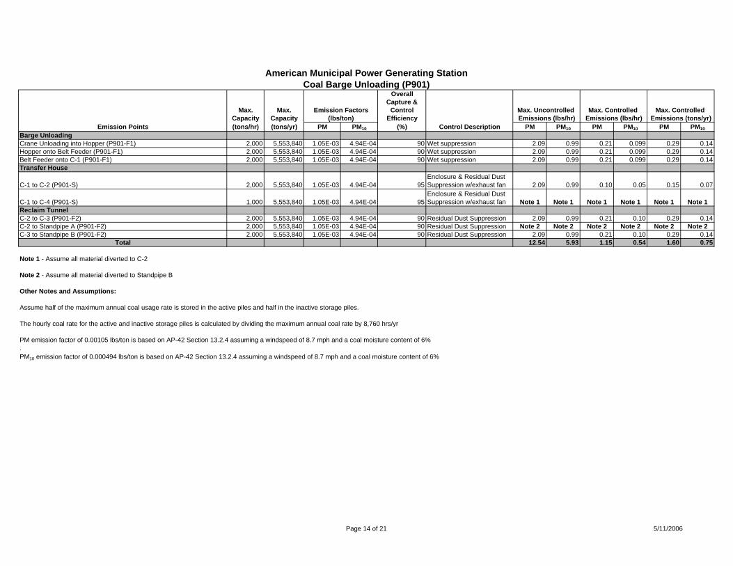
American Municipal Power Generating StationCoal Barge Unloading (P901)
OverallCapture &
Max. Max. Emission Factors Control Max. Uncontrolled Max. Controlled Max. Controlled Capacity Capacity (lbs/ton) Efficiency Emissions (lbs/hr) Emissions (lbs/hr) Emissions (tons/yr)
Emission Points (tons/hr) (tons/yr) PM PM10 (%) Control Description PM PM10 PM PM10 PM PM10Barge UnloadingCrane Unloading into Hopper (P901-F1) 2,000 5,553,840 1.05E-03 4.94E-04 90 Wet suppression 2.09 0.99 0.21 0.099 0.29 0.14Hopper onto Belt Feeder (P901-F1) 2,000 5,553,840 1.05E-03 4.94E-04 90 Wet suppression 2.09 0.99 0.21 0.099 0.29 0.14Belt Feeder onto C-1 (P901-F1) 2,000 5,553,840 1.05E-03 4.94E-04 90 Wet suppression 2.09 0.99 0.21 0.099 0.29 0.14Transfer House
C-1 to C-2 (P901-S) 2,000 5,553,840 1.05E-03 4.94E-04 95Enclosure & Residual Dust Suppression w/exhaust fan 2.09 0.99 0.10 0.05 0.15 0.07
C-1 to C-4 (P901-S) 1,000 5,553,840 1.05E-03 4.94E-04 95Enclosure & Residual Dust Suppression w/exhaust fan Note 1 Note 1 Note 1 Note 1 Note 1 Note 1
Reclaim TunnelC-2 to C-3 (P901-F2) 2,000 5,553,840 1.05E-03 4.94E-04 90 Residual Dust Suppression 2.09 0.99 0.21 0.10 0.29 0.14C-2 to Standpipe A (P901-F2) 2,000 5,553,840 1.05E-03 4.94E-04 90 Residual Dust Suppression Note 2 Note 2 Note 2 Note 2 Note 2 Note 2C-3 to Standpipe B (P901-F2) 2,000 5,553,840 1.05E-03 4.94E-04 90 Residual Dust Suppression 2.09 0.99 0.21 0.10 0.29 0.14
Total 12.54 5.93 1.15 0.54 1.60 0.75
Note 1 - Assume all material diverted to C-2
Note 2 - Assume all material diverted to Standpipe B
Other Notes and Assumptions:
Assume half of the maximum annual coal usage rate is stored in the active piles and half in the inactive storage piles.
The hourly coal rate for the active and inactive storage piles is calculated by dividing the maximum annual coal rate by 8,760 hrs/yr
PM emission factor of 0.00105 lbs/ton is based on AP-42 Section 13.2.4 assuming a windspeed of 8.7 mph and a coal moisture content of 6%.PM10 emission factor of 0.000494 lbs/ton is based on AP-42 Section 13.2.4 assuming a windspeed of 8.7 mph and a coal moisture content of 6%
Page 14 of 21 5/11/2006
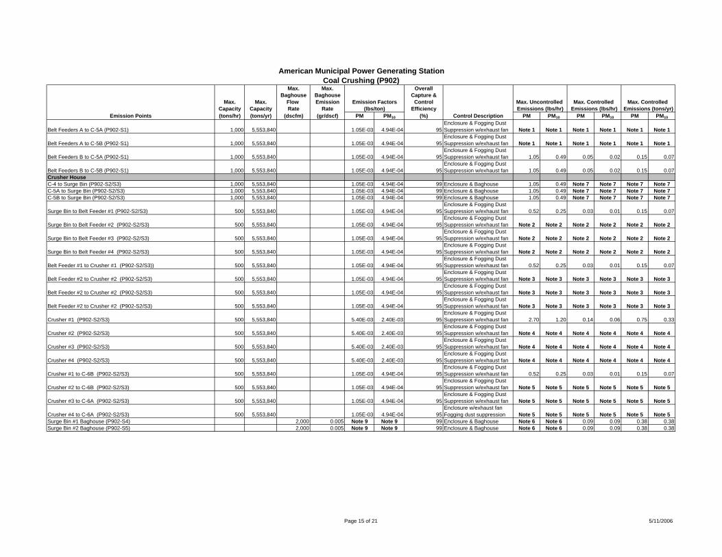
American Municipal Power Generating StationCoal Crushing (P902)
Max. Max. OverallBaghouse Baghouse Capture &
Max. Max. Flow Emission Emission Factors Control Max. Uncontrolled Max. Controlled Max. Controlled Capacity Capacity Rate Rate (lbs/ton) Efficiency Emissions (lbs/hr) Emissions (lbs/hr) Emissions (tons/yr)
Emission Points (tons/hr) (tons/yr) (dscfm) (gr/dscf) PM PM10 (%) Control Description PM PM10 PM PM10 PM PM10
Belt Feeders A to C-5A (P902-S1) 1,000 5,553,840 1.05E-03 4.94E-04 95Enclosure & Fogging Dust Suppression w/exhaust fan Note 1 Note 1 Note 1 Note 1 Note 1 Note 1
Belt Feeders A to C-5B (P902-S1) 1,000 5,553,840 1.05E-03 4.94E-04 95Enclosure & Fogging Dust Suppression w/exhaust fan Note 1 Note 1 Note 1 Note 1 Note 1 Note 1
Belt Feeders B to C-5A (P902-S1) 1,000 5,553,840 1.05E-03 4.94E-04 95Enclosure & Fogging Dust Suppression w/exhaust fan 1.05 0.49 0.05 0.02 0.15 0.07
Belt Feeders B to C-5B (P902-S1) 1,000 5,553,840 1.05E-03 4.94E-04 95Enclosure & Fogging Dust Suppression w/exhaust fan 1.05 0.49 0.05 0.02 0.15 0.07
Crusher HouseC-4 to Surge Bin (P902-S2/S3) 1,000 5,553,840 1.05E-03 4.94E-04 99 Enclosure & Baghouse 1.05 0.49 Note 7 Note 7 Note 7 Note 7C-5A to Surge Bin (P902-S2/S3) 1,000 5,553,840 1.05E-03 4.94E-04 99 Enclosure & Baghouse 1.05 0.49 Note 7 Note 7 Note 7 Note 7C-5B to Surge Bin (P902-S2/S3) 1,000 5,553,840 1.05E-03 4.94E-04 99 Enclosure & Baghouse 1.05 0.49 Note 7 Note 7 Note 7 Note 7
Surge Bin to Belt Feeder #1 (P902-S2/S3) 500 5,553,840 1.05E-03 4.94E-04 95Enclosure & Fogging Dust Suppression w/exhaust fan 0.52 0.25 0.03 0.01 0.15 0.07
Surge Bin to Belt Feeder #2 (P902-S2/S3) 500 5,553,840 1.05E-03 4.94E-04 95Enclosure & Fogging Dust Suppression w/exhaust fan Note 2 Note 2 Note 2 Note 2 Note 2 Note 2
Surge Bin to Belt Feeder #3 (P902-S2/S3) 500 5,553,840 1.05E-03 4.94E-04 95Enclosure & Fogging Dust Suppression w/exhaust fan Note 2 Note 2 Note 2 Note 2 Note 2 Note 2
Surge Bin to Belt Feeder #4 (P902-S2/S3) 500 5,553,840 1.05E-03 4.94E-04 95Enclosure & Fogging Dust Suppression w/exhaust fan Note 2 Note 2 Note 2 Note 2 Note 2 Note 2
Belt Feeder #1 to Crusher #1 (P902-S2/S3)) 500 5,553,840 1.05E-03 4.94E-04 95Enclosure & Fogging Dust Suppression w/exhaust fan 0.52 0.25 0.03 0.01 0.15 0.07
Belt Feeder #2 to Crusher #2 (P902-S2/S3) 500 5,553,840 1.05E-03 4.94E-04 95Enclosure & Fogging Dust Suppression w/exhaust fan Note 3 Note 3 Note 3 Note 3 Note 3 Note 3
Belt Feeder #2 to Crusher #2 (P902-S2/S3) 500 5,553,840 1.05E-03 4.94E-04 95Enclosure & Fogging Dust Suppression w/exhaust fan Note 3 Note 3 Note 3 Note 3 Note 3 Note 3
Belt Feeder #2 to Crusher #2 (P902-S2/S3) 500 5,553,840 1.05E-03 4.94E-04 95Enclosure & Fogging Dust Suppression w/exhaust fan Note 3 Note 3 Note 3 Note 3 Note 3 Note 3
Crusher #1 (P902-S2/S3) 500 5,553,840 5.40E-03 2.40E-03 95Enclosure & Fogging Dust Suppression w/exhaust fan 2.70 1.20 0.14 0.06 0.75 0.33
Crusher #2 (P902-S2/S3) 500 5,553,840 5.40E-03 2.40E-03 95Enclosure & Fogging Dust Suppression w/exhaust fan Note 4 Note 4 Note 4 Note 4 Note 4 Note 4
Crusher #3 (P902-S2/S3) 500 5,553,840 5.40E-03 2.40E-03 95Enclosure & Fogging Dust Suppression w/exhaust fan Note 4 Note 4 Note 4 Note 4 Note 4 Note 4
Crusher #4 (P902-S2/S3) 500 5,553,840 5.40E-03 2.40E-03 95Enclosure & Fogging Dust Suppression w/exhaust fan Note 4 Note 4 Note 4 Note 4 Note 4 Note 4
Crusher #1 to C-6B (P902-S2/S3) 500 5,553,840 1.05E-03 4.94E-04 95Enclosure & Fogging Dust Suppression w/exhaust fan 0.52 0.25 0.03 0.01 0.15 0.07
Crusher #2 to C-6B (P902-S2/S3) 500 5,553,840 1.05E-03 4.94E-04 95Enclosure & Fogging Dust Suppression w/exhaust fan Note 5 Note 5 Note 5 Note 5 Note 5 Note 5
Crusher #3 to C-6A (P902-S2/S3) 500 5,553,840 1.05E-03 4.94E-04 95Enclosure & Fogging Dust Suppression w/exhaust fan Note 5 Note 5 Note 5 Note 5 Note 5 Note 5
Crusher #4 to C-6A (P902-S2/S3) 500 5,553,840 1.05E-03 4.94E-04 95Enclosure w/exhaust fanFogging dust suppression Note 5 Note 5 Note 5 Note 5 Note 5 Note 5
Surge Bin #1 Baghouse (P902-S4) 2,000 0.005 Note 9 Note 9 99 Enclosure & Baghouse Note 6 Note 6 0.09 0.09 0.38 0.38Surge Bin #2 Baghouse (P902-S5) 2,000 0.005 Note 9 Note 9 99 Enclosure & Baghouse Note 6 Note 6 0.09 0.09 0.38 0.38
Page 15 of 21 5/11/2006
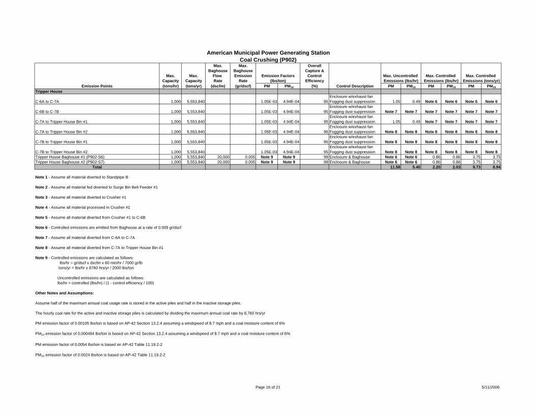
American Municipal Power Generating StationCoal Crushing (P902)
Max. Max. OverallBaghouse Baghouse Capture &
Max. Max. Flow Emission Emission Factors Control Max. Uncontrolled Max. Controlled Max. Controlled Capacity Capacity Rate Rate (lbs/ton) Efficiency Emissions (lbs/hr) Emissions (lbs/hr) Emissions (tons/yr)
Emission Points (tons/hr) (tons/yr) (dscfm) (gr/dscf) PM PM10 (%) Control Description PM PM10 PM PM10 PM PM10Tripper House
C-6A to C-7A 1,000 5,553,840 1.05E-03 4.94E-04 95Enclosure w/exhaust fanFogging dust suppression 1.05 0.49 Note 6 Note 6 Note 6 Note 6
C-6B to C-7B 1,000 5,553,840 1.05E-03 4.94E-04 95Enclosure w/exhaust fanFogging dust suppression Note 7 Note 7 Note 7 Note 7 Note 7 Note 7
C-7A to Tripper House Bin #1 1,000 5,553,840 1.05E-03 4.94E-04 95Enclosure w/exhaust fanFogging dust suppression 1.05 0.49 Note 7 Note 7 Note 7 Note 7
C-7A to Tripper House Bin #2 1,000 5,553,840 1.05E-03 4.94E-04 95Enclosure w/exhaust fanFogging dust suppression Note 8 Note 8 Note 8 Note 8 Note 8 Note 8
C-7B to Tripper House Bin #1 1,000 5,553,840 1.05E-03 4.94E-04 95Enclosure w/exhaust fanFogging dust suppression Note 8 Note 8 Note 8 Note 8 Note 8 Note 8
C-7B to Tripper House Bin #2 1,000 5,553,840 1.05E-03 4.94E-04 95Enclosure w/exhaust fanFogging dust suppression Note 8 Note 8 Note 8 Note 8 Note 8 Note 8
Tripper House Baghouse #1 (P902-S6) 1,000 5,553,840 20,000 0.005 Note 9 Note 9 99 Enclosure & Baghouse Note 6 Note 6 0.86 0.86 3.75 3.75Tripper House Baghouse #2 (P902-S7) 1,000 5,553,840 20,000 0.005 Note 9 Note 9 99 Enclosure & Baghouse Note 6 Note 6 0.86 0.86 3.75 3.75
Total 11.58 5.40 2.20 2.03 9.73 8.94
Note 1 - Assume all material diverted to Standpipe B
Note 2 - Assume all material fed diverted to Surge Bin Belt Feeder #1
Note 3 - Assume all material diverted to Crusher #1
Note 4 - Assume all material processed in Crusher #1
Note 5 - Assume all material diverted from Crusher #1 to C-6B
Note 6 - Controlled emissions are emitted from Baghouse at a rate of 0.005 gr/dscf
Note 7 - Assume all material diverted from C-6A to C-7A
Note 8 - Assume all material diverted from C-7A to Tripper House Bin #1
Note 9 - Controlled emissions are calculated as follows: lbs/hr = gr/dscf x dscfm x 60 min/hr / 7000 gr/lb tons/yr = lbs/hr x 8760 hrs/yr / 2000 lbs/ton
Uncontrolled emissions are calculated as follows: lbs/hr = controlled (lbs/hr) / (1 - control efficiency / 100)
Other Notes and Assumptions:
Assume half of the maximum annual coal usage rate is stored in the active piles and half in the inactive storage piles.
The hourly coal rate for the active and inactive storage piles is calculated by dividing the maximum annual coal rate by 8,760 hrs/yr
PM emission factor of 0.00105 lbs/ton is based on AP-42 Section 13.2.4 assuming a windspeed of 8.7 mph and a coal moisture content of 6%.PM10 emission factor of 0.000494 lbs/ton is based on AP-42 Section 13.2.4 assuming a windspeed of 8.7 mph and a coal moisture content of 6%
PM emission factor of 0.0054 lbs/ton is based on AP-42 Table 11.19.2-2
PM10 emission factor of 0.0024 lbs/ton is based on AP-42 Table 11.19.2-2
Page 16 of 21 5/11/2006
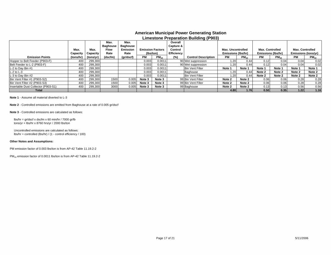
American Municipal Power Generating StationLimestone Preparation Building (P903)
Max. Max. OverallBaghouse Baghouse Capture &
Max. Max. Flow Emission Emission Factors Control Max. Uncontrolled Max. Controlled Max. Controlled Capacity Capacity Rate Rate (lbs/ton) Efficiency Emissions (lbs/hr) Emissions (lbs/hr) Emissions (tons/yr)
Emission Points (tons/hr) (tons/yr) (dscfm) (gr/dscf) PM PM10 (%) Control Description PM PM10 PM PM10 PM PM10Hopper to Belt Feeder (P903-F) 400 299,300 0.003 0.0011 90 Wet suppression 1.20 0.44 0.12 0.04 0.04 0.02Belt Feeder to L-2 (P903-F) 400 299,300 0.003 0.0011 90 Wet suppression 1.20 0.44 0.12 0.04 0.04 0.02L-2 to Day Bin #1 400 299,300 0.003 0.0011 Bin Vent Filter Note 1 Note 1 Note 1 Note 1 Note 1 Note 1L-2 to L-3 400 299,300 0.003 0.0011 Baghouse 1.20 0.44 Note 2 Note 2 Note 2 Note 2L-3 to Day Bin #2 400 299,300 0.003 0.0011 Bin Vent Filter 1.20 0.44 Note 2 Note 2 Note 2 Note 2Bin Vent Filter #1 (P903-S2) 400 299,300 1500 0.005 Note 3 Note 3 99 Bin Vent Filter Note 2 Note 2 0.06 0.06 0.28 0.28Bin Vent Filter #2 (P903-S3) 400 299,300 1500 0.005 Note 3 Note 3 99 Bin Vent Filter Note 2 Note 2 0.06 0.06 0.28 0.28Insertable Dust Collector (P903-S1) 400 299,300 3000 0.005 Note 3 Note 3 99 Baghouse Note 2 Note 2 0.13 0.13 0.56 0.56
Total 4.80 1.76 0.50 0.35 1.22 1.16
Note 1 - Assume all material diverted to L-3
Note 2 - Controlled emissions are emitted from Baghouse at a rate of 0.005 gr/dscf
Note 3 - Controlled emissions are calculated as follows:
lbs/hr = gr/dscf x dscfm x 60 min/hr / 7000 gr/lb tons/yr = lbs/hr x 8760 hrs/yr / 2000 lbs/ton
Uncontrolled emissions are calculated as follows: lbs/hr = controlled (lbs/hr) / (1 - control efficiency / 100)
Other Notes and Assumptions:
PM emission factor of 0.003 lbs/ton is from AP-42 Table 11.19.2-2
PM10 emission factor of 0.0011 lbs/ton is from AP-42 Table 11.19.2-2
Page 17 of 21 5/11/2006
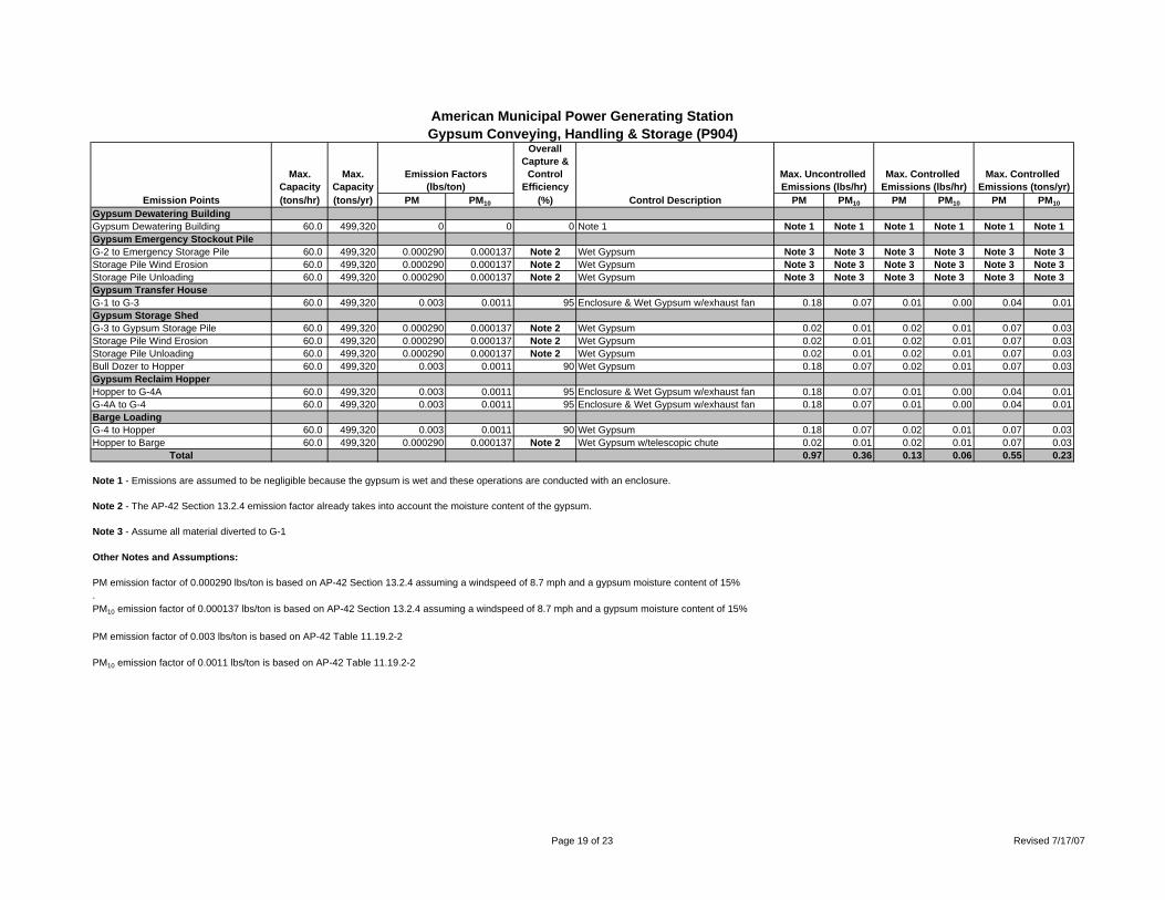
American Municipal Power Generating StationGypsum Conveying, Handling & Storage (P904)
OverallCapture &
Max. Max. Emission Factors Control Max. Uncontrolled Max. Controlled Max. Controlled Capacity Capacity (lbs/ton) Efficiency Emissions (lbs/hr) Emissions (lbs/hr) Emissions (tons/yr)
Emission Points (tons/hr) (tons/yr) PM PM10 (%) Control Description PM PM10 PM PM10 PM PM10
Gypsum Dewatering BuildingGypsum Dewatering Building 60.0 499,320 0 0 0 Note 1 Note 1 Note 1 Note 1 Note 1 Note 1 Note 1Gypsum Emergency Stockout PileG-2 to Emergency Storage Pile 60.0 499,320 0.000290 0.000137 Note 2 Wet Gypsum Note 3 Note 3 Note 3 Note 3 Note 3 Note 3Storage Pile Wind Erosion 60.0 499,320 0.000290 0.000137 Note 2 Wet Gypsum Note 3 Note 3 Note 3 Note 3 Note 3 Note 3Storage Pile Unloading 60.0 499,320 0.000290 0.000137 Note 2 Wet Gypsum Note 3 Note 3 Note 3 Note 3 Note 3 Note 3Gypsum Transfer HouseG-1 to G-3 60.0 499,320 0.003 0.0011 95 Enclosure & Wet Gypsum w/exhaust fan 0.18 0.07 0.01 0.00 0.04 0.01Gypsum Storage ShedG-3 to Gypsum Storage Pile 60.0 499,320 0.000290 0.000137 Note 2 Wet Gypsum 0.02 0.01 0.02 0.01 0.07 0.03Storage Pile Wind Erosion 60.0 499,320 0.000290 0.000137 Note 2 Wet Gypsum 0.02 0.01 0.02 0.01 0.07 0.03Storage Pile Unloading 60.0 499,320 0.000290 0.000137 Note 2 Wet Gypsum 0.02 0.01 0.02 0.01 0.07 0.03Bull Dozer to Hopper 60.0 499,320 0.003 0.0011 90 Wet Gypsum 0.18 0.07 0.02 0.01 0.07 0.03Gypsum Reclaim HopperHopper to G-4A 60.0 499,320 0.003 0.0011 95 Enclosure & Wet Gypsum w/exhaust fan 0.18 0.07 0.01 0.00 0.04 0.01G-4A to G-4 60.0 499,320 0.003 0.0011 95 Enclosure & Wet Gypsum w/exhaust fan 0.18 0.07 0.01 0.00 0.04 0.01Barge LoadingG-4 to Hopper 60.0 499,320 0.003 0.0011 90 Wet Gypsum 0.18 0.07 0.02 0.01 0.07 0.03Hopper to Barge 60.0 499,320 0.000290 0.000137 Note 2 Wet Gypsum w/telescopic chute 0.02 0.01 0.02 0.01 0.07 0.03
Total 0.97 0.36 0.13 0.06 0.55 0.23
Note 1 - Emissions are assumed to be negligible because the gypsum is wet and these operations are conducted with an enclosure.
Note 2 - The AP-42 Section 13.2.4 emission factor already takes into account the moisture content of the gypsum.
Note 3 - Assume all material diverted to G-1
Other Notes and Assumptions:
PM emission factor of 0.000290 lbs/ton is based on AP-42 Section 13.2.4 assuming a windspeed of 8.7 mph and a gypsum moisture content of 15%.PM10 emission factor of 0.000137 lbs/ton is based on AP-42 Section 13.2.4 assuming a windspeed of 8.7 mph and a gypsum moisture content of 15%
PM emission factor of 0.003 lbs/ton is based on AP-42 Table 11.19.2-2
PM10 emission factor of 0.0011 lbs/ton is based on AP-42 Table 11.19.2-2
Page 19 of 23 Revised 7/17/07
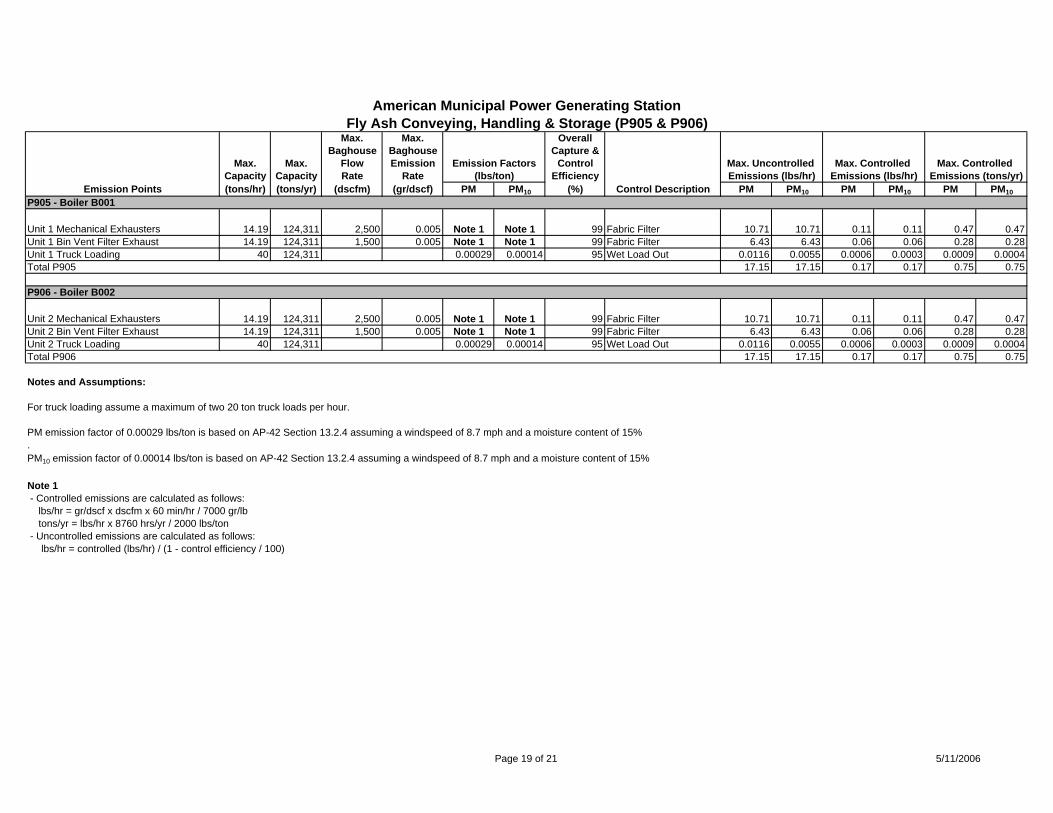
American Municipal Power Generating StationFly Ash Conveying, Handling & Storage (P905 & P906)
Max. Max. OverallBaghouse Baghouse Capture &
Max. Max. Flow Emission Emission Factors Control Max. Uncontrolled Max. Controlled Max. Controlled Capacity Capacity Rate Rate (lbs/ton) Efficiency Emissions (lbs/hr) Emissions (lbs/hr) Emissions (tons/yr)
Emission Points (tons/hr) (tons/yr) (dscfm) (gr/dscf) PM PM10 (%) Control Description PM PM10 PM PM10 PM PM10P905 - Boiler B001
Unit 1 Mechanical Exhausters 14.19 124,311 2,500 0.005 Note 1 Note 1 99 Fabric Filter 10.71 10.71 0.11 0.11 0.47 0.47Unit 1 Bin Vent Filter Exhaust 14.19 124,311 1,500 0.005 Note 1 Note 1 99 Fabric Filter 6.43 6.43 0.06 0.06 0.28 0.28Unit 1 Truck Loading 40 124,311 0.00029 0.00014 95 Wet Load Out 0.0116 0.0055 0.0006 0.0003 0.0009 0.0004Total P905 17.15 17.15 0.17 0.17 0.75 0.75
P906 - Boiler B002
Unit 2 Mechanical Exhausters 14.19 124,311 2,500 0.005 Note 1 Note 1 99 Fabric Filter 10.71 10.71 0.11 0.11 0.47 0.47Unit 2 Bin Vent Filter Exhaust 14.19 124,311 1,500 0.005 Note 1 Note 1 99 Fabric Filter 6.43 6.43 0.06 0.06 0.28 0.28Unit 2 Truck Loading 40 124,311 0.00029 0.00014 95 Wet Load Out 0.0116 0.0055 0.0006 0.0003 0.0009 0.0004Total P906 17.15 17.15 0.17 0.17 0.75 0.75
Notes and Assumptions:
For truck loading assume a maximum of two 20 ton truck loads per hour.
PM emission factor of 0.00029 lbs/ton is based on AP-42 Section 13.2.4 assuming a windspeed of 8.7 mph and a moisture content of 15%.PM10 emission factor of 0.00014 lbs/ton is based on AP-42 Section 13.2.4 assuming a windspeed of 8.7 mph and a moisture content of 15%
Note 1 - Controlled emissions are calculated as follows: lbs/hr = gr/dscf x dscfm x 60 min/hr / 7000 gr/lb tons/yr = lbs/hr x 8760 hrs/yr / 2000 lbs/ton - Uncontrolled emissions are calculated as follows: lbs/hr = controlled (lbs/hr) / (1 - control efficiency / 100)
Page 19 of 21 5/11/2006
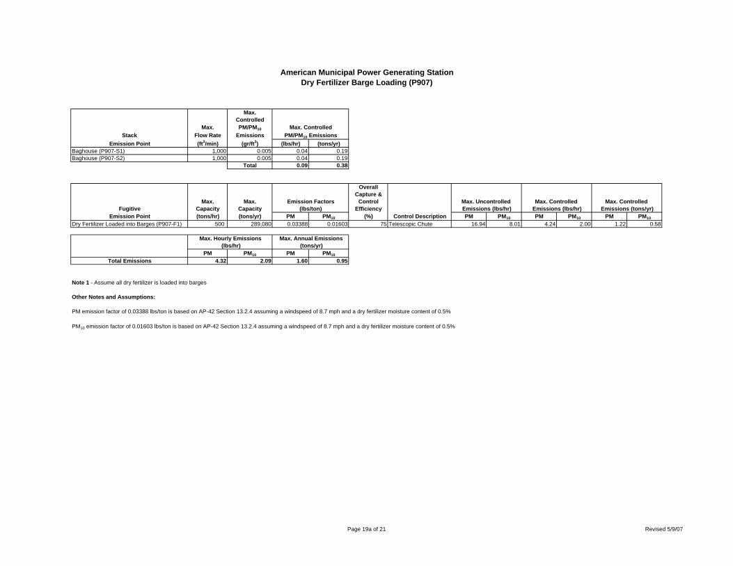
American Municipal Power Generating StationDry Fertilizer Barge Loading (P907)
Max.Controlled
Max. PM/PM10 Max. ControlledStack Flow Rate Emissions PM/PM10 Emissions
Emission Point (ft3/min) (gr/ft3) (lbs/hr) (tons/yr)Baghouse (P907-S1) 1,000 0.005 0.04 0.19Baghouse (P907-S2) 1,000 0.005 0.04 0.19
Total 0.09 0.38
OverallCapture &
Max. Max. Emission Factors Control Max. Uncontrolled Max. Controlled Max. Controlled Fugitive Capacity Capacity (lbs/ton) Efficiency Emissions (lbs/hr) Emissions (lbs/hr) Emissions (tons/yr)
Emission Point (tons/hr) (tons/yr) PM PM10 (%) Control Description PM PM10 PM PM10 PM PM10
Dry Fertilizer Loaded into Barges (P907-F1) 500 289,080 0.03388 0.01603 75 Telescopic Chute 16.94 8.01 4.24 2.00 1.22 0.58
Max. Hourly Emissions Max. Annual Emissions (lbs/hr) (tons/yr)
PM PM10 PM PM10
Total Emissions 4.32 2.09 1.60 0.95
Note 1 - Assume all dry fertilizer is loaded into barges
Other Notes and Assumptions:
PM emission factor of 0.03388 lbs/ton is based on AP-42 Section 13.2.4 assuming a windspeed of 8.7 mph and a dry fertilizer moisture content of 0.5%
PM10 emission factor of 0.01603 lbs/ton is based on AP-42 Section 13.2.4 assuming a windspeed of 8.7 mph and a dry fertilizer moisture content of 0.5%
Page 19a of 21 Revised 5/9/07
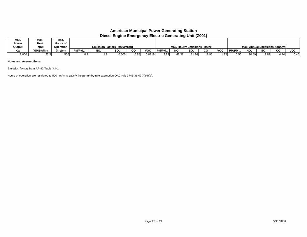
American Municipal Power Generating StationDiesel Engine Emergency Electric Generating Unit (Z001)
Max. Max. Max.Power Heat Hours ofOutput Input Operation Emission Factors (lbs/MMBtu) Max. Hourly Emissions (lbs/hr) Max. Annual Emissions (tons/yr)
Kw (MMBtu/hr) (hrs/yr) PM/PM10 NOx SO2 CO VOC PM/PM10 NOx SO2 CO VOC PM/PM10 NOx SO2 CO VOC2,000 22.3 500 0.1 1.9 0.505 0.85 0.0819 2.23 42.37 11.26 18.96 1.83 0.56 10.59 2.82 4.74 0.46
Notes and Assumptions:
Emission factors from AP-42 Table 3.4-1.
Hours of operation are restricted to 500 hrs/yr to satisfy the permit-by-rule exemption OAC rule 3745-31-03(A)(4)(a).
Page 20 of 21 5/11/2006
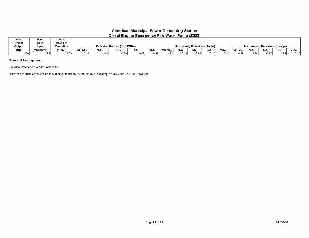
American Municipal Power Generating StationDiesel Engine Emergency Fire Water Pump (Z002)
Max. Max. Max.Power Heat Hours ofOutput Input Operation Emission Factors (lbs/MMBtu) Max. Hourly Emissions (lbs/hr) Max. Annual Emissions (tons/yr)
(Hp) (MMBtu/hr) (hrs/yr) PM/PM10 NOx SO2 CO VOC PM/PM10 NOx SO2 CO VOC PM/PM10 NOx SO2 CO VOC300 2.3 500 0.31 4.41 0.29 0.95 0.35 0.71 10.14 0.67 2.19 0.81 0.18 2.54 0.17 0.55 0.20
Notes and Assumptions:
Emission factors from AP-42 Table 3.3-1.
Hours of operation are restricted to 500 hrs/yr to satisfy the permit-by-rule exemption OAC rule 3745-31-03(A)(4)(a).
Page 21 of 21 5/11/2006