Embed Size (px)
Citation preview
1
Permanent Magnet Machines for Distributed Generation:A Review
Paper Number: 07GM0593
Authors:Tze-Fun Chan, EE Department,The Hong Kong Polytechnic University, Hong Kong, ChinaLoi Lei Lai, School of Engineering and Mathematical Sciences, City University, UK
2
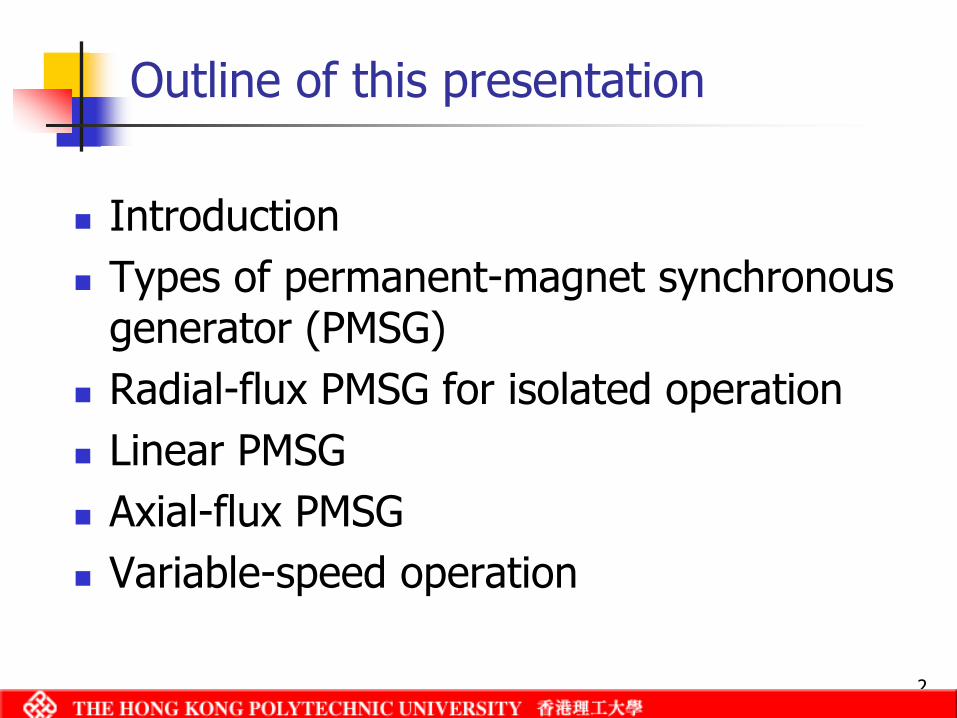
Outline of this presentation
IntroductionTypes of permanent-magnet synchronous generator (PMSG)Radial-flux PMSG for isolated operationLinear PMSGAxial-flux PMSGVariable-speed operation
3
Full exploitation of local energy resourcesAutonomous operation reduces the need for grid connection and transmission lossesImproves reliability /security of supplyGenerators types:
Induction generators Wound-field synchronous generatorsPM synchronous generatorsSwitched-reluctance generators
Advantages of distributed generation
4
Advantages and disadvantages of PMSG
Advantages:Brushless constructionLight weight amd small sizeHigh reliabilitryHigh efficiencyLess frequent maintenance
DisadvantagesExcitation is fixedOutput voltage varies with load
5
PM materials and PM machines
Types of PM material:Alnico (since 1940s)Ferrites (since 1950s)SmCo (since 1960s)NdFeB (since 1980s)
Types of PM machines:Surface magnet typeInterior magnet typeSurface inset type
6
Radial-flux PMSG for isolated operation
Research work:New machine configurations (Binns 1983)Performance analysis using 2-axis modelPerformance using finite element method (FEM) (Chen, Nayar and Xu,1998; Chan, Yan and Lai, 2004, 2005)Voltage regulation improvement by capacitor compensation (Rahman, 1996)Voltage regulation improvement by exploiting rotor inverse saliency
Interior type (Chalmers, 1994)Surface inset type (Chan, Yan and Lai, 2004)
7
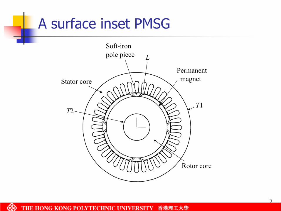
A surface inset PMSG
Stator core
Rotor core
Permanentmagnet
T2T1
LSoft-iron pole piece
8
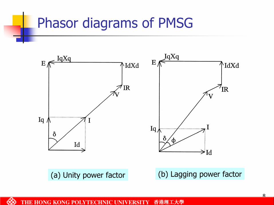
Phasor diagrams of PMSG
(a) Unity power factor (b) Lagging power factor
9
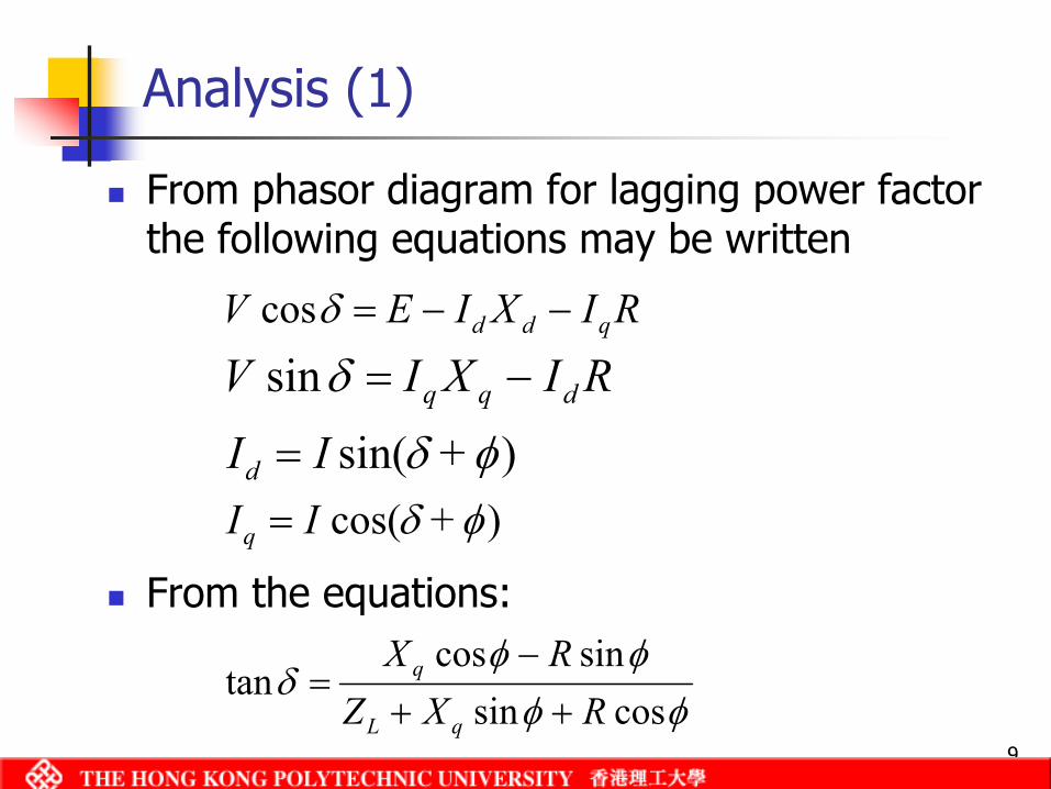
Analysis (1)
From phasor diagram for lagging power factor the following equations may be written
From the equations:
RIXI E V qdd −−=δcos
RIXI V dqq −=δsin)sin( φδ + IId =
)cos( φδ + IIq =
φφφφ
δcossin
sincostan
R XZ R X
qL
q
++−
=
10
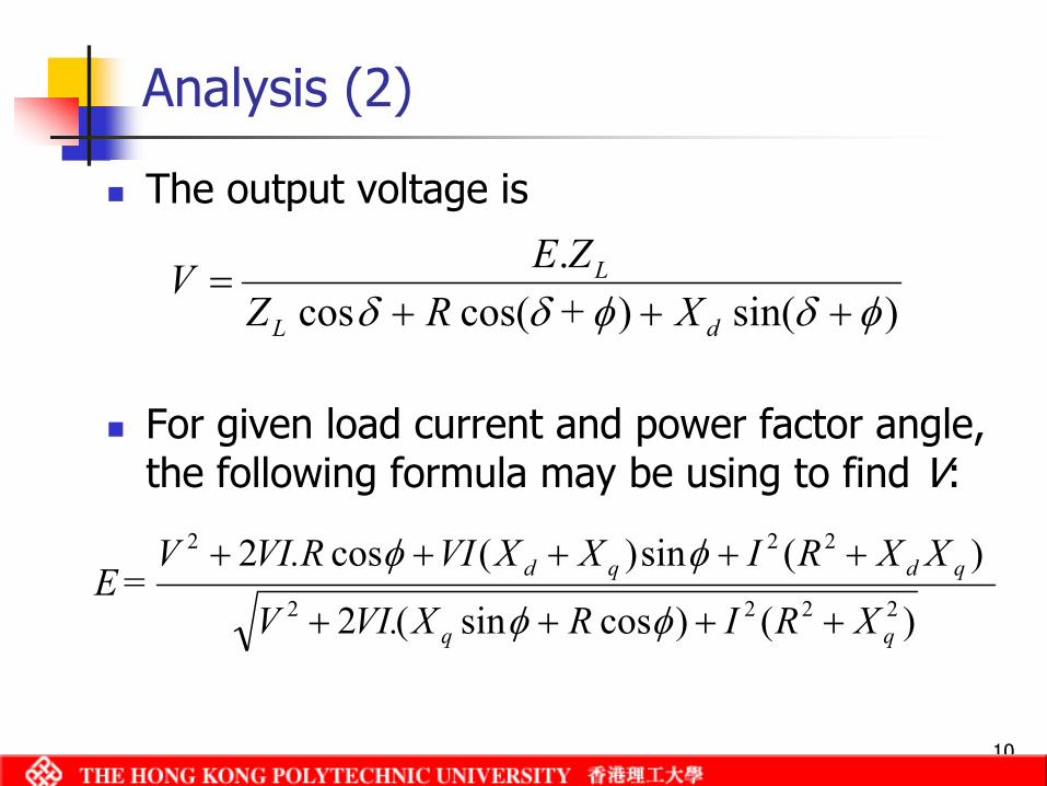
Analysis (2)
The output voltage is
For given load current and power factor angle, the following formula may be using to find V:
)sin()cos(cos.
φδφδδ X + R ZZE V
dL
L
+++=
)()cossin(2
)(sin)(cos22222
222
qdqd
XRI R XVI.V
XXRI XXVI VI.R V = E
++++
+++++
φφ
φφ
11
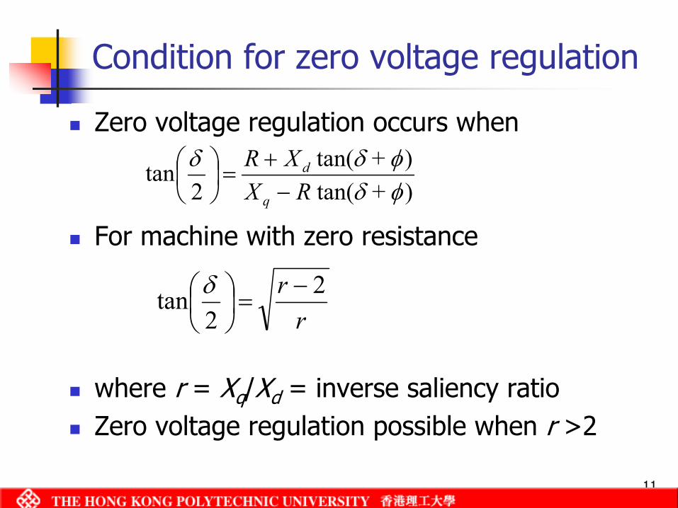
Condition for zero voltage regulation
Zero voltage regulation occurs when
For machine with zero resistance
where r = Xq/Xd = inverse saliency ratioZero voltage regulation possible when r >2
)tan()tan(
2tan
φδφδδ + RX
+XR q
d
−+
=
rr 2
2tan −
=
δ
12
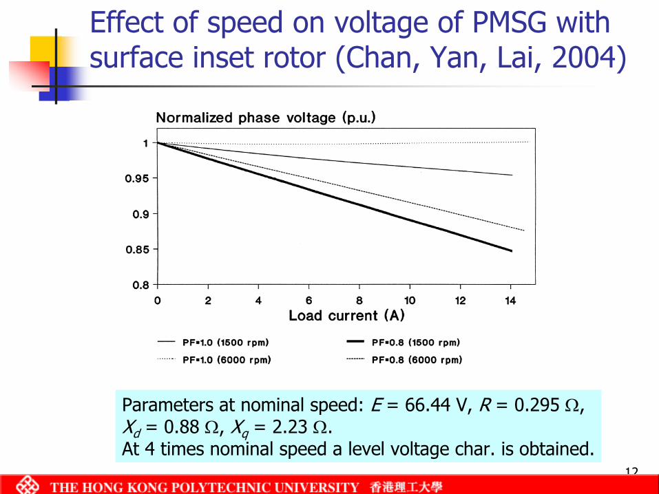
Effect of speed on voltage of PMSG with surface inset rotor (Chan, Yan, Lai, 2004)
Parameters at nominal speed: E = 66.44 V, R = 0.295 Ω, Xd = 0.88 Ω, Xq = 2.23 Ω.At 4 times nominal speed a level voltage char. is obtained.
13
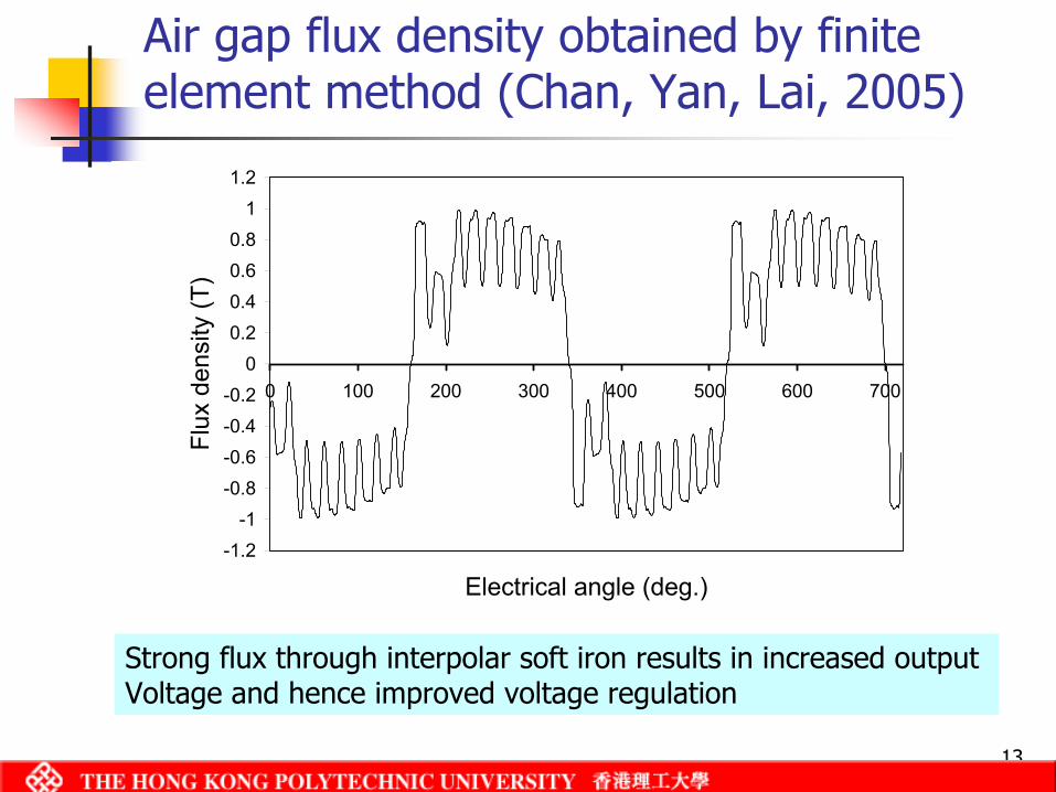
Air gap flux density obtained by finite element method (Chan, Yan, Lai, 2005)
-1.2-1
-0.8-0.6-0.4-0.2
00.20.40.60.8
11.2
0 100 200 300 400 500 600 700
Electrical angle (deg.)
Flux
den
sity
(T)
Strong flux through interpolar soft iron results in increased output Voltage and hence improved voltage regulation
14
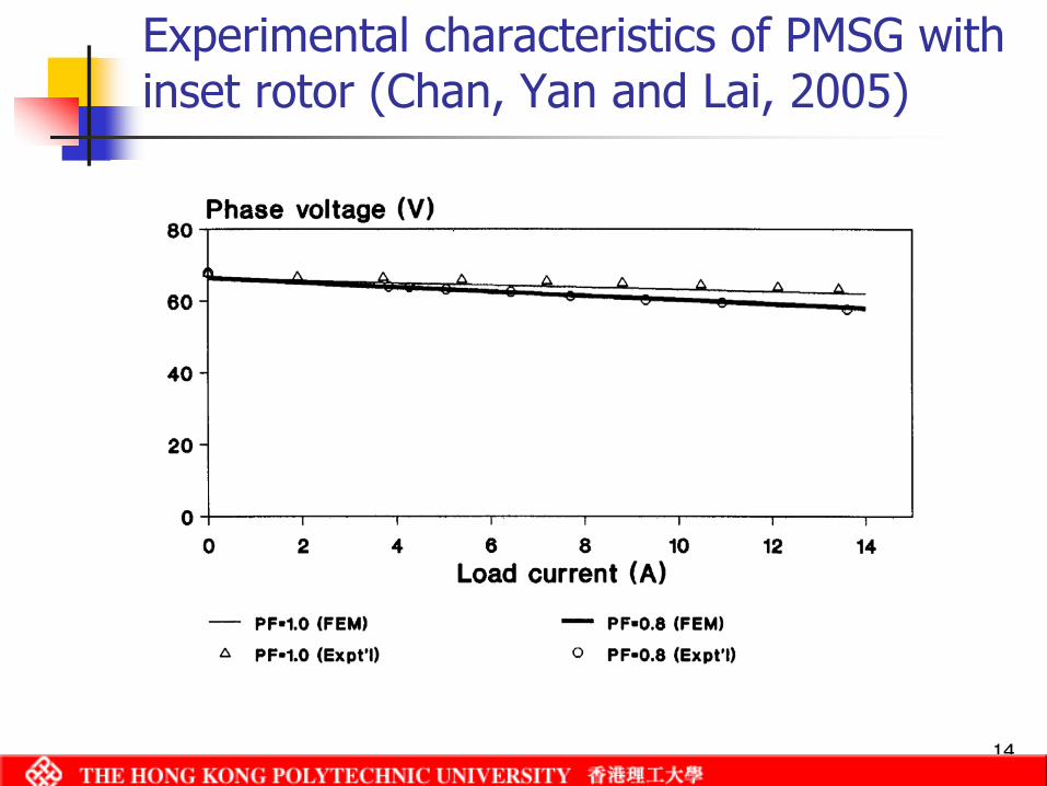
Experimental characteristics of PMSG with inset rotor (Chan, Yan and Lai, 2005)
15
High-speed PMSGs
Suitable for DG driven by micro-turbinesApplicable in regions with abundant natural gas resourceGenerator designed to run at high speedsMain technical issues (Wang, 2002):
Electromagnetic designReduction of iron / stray lossesBearings for high-speed operationCooling problem
16
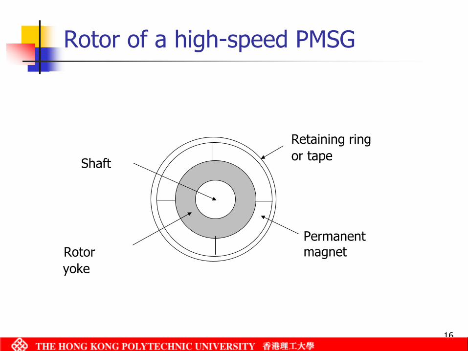
Rotor of a high-speed PMSG
Retaining ring or tape
Permanent magnetRotor
yoke
Shaft
17
Linear PM machines
Linear electric machines (LEMs) involve translational motion instead of rotational motionFor power generation, short-distance and oscillatory motions are involvedTypical application is as a wave generator that captures the energy of perpetual wave motion, e.g., the Archimedes Wave Swing (AWS) (Polinder, 2004)Different machine designs are possible, e.g. transverse flux PMSG (Polinder, 2005), tubular PMSM (Amara, 2005)
18
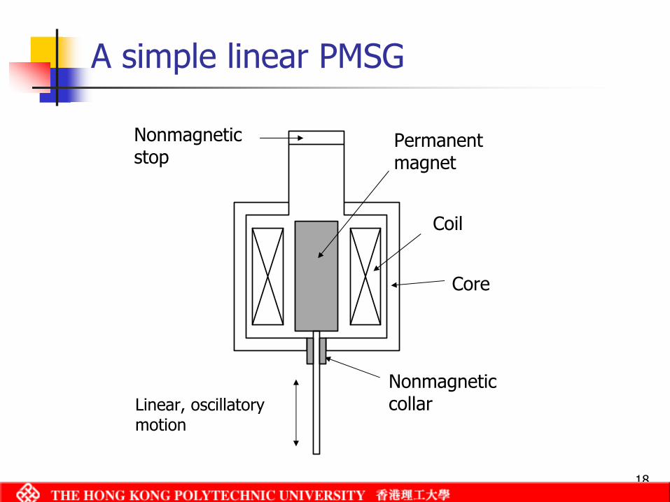
A simple linear PMSG
Permanent magnet
Coil
Nonmagneticstop
Core
Nonmagnetic collarLinear, oscillatory
motion
19
Axial-flux PMSG
Electric machine with flat annulus air gapMain flux in axial direction, active conductors in radial directionsSuitable for low-speed, direct drive wind energy systems because large number of poles can be accommodated
20
Types of axial-flux PMSG
Modular PM generator with toroidal stator winding (Muljadi, 1999)‘Torus’ generator with double-sided stator (Wu and Chalmers, 1995 and 1999)Axial PMSG with toothed stator core (Hwang, 2004; Parvianen, 2005)Axial PMSG with coreless air gap winding (Chan and Lai, 2007)
Outer rotor, single-sided designZero iron loss, cogging torqueZero magnetic pullSuitable for both vertical or horizontal axis wind turbines
21
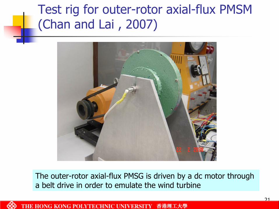
Test rig for outer-rotor axial-flux PMSM(Chan and Lai , 2007)
The outer-rotor axial-flux PMSG is driven by a dc motor through a belt drive in order to emulate the wind turbine
22
Test results
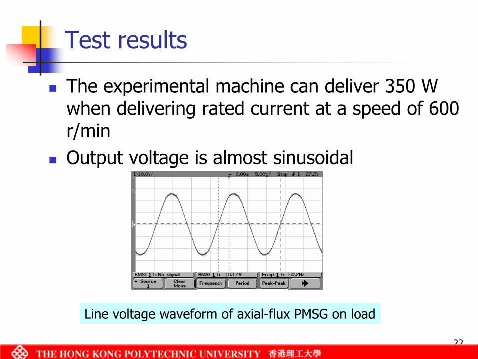
The experimental machine can deliver 350 W when delivering rated current at a speed of 600 r/minOutput voltage is almost sinusoidal
Line voltage waveform of axial-flux PMSG on load
23
Variable-speed PMSG connected to grid
Variable-speed operation needed to optimize energy capture from the windFrequency converter is required between generator and the power network Maximum power control strategy needs to be devised
Using rectifier, boost chopper and inverter (Amei, 2002)Using PWM rectifer, intermediate dc circuit and PWM inverter (Chinchilla, 2006)
24
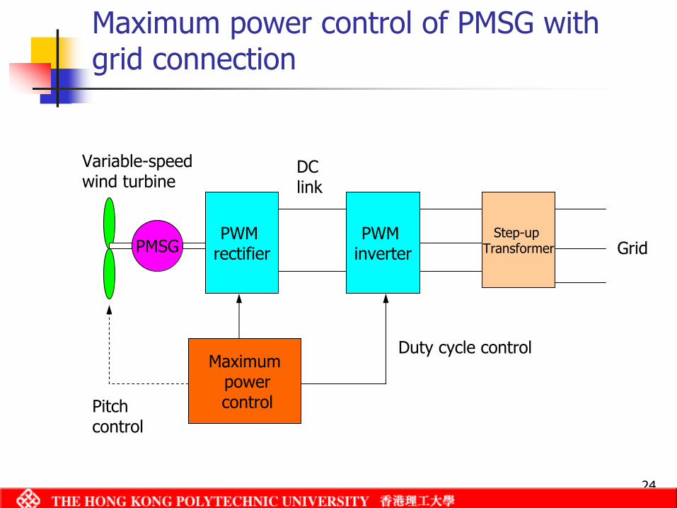
Maximum power control of PMSG with grid connection
Variable-speedwind turbine
PMSGPWM
rectifierPWM
inverterStep-up
Transformer
Maximumpowercontrol
Grid
Pitch control
Duty cycle control
DClink
25
Conclusions (1)
PMSG is suitable for distributed generationAdvantages are compactness, light weight, and high efficiencyVariable machine configurations are possible
Radial or axial flux machinesLinear machinesOuter-rotor designLight-weight design (e.g., spoke-wheel concept)Torus machinesToothless or coreless designs
26
Conclusions (2)
Future work on PMSG might include:Refined performance analysisLoss or thermal modelsDesign optimizationApplication of finite element analysisControl for grid integrationNiche application areas, such as hybrid EVs, micro-turbine generators, etc.