Embed Size (px)
Citation preview
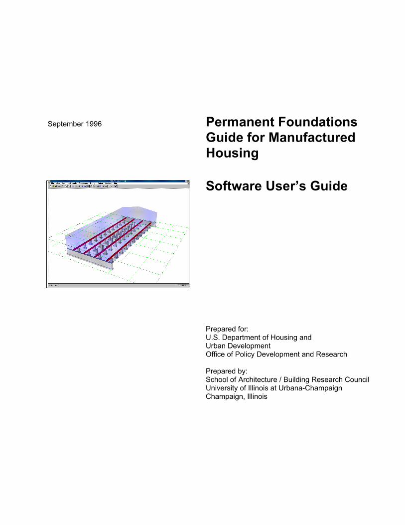
September 1996 Permanent Foundations Guide for Manufactured Housing
Software User’s Guide
Prepared for:U.S. Department of Housing andUrban DevelopmentOffice of Policy Development and Research
Prepared by:School of Architecture / Building Research CouncilUniversity of Illinois at Urbana-ChampaignChampaign, Illinois

Permanent Foundations Guide for Manufactured Housing
Software User’s Guide
Prepared for:U.S. Department of Housing andUrban DevelopmentOffice of Policy Development and Research
Prepared by:School of Architecture / Building Research CouncilUniversity of Illinois at Urbana-ChampaignChampaign, Illinois
September 1996

Notice
The U.S. Government does not endorse products or manufacturers. Trade or manufacturer’s names appear herein solely because they are considered essential to the object of this report.
The contents of this report are the views of the contractor and do not necessarily reflect the views or policies of the U.S. Department of Housing and Urban Development or the U.S. Government.

Foreword
This Computer Software and its guide are intended to automate the Permanent Foundation Guide for Manufactured Housing. The Software provides a method of verifying that a foundation type will meet support and anchorage requirements for permanent foundations that are necessary to minimize manufactured home damage during high winds or earthquakes.
The software has been prepared in a Windows environment, is graphics oriented, and requires a minimum of keyboard entry. Most data is selected from scroll boxes of typical values. The worksheets can be printed when the design is complete, and an assortment of graphics can also be printed. The guidebook explains the use of the software and illustrates the solution of the two examples presented in the handbook.
The software and guidebook will be extremely useful to all who are involved in the approval of mortgage insurance for manufactured homes on permanent foundations: engineers, manufacturers, HUD Field Office Staff, and site owners.
Michael A. Stegman Assistant Secretary for Policy
Development and Research
iii

Acknowledgments
This Software and its documentation ( called The Guidebook ) was prepared by the Building Research Council of the School of Architecture at the University of Illinois at Urbana/Champaign under contract to the Division of Program Monitoring and Research of the U.S. Department of Housing and Urban Development. Special thanks are extended to William E. Freeborne, the Government Technical Monitor for providing experience and counsel on the manufactured housing industry, for enthusiastic support of our contract proposals, for review and comments on drafts of the development of the software and the Guidebook, and for guidance and coordination for all meetings with the various housing organizations in Washington D.C.
Thanks also goes to other individuals with HUD and from other organizations for attending meetings and contributing suggestions for incorporation in both the software and the Guidebook:
Smbat Hacopian senior structural engineer of HUD’s Manufactured Housing and Construction Standards Division
Richard Mendlen senior structural engineer at HUD Ashok Goswami Housing and Building Technology, Division of NCSBCS Paul Hancher National Conference of States on Building Codes & Standards Hushang Rais National Conference of States on Building Codes & Standards Mike Mafi Housing and Building Technology, Division of NCSBCS Richard Marshall National Institute of Standards & Technology Frank Walter Manufactured Housing Institute Michael Werner Housing and Building Technology, Division of NCSBCS
iv
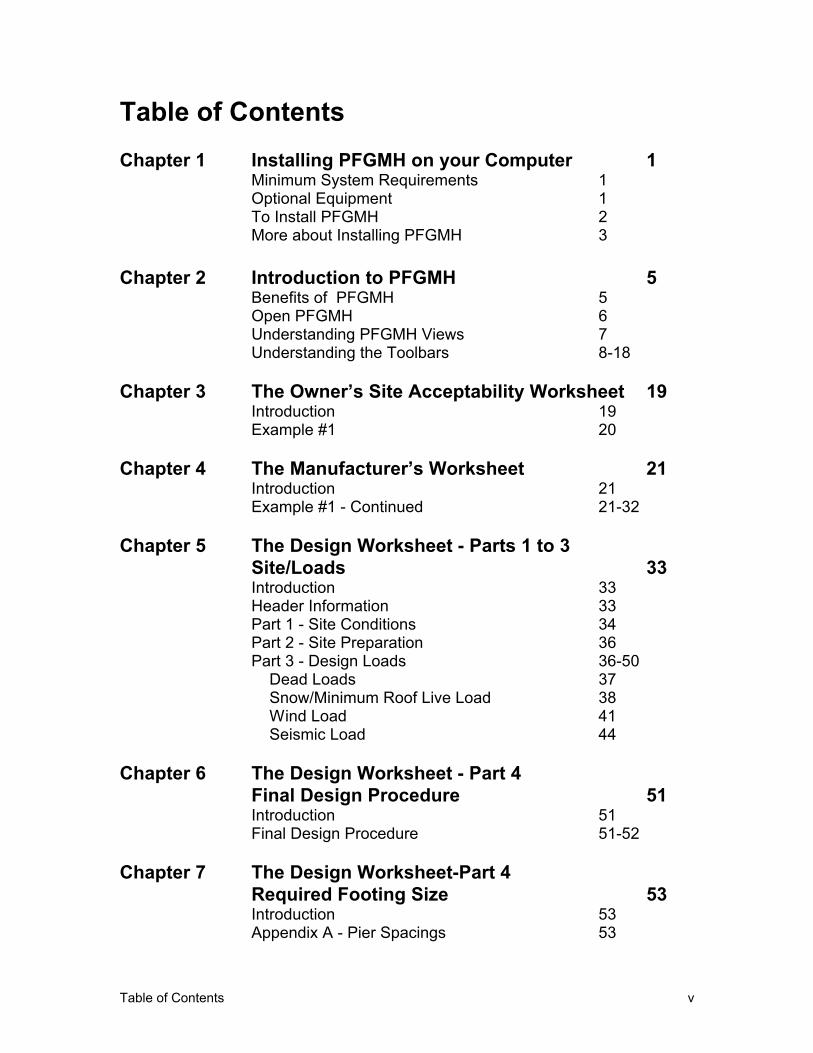
Table of Contents
Chapter 1
Chapter 2
Chapter 3
Chapter 4
Chapter 5
Chapter 6
Chapter 7
Installing PFGMH on your Computer 1 Minimum System Requirements 1 Optional Equipment 1 To Install PFGMH 2 More about Installing PFGMH 3
Introduction to PFGMH 5 Benefits of PFGMH 5 Open PFGMH 6 Understanding PFGMH Views 7 Understanding the Toolbars 8-18
The Owner’s Site Acceptability Worksheet 19 Introduction Example #1
The Manufacturer’s Worksheet IntroductionExample #1 - Continued
The Design Worksheet - Parts 1 to 3 Site/Loads IntroductionHeader InformationPart 1 - Site ConditionsPart 2 - Site PreparationPart 3 - Design Loads
Dead LoadsSnow/Minimum Roof Live LoadWind LoadSeismic Load
The Design Worksheet - Part 4 Final Design Procedure IntroductionFinal Design Procedure
The Design Worksheet-Part 4 Required Footing Size IntroductionAppendix A - Pier Spacings
19 20
21 21 21-32
33 33 33 34 36 36-50 37 38 41 44
51 51 51-52
53 53 53
Table of Contents v
Chapter 8
Chapter 9
Chapter 10
Chapter 11
Chapter 12
Chapter 13
Chapter 14
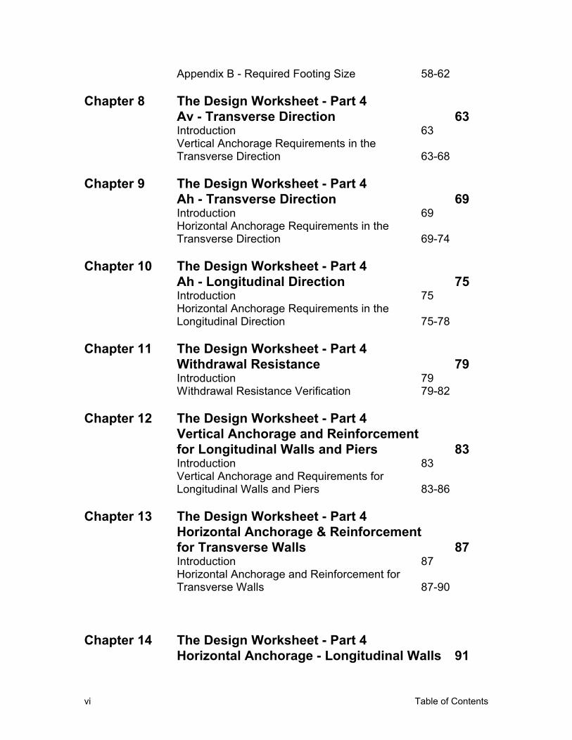
Appendix B - Required Footing Size
The Design Worksheet - Part 4Av - Transverse DirectionIntroductionVertical Anchorage Requirements in theTransverse Direction
The Design Worksheet - Part 4Ah - Transverse DirectionIntroductionHorizontal Anchorage Requirements in theTransverse Direction
The Design Worksheet - Part 4Ah - Longitudinal DirectionIntroductionHorizontal Anchorage Requirements in theLongitudinal Direction
The Design Worksheet - Part 4Withdrawal ResistanceIntroductionWithdrawal Resistance Verification
The Design Worksheet - Part 4Vertical Anchorage and Reinforcementfor Longitudinal Walls and PiersIntroductionVertical Anchorage and Requirements forLongitudinal Walls and Piers
The Design Worksheet - Part 4
58-62
63 63
63-68
69 69
69-74
75 75
75-78
79 79 79-82
83 83
83-86
Horizontal Anchorage & Reinforcementfor Transverse Walls 87Introduction 87Horizontal Anchorage and Reinforcement forTransverse Walls 87-90
The Design Worksheet - Part 4Horizontal Anchorage - Longitudinal Walls 91
vi Table of Contents
IntroductionHorizontal Anchorage for LongitudinalFoundation walls
Summary Sheet IntroductionSummary SheetBearing Area & Vertical Anchorage for Piers
91
91-94
95 95 95 96
Chapter 15
Chapter 16
Appendix A
Long Foundation Wall & Footing: Type E - GravityLoad Bearing and Withdrawal Due to Overturning 97Horizontal Anchorage in the Transverse Direction -Continuous Foundation Walls - Sliding 98Horizontal Anchorage in the Longitudinal Direction -Exterior Continuous Foundation Walls - Sliding
Proficient PFGMH Users - Example #2 IntroductionExample #2Owner’s Site Acceptability WorksheetManufacturer’s WorksheetDesign WorksheetPart 1 - Site ConditionsPart 2 - Site PreparationPart 3 - Design Loads
Snow Load/Minimum Roof Live LoadWind LoadSeismic Load
Part 4 - Final Design ProcedureRequired Footing Size - Appendix ARequired Footing Size - Appendix BVertical Anchorage Requirements in theTransverse Direction - Av - Overturning & UpliftHorizontal Anchorage Requirements in theTransverse Direction - Ah - SlidingHorizontal Anchorage Requirements in theLongitudinal Direction - Ah - Sliding
99-100
101 101 101 102 102-107 108 108-110 110 111 111-113 113-115 115-117 117 118 119
120
121-125
125-128 Withdrawal Resistance Verification - Appendix C 128-129Vertical Anchorage and reinforcement forLongitudinal Foundation Walls and Piers 129Horizontal Anchorage and Reinforcement forTransverse Foundation Walls 130Horizontal Anchorage for LongitudinalFoundation Walls 131Summary Sheet 131-132
Example #1 - Foundation Concept Type E1
Table of Contents vii
Multi-Section Unit - Output 133 Sample Graphics 133-134Owner’s Site Acceptability Worksheet E-1 to E-2Manufacturer’s Worksheet E-3 to E-5Design Worksheet F-1 to F-22
Appendix B Example #2 - Foundation Concept Type C1Single-Section Unit - Output 135Sample Graphics 135-136Owner’s Site Acceptability Worksheet E-1 to E-2Manufacturer’s Worksheet E-3 to E-5Design Worksheet F-1 to F-22
viii Table of Contents
Chapter 1 Installing PFGMH on Your Computer 1
Chapter 1 Installing PFGMH on Your Computer
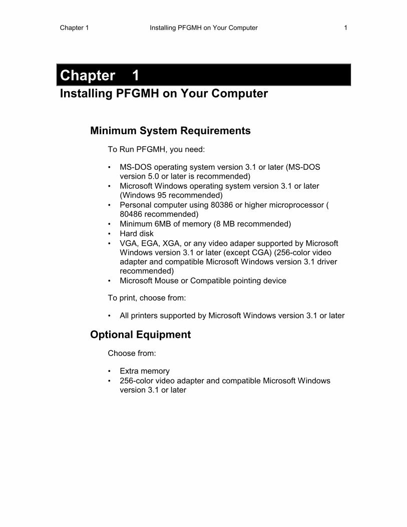
Minimum System Requirements
To Run PFGMH, you need:
• MS-DOS operating system version 3.1 or later (MS-DOS version 5.0 or later is recommended)
• Microsoft Windows operating system version 3.1 or later (Windows 95 recommended)
• Personal computer using 80386 or higher microprocessor ( 80486 recommended)
• Minimum 6MB of memory (8 MB recommended) • Hard disk • VGA, EGA, XGA, or any video adaper supported by Microsoft
Windows version 3.1 or later (except CGA) (256-color video adapter and compatible Microsoft Windows version 3.1 driver recommended)
• Microsoft Mouse or Compatible pointing device
To print, choose from:
• All printers supported by Microsoft Windows version 3.1 or later
Optional Equipment
Choose from:
• Extra memory • 256-color video adapter and compatible Microsoft Windows
version 3.1 or later

2 Installing PFGMH on Your Computer Chapter 1
To Install PFGMH
For Windows 3.1:
1. Make sure that your computer and your monitor are turned on and that you have installed Microsoft Windows.
2. If Windows isn’t already running, start Windows by typing WIN at the C> prompt.
If the Windows Program Manager isn’t open, double-click the Program Manager icon.
-Or-
If Windows is already running, close all applications and go to the Program Manager.
3. Install Win32s Library: a. Insert the disk numbered disk 1 that references
“setup” into drive A or drive B and close the drive door, if necessary.
b. Choose Run from the Program Manager File menu. c. Type A: setup or B: setup (depending on the drive
you’re using) in the command line box and click OK. d. Follow the instructions on the screen. e. Re-start Windows.
4. Insert PFGMH disk 1 into drive A or drive B and close the door, if necessary.
5. Choose Run from the Program Manager File menu. 6. Type A: setup or B: setup (depending on the drive you’re
using) in the command line box and click OK. 7. Follow the instructions on the screen.
For Windows 95:
1. Make sure that your computer and your monitor are turned on and that you have installed Microsoft Windows.
2. Insert PFGMH disk 1 into drive A or drive B and close the door, if necessary.
3. Choose Run from the Start menu. 4. Type A: setup or B: setup (depending on the drive you’re
using) in the command line box and click OK. 5. Follow the instructions on the screen.
More About Installing PFGMH

Chapter 1 Installing PFGMH on Your Computer 3
• PFGMH requires a Mouse-- If you don’t know how to use a mouse, or to choose from Windows Menus, review your Window’s User’s Manual.
• Make Back-up copies of your PFGMH diskettes--store the originals in a safe place.

4 Installing PFGMH on Your Computer Chapter 1
Chapter 2 Introduction to PFGMH 5
Chapter 2 Introduction to PFGMH
Benefits of PFGMH
Whether you are an owner, a developer, or an architect/engineer working for an owner, PFGMH will provide a powerful assistance in the preparation of the Worksheets necessary for application of an FHA mortgage. PFGMH will rapidly determine the gravity and lateral loads to apply to the preferred Manufactured Housing Unit, and quickly assess the permanent foundation requirements for connection to the unit superstructure. PFGMH allows the user to perform all the tasks contained in the Permanent Foundation Guide for Manufactured Housing, HUD Handbook 4930.3-REV-2; hereafter referred to as the “Handbook”.
PFGMH is arranged to mirror the procedures of the “Handbook” and eliminate use of the Appendix B charts, which of necessity were formulated on many simplifying assumptions and are therefore conservative. The results from PFGMH will be exact, based on the user’s input values into the program and will be in accordance with the requirements of ASCE 7-93 - Minimum Design Loads for Buildings and Other Structures. The main features of the program include: • Uses exact dimensions and loads based on ASCE 7-93,
including wind and seismic forces to compute required reactions to be resisted by the permanent foundation.
• Determines footing sizes for various foundation Types and allowable soil bearing pressures.
• Determines anchorage requirements between foundation and superstructure to resist overturning in the transverse direction and sliding in both the transverse and longitudinal directions.
• The Owner’s Site Acceptability Worksheet, Manufacturer’s Worksheet and the Design Worksheet can be easily filled out on the screen and printed with many of the values automatically entered.
• Draws the various graphical views of the foundation system selected in 2-D plan view , transverse and longitudinal section views, plus a 3D perspective.
6 Introduction of PFGMH Chapter 2
• Displays the superstructure with graphical views of dead, live or snow, wind and seismic loads as selected by the user.
• Provides an on-line version of the Handbook with hypertext links for easy navigation.
• Provides an easy to use Windows interface with on-line Help. • Provides the maps on-screen necessary to make decisions
related to geographic location. • Provides graphical display of each foundation type and its
typical details as drawn in Appendix A of the “Handbook”. • Provides on-line graphical tables of capacities to aid selection of
components and fasteners for details to resist overturning and sliding based on the foundation type selected.
Open PFGMH
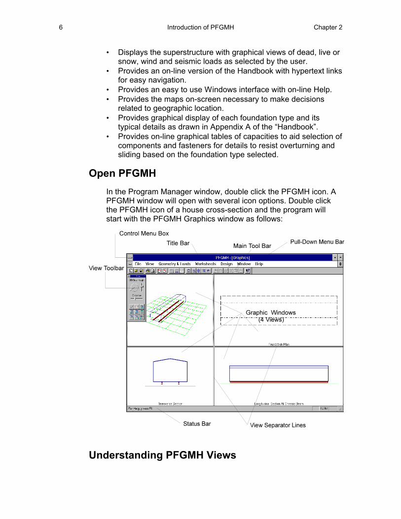
In the Program Manager window, double click the PFGMH icon. A PFGMH window will open with several icon options. Double click the PFGMH icon of a house cross-section and the program will start with the PFGMH Graphics window as follows:
Understanding PFGMH Views
Chapter 2 Introduction to PFGMH 7
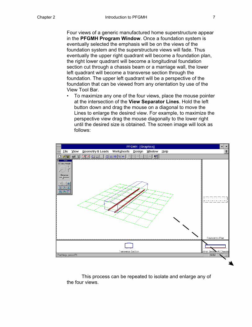
Four views of a generic manufactured home superstructure appear in the PFGMH Program Window. Once a foundation system is eventually selected the emphasis will be on the views of the foundation system and the superstructure views will fade. Thus eventually the upper right quadrant will become a foundation plan, the right lower quadrant will become a longitudinal foundation section cut through a chassis beam or a marriage wall, the lower left quadrant will become a transverse section through the foundation. The upper left quadrant will be a perspective of the foundation that can be viewed from any orientation by use of the View Tool Bar. • To maximize any one of the four views, place the mouse pointer
at the intersection of the View Separator Lines. Hold the left button down and drag the mouse on a diagonal to move the Lines to enlarge the desired view. For example, to maximize the perspective view drag the mouse diagonally to the lower right until the desired size is obtained. The screen image will look as follows:
This process can be repeated to isolate and enlarge any of the four views.
8 Introduction of PFGMH Chapter 2
Understanding the Toolbars
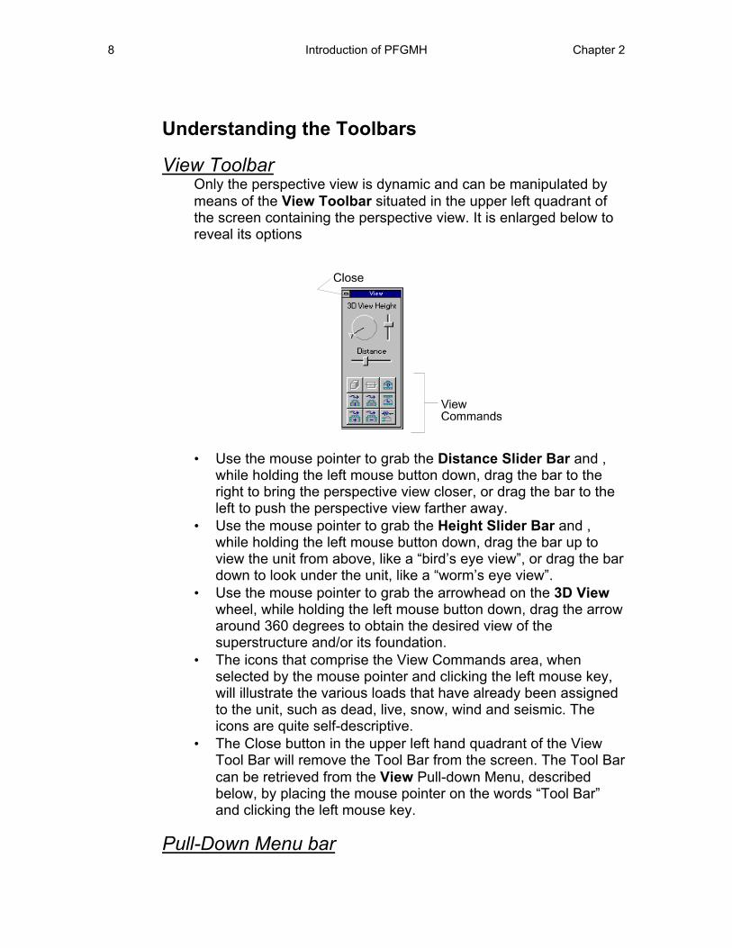
View Toolbar Only the perspective view is dynamic and can be manipulated by means of the View Toolbar situated in the upper left quadrant of the screen containing the perspective view. It is enlarged below to reveal its options
• Use the mouse pointer to grab the Distance Slider Bar and , while holding the left mouse button down, drag the bar to the right to bring the perspective view closer, or drag the bar to the left to push the perspective view farther away.
• Use the mouse pointer to grab the Height Slider Bar and , while holding the left mouse button down, drag the bar up to view the unit from above, like a “bird’s eye view”, or drag the bar down to look under the unit, like a “worm’s eye view”.
• Use the mouse pointer to grab the arrowhead on the 3D View wheel, while holding the left mouse button down, drag the arrow around 360 degrees to obtain the desired view of the superstructure and/or its foundation.
• The icons that comprise the View Commands area, when selected by the mouse pointer and clicking the left mouse key, will illustrate the various loads that have already been assigned to the unit, such as dead, live, snow, wind and seismic. The icons are quite self-descriptive.
• The Close button in the upper left hand quadrant of the View Tool Bar will remove the Tool Bar from the screen. The Tool Bar can be retrieved from the View Pull-down Menu, described below, by placing the mouse pointer on the words “Tool Bar” and clicking the left mouse key.
Pull-Down Menu bar
Chapter 2 Introduction to PFGMH 9
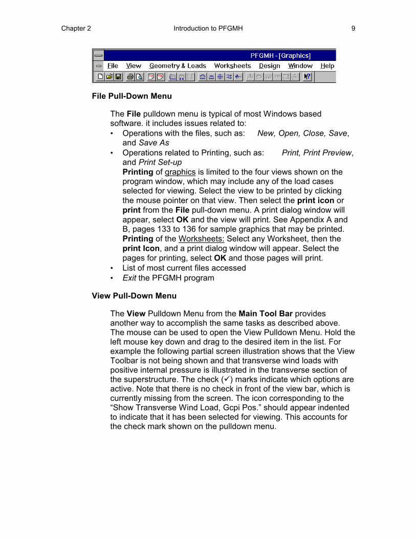
File Pull-Down Menu
The File pulldown menu is typical of most Windows based software. it includes issues related to: • Operations with the files, such as: New, Open, Close, Save,
and Save As • Operations related to Printing, such as: Print, Print Preview,
and Print Set-up Printing of graphics is limited to the four views shown on the program window, which may include any of the load cases selected for viewing. Select the view to be printed by clicking the mouse pointer on that view. Then select the print icon or print from the File pull-down menu. A print dialog window will appear, select OK and the view will print. See Appendix A and B, pages 133 to 136 for sample graphics that may be printed. Printing of the Worksheets: Select any Worksheet, then the print Icon, and a print dialog window will appear. Select the pages for printing, select OK and those pages will print.
• List of most current files accessed • Exit the PFGMH program
View Pull-Down Menu
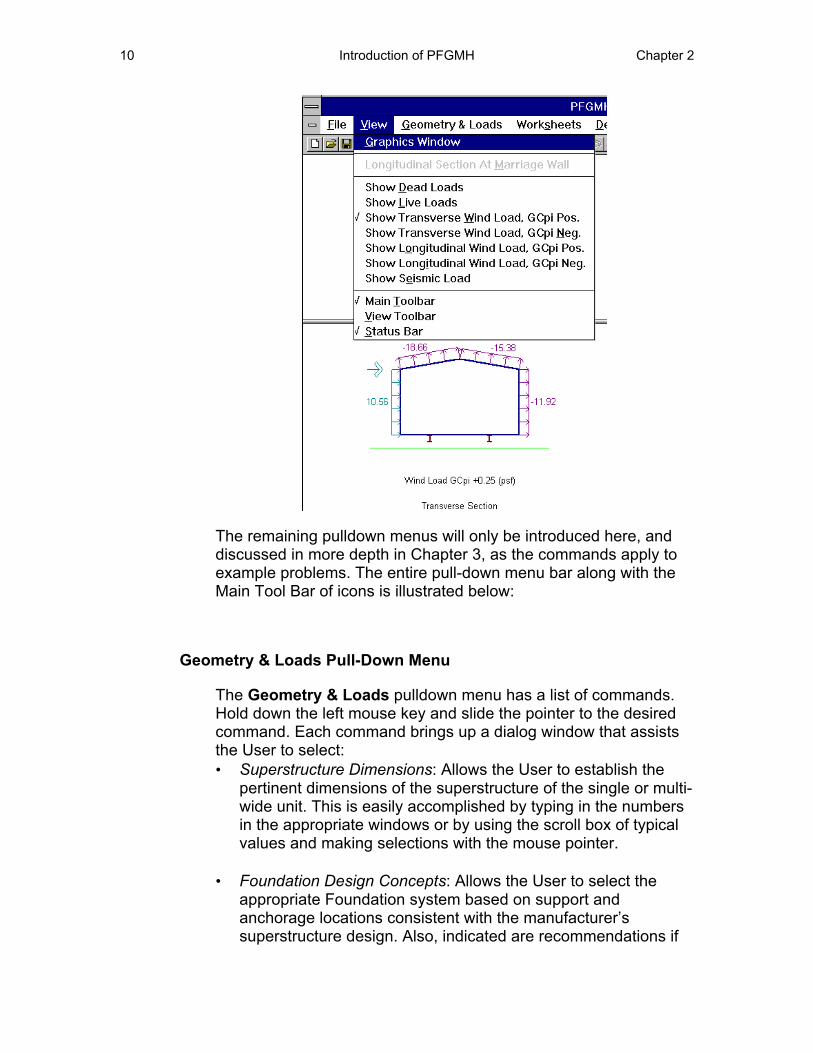
The View Pulldown Menu from the Main Tool Bar provides another way to accomplish the same tasks as described above. The mouse can be used to open the View Pulldown Menu. Hold the left mouse key down and drag to the desired item in the list. For example the following partial screen illustration shows that the View Toolbar is not being shown and that transverse wind loads with positive internal pressure is illustrated in the transverse section of the superstructure. The check (�) marks indicate which options are active. Note that there is no check in front of the view bar, which is currently missing from the screen. The icon corresponding to the “Show Transverse Wind Load, Gcpi Pos.” should appear indented to indicate that it has been selected for viewing. This accounts for the check mark shown on the pulldown menu.
10 Introduction of PFGMH Chapter 2
The remaining pulldown menus will only be introduced here, and discussed in more depth in Chapter 3, as the commands apply to example problems. The entire pull-down menu bar along with the Main Tool Bar of icons is illustrated below:
Geometry & Loads Pull-Down Menu
The Geometry & Loads pulldown menu has a list of commands. Hold down the left mouse key and slide the pointer to the desired command. Each command brings up a dialog window that assists the User to select: • Superstructure Dimensions: Allows the User to establish the
pertinent dimensions of the superstructure of the single or multi-wide unit. This is easily accomplished by typing in the numbers in the appropriate windows or by using the scroll box of typical values and making selections with the mouse pointer.
• Foundation Design Concepts: Allows the User to select the appropriate Foundation system based on support and anchorage locations consistent with the manufacturer’s superstructure design. Also, indicated are recommendations if
Chapter 2 Introduction to PFGMH 11
each foundation system is appropriate for high wind, high seismic, or deep frost protection requirements.
• Dead Loads: The dialog window for dead loads on the Superstructure has four Tabs to select floor, roof, exterior wall or marriage wall for the creation of each item’s dead load. Position the mouse pointer on the desired component and click the left mouse key to view that component’s window. The selection of another Tab permits switching easily to another component’s window. Down-arrow buttons reveal drop-down list boxes of pre-set material dead load values that can be selected by use of the mouse pointer and clicking the left mouse key. This is another option, which avoids typing in the desired values.
• Floor & Attic Live Loads: The typical floor live load is set at a default of 40 psf; however, it can be changed as desired by the User by holding down the left mouse key and graying over the present value and typing in the new value. The attic live load is only required if the roof slope permits space for an attic. The default is set to zero, but any value can be typed in as described for the floor live load. A reasonable choice is 10 psf when an attic is assumed.
• Roof Live Load: The dialog window indicates that snow load or a minimum roof live load based on the roof slope must be compared and the larger value used for design. The User can click the left mouse button when the mouse pointer is on the map button to review the Snow maps for the geographic location of the building site and read the isobar value for ground snow load in psf. Return to the Roof Live Load dialog box and use the mouse pointer to manipulate the scroll box to find the snow load magnitude, which will then be inserted without typing. The snow load equation includes other factors that are set as default values. These can be changed or the code provision can be selected for additional information about that factor by clicking the left mouse key when the mouse pointer is on the adjacent box. Whether the roof is slippery or the site is in Alaska is selected by clicking the left mouse button when the pointer is in the correct box. An “X” will verify your choice. The snow load equation is calculated and the magnitude is displayed. This value is compared against the minimum live load for the chosen roof slope and the larger of the two values is displayed and used for design.
12 Introduction of PFGMH Chapter 2
• Wind Load: The dialog window is similar in layout to that for snow load. The User reviews the Wind maps for the geographic location of the building site and reads the isobar value for wind speed in MPH. Return to the Wind Load dialog box and use the mouse pointer to manipulate the scroll box to find the wind load magnitude, which will then be inserted without typing. The procedure is then much the same as for snow loads. Magnitudes of wind load on all the superstructure surfaces are tabulated in the transverse and longitudinal directions.
• Seismic Load: The dialog window starts with a summary of the dead and snow loads already calculated at the top. Any of these values can be changed by the procedures described for the other dialog windows. The user must review the seismic maps to find the Aa and Av values for the county where the site is located. All the remainder of the seismic coefficients are default values, that can be changed if desired. The seismic base shear is calculated and then that force is distributed to the roof and floor planes.
Worksheets Pull-Down Menu
The Worksheets pulldown menu includes the commands to access the three worksheets required for submission to HUD for approval of FHA mortgage insurance. These Worksheets are intended to assist the User in the completion of the forms. Information that has already been inputted or calculated will automatically be inserted into the worksheets to facilitate their completion. Information from the Owner’s and Manufacturer’s Worksheets are automatically entered into the Design Worksheet; however, the data entered or changed in the Design Worksheet does not update the Owner’s or Manufacturer’s Worksheets. It’s a one way process.
Note: Always fill out the Owner’s and Manufacturer’s Worksheets first. • Owner’s Site Acceptability Worksheet: This form window is of
the scroll type with the up/down arrows along the vertical right side of the screen. The user types in his name, address, telephone, site location and legal description of the site in the same fashion as for most word processors. The remainder of the worksheet is a series of questions with yes/no choices. Click the left mouse key when the pointer is on the appropriate response. The response will highlight with a black border. References that are in green and also underlined in green refer to segments of the “Handbook” that pertain to the question being asked. If the user wants to read the text to better
Chapter 2 Introduction to PFGMH 13
understand the issue, click the left mouse key when the pointer is on that green reference and The On-Line “Handbook” will appear with the selected reference.
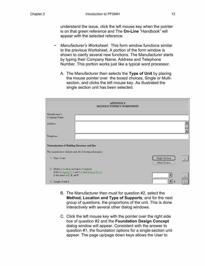
• Manufacturer’s Worksheet: This form window functions similar to the previous Worksheet. A portion of the form window is shown to clarify several new functions. The Manufacturer starts by typing their Company Name, Address and Telephone Number. This portion works just like a typical word processor.
A. The Manufacturer then selects the Type of Unit by placing the mouse pointer over the boxed choices, Single or Multi-section, and clicks the left mouse key. As illustrated the single section unit has been selected.
B. The Manufacturer then must for question #2, select the Method, Location and Type of Supports, and for the next group of questions, the proportions of the unit. This is done interactively with several other dialog windows.
C. Click the left mouse key with the pointer over the right side box of question #2 and the Foundation Design Concept dialog window will appear. Consistent with the answer to question #1, the foundation options for a single-section unit appear. The page up/page down keys allows the User to
14 Introduction of PFGMH Chapter 2
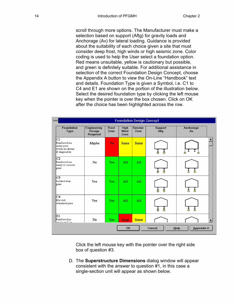
scroll through more options. The Manufacturer must make a selection based on support (Aftg) for gravity loads and Anchorage (Av) for lateral loading. Guidance is provided about the suitability of each choice given a site that must consider deep frost, high winds or high seismic zone. Color coding is used to help the User select a foundation option. Red means unsuitable, yellow is cautionary but possible, and green is definitely suitable. For additional assistance in selection of the correct Foundation Design Concept, choose the Appendix A button to view the On-Line “Handbook” text and details. Foundation Type is given a Symbol, i.e. C1 to C4 and E1 are shown on the portion of the illustration below. Select the desired foundation type by clicking the left mouse key when the pointer is over the box chosen. Click on OK after the choice has been highlighted across the row.
Click the left mouse key with the pointer over the right side box of question #3.
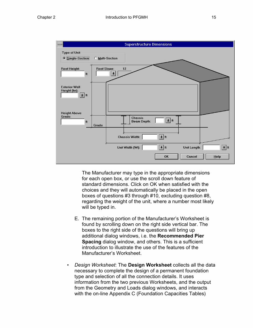
D. The Superstructure Dimensions dialog window will appear consistent with the answer to question #1, in this case a single-section unit will appear as shown below.
Chapter 2 Introduction to PFGMH 15
The Manufacturer may type in the appropriate dimensions for each open box, or use the scroll down feature of standard dimensions. Click on OK when satisfied with the choices and they will automatically be placed in the open boxes of questions #3 through #10, excluding question #8, regarding the weight of the unit, where a number most likely will be typed in.
E. The remaining portion of the Manufacturer’s Worksheet is found by scrolling down on the right side vertical bar. The boxes to the right side of the questions will bring up additional dialog windows, i.e. the Recommended Pier Spacing dialog window, and others. This is a sufficient introduction to illustrate the use of the features of the Manufacturer’s Worksheet.
• Design Worksheet: The Design Worksheet collects all the data necessary to complete the design of a permanent foundation type and selection of all the connection details. It uses information from the two previous Worksheets, and the output from the Geometry and Loads dialog windows, and interacts with the on-line Appendix C (Foundation Capacities Tables)
16 Introduction of PFGMH Chapter 2
from the “Handbook”. Thus it permits final selection of the following items:
A. Selection of spacing, depth, and size of footings based on soil bearing capacity and frost protection.
B. Selection of size, spacing and quantity of anchors to resist pullout under an overturning situation due to wind and/or seismic forces.
C. Selection of the method, size, spacing and quantity of anchors to resist sliding in the transverse direction, and
D. Selection of the method, size, spacing and quantity of anchors to resist sliding in the longitudinal direction.
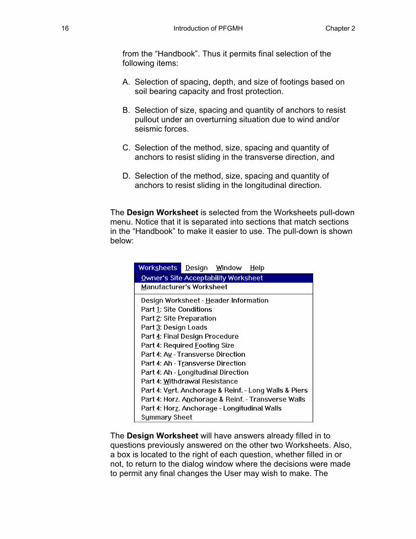
The Design Worksheet is selected from the Worksheets pull-down menu. Notice that it is separated into sections that match sections in the “Handbook” to make it easier to use. The pull-down is shown below:
The Design Worksheet will have answers already filled in to questions previously answered on the other two Worksheets. Also, a box is located to the right of each question, whether filled in or not, to return to the dialog window where the decisions were made to permit any final changes the User may wish to make. The
Chapter 2 Introduction to PFGMH 17
window layout is similar to the other Worksheets and Chapter 5 will further elaborate during the solution of an example problem.
Design
The Design pull-down menu contains the commands that contain dialog windows of information, such as load summaries, and solve the equations that provide the required forces for design. They include the following dialog windows:
• Gravity Load Footing Size • Overturning • Transverse Sliding • Longitudinal Sliding
The manipulation of the variables in these dialog windows, helps the User to arrive at realistic foundation bearing and anchorage forces, which are automatically input into the Design Worksheet.
Window
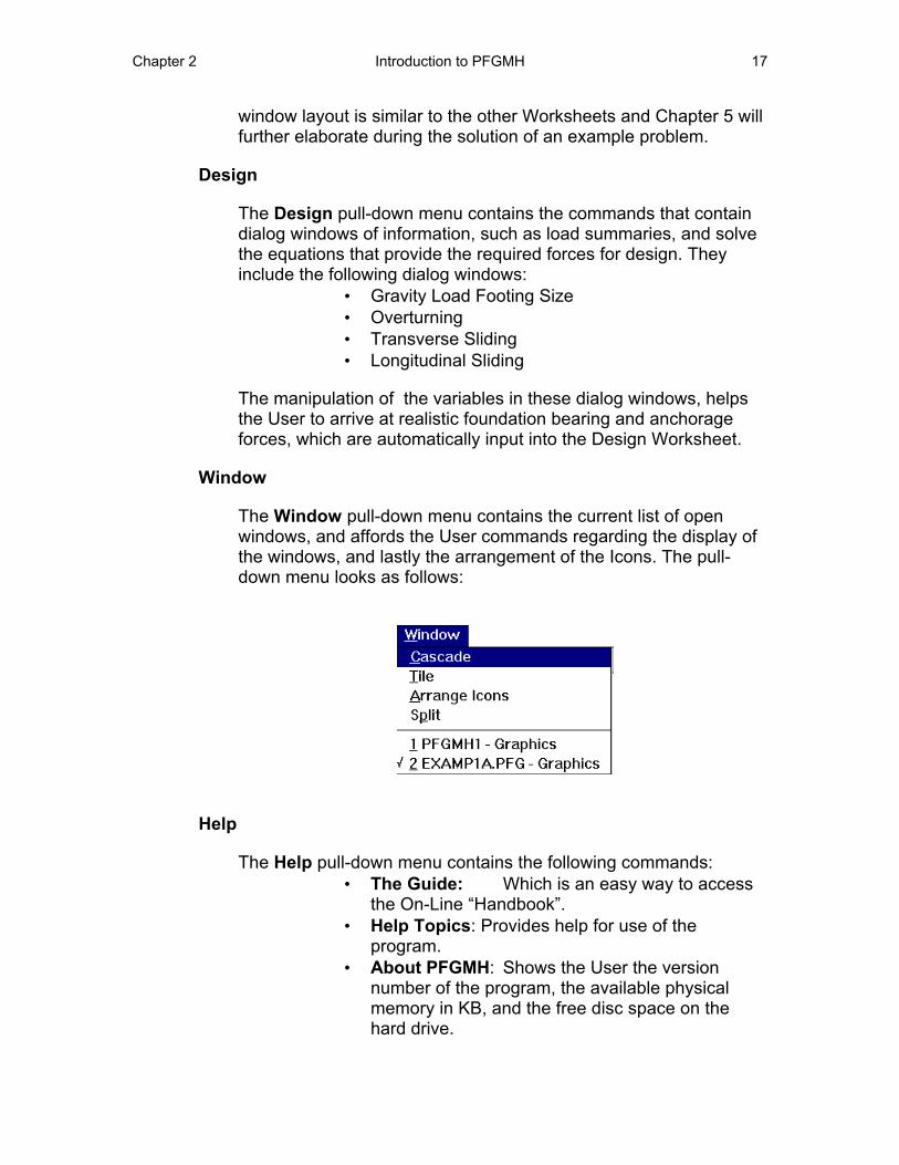
The Window pull-down menu contains the current list of open windows, and affords the User commands regarding the display of the windows, and lastly the arrangement of the Icons. The pull-down menu looks as follows:
Help
The Help pull-down menu contains the following commands: •
•
•
The Guide: Which is an easy way to accessthe On-Line “Handbook”.Help Topics: Provides help for use of theprogram.About PFGMH: Shows the User the versionnumber of the program, the available physicalmemory in KB, and the free disc space on thehard drive.
18 Introduction of PFGMH Chapter 2
Main Tool Bar
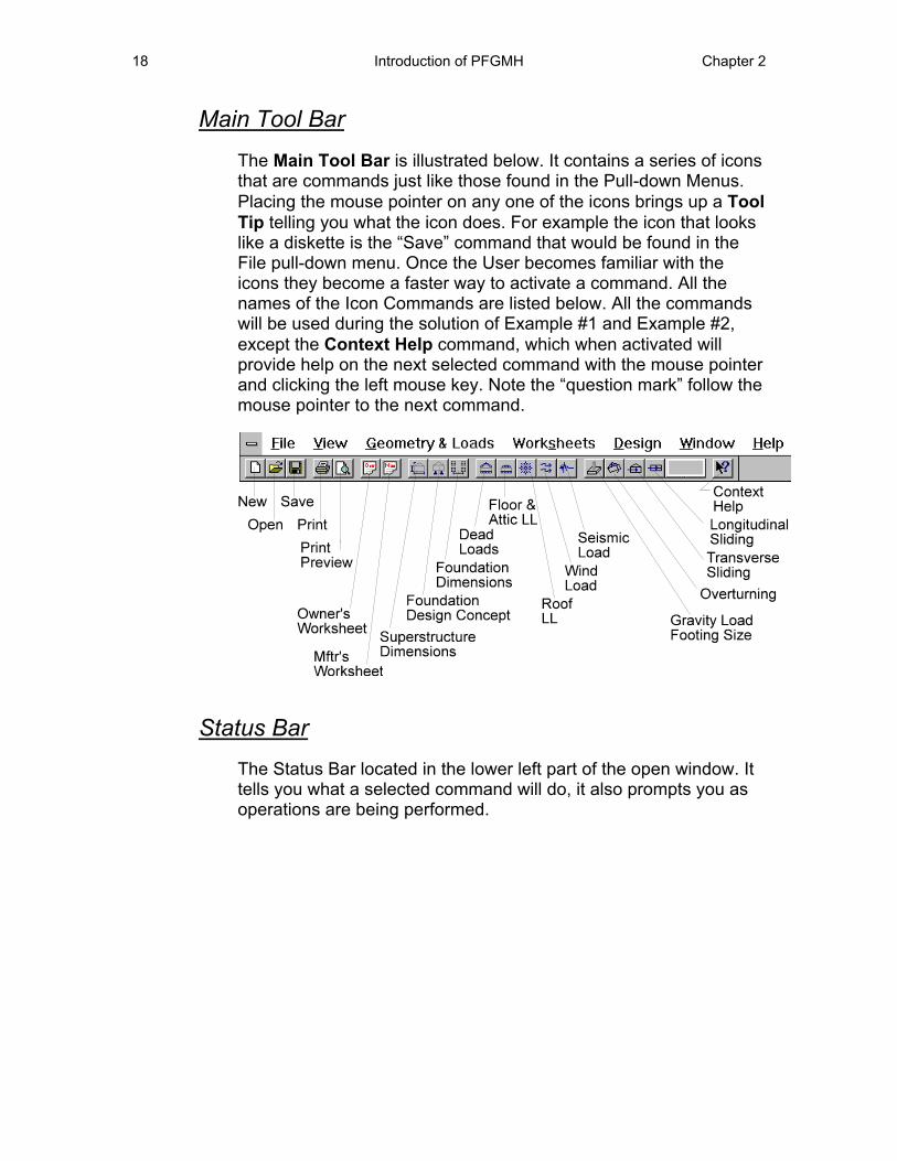
The Main Tool Bar is illustrated below. It contains a series of icons that are commands just like those found in the Pull-down Menus. Placing the mouse pointer on any one of the icons brings up a Tool Tip telling you what the icon does. For example the icon that looks like a diskette is the “Save” command that would be found in the File pull-down menu. Once the User becomes familiar with the icons they become a faster way to activate a command. All the names of the Icon Commands are listed below. All the commands will be used during the solution of Example #1 and Example #2, except the Context Help command, which when activated will provide help on the next selected command with the mouse pointer and clicking the left mouse key. Note the “question mark” follow the mouse pointer to the next command.
Status Bar
The Status Bar located in the lower left part of the open window. It tells you what a selected command will do, it also prompts you as operations are being performed.
Chapter 3 The Owner’s Site Acceptability Worksheet 19
Chapter 3 The Owner’s Site Acceptability Worksheet
Introduction
This Chapter will take the User through the process of designing a Permanent Foundation for a manufactured home that will be acceptable to the HUD Field Office to facilitate application for an FHA mortgage. It is recommended that the process always begin with the completion of the Worksheets and use of the dialog windows to assist in that process. The example #1 to be worked is taken from the “Handbook” in Appendix G. It is assumed that the Owner, with guidance from a registered engineer and possibly a geotechnical engineer (as required) will complete this Worksheet.
Example #1
Given: John Doe desires a permanent foundation for a Multi-Section Unit manufactured home composed of two nominal 14 foot units that are 56 feet long. The site is located in Champaign, IL. The Floor plan design John Doe prefers has two large openings along the marriage wall that are adjacent to each other, 16 feet and 12 feet wide, respectively. The remainder of the marriage wall is continuous.
Solution: The following sequence is recommended: A. Select the Owner’s Site Acceptability Worksheet from the
icon or the Worksheet pull-down menu. The Form Window will appear on the screen.
B. Type in the appropriate Owner information. C. Proceed through the questions and appropriately place the
mouse pointer over the desired response. Click the left mouse key and a dark box outline will log your answer.
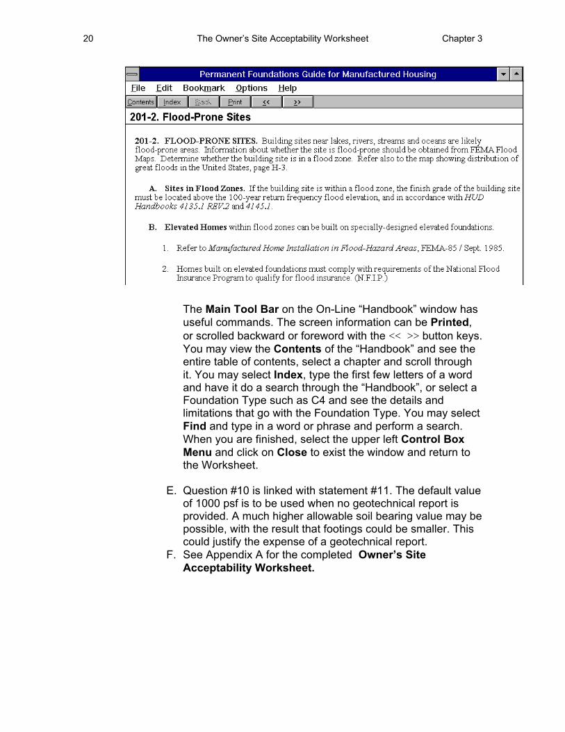
D. Select the green (typed and underlined) references from the “Handbook” for assistance. For example, if question #2 on “flood prone sites” needs clarification, place the mouse pointer on the reference (201-2) and click the left mouse key. The On-Line “Handbook” will appear with the text from that section of the “Handbook” as follows:
20 The Owner’s Site Acceptability Worksheet Chapter 3
The Main Tool Bar on the On-Line “Handbook” window has useful commands. The screen information can be Printed, or scrolled backward or foreword with the << >> button keys. You may view the Contents of the “Handbook” and see the entire table of contents, select a chapter and scroll through it. You may select Index, type the first few letters of a word and have it do a search through the “Handbook”, or select a Foundation Type such as C4 and see the details and limitations that go with the Foundation Type. You may select Find and type in a word or phrase and perform a search. When you are finished, select the upper left Control Box Menu and click on Close to exist the window and return to the Worksheet.
E. Question #10 is linked with statement #11. The default value of 1000 psf is to be used when no geotechnical report is provided. A much higher allowable soil bearing value may be possible, with the result that footings could be smaller. This could justify the expense of a geotechnical report.
F. See Appendix A for the completed Owner’s Site Acceptability Worksheet.
Chapter 4 The Manufacturer’s Worksheet 21
Chapter 4 The Manufacturer’s Worksheet
Introduction
The Manufacturer is expected to complete this Worksheet for the Owner. It is assumed that they have met and discussed the various superstructure options, floor plan layouts and the site. The following information will assist the Manufacturer to complete the Worksheet. Example #1 from the “Handbook” is continued. It is assumed that whoever fills out this Worksheet is a “User” of the program. Thus, in this case the “User” is the Manufacturer.
Example #1 - Continued
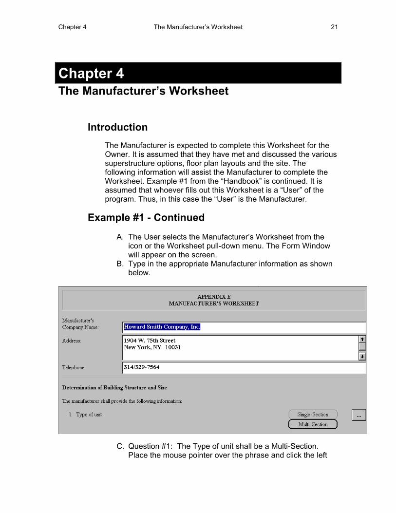
A. The User selects the Manufacturer’s Worksheet from the icon or the Worksheet pull-down menu. The Form Window will appear on the screen.
B. Type in the appropriate Manufacturer information as shown below.
C. Question #1: The Type of unit shall be a Multi-Section. Place the mouse pointer over the phrase and click the left
22 Manufacturer’s Worksheet Chapter 4
mouse key. A black border will appear indicating the selection.
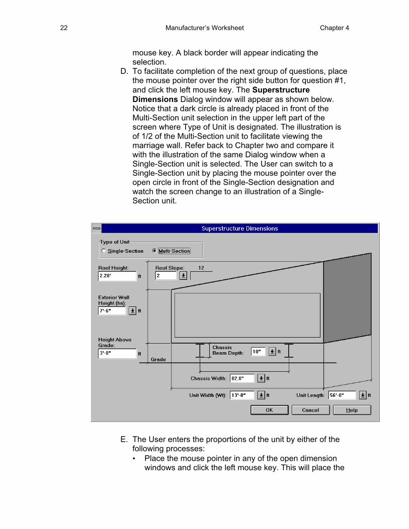
D. To facilitate completion of the next group of questions, place the mouse pointer over the right side button for question #1, and click the left mouse key. The Superstructure Dimensions Dialog window will appear as shown below. Notice that a dark circle is already placed in front of the Multi-Section unit selection in the upper left part of the screen where Type of Unit is designated. The illustration is of 1/2 of the Multi-Section unit to facilitate viewing the marriage wall. Refer back to Chapter two and compare it with the illustration of the same Dialog window when a Single-Section unit is selected. The User can switch to a Single-Section unit by placing the mouse pointer over the open circle in front of the Single-Section designation and watch the screen change to an illustration of a Single-Section unit.
E. The User enters the proportions of the unit by either of the following processes: • Place the mouse pointer in any of the open dimension
windows and click the left mouse key. This will place the
Chapter 4 The Manufacturer’s Worksheet 23
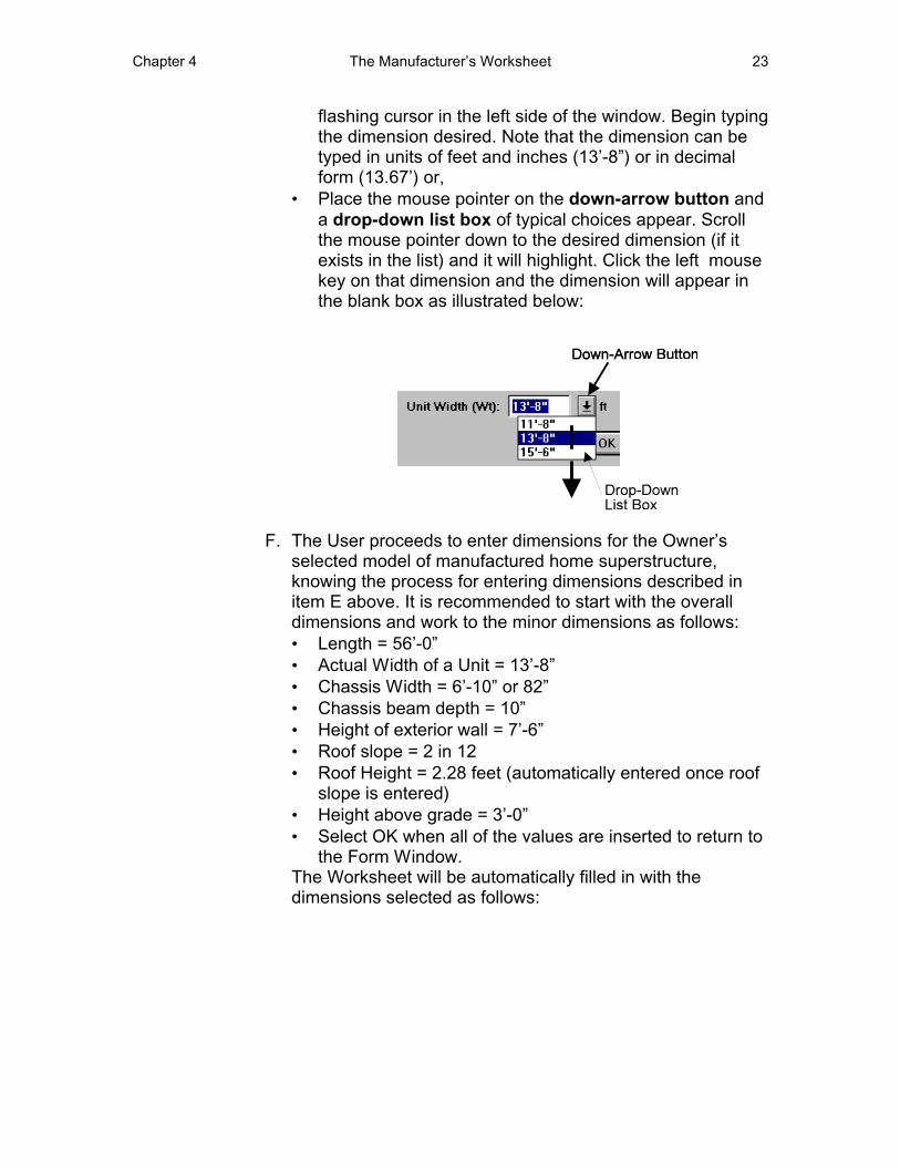
flashing cursor in the left side of the window. Begin typing the dimension desired. Note that the dimension can be typed in units of feet and inches (13’-8”) or in decimal form (13.67’) or,
• Place the mouse pointer on the down-arrow button and a drop-down list box of typical choices appear. Scroll the mouse pointer down to the desired dimension (if it exists in the list) and it will highlight. Click the left mouse key on that dimension and the dimension will appear in the blank box as illustrated below:
F. The User proceeds to enter dimensions for the Owner’s selected model of manufactured home superstructure, knowing the process for entering dimensions described in item E above. It is recommended to start with the overall dimensions and work to the minor dimensions as follows: • Length = 56’-0” • Actual Width of a Unit = 13’-8” • Chassis Width = 6’-10” or 82” • Chassis beam depth = 10” • Height of exterior wall = 7’-6” • Roof slope = 2 in 12 • Roof Height = 2.28 feet (automatically entered once roof
slope is entered) • Height above grade = 3’-0” • Select OK when all of the values are inserted to return to
the Form Window. The Worksheet will be automatically filled in with the dimensions selected as follows:
24 Manufacturer’s Worksheet Chapter 4
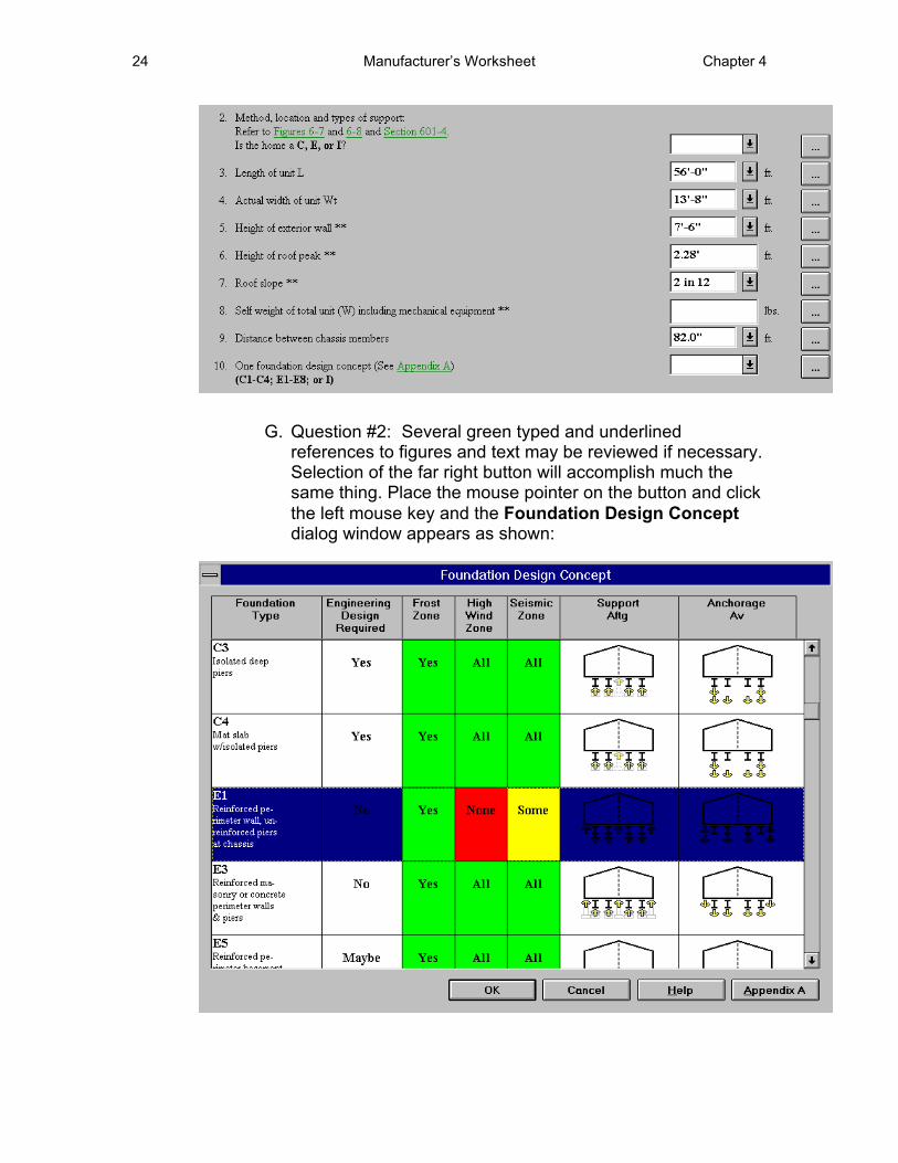
G. Question #2: Several green typed and underlined references to figures and text may be reviewed if necessary. Selection of the far right button will accomplish much the same thing. Place the mouse pointer on the button and click the left mouse key and the Foundation Design Concept dialog window appears as shown:
Chapter 4 The Manufacturer’s Worksheet 25
Note: The Multi-Section Unit Table appears, rather than the Single-Section Unit Table because of the User’s answer to question #1.
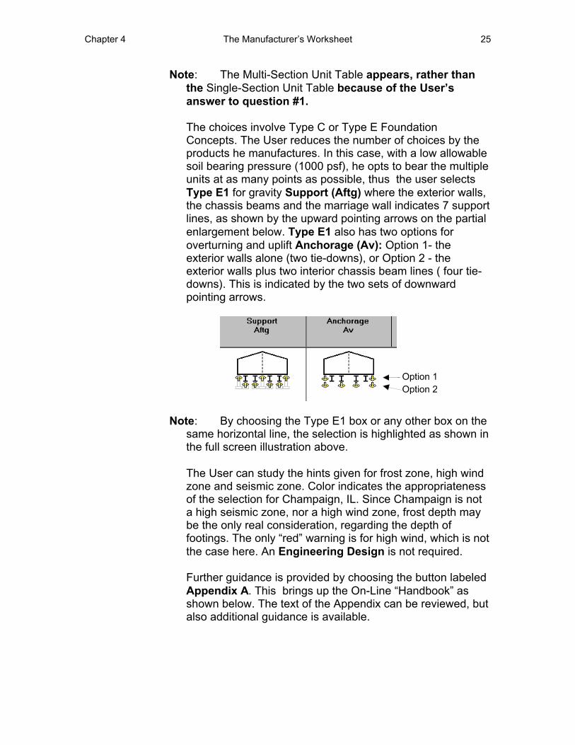
The choices involve Type C or Type E Foundation Concepts. The User reduces the number of choices by the products he manufactures. In this case, with a low allowable soil bearing pressure (1000 psf), he opts to bear the multiple units at as many points as possible, thus the user selects Type E1 for gravity Support (Aftg) where the exterior walls, the chassis beams and the marriage wall indicates 7 support lines, as shown by the upward pointing arrows on the partial enlargement below. Type E1 also has two options for overturning and uplift Anchorage (Av): Option 1- the exterior walls alone (two tie-downs), or Option 2 - the exterior walls plus two interior chassis beam lines ( four tie-downs). This is indicated by the two sets of downward pointing arrows.
Note: By choosing the Type E1 box or any other box on the same horizontal line, the selection is highlighted as shown in the full screen illustration above.
The User can study the hints given for frost zone, high wind zone and seismic zone. Color indicates the appropriateness of the selection for Champaign, IL. Since Champaign is not a high seismic zone, nor a high wind zone, frost depth may be the only real consideration, regarding the depth of footings. The only “red” warning is for high wind, which is not the case here. An Engineering Design is not required.
Further guidance is provided by choosing the button labeled Appendix A. This brings up the On-Line “Handbook” as shown below. The text of the Appendix can be reviewed, but also additional guidance is available.
26 Manufacturer’s Worksheet Chapter 4
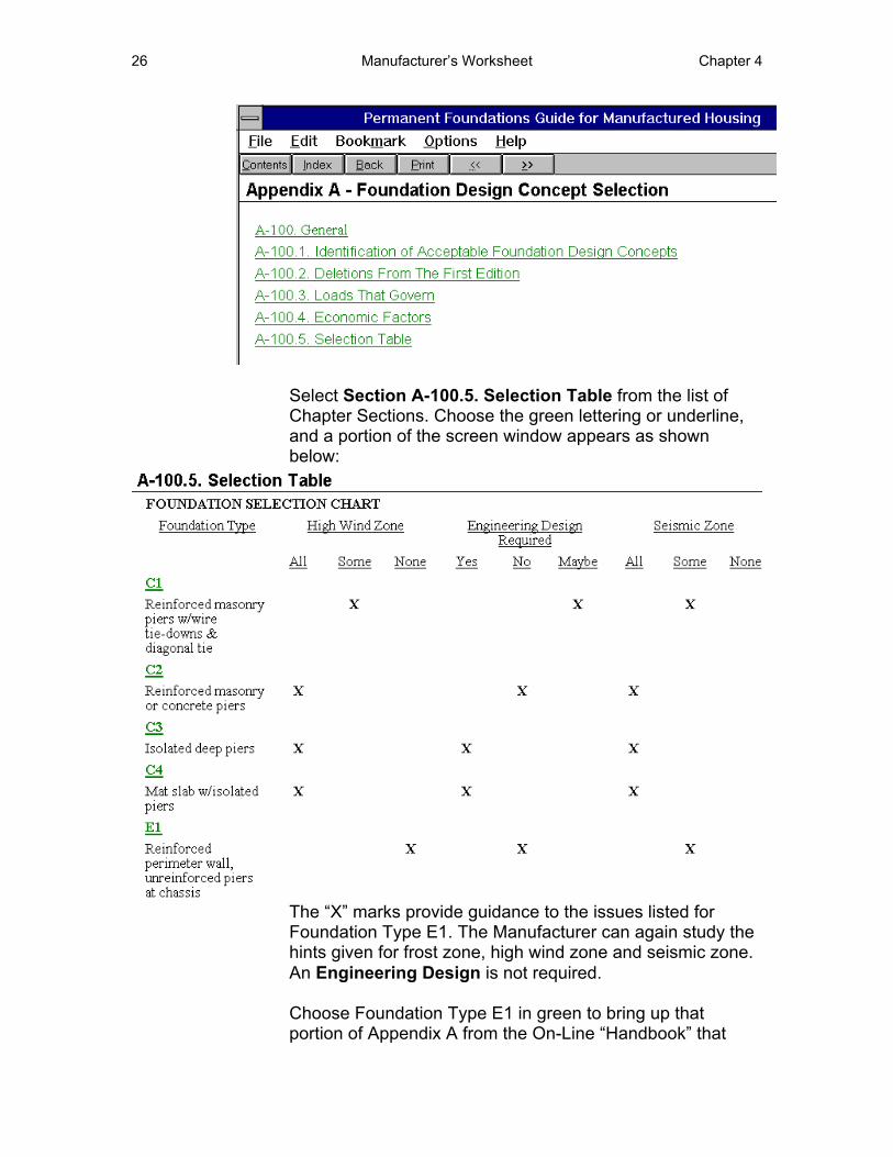
Select Section A-100.5. Selection Table from the list of Chapter Sections. Choose the green lettering or underline, and a portion of the screen window appears as shown below:
The “X” marks provide guidance to the issues listed for Foundation Type E1. The Manufacturer can again study the hints given for frost zone, high wind zone and seismic zone. An Engineering Design is not required.
Choose Foundation Type E1 in green to bring up that portion of Appendix A from the On-Line “Handbook” that
Chapter 4 The Manufacturer’s Worksheet 27
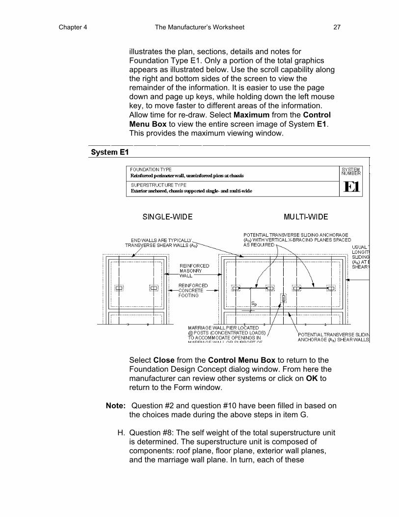
illustrates the plan, sections, details and notes for Foundation Type E1. Only a portion of the total graphics appears as illustrated below. Use the scroll capability along the right and bottom sides of the screen to view the remainder of the information. It is easier to use the page down and page up keys, while holding down the left mouse key, to move faster to different areas of the information. Allow time for re-draw. Select Maximum from the Control Menu Box to view the entire screen image of System E1. This provides the maximum viewing window.
Select Close from the Control Menu Box to return to the Foundation Design Concept dialog window. From here the manufacturer can review other systems or click on OK to return to the Form window.
Note: Question #2 and question #10 have been filled in based on the choices made during the above steps in item G.
H. Question #8: The self weight of the total superstructure unit is determined. The superstructure unit is composed of components: roof plane, floor plane, exterior wall planes, and the marriage wall plane. In turn, each of these
28 Manufacturer’s Worksheet Chapter 4
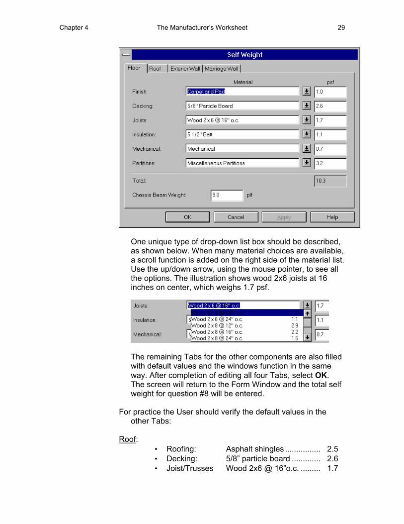
components is composed of an assemblage of structural items and finish materials. Select the right side button to bring up the Self Weight dialog window. The window is composed of four tabs, corresponding to the four basic superstructure components. The User can switch back-and-forth between the tabs by placing the mouse pointer on one of the tabs, and clicking the left mouse key. The illustration below is of the floor plane with a list of the parts that compose the floor plane. All the boxes are filled with default values. This is purposely intended to provide average values for the user unfamiliar with materials and their weights. To edit a default item or weight, the User proceeds in either of the following ways: • Select the down-arrow button as described before and a
prepared list of typical material choices will appear in the drop-down list box. Drag the mouse pointer with the left button held down until the desired selection is reached. Each item is highlighted as you scroll over it. The desired item will replace the default item in the material box and its weight will replace the default value in the load (psf) box, or
• Drag the mouse pointer over the default words to be changed. They will be highlighted. Type in the new phrase. The same process is done to change a default load magnitude.
Note: Each revision of a load magnitude, updates the total load of the component.
• The chassis beam weight is a load in pounds per lineal foot of beam length(plf). A default load of 9 plf is shown, but this can be edited as described above.
Chapter 4 The Manufacturer’s Worksheet 29
One unique type of drop-down list box should be described, as shown below. When many material choices are available, a scroll function is added on the right side of the material list. Use the up/down arrow, using the mouse pointer, to see all the options. The illustration shows wood 2x6 joists at 16 inches on center, which weighs 1.7 psf.
The remaining Tabs for the other components are also filled with default values and the windows function in the same way. After completion of editing all four Tabs, select OK. The screen will return to the Form Window and the total self weight for question #8 will be entered.
For practice the User should verify the default values in the other Tabs:
Roof: • Roofing: Asphalt shingles ................ 2.5 • Decking: 5/8” particle board ............. 2.6 • Joist/Trusses Wood 2x6 @ 16”o.c. ......... 1.7
30 Manufacturer’s Worksheet Chapter 4
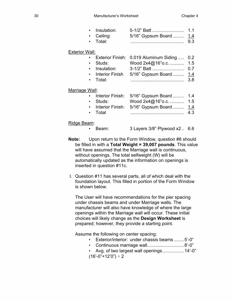
• Insulation: • Ceiling: • Total:
Exterior Wall: • Exterior Finish: • Studs: • Insulation: • Interior Finish • Total:
Marriage Wall: • Interior Finish: • Studs: • Interior Finish: • Total
Ridge Beam: • Beam:
5-1/2” Batt ......................... 1.1 5/16” Gypsum Board ......... 1.4 .......................................... 9.3
0.019 Aluminum Siding ..... 0.2 Wood 2x4@16”o.c. ........... 1.5 3-1/2” Batt ......................... 0.7 5/16” Gypsum Board ......... 1.4 .......................................... 3.8
5/16” Gypsum Board ......... 1.4 Wood 2x4@16”o.c. ........... 1.5 5/16” Gypsum Board ......... 1.4 .......................................... 4.3
3 Layers 3/8” Plywood x2 .. 6.6
Note: Upon return to the Form Window, question #8 should be filled in with a Total Weight = 39,007 pounds. This value will have assumed that the Marriage wall is continuous, without openings. The total selfweight (W) will be automatically updated as the information on openings is inserted in question #11c.
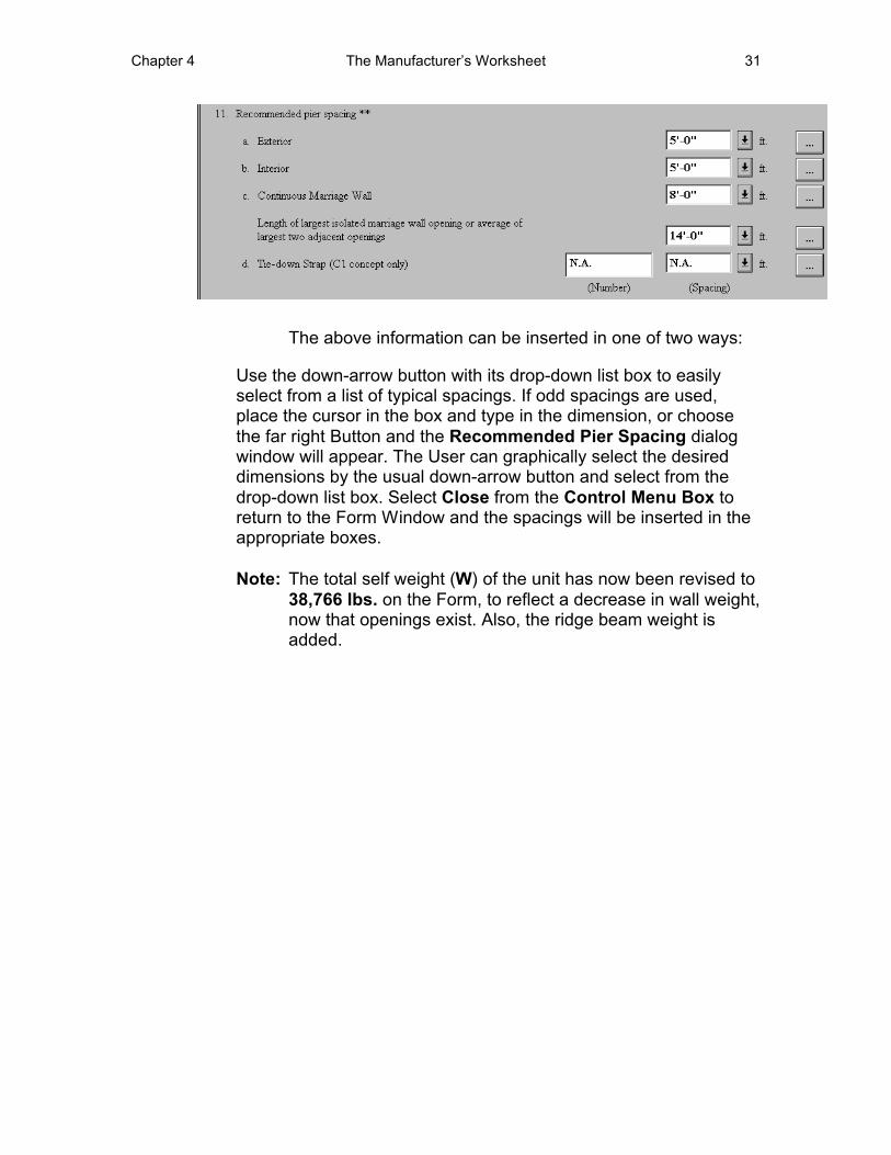
I. Question #11 has several parts, all of which deal with the foundation layout. This filled in portion of the Form Window is shown below.
The User will have recommendations for the pier spacing under chassis beams and under Marriage walls. The manufacturer will also have knowledge of where the large openings within the Marriage wall will occur. These initial choices will likely change as the Design Worksheet is prepared; however, they provide a starting point.
Assume the following on center spacing: • Exterior/interior: under chassis beams ........5’-0” • Continuous marriage wall.............................8’-0” • Avg. of two largest wall openings.................14’-0” (16’-0”+12’0”) ‚ 2
Chapter 4 The Manufacturer’s Worksheet 31
The above information can be inserted in one of two ways:
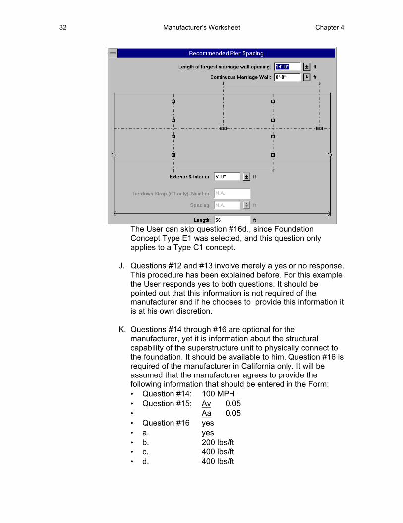
Use the down-arrow button with its drop-down list box to easily select from a list of typical spacings. If odd spacings are used, place the cursor in the box and type in the dimension, or choose the far right Button and the Recommended Pier Spacing dialog window will appear. The User can graphically select the desired dimensions by the usual down-arrow button and select from the drop-down list box. Select Close from the Control Menu Box to return to the Form Window and the spacings will be inserted in the appropriate boxes.
Note: The total self weight (W) of the unit has now been revised to 38,766 lbs. on the Form, to reflect a decrease in wall weight, now that openings exist. Also, the ridge beam weight is added.
32 Manufacturer’s Worksheet Chapter 4
The User can skip question #16d., since Foundation Concept Type E1 was selected, and this question only applies to a Type C1 concept.
J. Questions #12 and #13 involve merely a yes or no response. This procedure has been explained before. For this example the User responds yes to both questions. It should be pointed out that this information is not required of the manufacturer and if he chooses to provide this information it is at his own discretion.
K. Questions #14 through #16 are optional for the manufacturer, yet it is information about the structural capability of the superstructure unit to physically connect to the foundation. It should be available to him. Question #16 is required of the manufacturer in California only. It will be assumed that the manufacturer agrees to provide the following information that should be entered in the Form: • Question #14: 100 MPH • Question #15: Av 0.05 • Aa 0.05 • Question #16 yes • a. yes • b. 200 lbs/ft • c. 400 lbs/ft • d. 400 lbs/ft

Chapter 4 The Manufacturer’s Worksheet 33
• e. N.A.• f. yesThis completes the Manufacturer’s Worksheet. A completeprintout of this Worksheet is found in Appendix A.

Chapter 5 The Design Worksheet -Parts 1 to 3 - Site/Loads 33
Chapter 5 The Design Worksheet - Parts 1 to 3 - Site/Loads
Introduction
This Worksheet is divided into parts, all accessed from the Worksheets pull-down menu, to make it relate to the parts in the Design Worksheet as found in the “Handbook”. This will avoid scrolling through large portions of the Worksheet at any given time. This and the following Chapters will take this Worksheet a part at a time.
This Worksheet finalizes the pier spacings and footing sizes, determines the foundation design anchorage forces, and determines the anchorage requirements. The end product should provide a design that will qualify as a Permanent Foundation. The loads generated by the Program are based on ASCE 7-93 Minimum Design Loads for Buildings and Other Structures. It is assumed that a professional engineer or an architect versed in structures will complete this Worksheet, and will be referred to as the “User”. This Chapter will continue Example #1 from the “Handbook”.
Header Information
A. Select the Design Worksheet-Header Information command from the Worksheets pull-down menu. The Form Window will appear on the screen.
Note: Information already entered in the Owner’s Site Acceptability Worksheet and the Manufacturer’s Worksheet will automatically be entered, where required, in the Design Worksheet.
Only the Foundation Contractor’s (Builder’s) name need be typed into the Form.
34 The Design Worksheet - Parts 1 to 3 - Site/Loads Chapter 5
Part 1 - Site Conditions
B. Select Part 1 - Site Conditions from the Worksheets pull-down menu. The next Part of the Form Window will appear on the screen. The User should be familiar with the use of the commands at this point. Answer the following as indicated: • Question #1: yes
Existing Grade Elevation • Question #2: no
This is an individually-sited unit. • Question #3: requires no answer since question #2
answer was no.
Flood Protection Elevation • Question #4: Will be automatically entered as no,
since answered already in the Owner’s Site Acceptability Worksheet. If the answer was yes, questions #5 through #8 would require an answer. Since the answer is no, skip to question #9.
Frost Protection Depth • Question #9: The Maximum Frost Penetration Depth
for Champaign, IL is found by choosing the green lettered reference “H-4”. The On-Line “Handbook” window will open automatically to Appendix H- Map H-4-Extreme Frost Penetration Map. Map H-4 will need to be scrolled using the page up and page down keys to view the state of Illinois; however, the frost depth isobars are best read along the U.S./Canadian border prior to scrolling. A portion of the map is shown below with an ellipse around the 30 inch isobar, which can be traced through Springfield and then east to Champaign. Select Close from the Control Menu Box in the upper left corner of the Window to return to the Form Window. Type in 30 inches in the blank box.
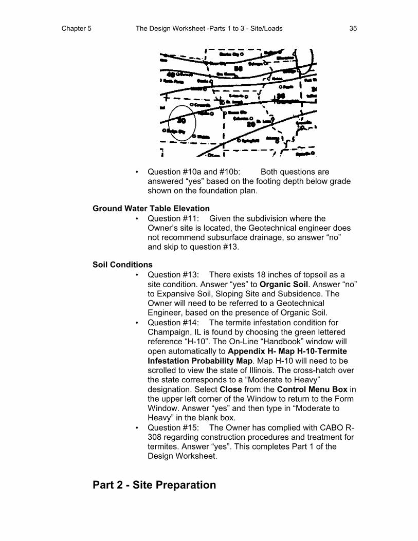
Chapter 5 The Design Worksheet -Parts 1 to 3 - Site/Loads 35
• Question #10a and #10b: Both questions are answered “yes” based on the footing depth below grade shown on the foundation plan.
Ground Water Table Elevation • Question #11: Given the subdivision where the
Owner’s site is located, the Geotechnical engineer does not recommend subsurface drainage, so answer “no” and skip to question #13.
Soil Conditions • Question #13: There exists 18 inches of topsoil as a
site condition. Answer “yes” to Organic Soil. Answer “no” to Expansive Soil, Sloping Site and Subsidence. The Owner will need to be referred to a Geotechnical Engineer, based on the presence of Organic Soil.
• Question #14: The termite infestation condition for Champaign, IL is found by choosing the green lettered reference “H-10”. The On-Line “Handbook” window will open automatically to Appendix H- Map H-10-Termite Infestation Probability Map. Map H-10 will need to be scrolled to view the state of Illinois. The cross-hatch over the state corresponds to a “Moderate to Heavy” designation. Select Close from the Control Menu Box in the upper left corner of the Window to return to the Form Window. Answer “yes” and then type in “Moderate to Heavy” in the blank box.
• Question #15: The Owner has complied with CABO R-308 regarding construction procedures and treatment for termites. Answer “yes”. This completes Part 1 of the Design Worksheet.
Part 2 - Site Preparation
36 The Design Worksheet - Parts 1 to 3 - Site/Loads Chapter 5
C. Select Part 2 - Site Preparation from the Worksheets pull-down menu. The next Part of the Form Window will appear on the screen. The User should be familiar with the style of the yes/no questions at this point. Answer the following as indicated: • Question #16 and #17: The subdivision surface drainage
plan and grading plan are provided; answer “yes” to both questions.
• Question #18: Footings will be placed on undisturbed soil below the topsoil. Answer “no”.
• Question #19: Finish grade elevation is not required unless in a flood plane. No answer is required. This completes Part 2 of the Design Worksheet.
Part 3 - Design loads
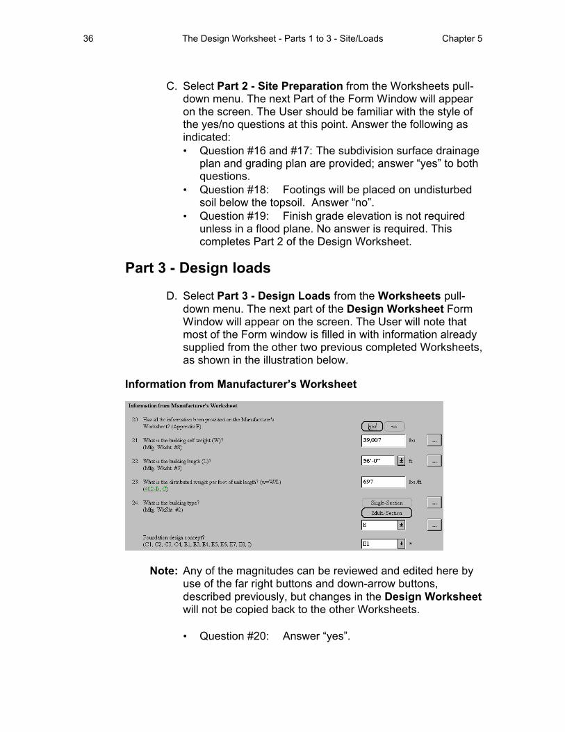
D. Select Part 3 - Design Loads from the Worksheets pull-down menu. The next part of the Design Worksheet Form Window will appear on the screen. The User will note that most of the Form window is filled in with information already supplied from the other two previous completed Worksheets, as shown in the illustration below.
Information from Manufacturer’s Worksheet
Note: Any of the magnitudes can be reviewed and edited here by use of the far right buttons and down-arrow buttons, described previously, but changes in the Design Worksheet will not be copied back to the other Worksheets.
• Question #20: Answer “yes”.
Chapter 5 The Design Worksheet -Parts 1 to 3 - Site/Loads 37
• Question #21: The superstructure selfweight (W) is the same total as calculated for the Manufacturer’s Worksheet, and is based on a continuous marriage wall without openings. This will be updated in this worksheet when the openings are located in plan.
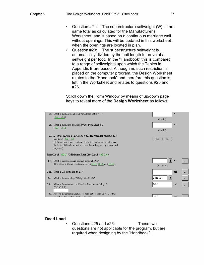
• Question #23: The superstructure selfweight is automatically divided by the unit length to arrive at a selfweight per foot. In the “Handbook” this is compared to a range of selfweights upon which the Tables in Appendix B are based. Although no such restriction is placed on the computer program, the Design Worksheet relates to the “Handbook” and therefore this question is left in the Worksheet and relates to questions #25 and #26.
Scroll down the Form Window by means of up/down page keys to reveal more of the Design Worksheet as follows:
Dead Load • Questions #25 and #26: These two
questions are not applicable for the program, but are required when designing by the ”Handbook”.
38 The Design Worksheet - Parts 1 to 3 - Site/Loads Chapter 5
• Question #27: This question is not applicable for the program, but it does apply if designing by the “Handbook”.
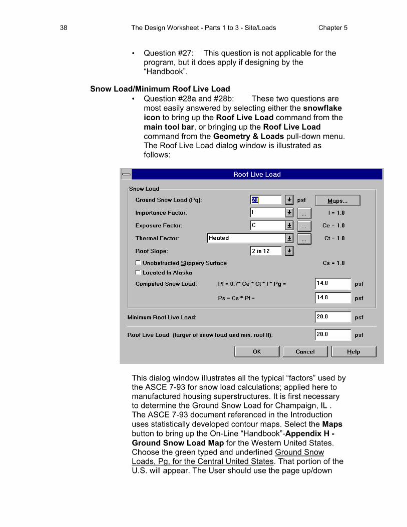
Snow Load/Minimum Roof Live Load • Question #28a and #28b: These two questions are
most easily answered by selecting either the snowflake icon to bring up the Roof Live Load command from the main tool bar, or bringing up the Roof Live Load command from the Geometry & Loads pull-down menu. The Roof Live Load dialog window is illustrated as follows:
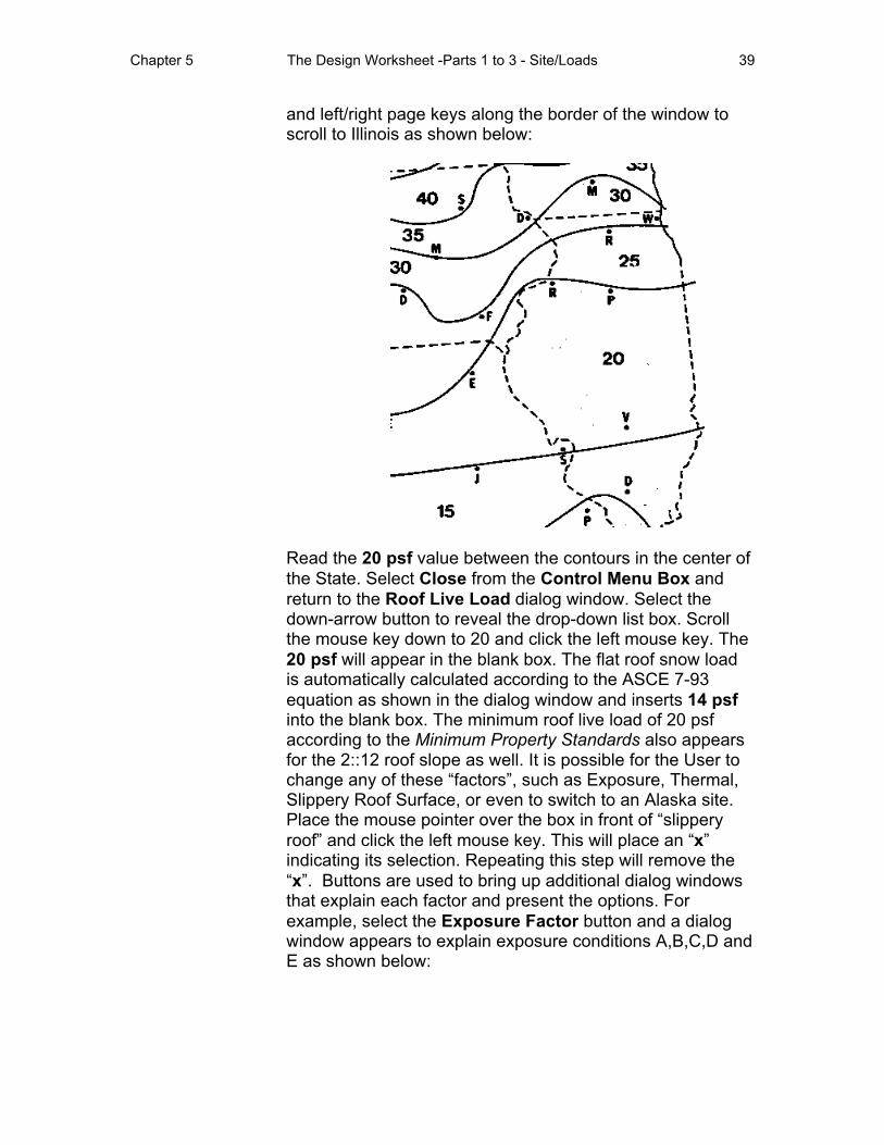
This dialog window illustrates all the typical “factors” used by the ASCE 7-93 for snow load calculations; applied here to manufactured housing superstructures. It is first necessary to determine the Ground Snow Load for Champaign, IL . The ASCE 7-93 document referenced in the Introduction uses statistically developed contour maps. Select the Maps button to bring up the On-Line “Handbook”-Appendix H -Ground Snow Load Map for the Western United States. Choose the green typed and underlined Ground Snow Loads, Pg, for the Central United States. That portion of the U.S. will appear. The User should use the page up/down
Chapter 5 The Design Worksheet -Parts 1 to 3 - Site/Loads 39
and left/right page keys along the border of the window to scroll to Illinois as shown below:
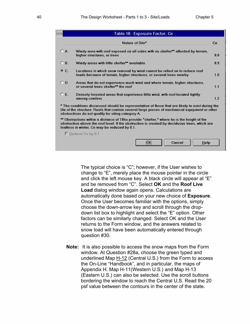
Read the 20 psf value between the contours in the center of the State. Select Close from the Control Menu Box and return to the Roof Live Load dialog window. Select the down-arrow button to reveal the drop-down list box. Scroll the mouse key down to 20 and click the left mouse key. The 20 psf will appear in the blank box. The flat roof snow load is automatically calculated according to the ASCE 7-93 equation as shown in the dialog window and inserts 14 psf into the blank box. The minimum roof live load of 20 psf according to the Minimum Property Standards also appears for the 2::12 roof slope as well. It is possible for the User to change any of these “factors”, such as Exposure, Thermal, Slippery Roof Surface, or even to switch to an Alaska site. Place the mouse pointer over the box in front of “slippery roof” and click the left mouse key. This will place an “x” indicating its selection. Repeating this step will remove the “x”. Buttons are used to bring up additional dialog windows that explain each factor and present the options. For example, select the Exposure Factor button and a dialog window appears to explain exposure conditions A,B,C,D and E as shown below:
40 The Design Worksheet - Parts 1 to 3 - Site/Loads Chapter 5
The typical choice is “C”; however, if the User wishes to change to “E”, merely place the mouse pointer in the circle and click the left mouse key. A black circle will appear at “E” and be removed from “C”. Select OK and the Roof Live Load dialog window again opens. Calculations are automatically done based on your new choice of Exposure. Once the User becomes familiar with the options, simply choose the down-arrow key and scroll through the drop-down list box to highlight and select the “E” option. Other factors can be similarly changed. Select OK and the User returns to the Form window, and the answers related to snow load will have been automatically entered through question #30.
Note: It is also possible to access the snow maps from the Form window. At Question #28a, choose the green typed and underlined Map H-12 (Central U.S.) from the Form to access the On-Line “Handbook”, and in particular, the maps of Appendix H. Map H-11(Western U.S.) and Map H-13 (Eastern U.S.) can also be selected. Use the scroll buttons bordering the window to reach the Central U.S. Read the 20 psf value between the contours in the center of the state.
Chapter 5 The Design Worksheet -Parts 1 to 3 - Site/Loads 41
Select Close from the Control Menu Box and return to the Form Window. Type in 20 psf in the blank box or use the down-arrow button to view the drop down list box and scroll down to highlight 20 psf. Clicking the left mouse key will automatically enter the number in the blank box. The next box automatically performs the multiplication by 0.7 and inserts 14 psf into the blank box. The minimum roof live load of 20 psf also appears for the 2::12 roof slope as well. The larger roof live load is 20 psf, rather than the 14 psf. The Form has automatically inserted the 20 in the blank box.
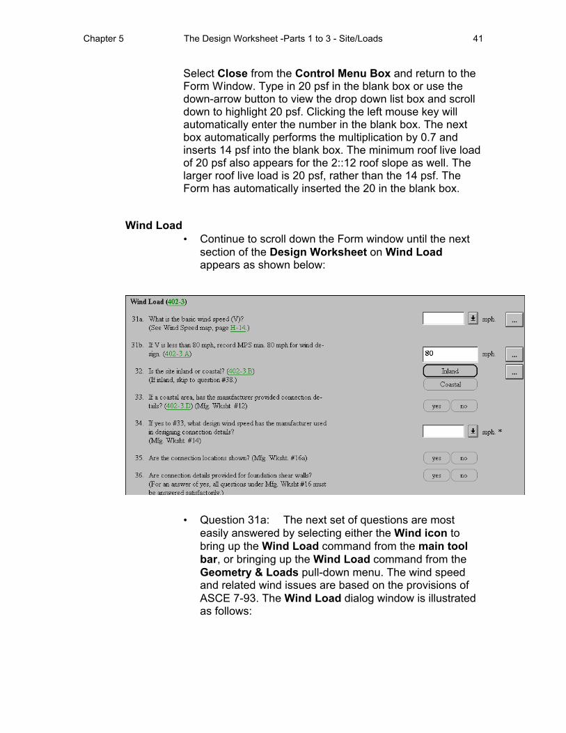
Wind Load • Continue to scroll down the Form window until the next
section of the Design Worksheet on Wind Load appears as shown below:
• Question 31a: The next set of questions are most easily answered by selecting either the Wind icon to bring up the Wind Load command from the main tool bar, or bringing up the Wind Load command from the Geometry & Loads pull-down menu. The wind speed and related wind issues are based on the provisions of ASCE 7-93. The Wind Load dialog window is illustrated as follows:
42 The Design Worksheet - Parts 1 to 3 - Site/Loads Chapter 5
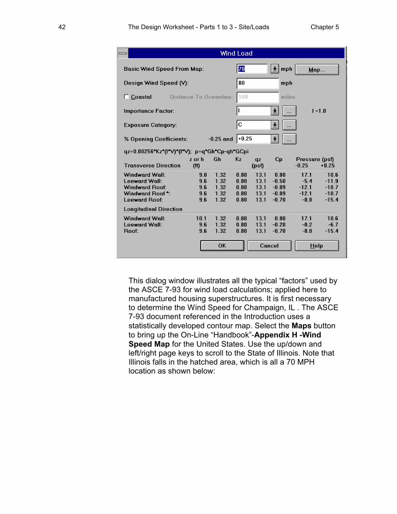
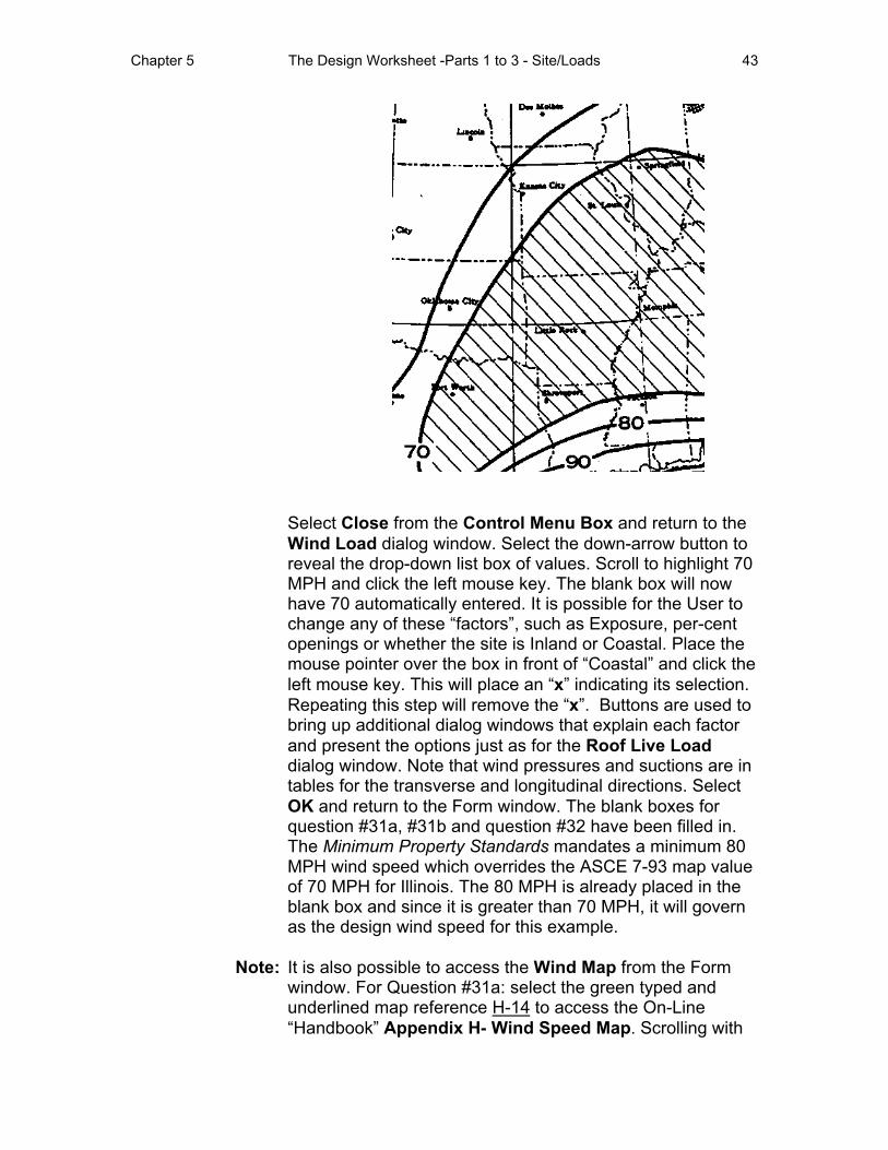
This dialog window illustrates all the typical “factors” used by the ASCE 7-93 for wind load calculations; applied here to manufactured housing superstructures. It is first necessary to determine the Wind Speed for Champaign, IL . The ASCE 7-93 document referenced in the Introduction uses a statistically developed contour map. Select the Maps button to bring up the On-Line “Handbook”-Appendix H -Wind Speed Map for the United States. Use the up/down and left/right page keys to scroll to the State of Illinois. Note that Illinois falls in the hatched area, which is all a 70 MPH location as shown below:
Chapter 5 The Design Worksheet -Parts 1 to 3 - Site/Loads 43
Select Close from the Control Menu Box and return to the Wind Load dialog window. Select the down-arrow button to reveal the drop-down list box of values. Scroll to highlight 70 MPH and click the left mouse key. The blank box will now have 70 automatically entered. It is possible for the User to change any of these “factors”, such as Exposure, per-cent openings or whether the site is Inland or Coastal. Place the mouse pointer over the box in front of “Coastal” and click the left mouse key. This will place an “x” indicating its selection. Repeating this step will remove the “x”. Buttons are used to bring up additional dialog windows that explain each factor and present the options just as for the Roof Live Load dialog window. Note that wind pressures and suctions are in tables for the transverse and longitudinal directions. Select OK and return to the Form window. The blank boxes for question #31a, #31b and question #32 have been filled in. The Minimum Property Standards mandates a minimum 80 MPH wind speed which overrides the ASCE 7-93 map value of 70 MPH for Illinois. The 80 MPH is already placed in the blank box and since it is greater than 70 MPH, it will govern as the design wind speed for this example.
Note: It is also possible to access the Wind Map from the Form window. For Question #31a: select the green typed and underlined map reference H-14 to access the On-Line “Handbook” Appendix H- Wind Speed Map. Scrolling with
44 The Design Worksheet - Parts 1 to 3 - Site/Loads Chapter 5
the page keys at the border of the screen is necessary to find Illinois as shown. Select Close from the Control Menu Box and return to the Form Window. Type in 70 in the blank box or use the down-arrow button to view the drop down list box and scroll down to highlight 70. It will automatically enter the blank box.
• Since the site is Inland question #33 through #37 can be skipped. If the User answered Coastal to question #32 then the Manufacturer of the superstructure must work with the owner to answer the questions up to #37.
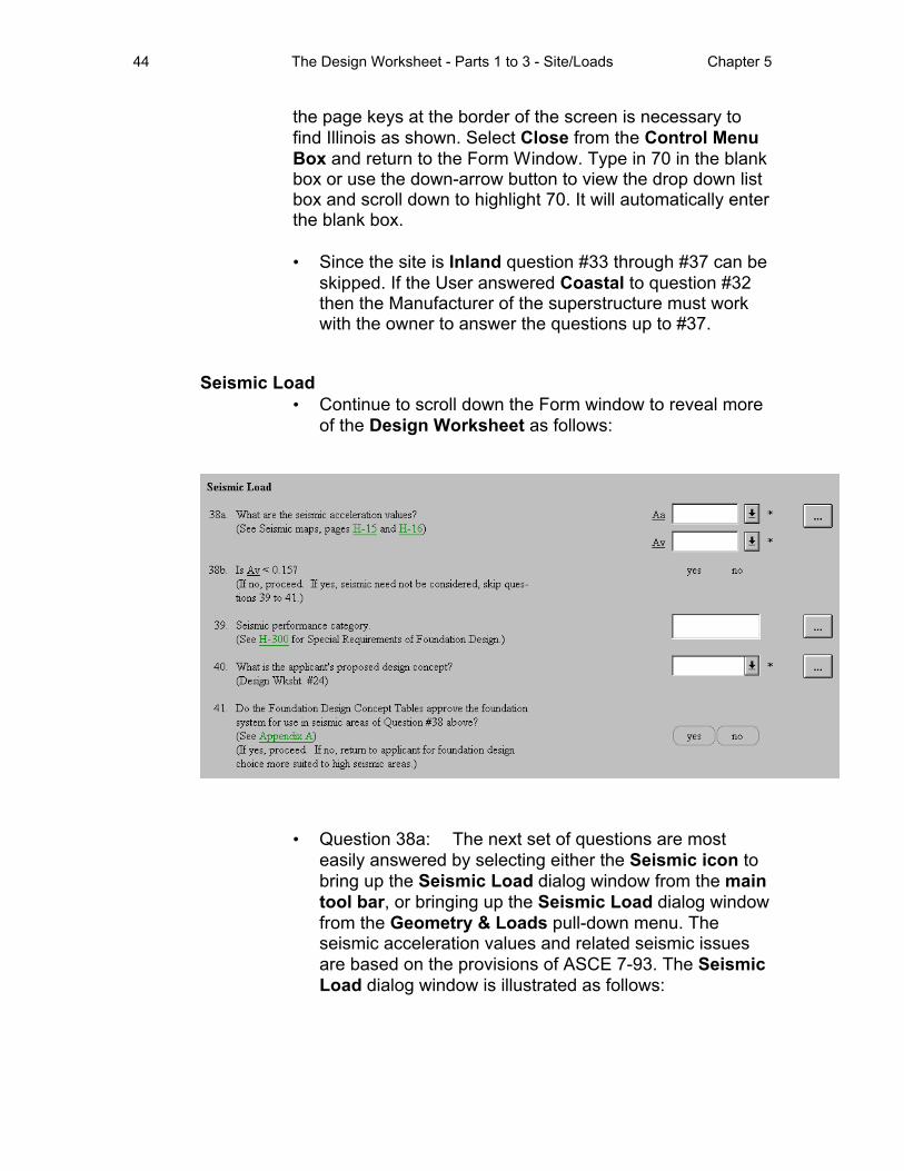
Seismic Load • Continue to scroll down the Form window to reveal more
of the Design Worksheet as follows:
• Question 38a: The next set of questions are most easily answered by selecting either the Seismic icon to bring up the Seismic Load dialog window from the main tool bar, or bringing up the Seismic Load dialog window from the Geometry & Loads pull-down menu. The seismic acceleration values and related seismic issues are based on the provisions of ASCE 7-93. The Seismic Load dialog window is illustrated as follows:
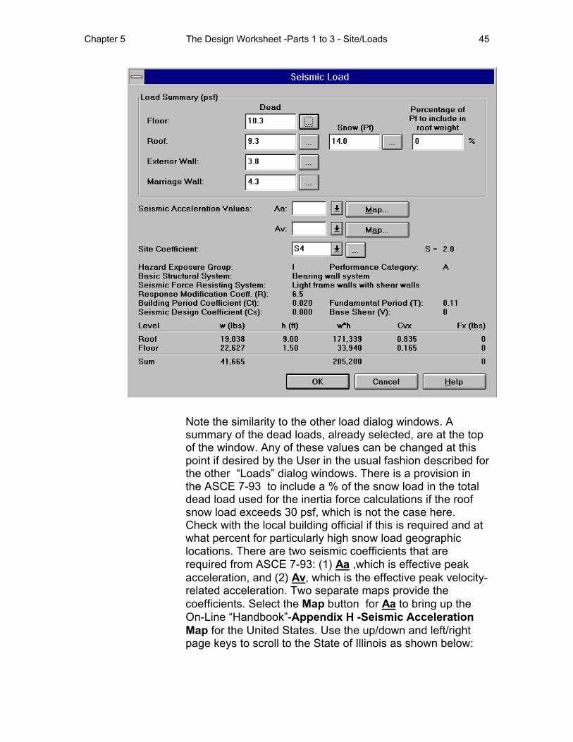
Chapter 5 The Design Worksheet -Parts 1 to 3 - Site/Loads 45
Note the similarity to the other load dialog windows. A summary of the dead loads, already selected, are at the top of the window. Any of these values can be changed at this point if desired by the User in the usual fashion described for the other “Loads” dialog windows. There is a provision in the ASCE 7-93 to include a % of the snow load in the total dead load used for the inertia force calculations if the roof snow load exceeds 30 psf, which is not the case here. Check with the local building official if this is required and at what percent for particularly high snow load geographic locations. There are two seismic coefficients that are required from ASCE 7-93: (1) Aa ,which is effective peak acceleration, and (2) Av, which is the effective peak velocity-related acceleration. Two separate maps provide the coefficients. Select the Map button for Aa to bring up the On-Line “Handbook”-Appendix H -Seismic Acceleration Map for the United States. Use the up/down and left/right page keys to scroll to the State of Illinois as shown below:
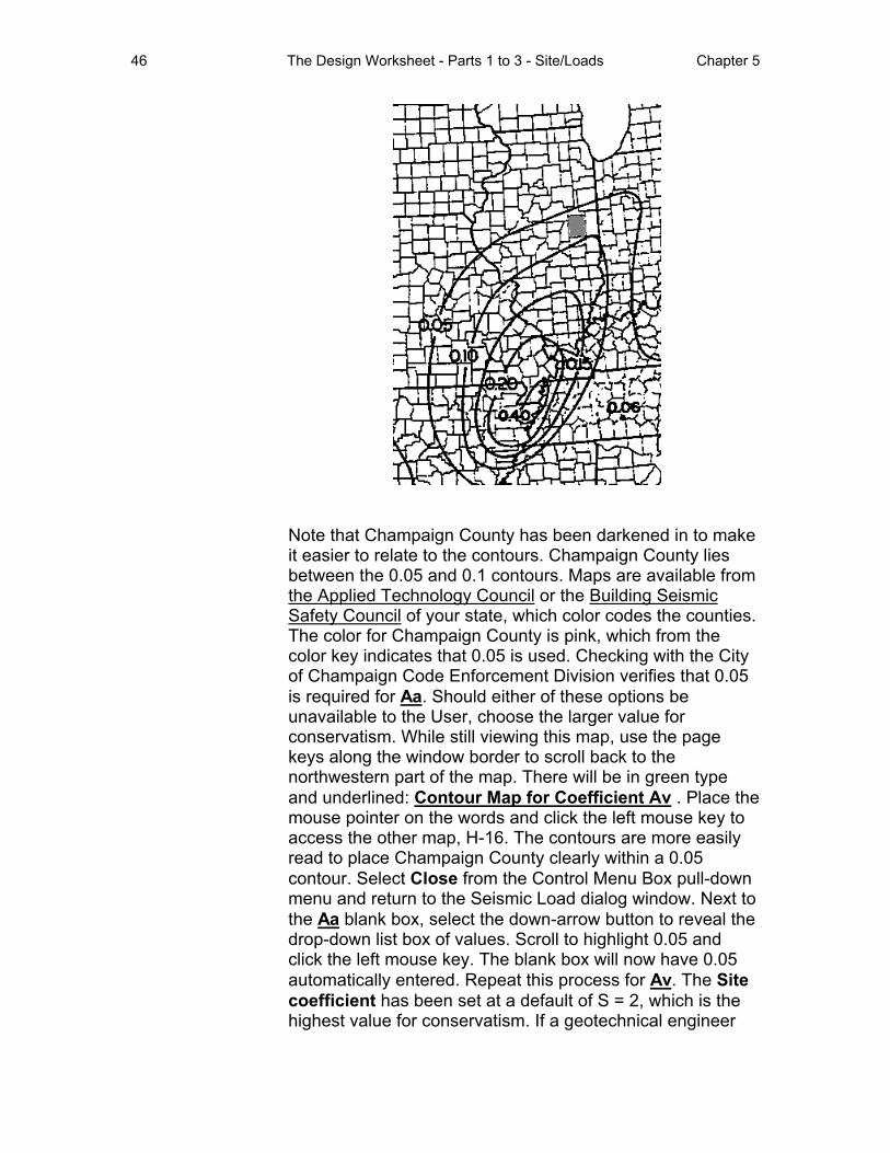
46 The Design Worksheet - Parts 1 to 3 - Site/Loads Chapter 5
Note that Champaign County has been darkened in to make it easier to relate to the contours. Champaign County lies between the 0.05 and 0.1 contours. Maps are available from the Applied Technology Council or the Building Seismic Safety Council of your state, which color codes the counties. The color for Champaign County is pink, which from the color key indicates that 0.05 is used. Checking with the City of Champaign Code Enforcement Division verifies that 0.05 is required for Aa. Should either of these options be unavailable to the User, choose the larger value for conservatism. While still viewing this map, use the page keys along the window border to scroll back to the northwestern part of the map. There will be in green type and underlined: Contour Map for Coefficient Av . Place the mouse pointer on the words and click the left mouse key to access the other map, H-16. The contours are more easily read to place Champaign County clearly within a 0.05 contour. Select Close from the Control Menu Box pull-down menu and return to the Seismic Load dialog window. Next to the Aa blank box, select the down-arrow button to reveal the drop-down list box of values. Scroll to highlight 0.05 and click the left mouse key. The blank box will now have 0.05 automatically entered. Repeat this process for Av. The Site coefficient has been set at a default of S = 2, which is the highest value for conservatism. If a geotechnical engineer
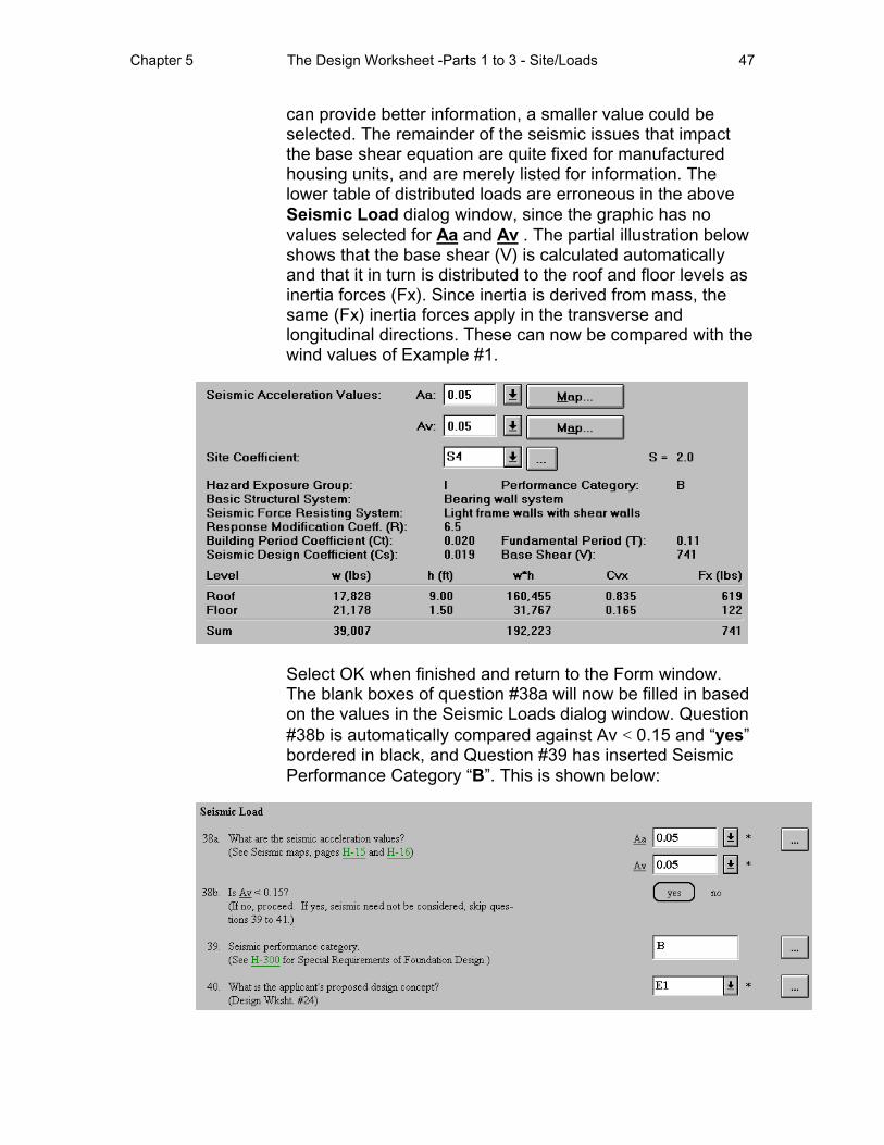
Chapter 5 The Design Worksheet -Parts 1 to 3 - Site/Loads 47
can provide better information, a smaller value could be selected. The remainder of the seismic issues that impact the base shear equation are quite fixed for manufactured housing units, and are merely listed for information. The lower table of distributed loads are erroneous in the above Seismic Load dialog window, since the graphic has no values selected for Aa and Av . The partial illustration below shows that the base shear (V) is calculated automatically and that it in turn is distributed to the roof and floor levels as inertia forces (Fx). Since inertia is derived from mass, the same (Fx) inertia forces apply in the transverse and longitudinal directions. These can now be compared with the wind values of Example #1.
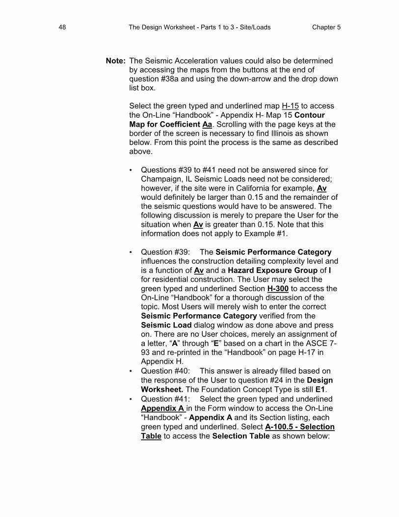
Select OK when finished and return to the Form window. The blank boxes of question #38a will now be filled in based on the values in the Seismic Loads dialog window. Question #38b is automatically compared against Av < 0.15 and “yes” bordered in black, and Question #39 has inserted Seismic Performance Category “B”. This is shown below:
48 The Design Worksheet - Parts 1 to 3 - Site/Loads Chapter 5
Note: The Seismic Acceleration values could also be determined by accessing the maps from the buttons at the end of question #38a and using the down-arrow and the drop down list box.
Select the green typed and underlined map H-15 to access the On-Line “Handbook” - Appendix H- Map 15 Contour Map for Coefficient Aa. Scrolling with the page keys at the border of the screen is necessary to find Illinois as shown below. From this point the process is the same as described above.
• Questions #39 to #41 need not be answered since for Champaign, IL Seismic Loads need not be considered; however, if the site were in California for example, Av would definitely be larger than 0.15 and the remainder of the seismic questions would have to be answered. The following discussion is merely to prepare the User for the situation when Av is greater than 0.15. Note that this information does not apply to Example #1.
• Question #39: The Seismic Performance Category influences the construction detailing complexity level and is a function of Av and a Hazard Exposure Group of I for residential construction. The User may select the green typed and underlined Section H-300 to access the On-Line “Handbook” for a thorough discussion of the topic. Most Users will merely wish to enter the correct Seismic Performance Category verified from the Seismic Load dialog window as done above and press on. There are no User choices, merely an assignment of a letter, “A” through “E” based on a chart in the ASCE 7-93 and re-printed in the “Handbook” on page H-17 in Appendix H.
• Question #40: This answer is already filled based on the response of the User to question #24 in the Design Worksheet. The Foundation Concept Type is still E1.
• Question #41: Select the green typed and underlined Appendix A in the Form window to access the On-Line “Handbook” - Appendix A and its Section listing, each green typed and underlined. Select A-100.5 - Selection Table to access the Selection Table as shown below:
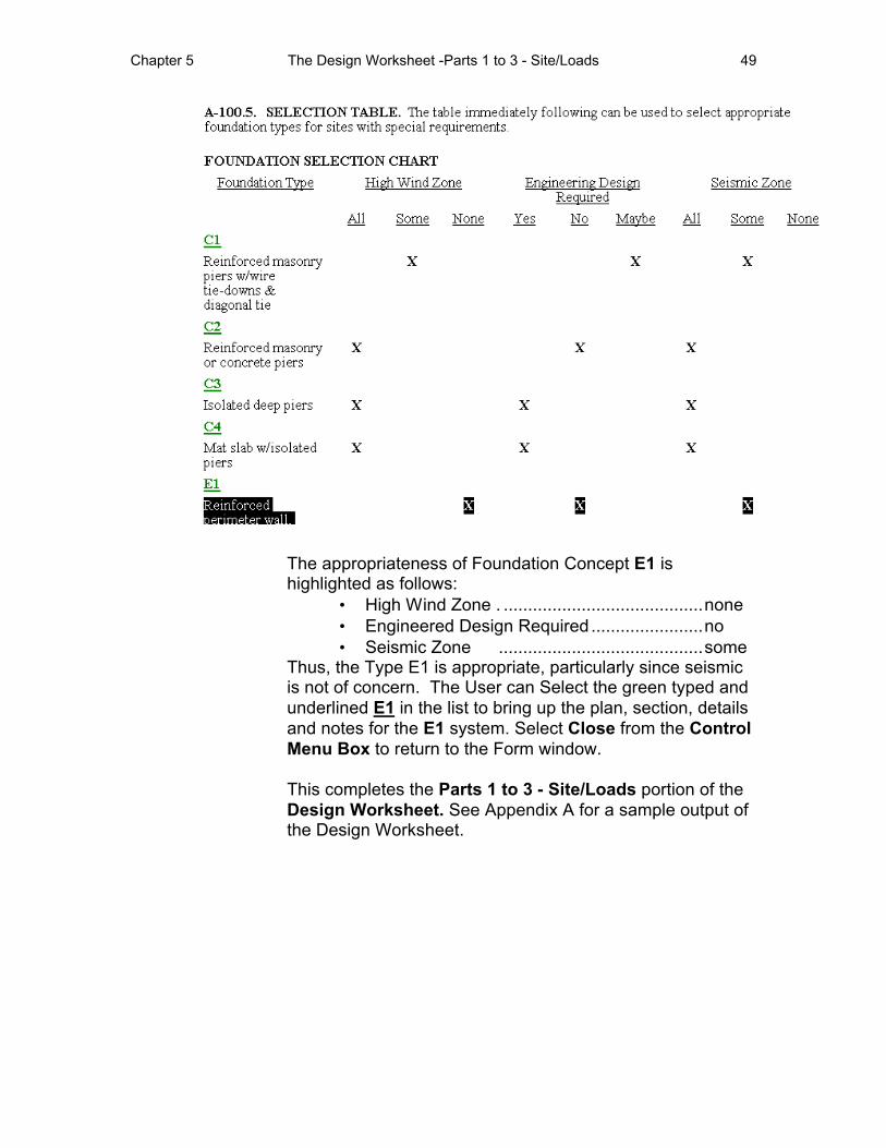
Chapter 5 The Design Worksheet -Parts 1 to 3 - Site/Loads 49
The appropriateness of Foundation Concept E1 is highlighted as follows:
• High Wind Zone . .........................................none • Engineered Design Required .......................no • Seismic Zone ..........................................some
Thus, the Type E1 is appropriate, particularly since seismic is not of concern. The User can Select the green typed and underlined E1 in the list to bring up the plan, section, details and notes for the E1 system. Select Close from the Control Menu Box to return to the Form window.
This completes the Parts 1 to 3 - Site/Loads portion of the Design Worksheet. See Appendix A for a sample output of the Design Worksheet.

50 The Design Worksheet - Parts 1 to 3 - Site/Loads Chapter 5