Embed Size (px)
Citation preview
Part#5500303-21 (Rev D)
Perle 10/100/1000 Ethernet
Media Converters
Installation Guide
S-1110
S-1110-SFP
S-1110-XT
Perle 10/100/1000 Ethernet Media Converter 2
Overview
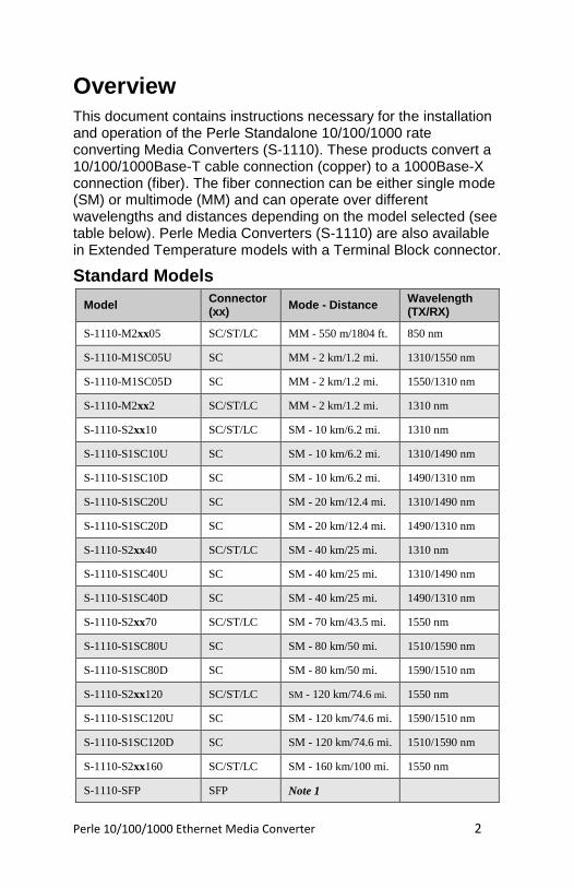
This document contains instructions necessary for the installation and operation of the Perle Standalone 10/100/1000 rate converting Media Converters (S-1110). These products convert a 10/100/1000Base-T cable connection (copper) to a 1000Base-X connection (fiber). The fiber connection can be either single mode (SM) or multimode (MM) and can operate over different wavelengths and distances depending on the model selected (see table below). Perle Media Converters (S-1110) are also available in Extended Temperature models with a Terminal Block connector.
Standard Models
Model Connector (xx)
Mode - Distance Wavelength (TX/RX)
S-1110-M2xx05 SC/ST/LC MM - 550 m/1804 ft. 850 nm
S-1110-M1SC05U SC MM - 2 km/1.2 mi. 1310/1550 nm
S-1110-M1SC05D SC MM - 2 km/1.2 mi. 1550/1310 nm
S-1110-M2xx2 SC/ST/LC MM - 2 km/1.2 mi. 1310 nm
S-1110-S2xx10 SC/ST/LC SM - 10 km/6.2 mi. 1310 nm
S-1110-S1SC10U SC SM - 10 km/6.2 mi. 1310/1490 nm
S-1110-S1SC10D SC SM - 10 km/6.2 mi. 1490/1310 nm
S-1110-S1SC20U SC SM - 20 km/12.4 mi. 1310/1490 nm
S-1110-S1SC20D SC SM - 20 km/12.4 mi. 1490/1310 nm
S-1110-S2xx40 SC/ST/LC SM - 40 km/25 mi. 1310 nm
S-1110-S1SC40U SC SM - 40 km/25 mi. 1310/1490 nm
S-1110-S1SC40D SC SM - 40 km/25 mi. 1490/1310 nm
S-1110-S2xx70 SC/ST/LC SM - 70 km/43.5 mi. 1550 nm
S-1110-S1SC80U SC SM - 80 km/50 mi. 1510/1590 nm
S-1110-S1SC80D SC SM - 80 km/50 mi. 1590/1510 nm
S-1110-S2xx120 SC/ST/LC SM - 120 km/74.6 mi. 1550 nm
S-1110-S1SC120U SC SM - 120 km/74.6 mi. 1590/1510 nm
S-1110-S1SC120D SC SM - 120 km/74.6 mi. 1510/1590 nm
S-1110-S2xx160 SC/ST/LC SM - 160 km/100 mi. 1550 nm
S-1110-SFP SFP Note 1
Perle 10/100/1000 Ethernet Media Converter 3
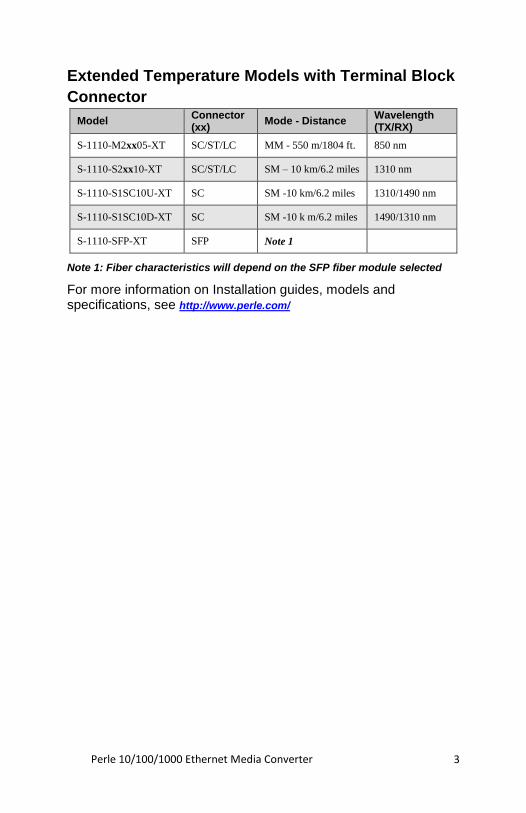
Extended Temperature Models with Terminal Block
Connector
Model Connector (xx)
Mode - Distance Wavelength (TX/RX)
S-1110-M2xx05-XT SC/ST/LC MM - 550 m/1804 ft. 850 nm
S-1110-S2xx10-XT SC/ST/LC SM – 10 km/6.2 miles 1310 nm
S-1110-S1SC10U-XT SC SM -10 km/6.2 miles 1310/1490 nm
S-1110-S1SC10D-XT SC SM -10 k m/6.2 miles 1490/1310 nm
S-1110-SFP-XT SFP Note 1
Note 1: Fiber characteristics will depend on the SFP fiber module selected
For more information on Installation guides, models and specifications, see http://www.perle.com/
Perle 10/100/1000 Ethernet Media Converter 4
Installation
The default DIP switch settings (all switches in the UP position) will work for most installations.
These are the steps required to configure the Perle S1110 Ethernet media converter:
1. Insert SFP Module.(SFP Model only)
2. Set the AUTO-MDIX jumper setting. (optional)
3. Set the DIP switch settings. (optional)
4. Attach the power cord strain relief clip. (optional)
5. Install and connect the fiber cable.
6. Install and connect the copper cable.
7. Power up the media converter.
Perle 10/100/1000 Ethernet Media Converter 5
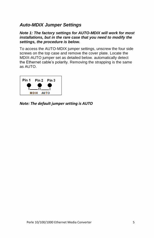
Auto-MDIX Jumper Settings
Note 1: The factory settings for AUTO-MDIX will work for most installations, but in the rare case that you need to modify the settings, the procedure is below.
To access the AUTO-MDIX jumper settings, unscrew the four side screws on the top case and remove the cover plate. Locate the MDIX-AUTO jumper set as detailed below. automatically detect the Ethernet cable’s polarity. Removing the strapping is the same as AUTO.
Note: The default jumper setting is AUTO

Perle 10/100/1000 Ethernet Media Converter 6
DIP Switches
The DIP switches are accessible through the opening in the side of the enclosure.
Note: All switch changes take effect immediately and will result in a link reset on both ports.
DIP Switch Settings
Auto Negotiation copper (Switch 1)
Switch Position Mode
Up (default) Auto
Down Off
Note 1: Auto negotiation should only be turned off, if the copper link partner does not support Auto Negotiation and fixed settings are required by the copper link partner.
Auto: When enabled, the media converter will negotiate with its link partner to determine the most optimal parameters for this connection. The S-1110 will advertise capabilities of 10,100 and 1000 Mbps, full and half duplex as well as pause, and remote fault capabilities to the link partner.
If the copper link partner does not support Auto negotiation, the S-1110 will parallel detect to 10 or 100 Mbps and force Half Duplex mode as per IEEE specifications.
Off: When the Auto Negotiation switch is set to the OFF position, the media converter will not negotiate the Ethernet parameters with the copper link partner. The parameters used by the media
Perle 10/100/1000 Ethernet Media Converter 7
converter will be determined by the Duplex (switch 4) and Speed (switch 5) DIP switch settings.
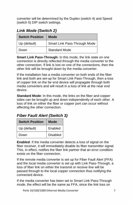
Link Mode (Switch 2)
Switch Position Mode
Up (default) Smart Link Pass-Through Mode
Down Standard Mode
Smart Link Pass-Through: In this mode, the link state on one connection is directly reflected through the media converter to the other connection. If link is lost on one of the connections, then the other link will be brought down by the media converter.
If the installation has a media converter on both ends of the fiber link and both are set-up for Smart Link Pass-Through, then a loss of copper link on the far end device will propagate through both media converters and will result in a loss of link at the near end device.
Standard Mode: In this mode, the links on the fiber and copper sides can be brought up and down independently of each other. A loss of link on either the fiber or copper port can occur without affecting the other connection.
Fiber Fault Alert (Switch 3)
Switch Position Mode
Up (default) Enabled
Down Disabled
Enabled: If the media converter detects a loss of signal on the fiber receiver, it will immediately disable its fiber transmitter signal. This, in effect, notifies the fiber link partner that an error condition exists on the fiber connection.
If the remote media converter is set up for Fiber Fault Alert (FFA) and the local media converter is set up with Link Pass-Through, a loss of fiber link on either the transmit or receive line will be passed through to the local copper connection thus notifying the connected device.
If the media converter has been set to Smart Link Pass-Through mode, the effect will be the same as FFA, since the link loss on
Perle 10/100/1000 Ethernet Media Converter 8
the fiber receiver will result in bringing down the copper link, which will in turn cause the transmit fiber link to be brought down.
Note: This feature only takes effect if Fiber Negotiation has been turned off.
Disabled: The media converter will not monitor for or generate Fiber Fault Alert.
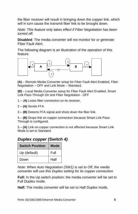
The following diagram is an illustration of the operation of this feature.
(A) – Remote Media Converter setup for Fiber Fault Alert Enabled, Fiber Negotiation – OFF and Link Mode – Standard.
(B) – Local Media Converter setup for Fiber Fault Alert Enabled, Smart
Link Pass-Through On and Fiber Negotiation - OFF
1 – (A) Loses fiber connection on its receiver.
2 – (A) Sends FFA.
3 – (B) Detects FFA signal and shuts down the fiber link.
4 – (B) Drops link on copper connection because Smart Link Pass-
Through is configured.
5 – (A) Link on copper connection is not affected because Smart Link Mode is set to Standard.
Duplex copper (Switch 4)
Switch Position Mode
Up (default) Full
Down Half
Note: When Auto Negotiation (SW1) is set to Off, the media converter will use this Duplex setting for its copper connection.
Full: In the Up switch position; the media converter will be set to Full Duplex mode.
Half: The media converter will be set to Half Duplex mode.
Perle 10/100/1000 Ethernet Media Converter 9
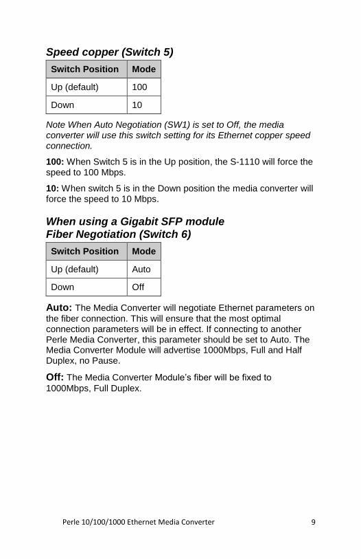
Speed copper (Switch 5)
Switch Position Mode
Up (default) 100
Down 10
Note When Auto Negotiation (SW1) is set to Off, the media converter will use this switch setting for its Ethernet copper speed connection.
100: When Switch 5 is in the Up position, the S-1110 will force the speed to 100 Mbps.
10: When switch 5 is in the Down position the media converter will force the speed to 10 Mbps.
When using a Gigabit SFP module Fiber Negotiation (Switch 6)
Switch Position Mode
Up (default) Auto
Down Off
Auto: The Media Converter will negotiate Ethernet parameters on
the fiber connection. This will ensure that the most optimal connection parameters will be in effect. If connecting to another Perle Media Converter, this parameter should be set to Auto. The Media Converter Module will advertise 1000Mbps, Full and Half Duplex, no Pause.
Off: The Media Converter Module’s fiber will be fixed to
1000Mbps, Full Duplex.
Perle 10/100/1000 Ethernet Media Converter 10
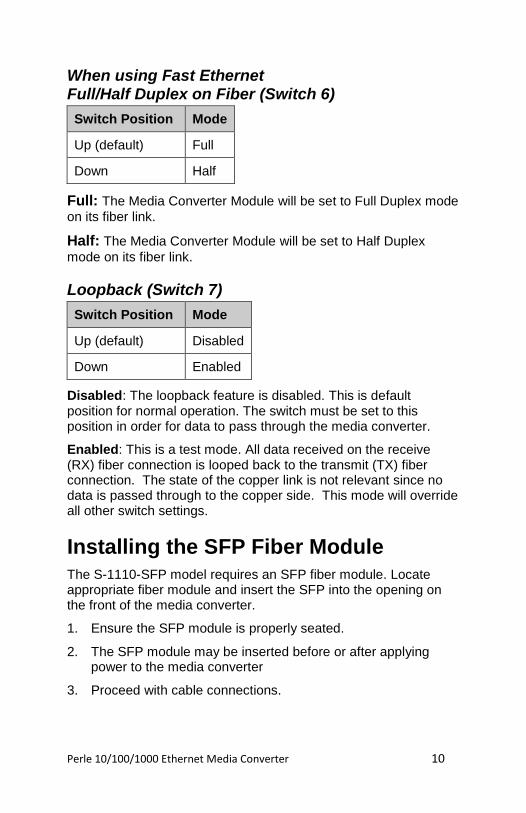
When using Fast Ethernet Full/Half Duplex on Fiber (Switch 6)
Switch Position Mode
Up (default) Full
Down Half
Full: The Media Converter Module will be set to Full Duplex mode
on its fiber link.
Half: The Media Converter Module will be set to Half Duplex
mode on its fiber link.
Loopback (Switch 7)
Switch Position Mode
Up (default) Disabled
Down Enabled
Disabled: The loopback feature is disabled. This is default position for normal operation. The switch must be set to this position in order for data to pass through the media converter.
Enabled: This is a test mode. All data received on the receive (RX) fiber connection is looped back to the transmit (TX) fiber connection. The state of the copper link is not relevant since no data is passed through to the copper side. This mode will override all other switch settings.
Installing the SFP Fiber Module
The S-1110-SFP model requires an SFP fiber module. Locate appropriate fiber module and insert the SFP into the opening on the front of the media converter.
1. Ensure the SFP module is properly seated.
2. The SFP module may be inserted before or after applying power to the media converter
3. Proceed with cable connections.
Perle 10/100/1000 Ethernet Media Converter 11
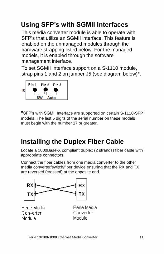
Using SFP’s with SGMII Interfaces This media converter module is able to operate with SFP’s that utilize an SGMII interface. This feature is enabled on the unmanaged modules through the hardware strapping listed below. For the managed models, it is enabled through the software management interface.
To set SGMII Interface support on a S-1110 module, strap pins 1 and 2 on jumper J5 (see diagram below)*.
*SFP’s with SGMII Interface are supported on certain S-1110-SFP
models. The last 5 digits of the serial number on these models must begin with the number 17 or greater.
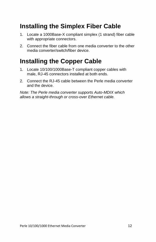
Installing the Duplex Fiber Cable
Locate a 1000Base-X compliant duplex (2 strands) fiber cable with appropriate connectors.
Connect the fiber cables from one media converter to the other media converter/switch/fiber device ensuring that the RX and TX are reversed (crossed) at the opposite end.
Perle 10/100/1000 Ethernet Media Converter 12
Installing the Simplex Fiber Cable
1. Locate a 1000Base-X compliant simplex (1 strand) fiber cable with appropriate connectors.
2. Connect the fiber cable from one media converter to the other media converter/switch/fiber device.
Installing the Copper Cable
1. Locate 10/100/1000Base-T compliant copper cables with male, RJ-45 connectors installed at both ends.
2. Connect the RJ-45 cable between the Perle media converter and the device.
Note: The Perle media converter supports Auto-MDIX which allows a straight-through or cross-over Ethernet cable.
Perle 10/100/1000 Ethernet Media Converter 13
Powering up the Perle Media Converter using the supplied Power Adapter
1. Connect the Perle supplied power adapter to the Media Converter.
2. Connect the power adapter to a power source.
3. Check that the PWR LED light is lit.
Terminal Block Connector
1. Ensure the Power Source is off.
2. Unplug the terminal block from the Media Converter
3. Strip insulator sheathing from both wires 5mm (3/16th inch) to expose the copper conductor wire.
4. Loosen the terminal block screws and connect Positive (+) wire to the left terminal. Connect the Negative (-) wire to the right terminal. Tighten Terminal screws (0.22Nm-0.25Nm torque).
5. Turn on power source.
6. Check that the PWR LED light is lit.
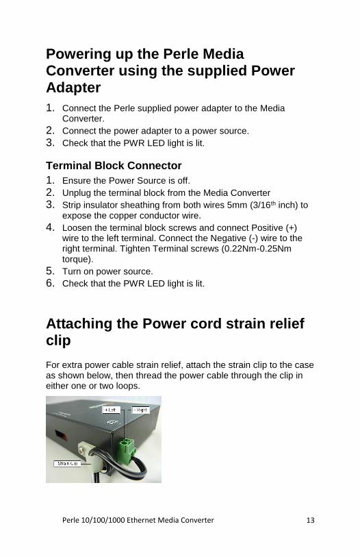
Attaching the Power cord strain relief clip
For extra power cable strain relief, attach the strain clip to the case as shown below, then thread the power cable through the clip in either one or two loops.
Perle 10/100/1000 Ethernet Media Converter 14
Operation
Status LED
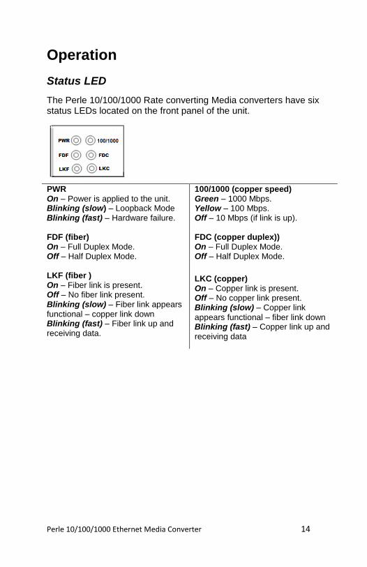
The Perle 10/100/1000 Rate converting Media converters have six status LEDs located on the front panel of the unit.
PWR On – Power is applied to the unit. Blinking (slow) – Loopback Mode Blinking (fast) – Hardware failure.
FDF (fiber) On – Full Duplex Mode. Off – Half Duplex Mode. LKF (fiber ) On – Fiber link is present. Off – No fiber link present. Blinking (slow) – Fiber link appears functional – copper link down Blinking (fast) – Fiber link up and receiving data.
100/1000 (copper speed) Green – 1000 Mbps. Yellow – 100 Mbps. Off – 10 Mbps (if link is up). FDC (copper duplex)) On – Full Duplex Mode. Off – Half Duplex Mode.
LKC (copper) On – Copper link is present. Off – No copper link present. Blinking (slow) – Copper link
appears functional – fiber link down Blinking (fast) – Copper link up and receiving data
Perle 10/100/1000 Ethernet Media Converter 15
Other Features
Auto-MDIX
Auto-MDIX (automatic medium-dependent interface crossover) detects the signalling on the 10/100/1000BASE-T interface to determine the type of cable connected (straight-through or crossover) and automatically configures the connection.
Error Recovery
In certain configurations, and under specific conditions where the media converter brings down a link to convey status, there is potential for a deadlock. Recovery is achieved by momentarily restoring the link to see if the original failure has been resolved. If it has not, the link will be forced down again, however if the original problem has been resolved, the link will be restored.
Pause (IEEE 802.3xy) Integrated Pause signalling is an IEEE feature that temporarily suspends data transmission between two devices in the event that one of the devices becomes overwhelmed. The Perle media converter can generate and respond to Pause messages.
Perle 10/100/1000 Ethernet Media Converter 16
Troubleshooting
General
• Ensure power is supplied to the media converter – use of the supplied power adapters is highly recommended.
• Ensure the remote device’s fiber connection type is compatible with the media converter. If using a simplex fiber connection, ensure that you have both an Upstream (U) and Downstream (D) media converter.
• Ensure all cabling is of the correct type and is in good working order.
• For duplex fiber connections, ensure the RX and TX has been reversed between the two media converters.
No connectivity
If unable to get full connectivity with all DIP switches in the UP position, this procedure is recommended for troubleshooting.
Method 1 1. Set the Link mode to Standard (SW2 – Down) on both media
converters. Leave all other switches in the Up position.
2. Connect the near end device to the copper connection. The LKC LED indicates good copper connection. If the LKC LED is not lit, then check the copper cable and the attached device.
3. Repeat for the far end media converter.
4. Connect the fiber cable to both media converters. The LKF LED indicates good fiber connection. If no LKF LED then check the fiber cabling. Ensure the transmitter and receiver pairs are crossed.
5. Return units to desired configuration.
Method 2:
The fiber connection can also be verified by configuring the remote media converter for loopback mode. The LKF LEDs on both media converters should be lit. Data should pass through the local converter, over the fiber connection to the remote media converter. At the remote media converter, the data will be looped back and passed through the fiber, back to the local converter and passed to the copper link.
Perle 10/100/1000 Ethernet Media Converter 17
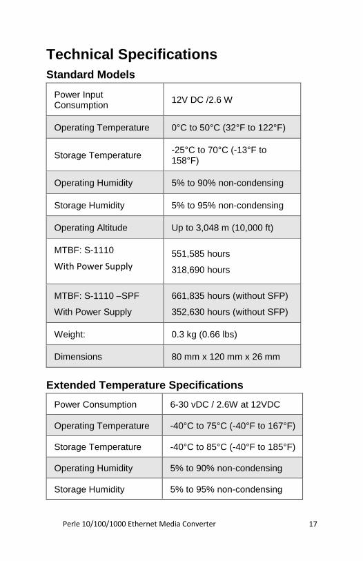
Technical Specifications
Standard Models
Power Input Consumption
12V DC /2.6 W
Operating Temperature 0°C to 50°C (32°F to 122°F)
Storage Temperature -25°C to 70°C (-13°F to 158°F)
Operating Humidity 5% to 90% non-condensing
Storage Humidity 5% to 95% non-condensing
Operating Altitude Up to 3,048 m (10,000 ft)
MTBF: S-1110
With Power Supply
551,585 hours
318,690 hours
MTBF: S-1110 –SPF
With Power Supply
661,835 hours (without SFP)
352,630 hours (without SFP)
Weight: 0.3 kg (0.66 lbs)
Dimensions 80 mm x 120 mm x 26 mm
Extended Temperature Specifications
Power Consumption 6-30 vDC / 2.6W at 12VDC
Operating Temperature -40°C to 75°C (-40°F to 167°F)
Storage Temperature -40°C to 85°C (-40°F to 185°F)
Operating Humidity 5% to 90% non-condensing
Storage Humidity 5% to 95% non-condensing
Perle 10/100/1000 Ethernet Media Converter 18
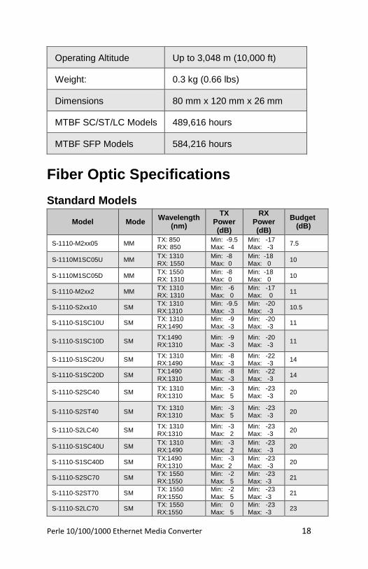
Operating Altitude Up to 3,048 m (10,000 ft)
Weight: 0.3 kg (0.66 lbs)
Dimensions 80 mm x 120 mm x 26 mm
MTBF SC/ST/LC Models 489,616 hours
MTBF SFP Models 584,216 hours
Fiber Optic Specifications
Standard Models
Model Mode Wavelength
(nm)
TX Power (dB)
RX Power (dB)
Budget (dB)
S-1110-M2xx05 MM TX: 850 RX: 850
Min: -9.5 Max: -4
Min: -17 Max: -3
7.5
S-1110M1SC05U MM TX: 1310 RX: 1550
Min: -8 Max: 0
Min: -18 Max: 0
10
S-1110M1SC05D MM TX: 1550 RX: 1310
Min: -8 Max: 0
Min: -18 Max: 0
10
S-1110-M2xx2 MM TX: 1310 RX: 1310
Min: -6 Max: 0
Min: -17 Max: 0
11
S-1110-S2xx10 SM TX: 1310 RX:1310
Min: -9.5 Max: -3
Min: -20 Max: -3
10.5
S-1110-S1SC10U SM TX: 1310 RX:1490
Min: -9 Max: -3
Min: -20 Max: -3
11
S-1110-S1SC10D SM TX:1490 RX:1310
Min: -9 Max: -3
Min: -20 Max: -3
11
S-1110-S1SC20U SM TX: 1310 RX:1490
Min: -8 Max: -3
Min: -22 Max: -3
14
S-1110-S1SC20D SM TX:1490 RX:1310
Min: -8 Max: -3
Min: -22 Max: -3
14
S-1110-S2SC40 SM TX: 1310 RX:1310
Min: -3 Max: 5
Min: -23 Max: -3
20
S-1110-S2ST40 SM TX: 1310 RX:1310
Min: -3 Max: 5
Min: -23 Max: -3
20
S-1110-S2LC40 SM TX: 1310 RX:1310
Min: -3 Max: 2
Min: -23 Max: -3
20
S-1110-S1SC40U SM TX: 1310 RX:1490
Min: -3 Max: 2
Min: -23 Max: -3
20
S-1110-S1SC40D SM TX:1490 RX:1310
Min: -3 Max: 2
Min: -23 Max: -3
20
S-1110-S2SC70 SM TX: 1550 RX:1550
Min: -2 Max: 5
Min: -23 Max: -3
21
S-1110-S2ST70 SM TX: 1550 RX:1550
Min: -2 Max: 5
Min: -23 Max: -3
21
S-1110-S2LC70 SM TX: 1550 RX:1550
Min: 0 Max: 5
Min: -23 Max: -3
23
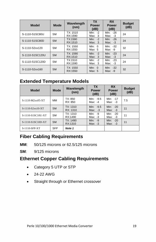
Perle 10/100/1000 Ethernet Media Converter 19
Model Mode Wavelength
(nm)
TX Power (dB)
RX Power (dB)
Budget (dB)
S-1110-S1SC80U SM TX: 1510 RX:1590
Min: -2 Max: 3
Min: -26 Max: -3
24
S-1110-S1SC80D SM TX:1590 RX:1510
Min: -2 Max: 3
Min: -26 Max: -3
24
S-1110-S2xx120 SM TX: 1550 RX:1550
Min: 0 Max: 5
Min: -32 Max: -9
32
S-1110-S1SC120U SM TX: 1590 RX:1510
Min: -2 Max: 3
Min: -23 Max: -3
24
S-1110-S1SC120D SM TX:1510 RX:1590
Min: -2 Max: 3
Min: -23 Max: -3
24
S-1110-S2xx160 SM TX: 1550 RX:1550
Min: 0 Max: 5
Min: -32 Max: -9
32
Extended Temperature Models
Model Mode Wavelength
(nm)
TX Power (dB)
RX Power (dB)
Budget (dB)
S-1110-M2xx05-XT MM TX: 850 RX: 850
Min: -9.5 Max: -4
Min: -17 Max: -3
7.5
S-1110-S2xx10-XT SM TX: 1310 RX: 1310
Min: -9.5 Max: -3
Min: -20 Max: -3
11
S-1110-S1SC10U-XT SM TX: 1310 RX:1490
Min: -9 Max: -3
Min: -20 Max: -3
11
S-1110-S1SC10D-XT SM TX: 1490 RX:1310
Min: -9 Max: -3
Min: -20 Max: -3
11
S-1110-SFP-XT SFP Note 1
Fiber Cabling Requirements
MM: 50/125 microns or 62.5/125 microns
SM: 9/125 microns
Ethernet Copper Cabling Requirements
• Category 5 UTP or STP
• 24-22 AWG
• Straight through or Ethernet crossover
Perle 10/100/1000 Ethernet Media Converter 20
Compliance Information
FCC This product has been found to comply with the limits for a Class A digital device, pursuant to Part 15 of the FCC rules. These limits are designed to provide reasonable protection against harmful interference when the equipment is operated in a commercial environment. This equipment generates, uses, and can radiate radio frequency energy and, if not installed and used in accordance with the instructions in this Guide, may cause harmful interference to radio communications. Operation of this equipment in a residential area is likely to cause harmful interference, in which case the user will be required to correct the interference at his/her own expense.
EN 55022, Class A WARNING This is a Class A product. In a domestic environment this product may cause radio interference in which case the user may be required to take adequate measures.
EN 55024, Class A Laser Safety – IEC 60825-1:2007
This product meets Class I Laser safety requirements per IEC-60825-1:2007 standard and complies with FDA/CDRH 21 CFR1040.10 and 21 CFR1040.11. WARNING: Visible and invisible laser radiation may be present when cables are not connected. Do not stare into the beam or view the beam directly with optical instruments. Failure to observe this warning could result in an eye injury or blindness. WARNING: Use of controls, adjustments or the performance of procedures other than those specified herein may result in hazardous radiation exposure.
Warranty / Registration Perle’s standard Lifetime Warranty provides customers with return to factory repairs for Perle products that fail under the conditions of the warranty coverage. Details can be found at:
http://www.perle.com/support_services/warranty.shtml
Contacting Technical Support Contact information for the Perle Technical Assistance Center (PTAC) can be found at the link below. A Technical Support Query may be made via this web page. www.perle.com/support_services/support_request.shtml
Copyright
© 2017 Perle Systems Limited All rights reserved. No part of this document may be reproduced or used in any form without written permission from Perle Systems.