Embed Size (px)
Citation preview
@PerkinsTechnical Data
®
4000 Series 4006-23TAG2A4006-23TAG3ADiesel Engine - ElectropaK
Basic technical data
Number of cylinders . ... ... ... ... ... ... ... ... ... ... ... ... ... ... ... ... ... ... ... ... ...6Cylinder arrangement ... ... ... ... ... ... ... ... ... ... ... ... ... ... ... . Vertical, In lineCycle. ... ... ... ... ... ... ... ... ... ... ... ... ... ... ... . 4 stroke, compression ignitionInduction system... ... ... ... ... ... ... ... ... ... ... ... ... ... ... ... ... .. TurbochargedCompression ratio ... ... ... ... ... ... ... ... ... ... ... ... ... ... ... ... . 13.6:1 nominalBore .. ... ... ... ... ... ... ... ... ... ... ... ... ... ... ... ... ... ... ... ... ... ... ... ... 160 mmStroke .. ... ... ... ... ... ... ... ... ... ... ... ... ... ... ... ... ... ... ... ... ... ... ... 190 mmCubic capacity .. ... ... ... ... ... ... ... ... ... ... ... ... ... ... ... ... ... ... . 22,921 litresDirection of rotation .. ... ... ... ... ... ... ... ...Anti-clockwise viewed on flywheelFiring order ... ... ... ... ... ... ... ... ... ... ... ... ... ... ... ... ... ... ... ...1, 5, 3, 6, 2, 4Cylinder 1 . ... ... ... ... ... ... ... ... ... ... ... ... ... ... ... ... ...furthest from flywheelTotal weight of Electrounit (engine only)-dry ... ... ... ... ... ... ... ... ... ... ... ... ... ... ... ... ... ... ... ... ... ... ... ... ... 2524 kg-wet... ... ... ... ... ... ... ... ... ... ... ... ... ... ... ... ... ... ... ... ... ... ... ... ... 2663 kgOverall dimensions-height... ... ... ... ... ... ... ... ... ... ... ... ... ... ... ... ... ... ... ... ... ... ... ..1964 mm-length... ... ... ... ... ... ... ... ... ... ... ... ... ... ... ... ... ... ... ... ... ... ... ..3027 mm-width ... ... ... ... ... ... ... ... ... ... ... ... ... ... ... ... ... ... ... ... ... ... ... ..1706 mmMoment of inertiaEngine .. ... ... ... ... ... ... ... ... ... ... ... ... ... ... ... ... ... ... ... ... ... ... .4,59 kgm²Flywheel ... ... ... ... ... ... ... ... ... ... ... ... ... ... ... ... ... ... ... ... ... ... .6,02 kgm²Cyclic irregularity for engine/flywheel (prime power):
RatingsSteady state speed stability at constant load ... ... ... ... ... ... ... ... ... ± 0.25%Electrical rating are based on average alternator efficiency and are for guidance only (0.8 power factor being used).
Operating pointEngine speed ... ... ... ... ... ... ... ... ... ... ... ... ... ... ... ... ..1500/1800 rev/minStatic injection timing . ... ... ... ... ... ... ... ... ... ... ... See engine number plateCooling water exit temperature .. ... ... ... ... ... ... ... ... ... ... ... ... ..98 °C Max.
Fuel dataTo conform to BS2869 class A2.
PerformanceEstimated sound pressure level (Temperate):- 1500 rev/min ... ... ... ... ... ... ... ... ... ... ... ... ... ... ... ... ... ... ... ... ..106 dBA- 1800 rev/min ... ... ... ... ... ... ... ... ... ... ... ... ... ... ... ... ... ... ... ... ..111 dBAEstimated sound pressure level (Tropical):- 1500 rev/min ... ... ... ... ... ... ... ... ... ... ... ... ... ... ... ... ... ... ... ... ..107 dBA
Note: All data based on operation to ISO 3046/1, BS 5514 and DIN 6271 standard reference conditions.
For engines operating in ambient conditions other than the standard reference conditions stated below, a suitable de-rate must be applied. De-rate tables for increased ambient temperature and/or altitude are available, please contact Perkins Applications Department.
Test ConditionsAir temperature. . ... ... ... ... ... ... ... ... ... ... ... ... ... ... ... ... ... ... ... ... .. 25 °CBarometric pressure... ... ... ... ... ... ... ... ... ... ... ... ... ... ... ... ... ... .. 100 kPaRelative humidity ... ... ... ... ... ... ... ... ... ... ... ... ... ... ... ... ... ... ... ... ... .30%Air inlet restriction at maximum power (nominal) ... ... ... ... ... ... ... ... 2,5 kPaExhaust back pressure (nominal) .. ... ... ... ... ... ... ... ... ... ... ... ... ... 3,0 kPaFuel temperature (inlet pump) ... ... ... ... ... ... ... ... ... ... ... ..58 °C maximumFor test conditions relevant to data on load acceptance, refer to Perkins Applications Department.
TAG2A TAG3A
1500 rev/min 1:67 1:62
1800 rev/min 1:105 1:97
General installation 4006-23TAG2A - Temperate
Designation Units50 Hz 1500 rev/min 60 Hz 1800 rev/min
Baseload power
Prime Power Standby power Baseload
powerPrime Power
Standby power
Gross engine power kWm 521 646 711 554 684 759
Fan power kWm 22 38
Net engine power kWm 499 624 689 516 646 721
BMEP gross kPa 1812 2247 2473 1606 1983 2200
Combustion air flow m³/min 60 64 71 62 65 73
Exhaust gas temperature max. after turbo °C 430
Exhaust gas flow (max) m³/min 180 190
Boost pressure ration - 3,0 3,4 3,6 3,2 3,4 3,6
Mechanical efficiency % 90
Overall thermal efficiency % 43 42 41 41,5 41 40
Friction power and pumping losses kWm 70 75
Mean piston speed m/s 9,5 11,4
Engine coolant flow l/s 10 12
Cooling fan airflow m³/min 1200 1320
Typical Genset electrical output0.8pf 25 °C (100 kPa)
kVA 592 740 817 612 766 855
kWe 474 592 654 490 613 684
Assumed alternator efficiency % 95 94
General installation
4006-23TAG2A - Tropical
4006-23TAG3A - Temperate
Designation Units50 Hz 1500 rev/min 60 Hz 1800 rev/min
Baseload power
Prime Power Standby power Baseload
powerPrime Power
Standby power
Gross engine power kWm 521 646 711 554 684 759
Fan power kWm 26 44
Net engine power kWm 495 620 685 510 640 715
BMEP gross kPa 1812 2247 2473 1606 1983 2200
Combustion air flow m³/min 60 64 71 62 65 73
Exhaust gas temperature max. after turbo °C 430
Exhaust gas flow (max) m³/min 180 190
Boost pressure ration - 3,0 3,4 3,6 3,2 3,4 3,6
Mechanical efficiency % 90
Overall thermal efficiency % 43 42 41 41,5 41 40
Friction power and pumping losses kWm 70 75
Mean piston speed m/s 9,5 11,4
Engine coolant flow l/s 10 12
Cooling fan airflow m³/min 1200 1320
Typical Genset electrical output0.8pf 25 °C (100 kPa)
kVA 585 730 800 600 750 844
kWe 468 584 640 480 600 675
Assumed alternator efficiency % 95 94
Designation Units50 Hz 1500 rev/min 60 Hz 1800 rev/min
Baseload power
Prime Power Standby power Baseload
powerPrime Power
Standby power
Gross engine power kWm 566 705 786 614 759 839
Fan power kWm 22 38
Net engine power kWm 544 683 764 576 721 801
BMEP gross kPa 1969 2452 2734 1780 2200 2432
Combustion air flow m³/min 60 69 73 68 76 78
Exhaust gas temperature max. after turbo
°C 500
Exhaust gas flow (max) m³/min 193 209
Boost pressure ration - 3,1 3,5 3,8 3,35 3,6 3,79
Mechanical efficiency % 90
Overall thermal efficiency % 43 41 40 41,5 40,5 39,5
Friction power and pumping losses kWm 70 75
Mean piston speed m/s 9,5 11,4
Engine coolant flow l/s 10 12
Cooling fan airflow m³/min 1200 1320
Typical Genset electrical output0.8pf 25 °C (100 kPa)
kVA 645 810 906 683 855 950
kWe 516 648 725 547 684 760
Assumed alternator efficiency % 95 95
General installation
4006-23TAG3A - Tropical
Rating Definitions
Baseload PowerUnlimited hours usage with an average load factor of 100% of the published Baseload Power. No overload is permitted on Baseload Power.
Prime PowerUnlimited hours usage with an average load factor of 80% of the published Prime Power over each 24 hours period. A 10% overload is available for 1 hour in every 12 hours operation.
Standby PowerLimited to 500 hours annual usage with an average load factor of 80% of the published Standby Power rating over each 24 hour period. Up to 300 hours of annual usage may be run continuously. No overload is permitted on Standby Power.
Designation Units50 Hz 1500 rev/min 60 Hz 1800 rev/min
Baseload power
Prime Power Standby power Baseload
powerPrime Power
Standby power
Gross engine power kWm 566 705 786 614 759 839
Fan power kWm 26 44
Net engine power kWm 540 679 760 570 715 795
BMEP gross kPa 1969 2452 2734 1780 2200 2432
Combustion air flow m³/min 60 69 73 68 76 78
Exhaust gas temperature max. after turbo °C 500
Exhaust gas flow (max) m³/min 193 209
Boost pressure ration - 3,1 3,5 3,8 3,35 3,6 3,79
Mechanical efficiency % 90
Overall thermal efficiency % 43 41 40 41,5 40,5 39,5
Friction power and pumping losses kWm 70 75
Mean piston speed m/s 9,5 11,4
Engine coolant flow l/s 10 12
Cooling fan airflow m³/min 1200 1320
Typical Genset electrical output0.8pf 25 °C (100 kPa)
kVA 640 800 900 675 844 938
kWe 512 640 720 540 675 750
Assumed alternator efficiency % 95 95
Energy balance
4006-23TAG2A - Temperate
4006-23TAG2A - Tropical
4006-23TAG3A - Temperate
4006-23TAG3A - Tropical
Note: ½ TA Luft figures have been developed to comply with ½ TA Luft as 1986 with 2000 mg/m³ NOx 5% O2 limits for power generation engines.
Designation Units
50 Hz 1500 rev/min½ TA Luft
50 Hz 1500 rev/minBest SFC 1800 rev/min
Baseload Power
Prime Power
Standby Power
Baseload Power
Prime Power
Standby Power
Baseload Power
Prime Power
Standby Power
Energy in fuel kW 1365 1721 1880 1293 1595 1764 1457 1824 2033
Energy in power output (gross) kW 521 646 711 521 646 711 554 684 759
Energy to cooling fan kW 22 22 38
Energy in power output (net) kW 499 624 689 499 624 689 516 640 721
Energy to exhaust kW 450 610 657 415 500 540 543 649 695
Energy to coolant and oil kW 200 221 240 170 191 240 157 220 260
Energy to radiation kW 40 55 76 52 64 71 58 73 81
Energy to charge coolers kW 154 189 196 135 194 202 145 204 238
Designation Units
50 Hz 1500 rev/min½ TA Luft
50 Hz 1500 rev/minBest SFC 1800 rev/min
Baseload Power
Prime Power
Standby Power
Baseload Power
Prime Power
Standby Power
Baseload Power
Prime Power
Standby Power
Energy in fuel kW 1365 1721 1880 1293 1595 1764 1457 1824 2033
Energy in power output (gross) kW 521 646 711 521 646 711 554 684 759
Energy to cooling fan kW 26 26 44
Energy in power output (net) kW 495 620 685 495 620 685 509 639 714
Energy to exhaust kW 450 610 657 415 500 540 543 649 695
Energy to coolant and oil kW 200 221 240 170 191 240 157 220 260
Energy to radiation kW 40 55 76 52 64 71 58 73 81
Energy to charge coolers kW 154 189 196 135 194 202 145 204 238
Designation Units
50 Hz 1500 rev/min½ TA Luft
50 Hz 1500 rev/minBest SFC 1800 rev/min
Baseload Power
Prime Power
Standby Power
Baseload Power
Prime Power
Standby Power
Baseload Power
Prime Power
Standby Power
Energy in fuel kW 1470 1926 2154 1390 1749 1970 1598 1995 2258
Energy in power output (gross) kW 366 705 786 566 705 786 614 759 839
Energy to cooling fan kW 22 22 38
Energy in power output (net) kW 544 683 764 544 683 764 576 721 801
Energy to exhaust kW 480 665 741 429 500 565 530 635 759
Energy to coolant and oil kW 210 280 315 190 280 310 225 309 330
Energy to radiation kW 59 77 86 56 70 79 64 80 90
Energy to charge coolers kW 155 199 226 149 194 230 165 212 240
Designation Units
50 Hz 1500 rev/min½ TA Luft
50 Hz 1500 rev/minBest SFC 1800 rev/min
Baseload Power
Prime Power
Standby Power
Baseload Power
Prime Power
Standby Power
Baseload Power
Prime Power
Standby Power
Energy in fuel kW 1470 1926 2154 1390 1749 1970 1598 1995 2258
Energy in power output (gross) kW 566 705 786 566 705 786 614 759 839
Energy to cooling fan kW 26 26 44
Energy in power output (net) kW 540 679 760 540 679 760 569 714 794
Energy to exhaust kW 480 665 741 429 500 565 530 635 759
Energy to coolant and oil kW 210 280 315 190 280 310 225 309 330
Energy to radiation kW 59 77 86 56 70 79 64 80 90
Energy to charge coolers kW 155 199 226 149 194 230 165 212 240
Cooling systemRecommended coolant: 50% inhibited ethylene glycol or 50% inhibited propylene glycol and 50% clean fresh water. For combined heat and power systems and where there is no likelihood of ambient temperature below 10 °C, then clean ‘soft’ water may be used, treated with 1% by volume of Perkins inhibitor in the cooling system. The inhibitor is available in 1 litre bottles from Perkins.Nominal jacket water pressure in crankcase. ... ... ... ... ... 170 kPaMaximum top temperature (standby) ... ... ... ... ... ... ... ... ... 98 °CMaximum static pressure head on pump .. ... ... ... ... ... ... ... ... 7 mDraw down capacity .. ... ... ... ... ... ... ... ... ... ... ... ... ... ... .22 litresMaximum permissible restriction to coolant pump flow. ... .. 20 kPaThermostat operating range.. ... ... ... ... ... ... ... ... ... ... .71 - 85 °CAmbient cooling clearance (open ElectropaK prime power) based on air temp at fan 3 °C above ambient.
Temperate
Tropical
The above information at 1500 rev/min applies for ½ TA Luft and Best SFC ratings.
RadiatorRadiator face area. ... ... ... ... ... ... ... ... ... ... ... ... ... ... ...2,569 m°Rows and materials... ... ... ... ... ... ... ... ... ... 3 rows of brass tubesGills per inch and material- jacket water. ... ... ... ... ... ... ... ... ... ... ... Copper fin at 14 gills/in- charge air section ... ... ... ... ... ... ... ... ... Copper fin at 10 gills/inWidth and height of matrix- height .. ... ... ... ... ... ... ... ... ... ... ... ... ... ... ... ... ... ... .. 1600 mm- width ... ... ... ... ... ... ... ... ... ... ... ... ... ... ... ... ... ... ... .. 1606 mmWeight (dry) radiator . ... ... ... ... ... ... ... ... ... ... ... ... ... ... .. 570 kgTotal coolant capacity ... ... ... ... ... ... ... ... ... ... ... ... ... ...105 litresPressure cap setting . ... ... ... ... ... ... ... ... ... ... ... ... ... ... .. 70 kPa
Charge cooler, integral with radiatorFace area.. ... ... ... ... ... ... ... ... ... ... ... ... ... ... ... ... ... ... 1,622 m²
Coolant pumpSpeed and method of drive... ... ... ... ... ... ... .1.4 x e rev/min Gear
FanType .. ... ... ... ... ... ... ... ... ... ... ... ... ... ... ... ... ...Engine mountedSpeed:- 1500 ... ... ... ... ... ... ... ... ... ... ... ... ... ... ... ... ... ... 1170 rev/min- 1800 ... ... ... ... ... ... ... ... ... ... ... ... ... ... ... ... ... ... 1404 rev/minDiameter ... ... ... ... ... ... ... ... ... ... ... ... ... ... ... ... ... ... ... ... 1,2 mNumber of blades - Temperate... ... ... ... ... ... ... ... ... ... ... ... ... ... ... ... ... ... ... ... .. 6- Tropical ... ... ... ... ... ... ... ... ... ... ... ... ... ... ... ... ... ... ... ... ... .. 8Material . ... ... ... ... ... ... ... ... ... ... ... ... ... ... ... ... ... ... ... ... .SteelDrive ratio.. ... ... ... ... ... ... ... ... ... ... ... ... ... ... ... ... ... ... . 0.78 : 1
Lubrication systemRecommended lubricating oil to conform with the specification of API CG4 15W/40Lubricating oil capacity:- sump maximum ... ... ... ... ... ... ... ... ... ... ... ... ... ... .. 113,4 litres- sump minimum. ... ... ... ... ... ... ... ... ... ... ... ... ... ... ... 90,7 litresLubrication oil pressure at rated speedMinimum. ... ... ... ... ... ... ... ... ... ... ... ... ... ... ... ... ... ... ...240 kPaOil relief values open.. ... ... ... ... ... ... ... ... ... ... ... ... ... ...300 kPaOil filter spacing.. ... ... ... ... ... ... ... ... ... ... ... ... ... ... . 40 micronsSump drain plug tapping size . ... ... ... ... ... ... ... ... ... ... ... ... ... G1Oil pump speed and method of drive . ... ... ... 1.4 x e rev/min, gearOil pump flow:- 1500 rev/min ... ... ... ... ... ... ... ... ... ... ... ... ... ... ... ... .. 3,7 litres- 1800 rev/min ... ... ... ... ... ... ... ... ... ... ... ... ... ... ... ... .. 4,4 litresOil consumption as a precentage of full load fuel consumption less than ... ... ... ... ... ... ... ... ... ... ... ... ... ... ... ... ... ... ... ... ... ..0.25%
Normal operating anglesFront and rear. ... ... ... ... ... ... ... ... ... ... ... ... ... ... ... ... ... ... ... 5°Side tilt ... ... ... ... ... ... ... ... ... ... ... ... ... ... ... ... ... ... ... ... ... .. 10°
Electrical systemType ... ... ... ... ... ... ... ... ... ... ... ... ... ... ... ... ... ... Insulated returnAlternator ... .. 40 amps at 28 volts, stabilised output at 20 °C ambientStarter motor .. ... ... ... ... ... ... ... ... ... ... ... ... ... ... ... ... ... .7,5 kWNumber of teeth on flywheel... ... ... ... ... ... ... ... ... ... ... ... ... ..190Number of teeth on starter motoer . ... ... ... ... ... ... ... ... ... ... ... 12Minimum cranking speed ... ... ... ... ... ... ... ... ... ... ... . 120 rev/minPull in current of starter motor solenoid.. ... ... .30 amps at 24 voltsHold in current of starter motor solenoid ... ... ...9 amps at 24 voltsEngine stop solenoid .. ... ... ... ... ... ... ... ... ... ... ... ... ... ... 24 voltsPull in current of stop solenoid ... ... ... ... ... ... .60 amps at 24 volts
Starting requirements
Notes:
The battery capacity is defined by the 20 hour rate at 0 °C
The oil specification should be for the minimum ambient temperature as the oil will not be warned by the immersion heater
The breakaway current is dependant on the battery capacity available. Cables should be capable of handling the transient currrent which may be up to double the steady cranking current.
Maximum additional restriction (duct allowance) to cooling airflow. (TAG2A and TAG3A standby power) and resultant minimum airflow
Ambient clearance: 50% Glycol
Duct allowancemm H2O Min airflow m³/sec
rev/min rev/min rev/min
1500 1800 1500 1800 1500 1800
36 °C 39 °C 25 25 13 16
Maximum additional restriction (duct allowance) to cooling airflow. (TAG2A and TAG3A standby power) and resultant minimum airflow
Ambient clearance: inhibited coolant
Duct allowancemm H2O Min airflow m³/sec
rev/min rev/min rev/min
1500 1800 1500 1800 1500 1800
50 °C 50 °C 13 20 20 22
Coolant jacket data Units 1500rev/min
1800 rev/min
Coolant flow l/s 10 12
Coolant exit temperature (max) °C 98 98
Coolant entry temperature (min) °C 70 70
Temperature range
To 10 °C (50 °F)
Oli: CG4 15w/40Starter: 1 x 24 voltsBattery: 2 x 12v x Ah 143max. breakaway:- current 1000 amps- cranking current 600 amps- aids Not necessary
Fuel systemRecommended fuel ... . To conform to BS2869 1998 Class A1, A2Type of injection system ... ... ... ... ... ... ... ... ... ... .Direct injectionFuel injector ... ... ... ... ... ... ... ... ... ... ... ... Combined unit injectorFuel injector pressure.. ... ... ... ... ... 220 ATS (NOP) 1400 bar maximum operating pressureDelivery:- 1500 rev/min ... ... ... ... ... ... ... ... ... ... ... ... ... ... . 660 litres/hour- 1800 rev/min ... ... ... ... ... ... ... ... ... ... ... ... ... ... . 810 litres/hourFuel delivery pump pressure.. ... ... ... ... ... ... ... ... ... ... ... 300 kPaFuel lift pump maximum suction head ... ... ... ... ... ... ... ... ... 2.5 mFuel return maximum pressure head... ... ... ... ... ... ... ... ... ... ... ... ... ... .. 3m above fuel delivery pumpFuel filter spacing... ... ... ... ... ... ... ... ... ... ... ... ... ... ...10 micronsGovernor type ... ... ... ... ... ... ... ... ... ... ... ... ... ... ... ... Electrionic
Fuel consumption gross (½ TA Luft)Temperate and Tropical
Fuel consumption gross (Best SFC)Temperate and Tropical
Induction systemMaximum air intake restriction of engine:- clean filter.. ... ... ... ... ... ... ... ... ... ... ... ... ... ... ... . 127 mm H2O- dirty filter ... ... ... ... ... ... ... ... ... ... ... ... ... ... ... ... .. 380 mm H2O- air filter type... ... ... ... ... ... ... ... ... ... ... ... ... ... ... ... ..dry - paper
Exhaust systemExhaust outlet size (internal) ... ... ... ... ... ... ... ... ... . 2 x 152,4 mmExhaust back pressure for total system:- TAG2A .. ... ... ... ... ... ... ... ... ... ... ... ... ... ... ... ... .. 610 mm H2O- TAG3A .. ... ... ... ... ... ... ... ... ... ... ... ... ... ... ... ... .. 610 mm H2OFor recommended pipe sizes see the Installation Manual.
Engine mountingMaximum additional load applies to flywheel due to all rotating components. ... ... ... ... ... ... ... ... ... ... ... ... ... ... ... ... ... ... 650 kgPosition of engine centre of gravity (wet):- forward of the rear face of the crankcase.. ... ... ... ... ... ..625 mm- above the crankdshaft centre line . ... ... ... ... ... ... ... ... ..140 mmg/kW/h l/h
4006-23TAG2A 1500 1800 1500 1800
Standby 213 226 176 200
Prime 213 221 159 176
Baseload 205 210 127 135
75% Prime 210 212 119 129
50% Prime 208 212 79 90
4006-23TAG3A
Standby 222 230 203 224
Prime 214 226 175 200
Baseload 207 213 139 152
75% Prime 213 214 132 145
50% Prime 213 205 88 96
g/kW/h l/h
4006-23TAG2A 1500 1800 1500 1800
Standby 210 226 173 199
Prime 209 222 157 177
Baseload 210 210 127 136
75% Prime 211 212 121 129
50% Prime 213 212 83 90
4006-23TAG3A
Standby 212 230 194 224
Prime 210 226 172 200
Baseload 208 213 137 152
75% Prime 210 214 130 144
50% Prime 213 205 90 96
4006-23TA
G2A
and
4006-23TA
G3A
- Left h
and
side view
EAR FACE
YWHEEL HOUSING
ENGINE
MOUNTINGS
220
EXHAUST OUTLETS
NOTE: CUSTOMER CONNECTION
MUST BE SUFFICIENTLY SUPPORTED
TO ENSURE THAT NO LOAD IS
PLACED ON THE TURBOCHARGERS
EAR FACE
RANKCASE
CENTRE-LINE
CRANKSHAFT
EAR FACE
YWHEEL HOUSING
TIMING MARK
VIEWING HOLE
624
2106
OVERALL3027
1380.5
1650.5
73025
352
1493
R
FL
FRONT FACE
CRANKCASE
25
( )1310.5
CENTRE OF GRAVITY
ENGINE AND RADIATOR
(WET)
R
C
ENGINE BREATHER OUTLET TO
SUIT ø50.8 (2") INSIDE HOSE
ENGINE PROTECTION
SWITCH
FAN BELT
TENSIONER SCREW
FAN GUARD BELT GUARD
AND DAMPER GUARD
SHOWN CHAIN-DOTTED
LEFT SIDE ELEVATION
R
FL
AIR FLOW
FUEL COOLER
CONNCTIONS G3/4
CENTRE OF GRAVITY
ENGINE ONLY (WET)
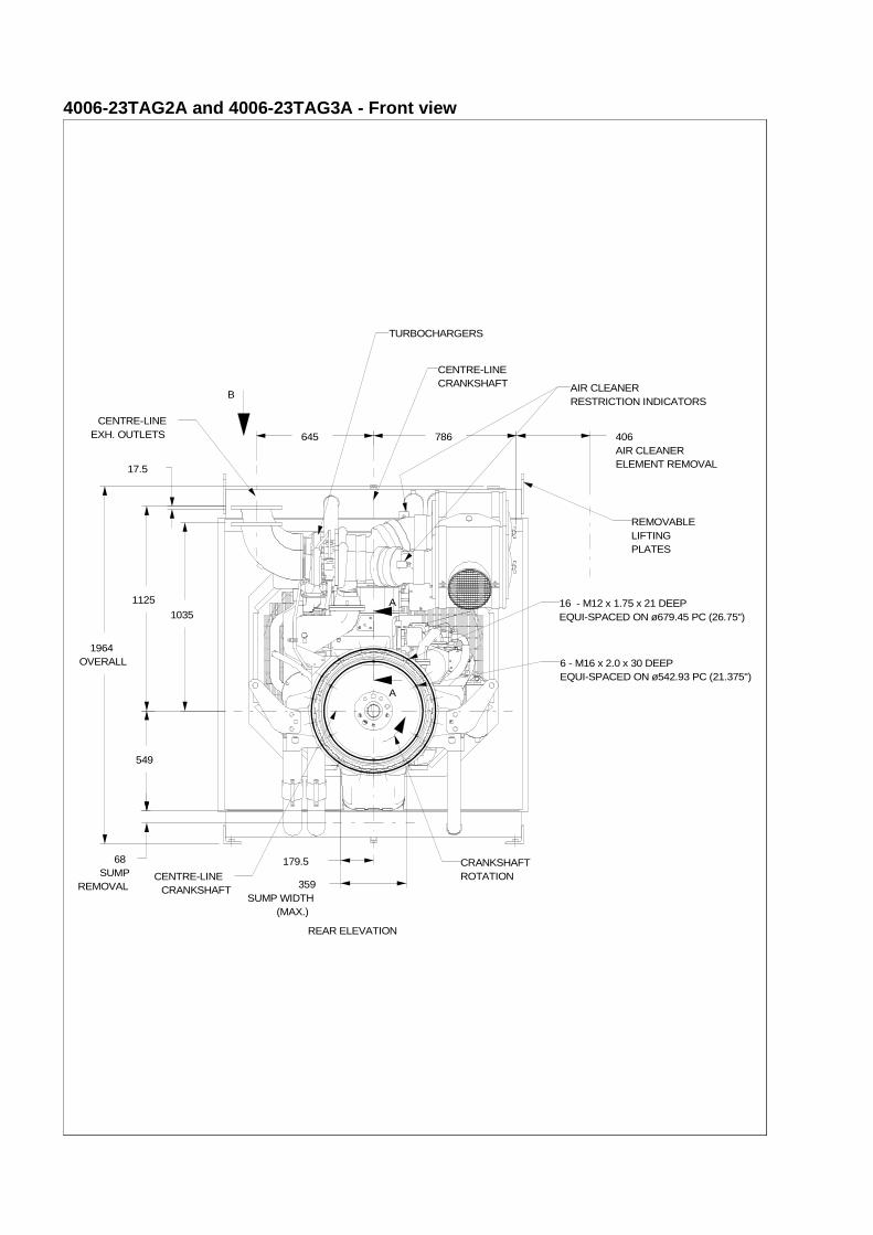
4006-23TAG2A and 4006-23TAG3A - Front view
A
A
SUMP WIDTH(MAX.)
359
AIR CLEANERELEMENT REMOVAL
406
SUMPREMOVAL
68 179.5
OVERALL1964
1035
1125
17.5
645 786
549
B
CRANKSHAFTROTATION
16 - M12 x 1.75 x 21 DEEPEQUI-SPACED ON ø679.45 PC (26.75")
6 - M16 x 2.0 x 30 DEEPEQUI-SPACED ON ø542.93 PC (21.375")
AIR CLEANERRESTRICTION INDICATORS
CENTRE-LINEEXH. OUTLETS
CENTRE-LINECRANKSHAFT
CENTRE-LINECRANKSHAFT
REAR ELEVATION
TURBOCHARGERS
REMOVABLELIFTINGPLATES
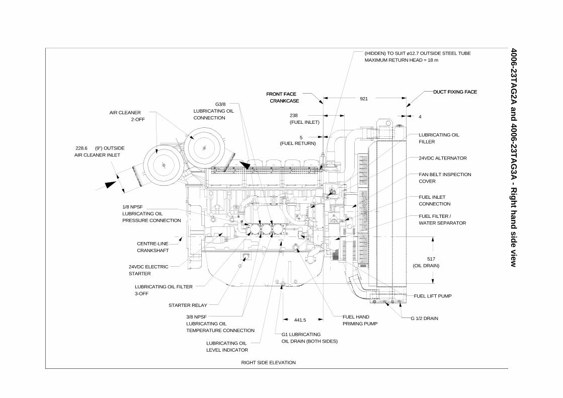
4006-23TA
G2A
and
4006-23TA
G3A
- Rig
ht h
and
side view
(OIL DRAIN)
517
DUCT FIXING FACE
4
EN) TO SUIT ø12.7 OUTSIDE STEEL TUBE
MUM RETURN HEAD = 18 m
LUBRICATING OIL
FILLER
FUEL FILTER /
WATER SEPARATOR
24VDC ALTERNATOR
FUEL LIFT PUMP
FUEL INLET
CONNECTION
DUCT FIXING FACE
G 1/2 DRAIN
FAN BELT INSPECTION
COVER
(9") OUTSIDE
AIR CLEANER INLET
228.6(FUEL RETURN)
5
(FUEL INLET)
238
441.5
921FRONT FACE
CRANKCASE
(HIDD
MAXI
FUEL HAND
PRIMING PUMP
LUBRICATING OIL
LEVEL INDICATOR
G1 LUBRICATING
OIL DRAIN (BOTH SIDES)
LUBRICATING OIL FILTER
3-OFF
STARTER RELAY
24VDC ELECTRIC
STARTER
3/8 NPSF
LUBRICATING OIL
TEMPERATURE CONNECTION
1/8 NPSF
LUBRICATING OIL
PRESSURE CONNECTION
G3/8
LUBRICATING OIL
CONNECTION
FRONT FACE
CRANKCASE
AIR CLEANER
2-OFF
RIGHT SIDE ELEVATION
CENTRE-LINE
CRANKSHAFT
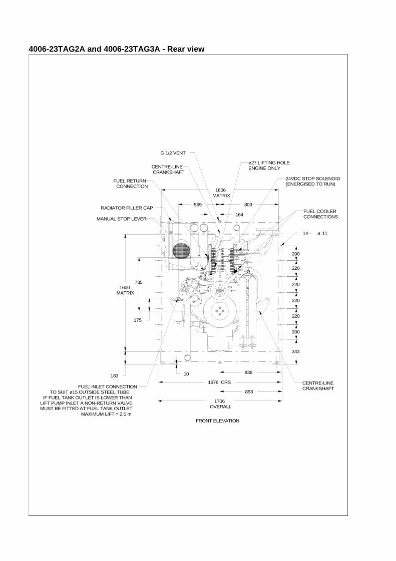
4006-23TAG2A and 4006-23TAG3A - Rear view
A
200
220
220
220
220
200
CRS1676
MATRIX1600
MATRIX1606
10183
343
OVERALL1706
164
569
175
735
838
853
803
14 - ø 11
CENTRE-LINE CRANKSHAFT
CENTRE-LINECRANKSHAFT
RADIATOR FILLER CAP
FUEL INLET CONNECTIONTO SUIT ø15 OUTSIDE STEEL TUBE
IF FUEL TANK OUTLET IS LOWER THANLIFT PUMP INLET A NON-RETURN VALVEMUST BE FITTED AT FUEL TANK OUTLET
MAXIMUM LIFT = 2.5 m
FUEL RETURNCONNECTION
ø27 LIFTING HOLEENGINE ONLY
FRONT ELEVATION
MANUAL STOP LEVER
24VDC STOP SOLENOID(ENERGISED TO RUN)
G 1/2 VENT
FUEL COOLERCONNECTIONS
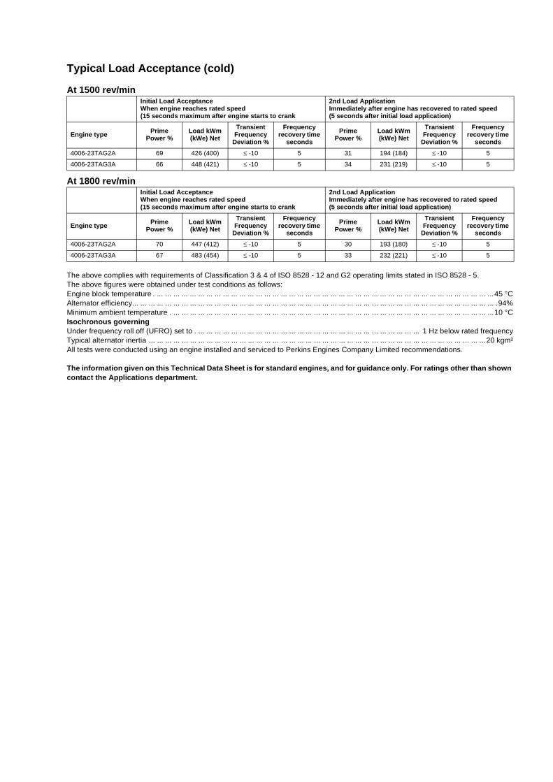
Typical Load Acceptance (cold)
At 1500 rev/min
At 1800 rev/min
The above complies with requirements of Classification 3 & 4 of ISO 8528 - 12 and G2 operating limits stated in ISO 8528 - 5.The above figures were obtained under test conditions as follows:Engine block temperature . ... ... ... ... ... ... ... ... ... ... ... ... ... ... ... ... ... ... ... ... ... ... ... ... ... ... ... ... ... ... ... ... ... ... ... ... ... ... ... ... ...45 °CAlternator efficiency... ... ... ... ... ... ... ... ... ... ... ... ... ... ... ... ... ... ... ... ... ... ... ... ... ... ... ... ... ... ... ... ... ... ... ... ... ... ... ... ... ... ... ... .94%Minimum ambient temperature . ... ... ... ... ... ... ... ... ... ... ... ... ... ... ... ... ... ... ... ... ... ... ... ... ... ... ... ... ... ... ... ... ... ... ... ... ... ... ...10 °CIsochronous governingUnder frequency roll off (UFRO) set to . ... ... ... ... ... ... ... ... ... ... ... ... ... ... ... ... ... ... ... ... ... ... ... ... ... ... ... 1 Hz below rated frequencyTypical alternator inertia ... ... ... ... ... ... ... ... ... ... ... ... ... ... ... ... ... ... ... ... ... ... ... ... ... ... ... ... ... ... ... ... ... ... ... ... ... ... ... ... ...20 kgm²All tests were conducted using an engine installed and serviced to Perkins Engines Company Limited recommendations.
The information given on this Technical Data Sheet is for standard engines, and for guidance only. For ratings other than shown contact the Applications department.
Initial Load Acceptance When engine reaches rated speed(15 seconds maximum after engine starts to crank
2nd Load ApplicationImmediately after engine has recovered to rated speed(5 seconds after initial load application)
Engine type Prime Power %
Load kWm (kWe) Net
Transient Frequency
Deviation %
Frequency recovery time
seconds
Prime Power %
Load kWm (kWe) Net
Transient Frequency
Deviation %
Frequency recovery time
seconds
4006-23TAG2A 69 426 (400) ≤ -10 5 31 194 (184) ≤ -10 5
4006-23TAG3A 66 448 (421) ≤ -10 5 34 231 (219) ≤ -10 5
Initial Load Acceptance When engine reaches rated speed(15 seconds maximum after engine starts to crank
2nd Load ApplicationImmediately after engine has recovered to rated speed(5 seconds after initial load application)
Engine type Prime Power %
Load kWm (kWe) Net
Transient Frequency
Deviation %
Frequency recovery time
seconds
Prime Power %
Load kWm (kWe) Net
Transient Frequency
Deviation %
Frequency recovery time
seconds
4006-23TAG2A 70 447 (412) ≤ -10 5 30 193 (180) ≤ -10 5
4006-23TAG3A 67 483 (454) ≤ -10 5 33 232 (221) ≤ -10 5
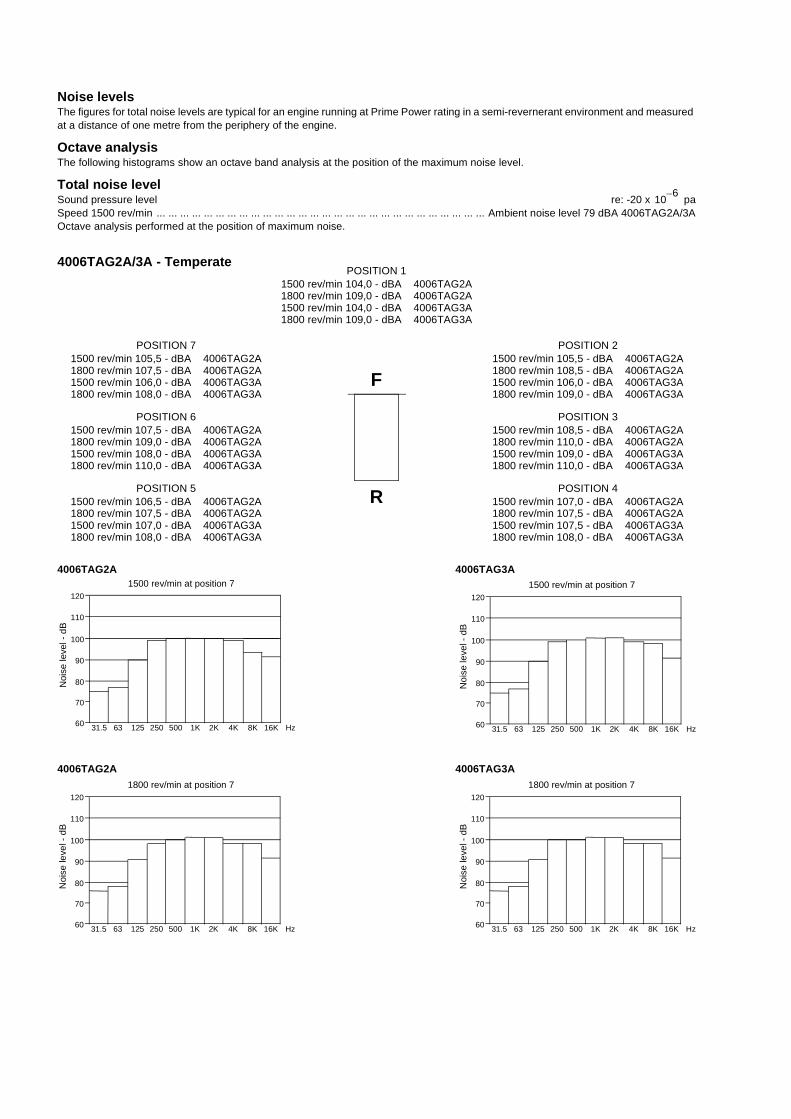
Noise levelsThe figures for total noise levels are typical for an engine running at Prime Power rating in a semi-revernerant environment and measured at a distance of one metre from the periphery of the engine.
Octave analysisThe following histograms show an octave band analysis at the position of the maximum noise level.
Total noise levelSound pressure level re: -20 x paSpeed 1500 rev/min ... ... ... ... ... ... ... ... ... ... ... ... ... ... ... ... ... ... ... ... ... ... ... ... ... ... ... ... Ambient noise level 79 dBA 4006TAG2A/3AOctave analysis performed at the position of maximum noise.
4006TAG2A/3A - Temperate
4006TAG2A 4006TAG3A
4006TAG2A 4006TAG3A
106–
POSITION 71500 rev/min 105,5 - dBA1800 rev/min 107,5 - dBA
4006TAG2A4006TAG2A
POSITION 61500 rev/min 107,5 - dBA1800 rev/min 109,0 - dBA
4006TAG2A4006TAG2A
POSITION 51500 rev/min 106,5 - dBA1800 rev/min 107,5 - dBA
4006TAG2A4006TAG2A
POSITION 21500 rev/min 105,5 - dBA1800 rev/min 108,5 - dBA
4006TAG2A4006TAG2A
POSITION 31500 rev/min 108,5 - dBA1800 rev/min 110,0 - dBA
4006TAG2A4006TAG2A
POSITION 41500 rev/min 107,0 - dBA1800 rev/min 107,5 - dBA
4006TAG2A4006TAG2A
F
R
120
110
100
90
80
70
60 31.5 63 125 250 500 1K 2K 4K 8K 16K Hz
1500 rev/min at position 7
120
110
100
90
80
70
60 31.5 63 125 250 500 1K 2K 4K 8K 16K Hz
1500 rev/min at position 7
Noi
se le
vel -
dB
Noi
se le
vel -
dB
1500 rev/min 106,0 - dBA1800 rev/min 108,0 - dBA
4006TAG3A4006TAG3A
4006TAG3A4006TAG3A
1500 rev/min 108,0 - dBA1800 rev/min 110,0 - dBA
4006TAG3A4006TAG3A
1500 rev/min 107,0 - dBA1800 rev/min 108,0 - dBA
1500 rev/min 106,0 - dBA1800 rev/min 109,0 - dBA
1500 rev/min 109,0 - dBA1800 rev/min 110,0 - dBA
1500 rev/min 107,5 - dBA1800 rev/min 108,0 - dBA
4006TAG3A4006TAG3A
4006TAG3A4006TAG3A
4006TAG3A4006TAG3A
POSITION 11500 rev/min 104,0 - dBA1800 rev/min 109,0 - dBA
4006TAG2A4006TAG2A
1500 rev/min 104,0 - dBA1800 rev/min 109,0 - dBA
4006TAG3A4006TAG3A
120
110
100
90
80
70
60 31.5 63 125 250 500 1K 2K 4K 8K 16K Hz
1800 rev/min at position 7
Noi
se le
vel -
dB
120
110
100
90
80
70
60 31.5 63 125 250 500 1K 2K 4K 8K 16K Hz
1800 rev/min at position 7
Noi
se le
vel -
dB
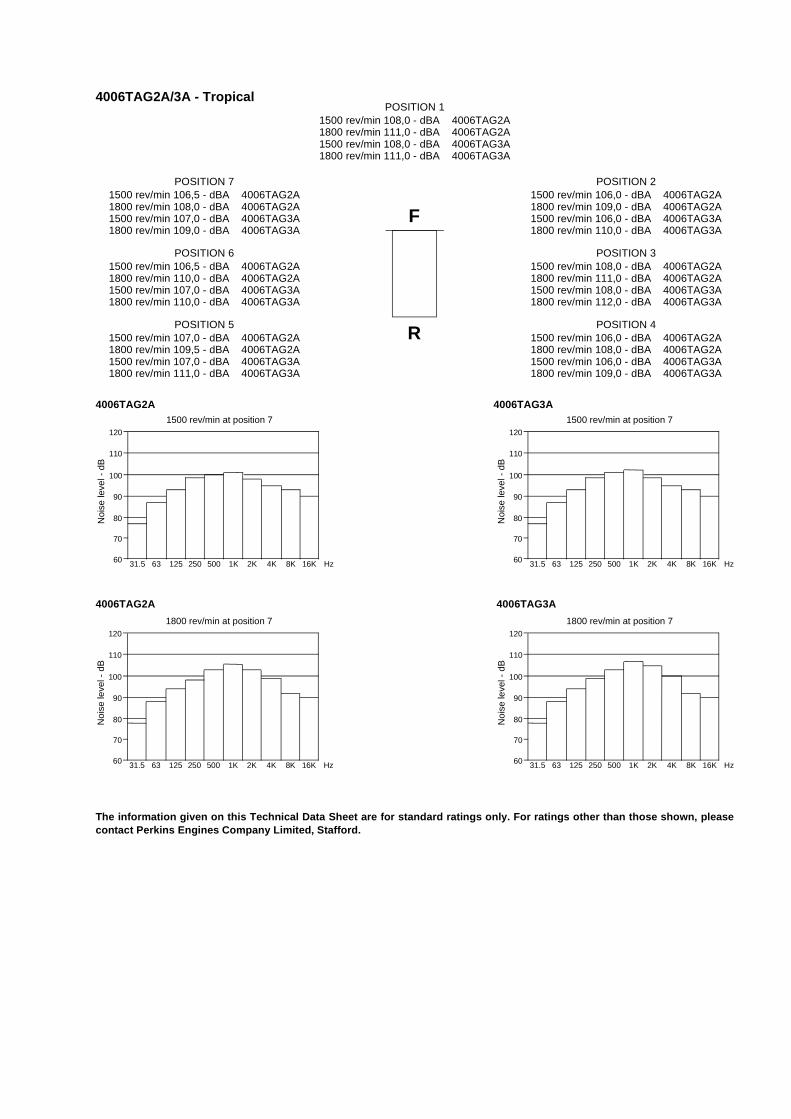
4006TAG2A/3A - Tropical
4006TAG2A 4006TAG3A
4006TAG2A 4006TAG3A
The information given on this Technical Data Sheet are for standard ratings only. For ratings other than those shown, pleasecontact Perkins Engines Company Limited, Stafford.
POSITION 71500 rev/min 106,5 - dBA1800 rev/min 108,0 - dBA
4006TAG2A4006TAG2A
POSITION 61500 rev/min 106,5 - dBA1800 rev/min 110,0 - dBA
4006TAG2A4006TAG2A
POSITION 51500 rev/min 107,0 - dBA1800 rev/min 109,5 - dBA
4006TAG2A4006TAG2A
POSITION 21500 rev/min 106,0 - dBA1800 rev/min 109,0 - dBA
4006TAG2A4006TAG2A
POSITION 31500 rev/min 108,0 - dBA1800 rev/min 111,0 - dBA
4006TAG2A4006TAG2A
POSITION 41500 rev/min 106,0 - dBA1800 rev/min 108,0 - dBA
4006TAG2A4006TAG2A
F
R
120
110
100
90
80
70
60 31.5 63 125 250 500 1K 2K 4K 8K 16K Hz
1500 rev/min at position 7
Noi
se le
vel -
dB
1500 rev/min 107,0 - dBA1800 rev/min 109,0 - dBA
4006TAG3A4006TAG3A
4006TAG3A4006TAG3A
1500 rev/min 107,0 - dBA1800 rev/min 110,0 - dBA
4006TAG3A4006TAG3A
1500 rev/min 107,0 - dBA1800 rev/min 111,0 - dBA
1500 rev/min 106,0 - dBA1800 rev/min 110,0 - dBA
1500 rev/min 108,0 - dBA1800 rev/min 112,0 - dBA
1500 rev/min 106,0 - dBA1800 rev/min 109,0 - dBA
4006TAG3A4006TAG3A
4006TAG3A4006TAG3A
4006TAG3A4006TAG3A
POSITION 11500 rev/min 108,0 - dBA1800 rev/min 111,0 - dBA
4006TAG2A4006TAG2A
1500 rev/min 108,0 - dBA1800 rev/min 111,0 - dBA
4006TAG3A4006TAG3A
120
110
100
90
80
70
60 31.5 63 125 250 500 1K 2K 4K 8K 16K Hz
1800 rev/min at position 7
Noi
se le
vel -
dB
120
110
100
90
80
70
60 31.5 63 125 250 500 1K 2K 4K 8K 16K Hz
1500 rev/min at position 7
Noi
se le
vel -
dB
120
110
100
90
80
70
60 31.5 63 125 250 500 1K 2K 4K 8K 16K Hz
1800 rev/min at position 7
Noi
se le
vel -
dB
All information in the document is substantially correct at the time of printing but may be subsequently altered by the company.
Distributed by
4000 Series 4006-23TAG2A4006-23TAG3A
@Perkins®
Pub
licat
ion
No.
TP
D15
12E
, Iss
ue 3
. Per
kins
Con
fiden
tial:
GR
EE
N. ©
Per
kins
Eng
ines
Com
pany
Lim
ited.
Perkins Engines Company LimitedPeterborough PE1 5NA United KingdomTelephone +44 (0) 1733 583000Fax +44 (0) 1733 582240www.perkins.com
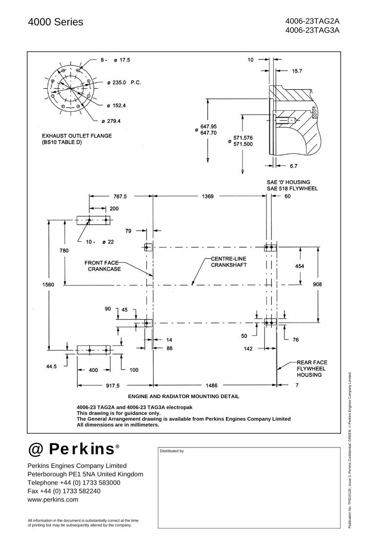
ENGINE AND RADIATOR MOUNTING DETAIL
4006-23 TAG2A and 4006-23 TAG3A electropakThis drawing is for guidance only.The General Arrangement drawing is available from Perkins Engines Company LimitedAll dimensions are in millimeters.
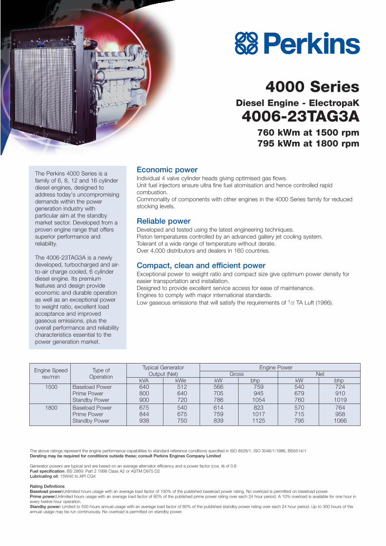
4000 SeriesDiesel Engine - ElectropaK
4006-23TAG3A760 kWm at 1500 rpm795 kWm at 1800 rpm
The Perkins 4000 Series is afamily of 6, 8, 12 and 16 cylinderdiesel engines, designed toaddress today's uncompromisingdemands within the powergeneration industry withparticular aim at the standbymarket sector. Developed from aproven engine range that offerssuperior performance andreliability.
The 4006-23TAG3A is a newlydeveloped, turbocharged and air-to-air charge cooled, 6 cylinderdiesel engine. Its premiumfeatures and design provideeconomic and durable operationas well as an exceptional powerto weight ratio, excellent loadacceptance and improvedgaseous emissions, plus theoverall performance and reliabilitycharacteristics essential to thepower generation market.
Economic powerIndividual 4 valve cylinder heads giving optimised gas flows.Unit fuel injectors ensure ultra fine fuel atomisation and hence controlled rapidcombustion.Commonality of components with other engines in the 4000 Series family for reducedstocking levels.
Reliable powerDeveloped and tested using the latest engineering techniques.Piston temperatures controlled by an advanced gallery jet cooling system.Tolerant of a wide range of temperature without derate.Over 4,000 distributors and dealers in 160 countries.
Compact, clean and efficient powerExceptional power to weight ratio and compact size give optimum power density foreasier transportation and installation.Designed to provide excellent service access for ease of maintenance.Engines to comply with major international standards.Low gaseous emissions that will satisfy the requirements of 1/2 TA Luft (1986).
Typical Generator Engine PowerOutput (Net) Gross Net
kVA kWe kW bhp kW bhp1500 Baseload Power 640 512 566 759 540 724
Prime Power 800 640 705 945 679 910Standby Power 900 720 786 1054 760 1019
1800 Baseload Power 675 540 614 823 570 764Prime Power 844 675 759 1017 715 958Standby Power 938 750 839 1125 795 1066
The above ratings represent the engine performance capabilities to standard reference conditions specified in ISO 8528/1, ISO 3046/1:1986, BS5514/1Derating may be required for conditions outside these; consult Perkins Engines Company Limited
Generator powers are typical and are based on an average alternator efficiency and a power factor (cos. θ) of 0.8Fuel specification: BS 2869: Part 2 1998 Class A2 or ASTM D975 D2Lubricating oil: 15W40 to API CG4
Rating DefinitionsBaseload power:Unlimited hours usage with an average load factor of 100% of the published baseload power rating. No overload is permitted on baseload power.Prime power:Unlimited hours usage with an average load factor of 80% of the published prime power rating over each 24 hour period. A 10% overload is available for one hour inevery twelve hour operation.Standby power: Limited to 500 hours annual usage with an average load factor of 80% of the published standby power rating over each 24 hour period. Up to 300 hours of theannual usage may be run continuously. No overload is permitted on standby power.
Type ofOperation
Engine Speedrev/min
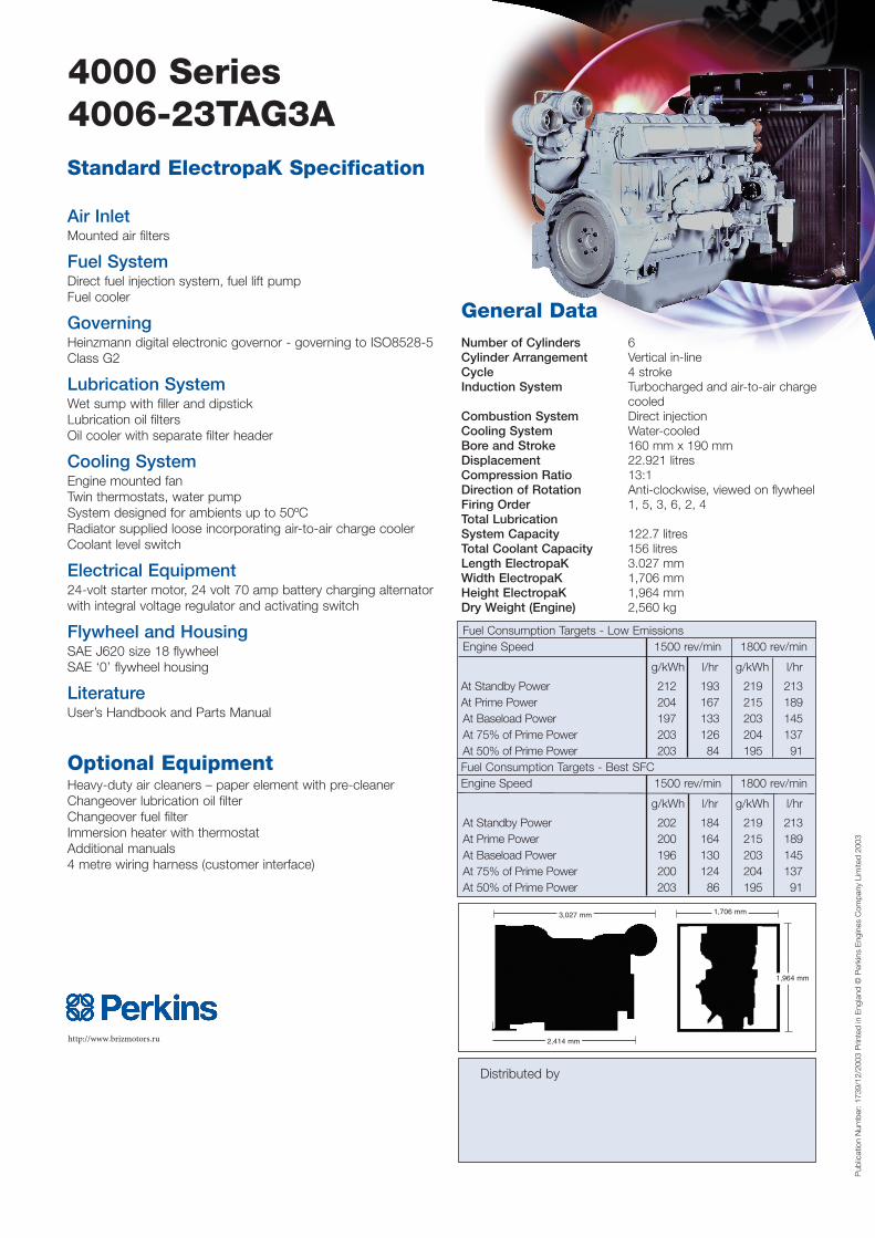
4000 Series4006-23TAG3AStandard ElectropaK Specification
Air InletMounted air filters
Fuel SystemDirect fuel injection system, fuel lift pumpFuel cooler
GoverningHeinzmann digital electronic governor - governing to ISO8528-5Class G2
Lubrication SystemWet sump with filler and dipstickLubrication oil filtersOil cooler with separate filter header
Cooling SystemEngine mounted fanTwin thermostats, water pumpSystem designed for ambients up to 50ºCRadiator supplied loose incorporating air-to-air charge coolerCoolant level switch
Electrical Equipment24-volt starter motor, 24 volt 70 amp battery charging alternatorwith integral voltage regulator and activating switch
Flywheel and HousingSAE J620 size 18 flywheel SAE ‘0’ flywheel housing
LiteratureUser’s Handbook and Parts Manual
Optional EquipmentHeavy-duty air cleaners – paper element with pre-cleanerChangeover lubrication oil filterChangeover fuel filterImmersion heater with thermostatAdditional manuals4 metre wiring harness (customer interface)
http://www.brizmotors.ru
General DataNumber of Cylinders 6Cylinder Arrangement Vertical in-lineCycle 4 strokeInduction System Turbocharged and air-to-air charge
cooledCombustion System Direct injectionCooling System Water-cooledBore and Stroke 160 mm x 190 mmDisplacement 22.921 litresCompression Ratio 13:1Direction of Rotation Anti-clockwise, viewed on flywheelFiring Order 1, 5, 3, 6, 2, 4Total Lubrication System Capacity 122.7 litresTotal Coolant Capacity 156 litresLength ElectropaK 3.027 mmWidth ElectropaK 1,706 mmHeight ElectropaK 1,964 mmDry Weight (Engine) 2,560 kg
Pub
licat
ion
Num
ber:
173
9/12
/200
3 P
rinte
d in
Eng
land
© P
erki
ns E
ngin
es C
ompa
ny L
imite
d 20
03
Distributed by
Fuel Consumption Targets - Low EmissionsEngine Speed 1500 rev/min 1800 rev/min
g/kWh l/hr g/kWh l/hr
At Standby Power 212 193 219 213At Prime Power 204 167 215 189At Baseload Power 197 133 203 145At 75% of Prime Power 203 126 204 137At 50% of Prime Power 203 84 195 91Fuel Consumption Targets - Best SFCEngine Speed 1500 rev/min 1800 rev/min
g/kWh l/hr g/kWh l/hr
At Standby Power 202 184 219 213At Prime Power 200 164 215 189At Baseload Power 196 130 203 145At 75% of Prime Power 200 124 204 137At 50% of Prime Power 203 86 195 91
1,706 mm
1,964 mm
2,414 mm
3,027 mm