Embed Size (px)
Citation preview

Inside this issue:Inside this issue:Inside this issue: “Scandinavian Know-How”
Opel Distributor & Manifold Notes Opel 2.4L Single Side Draft Installation
Volume 32, Issue 4 July/August 2012
Tuning from the Old School
“Peripherals & Performance”

Welcome to the Opel Motorsport Club THE OPEL MOTORSPORT CLUB IS CELEBRATING ITS 32ND YEAR OF DEDICATION TO THE PRESERVATION AND APPRECIATION OF ALL GERMAN OPELS, WITH SPECIAL EMPHASIS ON MODELS IMPORTED INTO THE UNITED STATES. WE ARE HEADQUARTERED IN THE LOS ANGELES AREA, AND HAVE CHAPTERS ACROSS THE COUNTRY, IN EUROPE AND IN CANADA. MEMBERSHIP BENEFITS INCLUDE SUBSCRIPTION TO OUR NEWSLETTER, THE BLITZ, LISTINGS FOR PARTS AND SERVICE SUPPLIERS, BLITZ INDEX AND TECH TIP INDEX (1985-DATE), FREE CLASSIFIED ADS (3 PER YEAR), CLUB ITEMS, OWNER SUPPORT AND ACTIVITIES, INCLUDING MEETINGS AND OUR ANNUAL PICNIC AND CAR SHOW.
ON THE COVER: “Old School” Steinmetz
Side-Draft Carburetor Kit
ADVERTISING IN THE BLITZ CLASSIFIEDS (CARS & PARTS FOR SALE OR WANTED): Up to 50 words, plus name & phone, and a single photo: 1 Month $6.00 3 Months $15.00 6 Months $23.00 12 Months $39.00
(3 Free Ads per year for members)
BUSINESS ADS: (SUBJECT TO CHANGE) Half Page $35 for 1 month, Full Page (Temporarily Unavailable) Insert $120 for 1 month, Business Card $60 for 1year Color Back Cover (Temporarily Unavailable) Send Ad Copy and payment (payable to Opel Motorsport Club) to Blitz Editor.
CHANGE OF ADDRESS:: To minimize delays, please provide the OMC Treasurer with address changes at least one month in advance.
OMC is on the Internet. The site features Club News, Event Coverage, Tech Tips, OMC & Opel History, features and much more.
Visit us at: www.opelclub.com
Other Good Opel Sites: www.opelgt.com Website of the NEOC Includes a Tech help Bulletin Board
[email protected] Subscribe to this useful e-mail posting site
http://clubs.hemmings.com/frameset.cfm?club=oana The OANA Website
The Club The Blitz Regional Chapters
Online Opel Sites
TO APPLY FOR MEMBERSHIP CONTACT: OMC TREASURER, c/o Dick Counsil 3824 Franklin Street La Crescenta, CA 91214-1607
MEMBERSHIP DUES: Regular: $45 Annually via Checks and Money Orders (US funds only, made payable to Opel Motorsport Club) or $47 annually via PayPal.
Online: $20 annually or $21 via PayPal
Send PayPal funds to:
[email protected] Include your name and address information.
MEETINGS: The OMC meetings are as announced, at varying locations. Please consult the OMC Blitz calendar or OMC website to find out who is hosting the next meeting or event.
2012 OPEL MOTORSPORT CLUB FFICERS & STAFF
PRESIDENT TBA VICE PRESIDENT MATT NEWMAN ACTIVITIES TBA TREASURER DICK COUNSIL 818-248-5504 BLITZ EDITOR TBA WEBMASTER RICHARD KAVADAS
SEND EVENT INFORMATION, TECH TIPS, PARTS INFORMATION, LETTERS, CHAPTER ACTIVITY ANNOUNCEMENTS, ADVERTISEMENTS AND ALL OTHER ITEMS OF INTEREST TO:
Opel BLITZ Editor P.O Box 4004 Sonora, CA 95370-4004 USA
Deadline: (At Discretion of OMC Editor)
Submissions will be accepted either typewritten, on Microsoft Word, Publisher or Works compatible disk or e-mailed to the Editor.
Drawings or Photos accepted and encouraged. Contributions to the Blitz will be published on a space-available basis.
The Blitz is the official publication of the Opel Motorsport Club (OMC). Published bi-monthly. Circulation is limited to club members and prospective club members. All submissions become the property of the OMC and will not be returned. Articles, photographs, drawings, technical tips, and other materials appearing in the Blitz may not be reproduced without the expressed, written permission of the OMC. Views expressed are not necessarily those of the officers or members of the OMC.
European Chapter (Netherlands) Contact Louis van Steen: (011 31) 297 340 536 (please take note of the time zone before calling), fast60gt (at) yahoo.com
Florida Chapter (Coral Gables, FL) Contact John Malone: 305-443-8513
Michigan Chapter Contact John Brooks: 616-233-9050 ext 12 Johncinquo (at) hotmail.com.
Mid Atlantic Opel Club (Richmond, VA) Contact Charles Goin: 804-379-9737 cgoin (at) mindspring.com
New England Opel Club (Swansea, MA) Contact Gary Farias: 508-679-2740 Gary (at) opelgt.com
North American Opel GT Chapter (Chicago, IL)
Northern California Chapter (Sonora, CA) Contact Gil Wesson: 209-928-1110 Opelgts (at) opelgtsource.com
Ohio Chapter (Columbus, OH) Contact Larry Shal: 614-861-1565
Pacific Northwest Chapter (Shelton, WA) Contact Paul Kaman: 360-426-9267
Rocky Mountain Opels (Security, CO) Contact Branston DiBrell Jr 719-391-9421 dibrellb (at) rmi.net
Southern California Chapter (Rialto, CA) Contact Todd Martin: 909-355-6735
Texas Opel Club (Leonard, TX) Contact Rodney Killingsworth, 903-587-9640 Tyrodk (at) fanninelectric.com
Carolina Opel Club Contact Roy Bell: 704-782-1866 E-mail: CarolinaOpelClub (at) aol.com We chose to use (at) in place of @ for spam
CLUB OFFICER’S E-MAIL ADDRESS

The theme of this issue was inspired by articles which originally appeared in year 1990 OMC Blitzes, which by themselves weren’t entirely suitable for the next retrospective issue. Another contributory factor was recent accounts of Opel owners being charged large amounts for “performance-built” components (which didn’t perform as promised, as “salesmanship” apparently substituted for methods proven to get results). It seemed a good time to revisit a part of the “roots” of OMC, where the “Motorsport” was prominent enough of a focus to be our club’s “middle name.” So here for OMC club members, we’re examining some of the parts and techniques which can help owners to realize their performance goals on their own.
"How I Beat the 911 Porsche" Dear OMC Folks, “GW” suggested I write - He though you might get a kick out of hearing how the 911 is still laughing. It all started 3 years ago when I first raced my GT. After two years of preparations, the car was ready and I was psyched for my first autocross event. It didn't go very well; the GT's rear end bounced around corners like a hopping rabbit. The 911 driver laughed his head off. A frantic call to my GT parts source and shorter, stiffer springs solved that problem. Next event I thought "I'll show him" and dived into the first corner with greater speed that I'd ever imagined possible. Scared as hell I turned the wheel into the corner but the GT kept on going straight ahead, through the pylons - corner workers scattering. I could see the 911 driver doubled over with laughter at the far end of the course. I'd just experienced the notorious Opel understeer. Another call for trick parts, I bought the biggest sway bar I could find. Next event, 1-inch front bar installed, understeer was even worse! Nobody told me you need a larger rear bar to correct an understeering front engine, rear wheel drive car. And so it went throughout my first year of auto crossing. The GT moved through Stock, Street Prepared, and finally to E prepared class with the installation of pop-top pistons, ported head, and autocross camshaft. Driving skills also improved But the 911 was still laughing. I spent 1989 in retirement, I went to Norway to study Manta and Ascona drivers, race cars, and engine prep. I drove a rally car. I didn't tell anyone that I was a failure on the slalom course. To make this story short, I just got the GT running again, The car was set up with new shocks, springs, and super-duper “W” bushings. A European limited slip, 4.22 final drive and close-ratio 4-speed were installed. And for good measure, a mild race camshaft degreed-in. Last week, the first full race of the season, I beat the 911! I beat him good - by a full second on a 60-second course. Talk about Fahrvergnugen - I felt great. The Opel goes like stink. What a car. Only one problem: I trashed my new engine. Autocrossing has provided the opportunity to objectively evaluate my car and driving performance. When a new part is added it's great to be able to measure the effect and to recognize improving driver skills. Incidentally, the 911 is evolving too. It now runs in B Street Prepared class and the driver is in his 4th year of auto crossing. When the Opel and I finally solve this engine reliability problem and get the suspension sorted out, we'll write a detailed article on the secrets of killer GT prep for slalom competition. I'm counting on you “G”.
Carl Goodpasture’s Racer Opel GT
GT consumes yet another product from
Dr. Ferdinand Porsche (Image by Blaine Scheidt)
www.opelclub.com 07/12

“Old School” Opel Tuning Why Old School??
In times of uncertainty, a sense of nostalgia carries appeal. And many are feeling today, that when it comes to the enjoyment of tuning a daily-driver car yourself, something has been lost.
The original Opel speedshops made use of components and techniques that were derived of all-mechanical means - As opposed to the electronic-based approaches of recent times.
Back in the day within the US, the most notable efforts were those of the original aftermarket Opel supplier, “More Opel” of Seattle. Arising from a demand for competition parts which were not being supplied over the counter by Buick dealers, they became the sole US distributor for Opel tuning solutions then produced in Europe by “Steinmetz Automobiltechnik.”
Fortunately many of these same Steinmetz products were imaged, and results of their performance improvements were graphed (along with Irmscher) in old German-language books compiled for Opel enthusiasts. These are seen here, next to the More Opel catalog page which described them in 1972.
Much of what they sold is no longer practicable!
Installation of exceptionally high-profile camshafts, high-dome piston designs, and 194HP-capable heads are no longer workable or desirable with today’s downgraded ethanol-fuel blends and in today’s traffic-choked road systems. However, some alternative approaches proven streetable, are covered here in this issue.
Similarly, while many of the original high-performance builders for the Opel no longer offer parts for the classic CIH engines, a handful of small-batch producers have reintroduced suitable replacement parts which offer much the same functions— and just a bit of boost greatly benefits the Opel’s power/weight ratios.
So this article details one of the overlooked aspects of getting the most “joy” out of that 40-year-old Opel you’re driving: Knowledge and applications of selected engine “peripherals” which can still be bolted-on for extra street-worthy performance.
www.opelclub.com 07/12
Maximum Potentials
Common Upgrades

"Tuning Opel's Cast Iron Engine: Scandinavian Know-How" Reprint of 1990 article by Carl Goodpasture Affectionately called "jarnmotor" in Sweden, Opel's cam-in-head (CIH) engine has for 20 years powered the Kadet, Manta, and Ascona to hundreds of victories over thousands of road rally miles across Norway, Sweden, and Finland. Especially the Swedes have taken the development of the CIH engine to its maximum potential. Sadly, however even in Europe where Opels are as common as are Chevy's in the States, the CIH engine is rapidly becoming obsolete. Indeed, two years ago, with the lapse of the "five year rule," the jarnmotor cars were dropped from group A eligibility and international competitiveness. CIH race cars survive today only at local events in National Class rally and rally cross-competition. Clearly this engine in race tune as well as trick parts for performance modification will soon pass out of existence as has happened to classic Opel enthusiasts in the States. The purpose of this article is to share some of the tuning secrets observed during recent visits with various Norwegian and Swedish engine builders. The following information on stages of tune for the CIH engine were provided by Jan Carneborn of ENEM, a well-known engine builder and parts supplier in Stockholm. Mr. Carneborn's firm has done a tremendous amount of research and development work on the CIH engine including some of the early tuning for GM Motorsport. Their attentions are currently turned toward developing the 16-valve Corsica for group A competition. The HP vs. RPM graphs for the various levels of modification described are taken from an ENEM catalog of 1982/1983. It should be mentioned that the ENEM catalogs are a rich source of information for anyone considering an Opel engine build-up. If you can get hold of a catalog and can read Swedish, the effort is well rewarded. Many of the engine parts described and illustrated in the ENEM catalogs may be available from other sources in Europe such as Irmscher in Germany. However, many of the most intriguing parts are rapidly becoming unavailable as stocks are not being replenished as the engine fades from popularity. Examples include close ratio gear sets, 5.26:1 final drive gears, and the big-port "Group 1" head casting. My apologies to Mr. Carneborn for any errors in translation. Material not in quotation represents my own interpretation of information gleaned from shop talk with race drivers and their mechanics in dimly-lit Norwegian garages and in the pits on race days.
"Daily we receive requests like how do we get 120hp,
150hp, etc.,, from the CIH Opel engine."
The accompanying power curves and descriptions of the various engines tested will answer these questions.
Referring to the diagram, the curves show the effects of different combinations of equipment.
The curves are taken from engines we have tuned
in our shop and run on our Borg & Saveri dynamometer which can measure up to 400hp
via digital readouts.
All data are based in 2-liter CIH engines with cast iron non-crossflow heads and
breaker-point Bosch transistorized ignition systems.
www.opelclub.com 07/12

"Curve no. 1" represents the hottest group 2 engine with 48mm Weber carbs, ENEM intake manifold, maximally ported 'group 1' head with polished 45mm intake - 40mm exhaust valves (see Table 1 for a listing of valve sizes used in CIH race engines), H12 camshaft (table 2 gives cam grind specifications), polished high-compression dome-topped pistons, transistorized ignition, and Rally exhaust system (essentially a stock type 4-into-1 cast header with 2 1/2 inch exhaust pipes). Results greater than 200hp have been obtained with other engines, The broken curve shows the effect of running the same engine with a 2-into-1 design tube header. ENEM has spent hundreds of hours developing a better-than-stock header referred to as a "Roret" header. This is a 2-into-1 design with primary pipes of 2-inch diameter, 24 inches ling. 2 1/1 inch secondary pipes dump into a 3 inch collector. It is (was) not group A legal, develops 11 more horsepower at 4,000 rpm's and 7 more horsepower at 7,000 rpm's. Engine revs faster especially at the lower end. "Curve no. 2" is an Ascona 2000i engine tuned to group A regulations as defined by the international sanctioning body, FIA, which dictates European race rules The difference between group A and group 2 is that in group A the carbonation differs as follows: 2 Solex 45 DCOE's with 36mm venturi instead of 48mm Webers, valve diameters limited to 42.15 and 37mm, cam grind P2. In addition the flywheel weight must be within specifications provided by the manufacturer (e.g. listed in the car's homologation papers). Otherwise the engine is as in group 2 (group 2 engines can run a lightened flywheel). "Curve no. 3" shows a Kadet 2.0E (injection) engine tuned to group A regulations. The effect of reduced airflow due to throttle body metering is shown. The injection engine, on the other hand, runs smoother with a wide power band. "Curve no. 4" shows an Ascona 2.0i engine with 2 45mm Solex carbs, I3 or E11 camshaft, 42/37mm valves, and original flat top pistons, We recommend no higher state of tune using stock pistons as ring lands and piston pin area may break. Higher compression and greater valve timing overlap are limited using stock pistons. Relieving the pistons for greater valve clearance will lower compression so that the head must be planed and the valves relieved even deeper. The solution is high compression dome-topped pistons with valve reliefs. "Curve no. 5" shows an engine equipped with Weber 36/36 carburetor, street type I10 cam, head with 42/37mm valves, head planed 1mm which increases compression about one point, and rally exhaust system. Beware that these modifica-tions are not street-legal as the engine will not meet emissions standards. these modifications are for race use only. Note on the ignition system used on these engines: A Bosch breaker point type distributor with vacuum advance not connected is used on most tuned Opel engines. The Bosch part number stamped on the body of the distributor is 0231170147. The GM part number is 09286542. The distributor advance weights are adjusted for total advance at 4,000 rpms. Group 2 engines with high compression pistons use 36-37 degrees total advance. Moderately tuned engines with planed head and original pistons use 33-34 degrees total advance. Injection engines, moderately tuned with planed head and original pistons use 32 degrees total advance. A Bosch coil and transistorized multiple spark system (Bosch part no, 0227100901 as used by Ford, Opel Saab, and Volvo) is used. Spark plugs used on group A and group 2 engines are NGK and Bosch Platinum. Note on engine blocks used in Scandinavian race cars: The 1.9 with both carbureted and fuel injection version was the only CIH 4-cylinder engine imported into the USA. The 1.9 block is virtually identical to its larger bore cousins except that the 1.9 casting has a somewhat thinner cylinder wall. Thus, the 1.9 block is frequently bored to 95mm tuned to develop about 150 horsepower. The 2 liter block, in contrast, can be bored to 97mm. The 2 liter block is preferred for a tuned engine developing more than 150 horsepower. High compression done-topped pistons are (were) available for cylinder bore diameters of 95.05, 95.30 and 95.50mm from Mahle (ed note: these have since been discontinued) the German piston manufacturer. Using Mahle pistons in a 2 liter engine, a compression ratio of about 11.4:1 is obtained without planing the head. The 2 liter blocks available in Europe are those of the 2.0N engine with 8:1 compression, the 2.0S with 9:1 and the 2.0E with 9.4:1 compression, These three engines were used in fuel-injected Asconas, Mantas and Rekords. The 2.0i was an Ascona engine with a compression ratio of 9:1 and 2 Solex side draft carburetors. The two long stroke engines, the 2.2i and 2.4 were Bosch Jetronic equipped high-compression engines, The 2.4 was most unusual in its alloy crossflow dual overhead camshaft, 16 valve form which produced 144 horsepower at 5,200 rpms in stock form. www.opelclub.com 07/12

The take-home lesson for the American engine builder would be to investigate the availability of performance parts from overseas. To this end, I have appended a list of three English-speaking Scandinavian part suppliers:
All former rally drivers and all well-equipped with a powerful dose of Viking twinkle in their eyes.
(Editor’s note: The data referenced is now 22 or more years out of date, and therefore some potentially-obsolete manufacturer names and some mailing addresses are not reprinted here.
The part sellers in 1990 were given as Jan Carneborn of www.enem.se, Jan Karlsson of Jaka Racing, and Erik Waldenstrom of Din Rally-boutique , and anyone wishing to try to locate their current whereabouts
are referred to Swedish Internet Search Websites).
www.opelclub.com 07/12

"Lightened Flywheel for the 1.9 Engine" Opel performance enthusiasts seeking better engine response may be interested in the idea of using a lightened flywheel. First of all be assured that a significantly lighter than stock flywheel does produce a crisper, faster-revving engine. Just ask Roger Lee or any well-initiated "prepared" or "modified" category auto-crosser. Even "street prepared" or "improved touring" race engine preparation routinely includes machining the flywheel down to minimum manufacturers' specifications to save weight and get that last ounce of "acceleration out of the corners." The purpose of this note is to suggest how one might obtain a lightened flywheel and comment on its cost. An aluminum flywheel can be purchased from a company willing to make one up to your specifications, such as PAECO of Birmingham, Alabama (offering 6 lb. and 8 lb. "streetable" versions at a $450 base price - but don't forget you'll also need a ring gear and its installation on the flywheel, plus shipping). Alternatively, following the suggestion of Jurgen Wolters writing in the "GT Journal" (magazine) of January 1989, a machine shop with an engine lathe can turn a flywheel down to nearly one-half of its stock weight of 23 lbs. Bob Childers of Childers Machine Shop in Albuquerque recently machined two original used flywheels, one from 23 lbs. to 15 lbs. and the over from 22 lbs. to 13 lbs. according to the dimensions given in the diagram below. The job required 5 hours of careful work and cost $180. This cost included removing the ring gear and reinstalling it in reverse to expose new and unworn teeth to the starter drive gear. If the final cut is made with a fine tool or with a stone, a smooth machined surface free of chatter marks which might act as stress risers will result. It should be noted that some feel that a machine-lightened flywheel is dangerous citing examples of disintegration on over-revved race engines (it's usually the clutch rather than the flywheel that usually lets go). It might be preferable to machine a lighter-than-stock flywheel from billet steel rather than use the original Opel cast-iron wheel.
PAECO Catalog (1990 cover)
GT Journal January 1989 cover
One of 90 issues published in Germany (from 1986-1994) as
edited by Albert Heinel
www.opelclub.com 07/12

Ignition Tuning Notes Adapted from comments by Bob Legere
The vacuum advance unit can be retained on mild applications to retain good throttle response and fuel economy, with only minimal modifications. Around five degrees of initial timing can be used for better throttle response on this type of application - more could be used depending on the gasoline octane used, but the total timing is a limiting factor.
The distributor itself may have to be modified for better performance if a more radical cam is used than stock. To help quicken mid-range response, a lighter secondary spring in the distributor's mechanical advance will accelerate the advance curve. If a hotter cam is used however (280 degrees of duration or more), there may not be sufficient vacuum to operate the vacuum advance properly, plus this type of cam tends to like more initial timing (say 8-12 degrees) to respond well. This will usually make the engine ping due to excessive advance (initial advance, plus vacuum advance plus mechanical advance).
In a case such as this, a standard distributor can be converted to use as a full mechanical advance. The vacuum advance canister can be removed or retained, it really doesn't matter (I think they look better removed), and the upper breaker plate can be pinned, riveted, welded, or whatever to the lower breaker plate. This will prevent timing fluctuations due to the plates rotating back and forth. Then the timing advance curve (the rpm at which full advance is accomplished and how soon it starts to advance) can be altered by playing with the spring tensions, altering the centrifugal weights (lighter weights will make the advance come in later, heavier weights will come in sooner), or changing the travel of the weights to increase or limit the total mechanical advance. The simplest way is to just substitute the heavier "secondary" spring with one similar to the lighter "primary" spring. This will have the advance come in a bit sooner than stock, and with 8 degrees if initial advance, usually leave you with 34 degrees of total advance (this will vary with different year distributors). Lower compression engines will tolerate more timing than this but the true limit is the detonation threshold and the ease of starting, as too much initial timing will tend to make a vehicle slow to crank over, as if the battery were dying.
Illustration characterizes relative functions of the different springs
which regulate mechanical advance
Mechanical Advance (Explained)
The mechanical advance control consists of the movement of the cam by the two governor weights. One weight is controlled by a weak spring and the other is controlled by a strong spring.
The weak spring lets the advance start at relatively slow engine speeds, but is strong enough to keep the timing from advancing at idle speed. As engine speed increases, the centrifugal force developed by the other
governor weight overcomes the tension of the strong spring, so it starts to move out from its normal position.
This movement of the weights rotates the cam on the distributor shaft. As the cam moves forward in relation to the shaft rotation, the lobes of the cam meet the rubbing block (or the electronic ignition module, if equipped) on the contact arm sooner.
This makes the spark occur at the plug sooner, in relation to piston travel. So, the spark occurs at varying times, either before or after the piston reaches top dead center position, depending upon the requirements of that particular engine.
Vacuum Advance (Explained)
The vacuum advance control consists of the movement of the breaker plate by a diaphragm and connecting arm which operate according to the amount of vacuum present in the carburetor. The vacuum unit is mounted to the distributor,
and is connected by a tube to the carburetor, above the throttle valve.
Engine vacuum, developed in the cylinder and intake manifold by the intake stroke of the piston, is prevented from reaching the connection at idle speed because the throttle valve is closed. When the throttle valve is opened, air rushes
by and creates a vacuum at the tube connection, which operates the vacuum unit.
The vacuum unit consists of a housing which contains the diaphragm and the connecting arm, and the outer end of the arm is attached to a pin on the moveable breaker plate. The arm draws the
breaker plate around in a direction which makes the rubbing block of the ignition points (or the electronic ignition module, if equipped) meet the lobe on the cam sooner than it would in normal position.
This also advances the timing, since it makes the spark occur sooner at the plug.
So the timing is advanced in two ways First by the governor weights rotating the cam clockwise; Second, by the vacuum unit rotating the breaker plate in the opposite direction. And, since each mechanism operates independently of each other, you need to evaluate
the operation of each mechanism independently (when you service your distributor). Keep in mind that the vacuum unit operates according to the carburetor throttle opening and therefore affects economy…while the
governor weights operate according to engine speed, and therefore affect developed power.
www.opelclub.com 07/12

Distributor Notes Removal of the Opel 1.9 distributor requires unbolting and removal of the mechanical fuel pump (from the lower driver’s side of the timing cover). When a distributor is off the car, the breaker plates can be removed, cleaned and lubricated. Disassembly is as simple as removing the screws which attach the plates to the housing (and detaching the vacuum advance arm). Keep all small hardware in a safe location until reassembly is completed. Other important components can also be checked, like the braided wire which is needed to make a good ground connection between the plates. Check the main shaft for wobbling, and check the internal weights and springs for binding. An important contact point is where the condenser is mounted to the distributor housing, this is an area where you need to clean off any grease and lightly sand the outer housing for contact. To install the Opel 1.9 distributor the engine needs to be rotated to #1TDC (where the timing marks lineup, and where both #1 valves are closed) Then reach into the distributor mounting area with a long flat-blade screwdriver, to rotate the oil pump gear cog to a position approximately 15 to 20 degrees clockwise of the #1TDC mark (which is about 4:30 if the distributor housing were a 12-hour clock). When you set the distributor in place, the rotor will move counter-clockwise that 15 to 20 degrees (because of action of the angled drive gear teeth on the distributor shaft). After installing the distributor correctly, then apply sealer to the fuel pump spacer and re-install the fuel pump.
Distributor Vacuum Diaphragm Evaluation
After years of operation, the vacuum diaphragm in the distributor can develop a hard-to-identify vacuum leak.
You can do a quick test by sucking on one end of the advance hose and observing the breaker plates in the distributor (they should move slightly).
Verifying that the diaphragm will hold vacuum completely, requires a leak-down test with a hand held air pump (of the type shown at right).
If leaking, replace with a newly-rebuilt distributor. The diaphragm’s “arm” moves breaker plates back and forth
Distributor Vacuum Hose Connections Advance Hose: This is the wider hose which connects a port on the passenger side of the carb (facing the passenger side fender), to the wider port on the distributor.
Retard Hose: This hose connects to a thin port from the “booster tree” fitting on the fender-facing side of the intake manifold.
Carburetor Port: Vacuum Advance
Manifold Port: Retard Hose
connects here 1970-1974 type Opel Distributor
Retard
Advance
(1A) Camshaft Dowel Pin at “6 o’clock” bottom and - Flywheel ball mark (1B) lines up with pin
1B
1A
Correct #1TDC
#1 TDC
#1 TDC Mark
Installation Position 15-20 degrees
Rotor
Align gear cog keyway, to install
distributor
www.opelclub.com 07/12

Distributor Applications
One often overlooked contributor to Opel drivetrain performance is proper application and operation of the ignition distributor. This goes beyond just setting the baseline timing and verifying an adequate point gap or dwell. In Technical Service Bulletin #73-I-08, Opel suggested performing a procedure using an “advance timing light,” to verify that the mechanical and vacuum advance mechanisms of the distributor are working within their designed specifications.
Unfortunately, in our observation, no compilation of technical data on the Opel distributors has ever been organized. This is unlike other vehicle makes like Porsche and VW, which included graphs of performance curves in technical books. Some information can be found in the Opel factory service manuals for each model year, along with additional but contradictory information in the Opel part books.
Here we’ve clarified that information based on going through an actual stack of distributors pulled from 1.9L Opels.
1968-1969 Kadett (Bosch 0-231-167-006) (Opel Part #1212026, Installed on both Manual & Auto Trans models) Has 2 separate vacuum canisters, one for advance and one for retard Has flat surface around top edge of housing Total Advance (Centrifugal & Vacuum), Engine degrees at 2500 RPM’s:43-55 Total Advance (Centrifugal & Vacuum), Engine degrees at 3600 RPM’s:51.5-59 Centrifugal Advance, Start Advance at RPMs: 800-1100 Centrifugal Advance, Medium Advance, Degrees at RPMs: 17-23 @ 1500 rpm’s Centrifugal Advance, Maximum Advance, Degrees at RPMs:31-37 @ 3200 rpm’s Vacuum Advance, Start Advance, Engine Degrees and Inches of Vacuum:3-6 Vacuum Advance, Maximum Advance, Engine Degrees and Inches of Vacuum: 18-24 @ 13 in. Vacuum Retard, Engine Degrees at Closed Throttle: -4 to –9 Serial Number Location
1969-1970 GT & 1970 Kadett (Bosch 0-231-167-007) (Opel Part #1212026, Installed on both Manual & Auto Trans models, See Note**) Has 1 combined vacuum canisters, with ports for both advance and for retard Has indentation in surface around top edge of housing Total Advance (Centrifugal & Vacuum), Engine degrees at 2500 RPM’s:43-55 Total Advance (Centrifugal & Vacuum), Engine degrees at 3600 RPM’s:51.5-58.5 Centrifugal Advance, Start Advance at RPMs: 800-1100 Centrifugal Advance, Medium Advance, Degrees at RPMs: 17-23 @ 1500 rpm’s Centrifugal Advance, Maximum Advance, Degrees at RPMs:31-37 @ 3200 rpm’s Vacuum Advance, Start Advance, Engine Degrees and Inches of Vacuum:3-6 Vacuum Advance, Maximum Advance, Engine Degrees and Inches of Vacuum: 18-24 @ 13 in. Vacuum Retard, Engine Degrees at Closed Throttle: -4 to –9
**Note:/Caution: None of the information published for this model distributor can be confirmed as accurate.. The part number that Opel provided directly conflicts with part descriptions of its components. This may be the rarest Opel distributor, with some references indicating it was only installed in vehicles manufactured during July and August 1969. Related references state it was installed up to engine serial number 19S-0362167
Serial Number Location
1968-1969 GT (Bosch 0-231-167-005) (Opel Part #1212026, Installed on both Manual & Auto Trans models) Has 2 separate vacuum canisters, one for advance and one for retard Has flat surface around top edge of housing Total Advance (Centrifugal & Vacuum), Engine degrees at 2500 RPM’s:43-55 Total Advance (Centrifugal & Vacuum), Engine degrees at 3600 RPM’s:51.5-59 Centrifugal Advance, Start Advance at RPMs: 800-1100 Centrifugal Advance, Medium Advance, Degrees at RPMs: 17-23 @ 1500 rpm’s Centrifugal Advance, Maximum Advance, Degrees at RPMs:31-37 @ 3200 rpm’s Vacuum Advance, Start Advance, Engine Degrees and Inches of Vacuum:3-6 Vacuum Advance, Maximum Advance, Engine Degrees and Inches of Vacuum: 18-24 @ 13 in. Vacuum Retard, Engine Degrees at Closed Throttle: -4 to –9 Serial Number Location
1970 GT & 1970 Kadett (Bosch 0-231-167-024) (Opel Part #1212029, Installed on both Manual & Auto Trans models) Related references state it was installed after engine serial number 19S-0362167 Has 1 combined vacuum canister, with ports for both advance and for retard Has indentation in surface around top edge of housing Total Advance (Centrifugal & Vacuum), Engine degrees at 2500 RPM’s:43-55 Total Advance (Centrifugal & Vacuum), Engine degrees at 3600 RPM’s:43.5-50.5 Centrifugal Advance, Start Advance at RPMs: 800-1100 Centrifugal Advance, Medium Advance, Degrees at RPMs: 17-23 @ 1500 rpm’s Centrifugal Advance, Maximum Advance, Degrees at RPMs:31-37 @ 3200 rpm’s Vacuum Advance, Start Advance, Engine Degrees and Inches of Vacuum:3-6 Vacuum Advance, Maximum Advance, Engine Degrees and Inches of Vacuum: 18-24 @ 13 in. Vacuum Retard, Engine Degrees at Closed Throttle: -4 to –9
Serial Number Location Vacuum Arm No “809” www.opelclub.com 07/12

1971-1972 GT, Manta/1900 Series & Kadett (Bosch 0-231-167-037) (Opel Part #1211008, Installed only on models with Manual Transmission) Has 1 combined vacuum canister, with ports for both advance and for retard Has indentation in surface around top edge of housing Total Advance (Centrifugal & Vacuum), Engine degrees at 2500 RPM’s:43-55 Total Advance (Centrifugal & Vacuum), Engine degrees at 3600 RPM’s:35-42 Centrifugal Advance, Start Advance at RPMs: 1100-1200 Centrifugal Advance, Medium Advance, Degrees at RPMs: 7.5-15 @ 1400 rpm’s Centrifugal Advance, Maximum Advance, Degrees at RPMs:28-32 @ 3600 rpm’s Vacuum Advance, Start Advance, Engine Degrees and Inches of Vacuum:-5 degrees @2.9-4.1 Vacuum Advance, Maximum Advance, Engine Degrees and Inches of Vacuum: 7-10 @ 5.6-6.4 in. Vacuum Retard, Engine Degrees at Closed Throttle: -4 to –9
Serial Number Location Vacuum Arm No “845”
1971-1972 GT, Manta/1900 Series & Kadett (Bosch 0-231-167-038) (Opel Part #1211009, Installed only on models with Automatic Transmission) Has 1 combined vacuum canister, with ports for both advance and for retard Has indentation in surface around top edge of housing Total Advance (Centrifugal & Vacuum), Engine degrees at 2500 RPM’s:43-55 Total Advance (Centrifugal & Vacuum), Engine degrees at 3600 RPM’s:35-42 Centrifugal Advance, Start Advance at RPMs: 1100-1200 Centrifugal Advance, Medium Advance, Degrees at RPMs: 7.5-15 @ 1400 rpm’s Centrifugal Advance, Maximum Advance, Degrees at RPMs:28-32 @ 3600 rpm’s Vacuum Advance, Start Advance, Engine Degrees and Inches of Vacuum:-5 degrees @2.9-4.1 Vacuum Advance, Maximum Advance, Engine Degrees and Inches of Vacuum: 7-10 @ 5.6-6.4 in. Vacuum Retard, Engine Degrees at Closed Throttle: -4 to –9
Serial Number Location Vacuum Arm No “847”
1973-1974 GT, Manta/1900 Series (Bosch 0-231-167-012) (Opel Part #1211028, Installed on both Manual & Auto Trans models) Has 1 combined vacuum canister, with ports for both advance and for retard Has indentation in surface around top edge of housing
Total Advance (Centrifugal & Vacuum), Engine degrees at 2500 RPM’s:43-55 Total Advance (Centrifugal & Vacuum), Engine degrees at 3600 RPM’s:29-37 Centrifugal Advance, Start Advance at RPMs: 1000-1200 Centrifugal Advance, Medium Advance, Degrees at RPMs: 7.5-15 @ 1400 rpm’s Centrifugal Advance, Maximum Advance, Degrees at RPMs:28-32 @ 3600 rpm’s Vacuum Advance, Start Advance, Engine Degrees and Inches of Vacuum:-5 degrees @2.9-4.1 Vacuum Advance, Maximum Advance, Engine Degrees and Inches of Vacuum: 1-5 @ 4.5-5.0 in. Vacuum Retard, Engine Degrees at Closed Throttle: -5 **Notes This distributor includes model-specific parts which are unique and are not interchangeable with other distributors. The vacuum canister has screw locations which are vertically offset, and will not bolt onto other models. The distributor housing has a square hole for access to the insulator for the wire of the condensor.
Serial Number Location Vacuum Arm No “921”
1975 Manta/1900 Series (Bosch 0-231-170-140) (Opel Part #9293055, Installed only on models with Automatic Transmission) This is a special distributor with internal mechanical advance, originally installed only in Opels equipped with Bosch LE-Jetronic Fuel Injection Systems. It is identifiable by its unique vacuum canister, with a single port for retard only. Has indentation in surface around top edge of housing This distributor requires a unique point set, with a point gap of .016” Total Advance (Centrifugal), Engine degrees at 3400 RPM’s:21-25 Centrifugal Advance, Start Advance at RPMs: Zero Degrees at 1100-1400 rpm’s Centrifugal Advance, Medium Advance, Degrees at RPMs: 10-14 @ 2000 rpm’s Centrifugal Advance, Maximum Advance, Degrees at RPMs:21-25 @ 3400 rpm’s Vacuum Retard, Engine Degrees at Closed Throttle: 4
Serial Number Location Vacuum Arm No “661”
www.opelclub.com 07/12

Distributor Mechanical-Advance Conversion Based on Comments from Roger Lee Use an original 1971-1974 model-year Opel distributor which was originally installed onto a low-compression Opel engine.** Acquire a good used original Volkswagen "009" distributor via Ebay or from a VW part vendor. From the 009 remove the springs, counterweights and the breaker plate, and lay them aside where they will be secure.** On the Opel distributor, remove the vacuum canister. Disassemble the breaker plate, internal springs and counterweights, and lay all the small attaching part aside where they will be secure. Swap over the "009" springs, counterweight and breaker plate onto the Opel distributor housing. To fill the open side access hole, you can either re-mount the vacuum advance canister (leaving its arm un-connected at the breaker plate) or cover it using a small piece of metal drilled with a small hole located to use one of the distributor mounting screws. Roger advocates also using an electronic ignition kit, or installing a point set from the Porsche 914 (equivalent to Bosch 1-237-013-310, according to an online source) as he considers it to have a higher-tension spring. When setting for tuning, the "009" conversion should have an advance curve that comes in faster than some Opel units. (Tuning notes for the similar "1975 Opel" mechanical advance unit, follow). Final testing and verification can be performed with an advance-timing light or by an old-school distributor tester (as illustrated below) If there is any additional tweaking required, a "VW Speed Shop" might be able to help (a good list is online at: www.dasvolks.com/links/)
VW “009” distributor (note shorter shaft compared to Opel)
Bosch Distributor Advance Curve Graph Example shown is from Porsche application
(as unfortunately none are known to have been published for Opel engines)
**Notes: The 1971-1972 Opel distributors differ from the 1973-1974; We haven’t confirmed which is best for this conversion. The "009" refers to the last 3 digits of the Bosch distributor which came with a centrifugal "mechanical" advance,
which was originally installed in selected early 1970's VW models. An abundance of information about this distributor is available online by searching just the terms "009" and "Volkswagen", including references to a longer serial number "0231178009" also bearing a reference "JF4" and an unconfirmed association to VW part number 126905205.
Although the "009" has been reproduced by EMPI, online discussion boards indicate that these do not provide the same quality of performance as the originals bearing the Bosch "009" markings do.
Advance Timing Light Exploded View
“Old School” Tester
www.opelclub.com 07/12

Installing the 1975 Opel Distributor The 1975 Opel distributor (Bosch #0231170140) is a frequent subject of speculation among Opel tuners, as it is the only model originally constructed with an internal full mechanical advance. Although earlier Opel distributors had a partial mechanical advance, their idle advance was dependent upon delivery of a vacuum - which in some cases can suffer from other high-performance modifications like a choppy higher-lift profile camshaft or from some side-draft manifolds which do not have a readily available provision for a separate manifold vacuum port.
This distributor was originally offered with the 1975 Opel fuel injection system, and has a unique "retard only" vacuum canister, which allows tuners to cap the vacuum advance port on the carburetor. Word was that this distributor provided a smoother acceleration curve as a result of its design, which was enough of a prospect for me to pop for $122 for a rebuilt model that was offered at one time on Ebay.
While it arrived in good condition, complete with a cap and ready to bolt-on, there were some adaptations required to actually make it workable. The 1975 employs a breaker plate with a reversed orientation for a set of breaker points, when compared to other Opel models. As this was to be used with an electronic ignition module sourced from another Opel distributor, it took some time to determine how to lay the 2 wires connecting the module across the breaker plate (and out of the way of the spinning center distributor shaft). To secure the wires, the "insulator" was moved down the wires a bit.
First Installation Attempt. The distributor was installed so it was close to being "static-timed" at about zero degrees TDC (top dead center"), which is where other Opel distributors are set. Using a plastic feeler gauge, the electronic ignition module was adjusted to where a dwell reading at a rock-steady 50 degrees (= 25 degrees on a 8-cylinder meter) was achieved. Then the vacuum advance port on the carburetor was capped and a hose to the vacuum retard port was hooked up. The result was an engine that would barely idle at a low speed.
Second Installation Attempt: The idle tuning was advanced, and adjusted "by ear" until the engine ran at a steady higher idle. This seemed fine, until the initial road test revealed it ran flat and severely bogged at about 2200 rpms and didn't accelerate smoothly until 3000 or more rpms.
Third Installation Attempt: Heeding advice on the situation, I rotated the distributor counter-clockwise towards the engine so far that it was "advanced until it doesn't 'ping'". (To those unaware of this phenomenon, "pinging” is a sound which resembles ‘clacking marbles'). This high provided about 10 degrees of initial advance, which compensated for the removal of a similar amount of advance previously provided by vacuum at idle speed. Now although there was a slight bog on acceleration at about 2000 rpms, the car ran better at 2500 rpms and accelerated smooth as silk at 3000 rpms and above.
For reference: The application was a big-valve built cylinder head with a street-performance camshaft, a Weber 32/36 with some larger jets, a sprint-type exhaust manifold and a block fitted with 2.0 liter pistons of a higher-compression 9.0:1 ratio. Upon this setup, the factory distributor design of the 1975 provided about 25 degrees of mechanical advance to its baseline adjustment of 10 degrees at idle, adding up to about 35 degrees total at higher speeds. It should be noted that this procedure is the opposite of how you adjust a standard vacuum-driven Opel distributor, which are best retarded during installation as far as the engine will tolerate at idle (then backed up just a smidge, when tuning 'by ear'). My conclusion was that the 1975 Opel distributor requires some assistance at low speeds. If this can't be re-curved then maybe an adjustable camshaft sprocket for better low-end advance, or more fuel delivery (via an upgrade to a 38 DGAS carburetor) will provide the added low-end boost it needs. But at higher speeds it was far more streetable, had a more consistent response, and was just more fun overall on the road.
1975 Model Year Opel (with Module mounted)
Note that the wire harness is longer, and must be located
carefully to avoid the (spinning) center magnetic sleeve
Three types of distributors were originally installed on Opel 1.9 engines. The 1968-1969 type featured 2 separate vacuum diaphragms, 1970-1974 types featured a single diaphragm with 2 ports, and the 1975 type had only 1 port..
10-digit serial numbers located on distributor housing (where “black mark” appears below) should be identified to assure correct performance specifications.
1968-69 1970-74 1975
www.opelclub.com 07/12
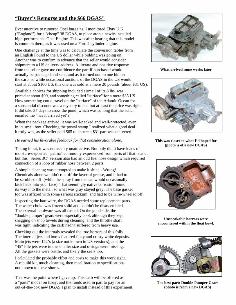
“Buyer’s Remorse and the $66 DGAS" Ever attentive to rumored Opel bargains, I monitored Ebay U.K. ("England") for a "cheap" 38 DGAS, to place atop a newly-installed high-performance Opel Engine. This was after hearing that this model is common there, as it was used on a Ford 4 cylinder engine.
One challenge at the time was to calculate the conversion tables from an English Pound to the US dollar while bidding was going on. Another was to confirm in advance that the seller would consider shipment to a US delivery address. A literate and positive response from the seller gave me confidence the part if purchased would actually be packaged and sent, and as it turned out no one bid on the carb, so while occasional auctions of the DGAS in the US would start at about $100 US, this one was sold at a mere 20 pounds (about $31 US).
Available choices for shipping included airmail of its 8 lbs. was priced at about $90, and something called "surface" for a mere $35 US. How something could travel on the "surface" of the Atlantic Ocean for a substantial discount was a mystery to me, but at least the price was right. It did take 37 days to cross the pond, which was so long that the seller emailed me "has it arrived yet"?
When the package arrived, it was well-packed and well-protected, even in its small box. Checking the postal stamp I realized what a good deal it truly was, as the seller paid $65 to ensure a $31 part was delivered. He earned his favorable feedback for that consideration alone. Taking it out, it was noticeably unattractive. Not only did it have loads of moisture-deposited "patina" commonly experienced from parts off that island, but this "Series 3C" version also had an odd fuel hose design which required connection of a loop of rubber hose between 2 ports.
A simple cleaning was attempted to make it shine - Wrong! Chemicals alone wouldn't run off the layer of grease, and it had to be scrubbed off (while the spray from the can would occasionally kick back into your face). That seemingly native corrosion found its way into the metal, so what was gray stayed gray. The base gasket too was affixed with some serious stickum, and had to be wire-wheeled off.
Inspecting the hardware, the DGAS needed some replacement parts. The water choke was frozen solid and couldn't be disassembled. The external hardware was all rusted. On the good side, the "double pumper" gears were especially cool, although they kept snagging on shop towels during cleaning, and the throttle shaft was tight, indicating the carb hadn't suffered from heavy use.
Checking out the internals revealed the true horrors of this folly. The internal jets and bores featured flaky and crusty white deposits. Main jets were 142’s (a size not known in US versions), and the “45” Idle jets were in the smaller size and o-rings were missing. All the gaskets were brittle, and likely the seals too.
I calculated the probable effort and costs to make this work right. A rebuild kit, much cleaning, then recalibration to specifications not known to these shores. That was the point where I gave up. This carb will be offered as a “parts” model on Ebay, and the funds used in part to pay for an out-of-the-box new DGAS I plan to install instead of this experiment.
What arrived some weeks later
Unspeakable horrors were encountered within the float bowl.
The best part: Double-Pumper Gears (photo is from a new DGAS)
This was closer to what I’d hoped for (photo is of a new DGAS)

Intake Manifold Notes
From the April 1993 OMC Blitz, we adapted these notes by Bob Legere: "Here is one of the biggest limitations of the Opel engine (other than the ignition system). While the cylinder head ports in fact do not flow badly, the intake manifold is a massive restriction (...akin to a marathon runner breathing through a straw...) ...Unfortunately, due to high cost of development, casting, machining and the relatively low volume marketplace, there is no better 2-bbl carburetor intake manifold available...the primary advantage of retaining the standard intake is the fact that it has a plenum— that's the space directly beneath the carb. An intake with a plenum will generally produce more torque than a non-plenum type intake.
Design Identification 1968-1970 GT/Kadett versions are identified by a protruding 1/2-inch “shelf” area which can be seen within the plenum (located nearest the fender). 1971-1972 versions can be identified by the addition of a raised external mount area which has a pair of threaded holes (for mounting of the throttle linkage bracket of the Manta). 1973-1974 versions added a large threaded port hole for an emissions tube (below the booster hose port). There also are noticeable differences in the carb mount height and mount stud lengths, independent of models or years
Intake Manifold Modification Notes **
Warning: Do not do any grinding while intake is on the engine! Engine damage may occur due to ingested metal chips
Mount Area
“Most people have already bolted a Weber 32/36 DGV onto their Opels. (As it’s unfortunate that) the intake slows it down so much, the first (step) - even with a bolt-on Weber replacement - is to match the intake manifold to the throttle bores of the (32/36) Weber. A drill or die grinder with a carbide cutter will cut it away quickly, but a lubricant such as WD-40 should be used to keep the cutter from clogging. If you've got to take the plunge and bolt on a more performance-oriented Weber, such as the 38 DGAS, then considerably more grinding will be required to match the carb to the intake.”
Inner Plenum
“But the major flaw is still the lack of airflow through the intake. The intake manifold represents a loss of approximately 20cfm of air through each port when bolted onto a standard cylinder head. The standard head flows 89cfm of air through each port, so this is a big-time loss, With some careful flow-bench developed porting, I've been able to get back about 6cfm through each runner. Although it will vary with the state of tune of each engine, that's 5-11 horsepower to be gained. Not bad for a little grinding work, but it should be noted that none of the porting was done in the runners, but was instead applied to the plenum area and the radius at the entry to the runners." (Note: Aluminum “wedge” was also added, to increase fuel velocity)
**Based upon comments & illustrations of Bob Legere
Inner Plenum Porting: A Conceptual View **
Diagonal Lines: Areas to be removed via grinding
Dotted Areas: Areas to be built up, with addition of a metal “wedge” at bottom & welding at bolt holes
Runner Areas Porting here generally is not necessary Leave runners rough, to prevent fuel pooling
Throttle Bracket Holes Located here (on 1971-1974 versions)
Mount Area & Inner Plenum Opel tuners advocate grinding
the top mount port wider to match output bores of larger carburetors.
Internal machining is also advocated by experts for better fuel flow and
velocity. See diagram below, for illustration of this general concept.
EGR Port (1973-1974) Some advocate sealing this lower hole with a 1/4” pipe thread plug, or capping its attached tube.
Plenum
Runner Runner
The Opel 1.9L Intake Manifold can be unbolted from the exhaust
for customized service work
www.opelclub.com 07/12

Manifold Adaptations
The 2.2 and 2.4 versions of Opel’s cam-in-head include intake ports which were redesigned and offset.
This means that the original 1.9L and 2.0L intake manifolds and related assemblies cannot be directly bolted up, unless some modifications are performed. This also applies to many aftermarket manifolds, including old-school side draft intake manifolds and some obsolete exhaust header designs.
To further clarify these differences, explanatory diagrams are presented here.
Comparison: Ports & Pin locations of 1.9/2.0 (above) relative to 2.2/2/4 (below),
as seen in manifold mounting gaskets
1.9/2.0
2.2/2.4
Comparison: Manifold Ports & Mounting Pin orientations of 1.9/2.0 (above) to 2.2/2/4 (below)
1.9/2.0
2.2/2.4
Smaller pins
Raised ports
Comparison: Ports & Pin locations of 1.9/2.0 intake manifold port surface,
relative to the port surface of a side-draft intake manifold designed for the 2.2/2/4. (Shown with notations added)
Notes: As seen on the above right, the top of the pin on the right is level with the top
of the ports. The pins are approximately 8mm & 6mm wide, respectively.
If a standard intake is to be paired on a cylinder head with an exhaust header or a “Sprint” type exhaust manifold, you may also have to weld sections
below the intake ports as a “footer” area for additional support.
2.2/2.4
“Footer”
Our experience is that many part sellers, including some at swap meets, some online auction sites and even some specialty part retailers are not always aware of these critical differences. So to avoid being caught with parts you can’t use, you can refer to these diagrams to determine your needs before committing to a sometimes-pricey purchase. The alternative is to only deal with suppliers who are knowledgeable or reputable enough to back up any claims made during a transaction with sufficient post-sale service that will see you through to a successful project completion. (We’ve heard the regrets, from many who tried to save some money upfront, and got burned!)
You may also have an additional challenge, if the tuner shop you contact does business in a different language. You can ask yourself: How good is your knowledge of the terms used as mechanical references in German, Swedish, Danish or Norwegian, and your how detailed is your knowledge of the dialects used by tuners in Finland?
1.9/2.0
Spacer configuration (with “standard” type manifolds)
Connecting bolts & thermostat housing also
require adaptations
www.opelclub.com 07/12
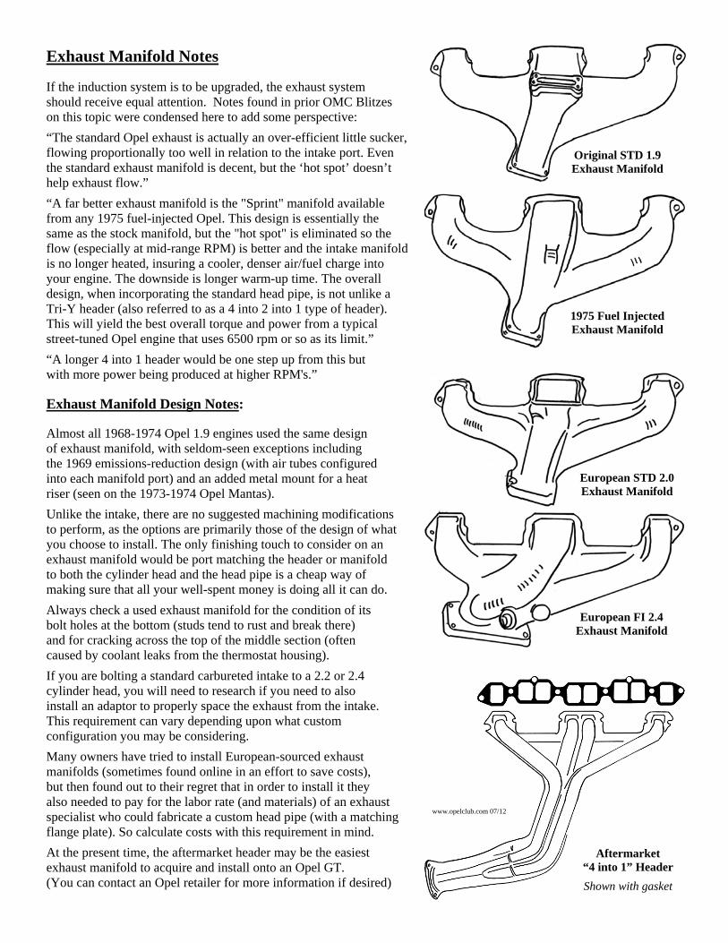
Exhaust Manifold Notes If the induction system is to be upgraded, the exhaust system should receive equal attention. Notes found in prior OMC Blitzes on this topic were condensed here to add some perspective:
“The standard Opel exhaust is actually an over-efficient little sucker, flowing proportionally too well in relation to the intake port. Even the standard exhaust manifold is decent, but the ‘hot spot’ doesn’t help exhaust flow.”
“A far better exhaust manifold is the "Sprint" manifold available from any 1975 fuel-injected Opel. This design is essentially the same as the stock manifold, but the "hot spot" is eliminated so the flow (especially at mid-range RPM) is better and the intake manifold is no longer heated, insuring a cooler, denser air/fuel charge into your engine. The downside is longer warm-up time. The overall design, when incorporating the standard head pipe, is not unlike a Tri-Y header (also referred to as a 4 into 2 into 1 type of header). This will yield the best overall torque and power from a typical street-tuned Opel engine that uses 6500 rpm or so as its limit.”
“A longer 4 into 1 header would be one step up from this but with more power being produced at higher RPM's.” Exhaust Manifold Design Notes: Almost all 1968-1974 Opel 1.9 engines used the same design of exhaust manifold, with seldom-seen exceptions including the 1969 emissions-reduction design (with air tubes configured into each manifold port) and an added metal mount for a heat riser (seen on the 1973-1974 Opel Mantas).
Unlike the intake, there are no suggested machining modifications to perform, as the options are primarily those of the design of what you choose to install. The only finishing touch to consider on an exhaust manifold would be port matching the header or manifold to both the cylinder head and the head pipe is a cheap way of making sure that all your well-spent money is doing all it can do.
Always check a used exhaust manifold for the condition of its bolt holes at the bottom (studs tend to rust and break there) and for cracking across the top of the middle section (often caused by coolant leaks from the thermostat housing).
If you are bolting a standard carbureted intake to a 2.2 or 2.4 cylinder head, you will need to research if you need to also install an adaptor to properly space the exhaust from the intake. This requirement can vary depending upon what custom configuration you may be considering.
Many owners have tried to install European-sourced exhaust manifolds (sometimes found online in an effort to save costs), but then found out to their regret that in order to install it they also needed to pay for the labor rate (and materials) of an exhaust specialist who could fabricate a custom head pipe (with a matching flange plate). So calculate costs with this requirement in mind.
At the present time, the aftermarket header may be the easiest exhaust manifold to acquire and install onto an Opel GT. (You can contact an Opel retailer for more information if desired)
Original STD 1.9 Exhaust Manifold
1975 Fuel Injected Exhaust Manifold
European STD 2.0 Exhaust Manifold
European FI 2.4 Exhaust Manifold
Aftermarket “4 into 1” Header
Shown with gasket
www.opelclub.com 07/12

GT Side Draft Installation Considerations
In old-school tuning, the side-draft carburetor was the “next step up” from the original Opel downdraft design.
Different solutions were proposed by different owners, to the common challenges of:
(1) Tight Space limitations under the hood of the GT (2) Linkage Fabrication (3) Air Filtration (4) Vacuum Supply
As illustrated in the diagrams at right, the typical minimum length of a manifold plus a 4 1/2” for the body of a Weber DCOE carb & spacer leaves a clearance of perhaps a mere 1/2”-2” in some areas for some kind of venturi stack and air filter combination.
This mandates use of a “shorty” style manifold (~4 1/4” or less), with an upward angled to raise the carb end, combined and some fancy homemade engineering to provide a supply of the cool and filtered air which the DCOE design strongly prefers.
Linkage mounting is another issue, as the DCOE rotates in the opposite direction of the original GT carburetor. Function is enhanced through bracketing, as stability is a required for higher performance operation.
Other considerations include a need to connect a hose from a port off of something approximating a “shared plenum,” as the GT brake booster requires a stable vacuum for consistent operation. Not all “shorty intakes” offered such a port, so in some cases one must be made. Finally, a thermostat housing must also be acquired or fabricated, to work within the remaining available space.
Air Filter Projections Illustrates D.S.D conflicts with original body metal
Views
Outline images sampled from prior
OMC Blitzes, and an installed
SSD with a custom “air box” plus filter & custom thermostat
is seen at right
9 1/4” - 10 1/2” (D.S.D.) 11” - 10”
(D.S.D.)
10 1/2” (S.S.D.)
(#1 Intake)
Clearance Dimensions (approximate)
Cyl Head—Body Metal
Actual fit varies by manufacturer: “Old-School” kits were from Cannon, Dellorto, Irmscher, Risent, Steinmetz & TWM induction; Newer models include the "MIDI-Kit" & dBilas.
(SSD = Single Side Draft. DSD = Dual Side Draft)
www.opelclub.com 07/12

Side Draft Installation: GT with 2.4 Engine When Gary Ruyle installed a 2.4 liter engine in his 1972 Opel GT, he added a street-performance level camshaft, electronic ignition, and a 4-into-1 header. But once he drove his GT he felt that even with a 38DGAS Weber that it was somewhat under-carbureted relative to the performance potential of his engine. So Gary obtained an old-school "Pacesetter" brand intake manifold for a side-draft installation onto his Opel engine and got to work. Breaking down each hardware challenge, we can see how Gary’s unique approach to common single-side-draft fitment issues included: (1) Manifold Width & Adaptation As the diagram on the adjoining page indicates, in some places less than 10 inches of lateral space is available. So doing the math, when subtracting the 4 1/2 inches of length of the typical Weber Side Draft carburetor, mandates "shorty" type manifolds (which from every angle cannot exceed 5" where it is bolted onto the side of the Opel cylinder head) are the only style which are workable. Gary selected the "Pacesetter" design which have a top dimension of about 4 1/4" from the cylinder head. This particular design includes a direct fuel feed where one venturi feeds 2 cylinders (differing from other designs which have a "shared" fuel feed. ). But as a manifold designed for the 1.9 Opel cylinder head, it differed from the mount configuration required for the intake ports of the 2.4 (and 2.2) Opel cam-in-head engines. Alteration of the mount required adaptation for a protruding pin (with a mount hole drilled 3/4” deep for addition of a tightly-fitting plug) and addition of a "leg" section below the ports. (This adaptation requirement is better illustrated on an adjoining page). (2) Throttle Linkage How Gary dealt with the “opposite rotation” issue was somewhat unique; He relocated the pivot point of the linkage near its connection from the stub end of the accelerator pedal, retained the original cross-over rod located behind the engine, then through trial and error ground some threaded rods and fittings into a custom connection to the carburetor.
(3) Lateral Support
An important detail that Gary addressed was a need for structural support to supplement the bolts which mount the manifold to the cylinder head. By themselves, the bolts are prone to loosening from engine vibrations, particularly during sudden accelerations (which is the “fun” part, and the point of the upgrade).
To combat this tendency, Gary added a threaded rod which extended from the bottom of the manifold to the a coupling on top of the passenger side motor mount.
This provides added vertical support from a direction which is perpendicular to the mount bolts. The threaded rod application also provides a means for adjustment, should the mount angle shift over time.
Throttle Linkage (driver’s side)
Mount Rod
(passenger side)
Motor Mount
www.opelclub.com 07/12

(4) Venturi Length and Air Filtration To fit within the tight space limitation of the GT, Gary found it necessary to cut 1" from the shortest-length venturi available to a total 3/4" length. (Among many interchangeable parts offered for the Weber DCOE series, there is a choices of venturi length, but most will not fit into the GT.) Gary selected a choke size of 38mm, which is within the allowable 20% variance from the 45mm main venturi ports of the DCOE. His main and idle jet sizes were selected after a research of applicable Tuning notes for the SSD on an Opel 2.4 (found on the internet). Gary also determined that conventional air filters could not fit within the available space. He instead obtained a pair of tightly-woven "high flow" wire air filters to fit over his velocity stacks (they resemble those offered online by BBR of Kansas).
(5) Cold Air Ducting Side draft carburetors in general run better with a denser fuel mixture aided by delivery of colder air. To achieve this in a GT, Gary added a duct hose from the original air filter canister forward to the front of the car. Then he designed and installed a custom-cut metal plate, which he bolted to a portion of the body metal. He left the rear port of the air filter canister open and helped route its air output to the carb to provide cooler air to the area where the intakes could make use of it without restriction. A square cut rear area acts as an “exhaust port” to further direct airflow.
Comparison: Roger Lee’s Side Draft Setup
Note that the above installation with extended venturi’s will not fit within the tight space of an unmodified Opel GT!
(From: OMC Blitz, Jan 1986)
Additional adaptations (seen above) included addition of a common small block Chevy “port filter” (of the type marketed by Mr. Gasket) for the
thicker of the hose inlet ports on the valve cover.
Results
Gary says he adjusts his idle speed to a minimum of 1200 rpm's and has noted smooth acceleration
throughout the power band of his engine.
In the city he estimates he gets about 20 mpg and on the highway his mileage is about 25 mpg.
Airflow
Bolts
Bolts Duct Hose
Body Metal
Cut
Plate Aircan
www.opelclub.com 07/12

Want a V6 (or a V8) ?
Many Opel owners over the years have looked under the hood and thought “I can fit a __________ in there”!
The motivations can vary: Aside from the desire for more power, owners often are looking for a motor they are more familiar with, or they are seeking a project to challenge then, or they are looking to build a street racer on the cheap with an extra drivetrain lying around. Many drivetrains will in fact fit the GT (or will fit with some alterations), but to base a common conception within some hard realities, below are some considerations worthy of discussion (before making that first cut). The Case Against It
Long-time Opelers commonly advise newer owners against coverting to a non-Opel engine conversion for various reasons. The first is size: Before any particular drivetrain can be considered, it needs to be measured on all sides to assure fit and clearance on the chassis at critical locations (also ask: does the shifter location fit the original hole in the transmission tunnel, and will it fit under the original hood or under the “bubble” of a raised fiberglass “sport” hood)?
Other specific considerations are presented here, in relation to an underhood diagram:
Additional upgrades (not illustrated here) may be necessary, including body reinforcement, replacement of the rest of the driveline including the driveshaft and rear axle, and installation of larger brakes. Sensors may also require adaptations to work with original Opel dashboard gauges, or the gauges may have to be replaced with generic models.
If you’re going to do it, why not go “All The Way” ?
Measure all clearances before making a cut!
~28 1/4” edge - edge
The Finished Product ?
Aside from the muttered denigrations overheard from Opel purists, V6-V8 conversions can upset the original balance and handling (which was one of the signature lures of the original GT).
Owners of conversion projects have reported driving responses to be “nose-heavy” which suffer greatly on curves, and of tiring from the constant noise and chassis vibration felt while on the road. In worst-case scenarios, windshields get cracked from body twist!
The greatest downside then follows: The resale market.
Relatively few buyers will even consider a “Franken-Opel” and even fewer respond positively to being asked to help recoup its sellers’ investment. The sole exception is the full-bore GT dragster market—which has its own unique fan base.
Steering Shaft:
Perhaps the greatest obstacle to a “balanced” drivetrain retrofit, retaining the shaft requires installing a very narrow exhaust manifold (with the pipe routed around the front of the engine) or articulating the shaft using u-joints (which provides a "notchy" road response).
Conversion to power steering is a common “solution,” but has a significant drawback: It also eliminates most road feel when driving.
Cooling: Requires radiator upgrade (and likely relocation), electric fan and ductwork. Removal of the crossbar can negatively affect structural stability of the chassis
Throttle Linkage: Requires adaptation, often with addition of a cable assembly
Suspension: No upgrades are available to support added front-end weight. The shock towers and a-arms are too weak to support an independent suspension without extensive fabrications.
Mounts: Size and materials are insufficient to prevent vibrations from resonating throughout chassis.
Firewall: Often the metal has to be cut and re-welded for adequate clearance. Heat and noise often penetrate any shielding placed here.
~15 1/2”
Internal Space: Varies from 25”- 26” at widest, tapering to 18”- 20” at firewall, to 16” - 14” - 10” in trans. tunnel. (less on driver’s side at steering shaft, and near clutch/speedo/headlight cables).
Max. height is ~21”-24” under the hood.
www.opelclub.com 07/12

Valve Cover Notes
Critical to any higher-performance engine operation, is adequate “breathing” through the hose ports of the valve cover.
If these ports cannot breathe, the engine will become over-pressurized and oil may start to be forced to seep out through gasket areas.
1968-1972
Manifold Vacuum Retard Port
1973-1974
Original “Solex” Style Filter
On original air filter systems (or with adaptors to the Weber carb),
this is a formed hose that connects to the metal “cap”
that sits on top of the carburetor.
Hose connects here
“Weber Carb” Style Filter
On the basic Weber air filter, this a short length of a thick
flexible hose connects to a plastic “elbow”.
Hose connects here
Thinner Hose
This (~7/32”ID, ~13/32”OD) hose connects to a thin vacuum port
on intake manifold.
This port was located in two different places on Opel manifolds.
1973-1974 Manifolds
On 1973-1974 manifolds, the thinner hose connects to
a port located on the engine side of the manifold.
1968-1972 Manifolds
On 1968-1972 manifolds, the thinner hose connects to a port located
below a thick brake booster hose.
Thicker Hose
This (~15/32” ID, ~3/4”OD) hose connects to an inlet on
the air filter system
The inlet location varies with the style of air filter system installed on an
Opel..
Valve Cover Hose Connections
Required maintenance involving the valve cover includes periodic disassembly and
cleaning of internal screen elements.
Disassembly Remove the valve cover, remove the ten small 8mm
headed bolts from the inside, then lift off the baffle plate. Briefly soak the wire mesh screens in a solvent solution,
only long enough for caked oil deposits to be able to be shaken loosen from the screen pieces.
Do not leave in solvent any longer than needed, to avoid disintegration of the screens. If replacing screens, do not use “supermarket type” steel wool!
Hoses It is important to “vent” the valve cover, by attaching
hoses as shown below. Contrary to rumor, there is No “PCV” valve installed on either the ports or hoses.
Baffle Plate
Underside of valve cover & 2 mesh screens
www.opelclub.com 07/12

(Index: Selected Prior OMC Blitz Engine Performance Articles) Nov 1999, March 2000, Sept 2000 3.1L V6 in a GT tech article, parts one, two and three, 6 pages (illustrated) Mike P. describes considerations of various engines, and conversion to a 1992 Camaro engine in a GT. Photos included. Middle section concerns wiring adaptations, and final section covers firewall/pedal area modifications, custom engine crossmember, trans mount, Fiero exhaust manifolds, Chevy S-10 bellhousing and clutch, and custom exhaust pipes.
July 1999 GT 4-6 cylinder and V-8 Engine swaps, 2 pages Discussion of pros and cons of various GT engine swaps, notes 2.8L V-6 and Buick 215 V-8's fit GT's better than most, also the bolt-on Opel 2.2 Liter 4cylinder receives compliments.
July 1996 and Aug 1996 "Dyno Time, Parts I & II"; 3 pages Details of a custom 140+ horsepower engine build: 2.0 liter short block, notes on large valve installations and porting of a 1.5 Opel cylinder head, mods of a 38 DGAS Weber carb, cam specs. Part II includes details on refinements to 155 horsepower/160 lb. ft. torque output Opel engine.
July 1995 Opel V6 and V8 Engine projects; 4 pages (illustrations) Includes basic mounting notes and photos of V-6 and V-8's installed in Opel GT's, including: 1978 Ford 2.8 liter V-6, Chevy 3.3 liter V-6, Chevy 262ci 4.3 liter V-6, 1984 Chevy 2.8 liter V-6, 1982-1984 Chevy S-10 2.8 liter V-6, Buick 215ci V-8, Chevy 283ci V-8, Chevy 305ci V-8, and different examples of Chevy 350ci short-block V-8's.
June 1992 Popular GT Engine Swaps (Opel 2.0-3.0's & US V6-V8's); 4 pages Includes photos and descriptions of Opel 1.9, 2.0. 2.2 and 2.4 liter engines (which require some adaptation to be bolt-on replacements in Opel GT's), as well as 2.0 16-valve, 2.8-3.0 6-cylinder and 3.0 24-valve European Opel engines. Non-Opel engines described are the Mazda rotary 13B, 3.8 liter Buick V-6, 2.8 liter Ford V-6, 2.8 liter GM motor, Buick/Rover 215 cubic inch V-8, Ford 289/302 cubic inch V-8, and Chevy 283/350 cubic inch small-block V-8. Descriptions are not in detail, so although there are size and power output notes, this article alone is not all the information you need before starting an Opel engine swap project.
Ebay image of a 350 V8 installed in Opel GT
Note engine bay alterations and engine extension rearward into firewall area
Opel GT V8 Interior View Note elevated shifter location
O P E L G T S O U RC E Open Mon-Fri 8am - 5pm Pacific 9am - 6pm Mountain 10am - 7pm Central 11am - 8pm Eastern
Catalog: $4.00
Mailing Address: P.O. Box 4004, Sonora, CA 95370 USA UPS Shipping Address: 18211 Zeni Lane, Tuolumne, CA 95379 USA
New, Reproduction, Used & High Performance parts for: Opel GT, Manta A, 1900 Sedan, Wagon & Kadett B
Direct Importer. Same Day Shipping policy. We accept Visa, Master Card, AMEX & Discover. Serving the Opel Community Since 1987
Orders: 1-800-673-5487 Info: 1-209-928-1110 Fax: 1-209-928-3298 Web: www.opelgtsource.com Email: [email protected]
YOUR ONE STOP OPEL SHOP
VISIT OUR WEBSITE: WWW.OPELSUNL.COM
COMPLETE PARTS &
SERVICES FOR ALL OPELS
FROM 1960 TO 1980
“If You Bought It Somewhere Else, You
Paid Too Much”
1310 N. TAMARIND AVE. RIALTO, CA 92376 PHONE: 909-355-OPEL FAX: 909-355-6557
Sales Brochures
OPEL ORIGINAL sales brochures showing all Opel models, interiors, features for the year. Great for Restorations or Gifts! ALL PRICES PER YEAR: 1947-49, $40; 1950-54, $35; 1955-64, $25; 1965-69, $18; 1970-present, $15. Add $4.95 shipping. Specify year & model. VlSA/MC. Also have literature, manuals, all cars, trucks, motorcycles, world-wide. Visit our website: http://www.autolit.com Walter Miller, 6710 Brooklawn, Syracuse NY 13211 Tele: (315) 432-8282 Fax: 315-432-8256 E-mail: [email protected]
Classified Ads
The Opel Motorsport Club offers Advertising as a service to its members and does not endorse or bear responsibility
for any claims made by advertisers. OMC strongly suggests exercising caution in any transactions for items,
including: Checking out Vendor reputation on Internet discussion boards such as at: www.opelgt.com
www.opelclub.com 07/12