Embed Size (px)
Citation preview
1
Abstract This paper describe a periodically oscillating two trailing edge flaps based on shape memory alloy actuator, which is simple to install in the wing, to understand the lift variation according to the flap motions. A prototype wing model with two flaps actuated by SMA wires was designed, and fabricated. Its operational performances were tested with and without flow conditions. Two linear Hall-effect sensors were employed and calibrated to control each flap. A proportional-integral-derivative control method was implemented to control the motion of the flaps accurately. As a result, the two flaps were successfully controlled simultaneously in various periodic motions such as triangular and sine waves. Subsequently, lift and drag forces corresponding to the various periodic flap motions were investigated experimentally through wind tunnel tests.
1 Introduction Control of trailing vortex wakes of lifting surfaces has been an important issue in many applications. A variety of topics involved with mitigation of the undesirable effect of tailing vortex wakes have been studied by previous researchers. This technology may be applied to both civilian industries as well as the military. In June 1994, the U.S. Federal Aviation Administration (FAA) modified the required separation standards from 4 to 6 miles for small airplanes from the previous 3 miles due to the exceptionally strong vortex wake hazard posed by the wake of the Boeing 757 [1]. Until recently, FAA have been developed and modified wake turbulence separation standards between leading and following aircraft. Therefore, this
technology has the potential of reducing hazard on an aircraft from the strong trailing vortex produced by other heavy civil airliners during take-off and landing. Mitigation of vortex wakes can be eventually contributed to save the cost incurred from the flight delays and capacity limitations of airport. Studies on mitigation of trailing vortex wakes can be classified into two strategies: passive methods and active methods. Winglets, which has been developed in various shapes as blended winglet from Aviation Partners, Inc., wingtip fence used in some Airbus airplane, and raked wingtip developed by Boeing Company, are the typical examples of the passive methods [2, 3]. Unique wingtip devices such as spiroid winglets [4] that look like a large loop of rigid ribbon material have been developed and planned for commercialization. These methods allow lifting surfaces to have alleviated trailing vortex wakes compared to those of untreated lifting surfaces and rely on the dissipative effects from the interactions between two or more pairs of opposite-signed counter-rotating vortices established behind the lifting surfaces (i.e., naturally arising instabilities lead their mutual destruction) [5]. The latter methods intentionally induce the instabilities of the vortices from the near field. These methods include differentially and time-dependently deflecting control surfaces [6], oscillating winglet flaps [7], span-wise or angled air blowing method at the tip of the wing [8], and active gurney flaps [9]. In this paper, a method of differentially and time-dependently deflecting flaps was selected for the research topic. Multiple flaps are more effective than single flap in terms of triggering the instability of the trailing vortex wakes. However, a number of actuators corresponding to the number of flaps or
PERIODICALLY OSCILLATING TWO TRAILING EDGE FLAPS ACTUATED BY SMA WIRES
Woo-Ram Kang, Duck-Joo Lee Korea Advanced Institute of Science and Technology
Keywords: shape memory alloy, trailing-edge flap, aerodynamics
WOO-RAM KANG, DUCK-JOO LEE
2
additional devices for coupling the motion of the flaps through a single actuator should be used to operate the multiple flaps. These methods involve some problems such as complexity of operating mechanism and increase in weight of the operating systems. Hence, there have been a lot of attempts to develop smart wings using various smart materials by past researchers. A candidate of smart materials or actuators for smart wings include piezoelectric ceramics (PZT), pneumatic artificial muscles (PAMs), and shape memory alloys (SMAs). Among them, actuators driven by SMA provide the highest power-to-weight ratio [10] at low force ranges, and can be used as "direct drive linear actuators" with little or no additional motion reduction or amplification hardware [11]. Hence, the employment of SMA allows actuating system to be simplified and miniaturized in comparison with the conventional actuating system and use of other smart materials actuating systems. According to previous researches, trailing edge flap mechanisms based on a various type of SMA actuators such as spring type [12], ribbon type [13] and wire type [14-15] of SMA actuators have been proposed and its functional operations have been demonstrated. Most published papers focus on variable-camber trailing edge continuously morphing its shape smoothly to achieve improved aerodynamic performances compared to modern flap systems. In 1996, Quackenbush et al. [1] proposed a concept for controlling the vortex wake using SMA-actuated trailing edge flap. They showed the feasibility of developed smart vortex leveraging tab (SVLT) by testing its operational performance in the water tunnel [16]. Current research studies focus on a demonstration of differentially and time-dependently oscillating flaps for validation of its operational performances rather than the vortex wake structures. In this paper, a prototype wing model with two flaps actuated by shape memory alloy wires was designed, and fabricated. To control the motion of the flaps, two Hall-effect sensors were installed in each flap and calibrated in degree unit. Tracking control tests for the fabricated wing model were performed in periodic motions such as triangular and sine waves and both with and without flow conditions.
Subsequently, unsteady aerodynamic forces corresponding to the various periodic flap motions were investigated.
2 Wing model with two flaps
2.1 SMA actuator SMA, one of the popular smart material, is an alloy that have unique effect known as shape memory effect (SME). The SME can be explained by phase transformation between the SMA’s two crystalline phases: martensite and austenite phases. Martensite, which is observed at a lower temperature, transforms to austenite upon heating. This is because, the austenite is stable at a higher temperature. Conversely, the inverse transformation occurs as its temperature cooled down. The properties of martensite is mechanically weak. For that reason, pseudo-plastic deformation (residual strain) easily occurs due to the applied loading stress and a number of variants is observed. The martensite having a force-induced residual strain is called the detwinned martensite. The residual strain can be recovered by heating the SMA. From a macroscopic point of view in particular, wire type of SMA contracts and relaxes one-dimensionally like muscles with 5 or 6 % strains, so it can be implemented to diverse actuating systems. These characteristics allow the SMA to be used as an actuator. In this study, Flexinol wires produced by DYNALLOY, Inc. [17] were employed as an actuator. Among the products having various diameter size, a Flexinol wires which has 0.203 mm in diameter was selected.
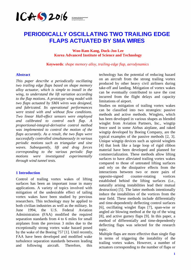
2.2 Flap mechanism and wing design Fig. 1 (a) shows the designed wind tunnel test model. The cross section of the wing model was designed based on NACA0012 airfoil. The chord and span length of the wind tunnel test model were 250 mm and 300 mm, respectively. Two flaps were partially and symmetrically located at the middle of the span. Both two flaps has the same size and which chord and span length were 78 mm and 100 mm, respectively.
3
PERIODICALLY OSCILLATING TWO TRAILING EDGE FLAPS ACTUATED BY SMA WIRES
Flap mechanism can be explained by fig. 1 (b) which shows the cross section view of the wing model. Upper and lower figures show the cross section of flap tip region and the region slightly apart from the flap tip, respectively. Basically, the flap system introduced in this paper was hinged to the rear section of the wing and actuated downward as conventional flap systems. Flap deflection angles were limited from 0 to 30 degrees. A total of four SMA wire actuators were installed in a U-shape and each flap is operated by two SMA wires, as shown in fig. 1. Both ends of the SMA wires were fixed at the lower part of one of the spars, and the middle section of the SMA wire was fixed at the lower part of the cylindrical structure of the flap by winding up once. Electric wires for resistive heating (Joule heating), which is generally used in increasing the temperature of the SMA wires, were connected with the fixed points of both ends of the SMA wires. A total of 4 linear spring, which has 2 mm diameter and 50 mm of initial length, were installed with 16 mm pre-extension for transforming the SMA wire. Thus, the flaps were operated as a pulley system. For feedback control of the flaps, two pairs of Hall-effect sensors and neodymium magnet were implemented in the wing model. The linear Hall-effect sensor IC WSH138 which has a linear response with respect to magnet field strength, were fixed in the main wing frame. The neodymium magnets were installed in the cylindrical parts assembled with the flaps and rotates with flaps when the flaps are actuating. Therefore, each Hall-effect sensor generates the feedback signals by detecting changes in the magnetic field strength from the flap deflections.
(a) Wing configuration.
(b) Cross section view. Fig. 1. Wing model and flap mechanism.
3 Control strategy and experimental setup
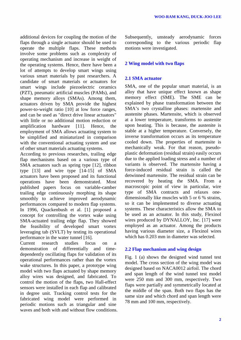
3.1 PID control method SMAs have non-linear behavior and transform hysteresis come from between the heating and cooling transitions. That means that the constant inputs involved with the SMAs’ temperature cannot control the specific deformation of them. The unpredictable factors such as ambient temperatures and external loading conditions. In this research, PID control method was implemented to control the SMA actuated flaps accurately. Fig. 2 shows the block diagram of the control system of the wing model with two flaps. The control system has been implemented in the dSPACETM DS1103 system, which provides unparalleled number of I/O interfaces and allows a various processes in real time. A two-channel voltage controller composed of an operational amplifier (OP-AMP) and metal oxide silicon field effect transistor (MOSFET) was constructed to operate the SMA actuators by resistive heating. The device amplifies the digital-analog converter (DAC) voltage signal from DS1103 and applies the amplified voltages to SMA actuators as a controllable DC power supply. The control system shown in fig. 2 was implemented in MATLAB/Simulink. The transfer function of the PID controller is expressed as in equation (1).
1( )c P I DNsG s K K K
s s N = + + +
(1)
where N represents the filter coefficient. The filter coefficient is set at a large number so as to get a good approximation. This is the so-called
WOO-RAM KANG, DUCK-JOO LEE
4
“soft-derivative” approximation, which acts as a first-order low pass filter to prevent undesirable noise amplification produced in the discontinuous control signal such as step input. It is found that the action of the approximate derivative approaches the pure derivative when N is infinite [18]. The control time step t∆ is 0.001 seconds, and the filter coefficient N is taken to be 100. In eq. (1), KP, KI and KD represent the proportional, integral, and derivative gain, respectively. These gains were obtained by a trial and error method with consideration as to have no overshoot and no oscillation, since these two conditions can cause negative effects to aircraft during actuations. The determined gains for each flap are listed in table 1.
Table 1. Determined gains for control. Gains ,P iK ,I iK ,D iK
Flap 1 0.35 0.14 0.07 Flap 2 0.40 0.15 0.07
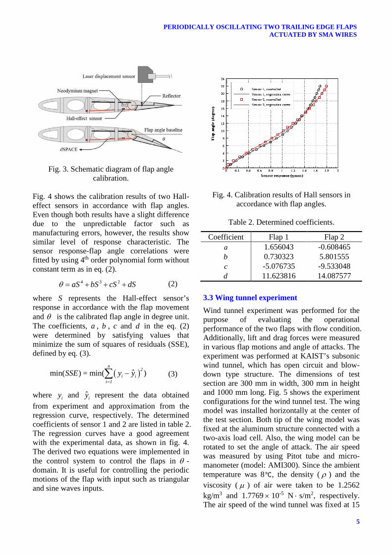
3.2 Flap angle calibrations Two Hall-effect sensor WSH138 that has a linear response with respect to magnetic field strength, were used to control each flap individually. The sensor has a flat response up to 23 kHz, high sensitivity of 8.15 mV/G and good operability in
a broad temperature range from -40 to 125 . In order to control the flap motion accurately, the responses of two Hall-effect sensors were calibrated in units of degree. Fig. 3 schematically shows a diagram of flap angle calibration. A laser displacement sensor (model LK-081) was externally set up to detect the flap motions. The calibration process was carried out before assembling the wing skin. An additional structural component illustrated by a bold line in fig. 3 was constructed in the middle of the flap to measure the flap angle accurately. This component allows the laser sensor to measure the flap angle baseline between the flap hinge and trailing edge. The flap angle can be simply calculated by using trigonometric function. Moreover, the flap angle calibrations were performed with the following procedures: I. Fix the two flap to move as one, and constitute a single PID control system to actuate a total of four SMA wires installed in the wing model at a time, II. Deflect the two flap at the same time from 0 to 22 degrees with intervals of 1 degree using a laser displacement sensor with PID control, III. Collect two Hall-effect sensor signals corresponding to controlled flap angles. Here, the two sensor outputs at 0 flap angle condition were set to 0. IV. Derive each fitting curve equation using the data obtained from the two sensors.
Fig. 2. Block diagram of the PID control system.
5
PERIODICALLY OSCILLATING TWO TRAILING EDGE FLAPS ACTUATED BY SMA WIRES
Fig. 3. Schematic diagram of flap angle calibration.
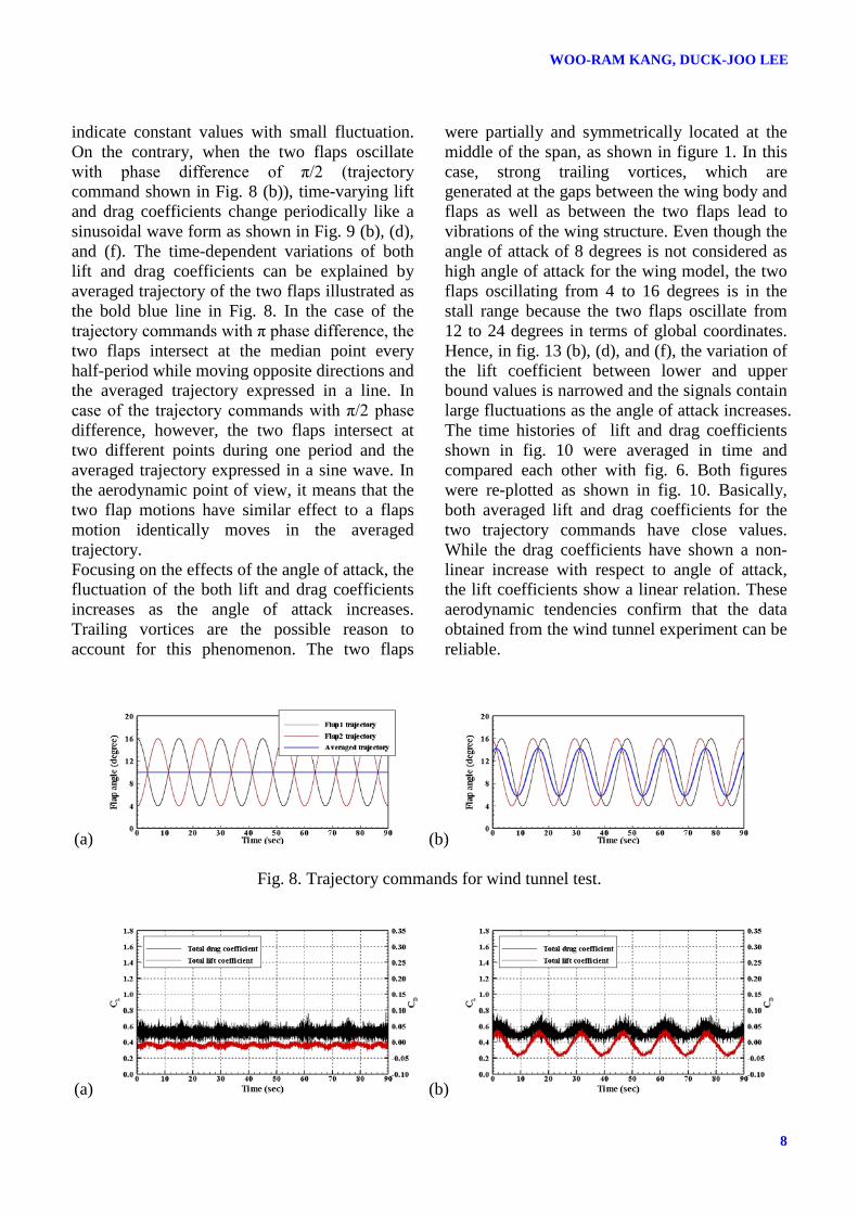
Fig. 4 shows the calibration results of two Hall-effect sensors in accordance with flap angles. Even though both results have a slight difference due to the unpredictable factor such as manufacturing errors, however, the results show similar level of response characteristic. The sensor response-flap angle correlations were fitted by using 4th order polynomial form without constant term as in eq. (2).
4 3 2aS bS cS dSθ = + + + (2)
where S represents the Hall-effect sensor’s response in accordance with the flap movement and θ is the calibrated flap angle in degree unit. The coefficients, a , b , c and d in the eq. (2) were determined by satisfying values that minimize the sum of squares of residuals (SSE), defined by eq. (3).
( )min( ) = min( )n
2i i
i 1
ˆSSE y y=
−∑ (3)
where iy and iy represent the data obtained from experiment and approximation from the regression curve, respectively. The determined coefficients of sensor 1 and 2 are listed in table 2. The regression curves have a good agreement with the experimental data, as shown in fig. 4. The derived two equations were implemented in the control system to control the flaps in θ -domain. It is useful for controlling the periodic motions of the flap with input such as triangular and sine waves inputs.
Fig. 4. Calibration results of Hall sensors in accordance with flap angles.
Table 2. Determined coefficients.
Coefficient Flap 1 Flap 2 a 1.656043 -0.608465 b 0.730323 5.801555 c -5.076735 -9.533048 d 11.623816 14.087577
3.3 Wing tunnel experiment Wind tunnel experiment was performed for the purpose of evaluating the operational performance of the two flaps with flow condition. Additionally, lift and drag forces were measured in various flap motions and angle of attacks. The experiment was performed at KAIST’s subsonic wind tunnel, which has open circuit and blow-down type structure. The dimensions of test section are 300 mm in width, 300 mm in height and 1000 mm long. Fig. 5 shows the experiment configurations for the wind tunnel test. The wing model was installed horizontally at the center of the test section. Both tip of the wing model was fixed at the aluminum structure connected with a two-axis load cell. Also, the wing model can be rotated to set the angle of attack. The air speed was measured by using Pitot tube and micro-manometer (model: AMI300). Since the ambient temperature was 8 , the density ( ρ ) and the viscosity ( µ ) of air were taken to be 1.2562 kg/m3 and 1.7769 × 10⁻⁵ N ⋅ s/m2, respectively. The air speed of the wind tunnel was fixed at 15

WOO-RAM KANG, DUCK-JOO LEE
6
m/s. Thus the corresponding Reynolds number is about 265,000.
Fig. 5. Wind tunnel experiment setup.
To verify the experiment data obtained from the wind tunnel test, the lift and drag coefficients of the wing model for the flap is not deployed were measured and compared. The wind tunnel test was carried out at a range of angles of attack from -4 to14 degrees, and the results are shown in fig. 6. An experimental data [19] was used as reference to compare the test results with other study. NASA technical note reported the airfoil section characteristics as affected by variations of the Reynolds number. One of the results in the technical note shows the aerodynamic coefficients of the NACA0012 airfoil at Reynolds number of 330,000. The slope of the lift coefficient and drag polar curve obtained from the experiment is found to be in good agreement with the results from the experiment of Jacobs.
(a)
(b)Fig. 6. Comparison of lift and drag coefficients.
4 Results and discussions
4.1 Tracking control test Fig. 7 shows the tracking control test results of the two flaps for the triangular and sine wave motions. The movements of the two flaps has phase differenceπ . Flap amplitude were set from 4 to 12 degree to verify that the upper and lower bound values of the wave inputs to be controlled. Control tests were carried out for the following three frequencies: 1/40 Hz, 1/30 Hz, and 1/20 Hz to investigate the response characteristic of the flaps with respect to various frequencies of the wave input. The triangular wave results show the unsatisfactory agreement especially at the lower bound values due to its sharp wave form. Sine waves input, which consist of only smooth curves, shows satisfying results at both upper and lower bound values compared to triangular waves. This phenomena clearly appears when the period becomes shorter. The root mean square (RMS) errors were calculated to compare the results obtained from the tracking control test quantitatively. The RMS errors corresponding to the results are listed in table 3. Table 3 shows that the RMS errors increase as the period and the flap amplitude increase. As a results, we confirmed that the two flaps can be controlled in sine and triangular waves with an accuracy of less than 1 degree of RMS error.

7
PERIODICALLY OSCILLATING TWO TRAILING EDGE FLAPS ACTUATED BY SMA WIRES
Fig. 7. Tracking control results of the two flaps.
Table 3. RMS errors for the periodically oscillating two flaps.
Flap amplitude (deg.)
Periods (sec.)
RMS error (triangular wave) RMS error (sine wave) Flap 1 (deg.) Flap 2 (deg.) Flap 1 (deg.) Flap 2 (deg.)
From 4 to 12 40 0.3690 0.3136 0.3644 0.3042 30 0.4733 0.4539 0.4660 0.4363 20 0.6497 0.6061 0.7018 0.6586
From 4 to 16 40 0.4421 0.4045 0.4173 0.3914 30 0.5878 0.5358 0.5347 0.5381 20 0.8195 0.7553 0.9174 0.8126
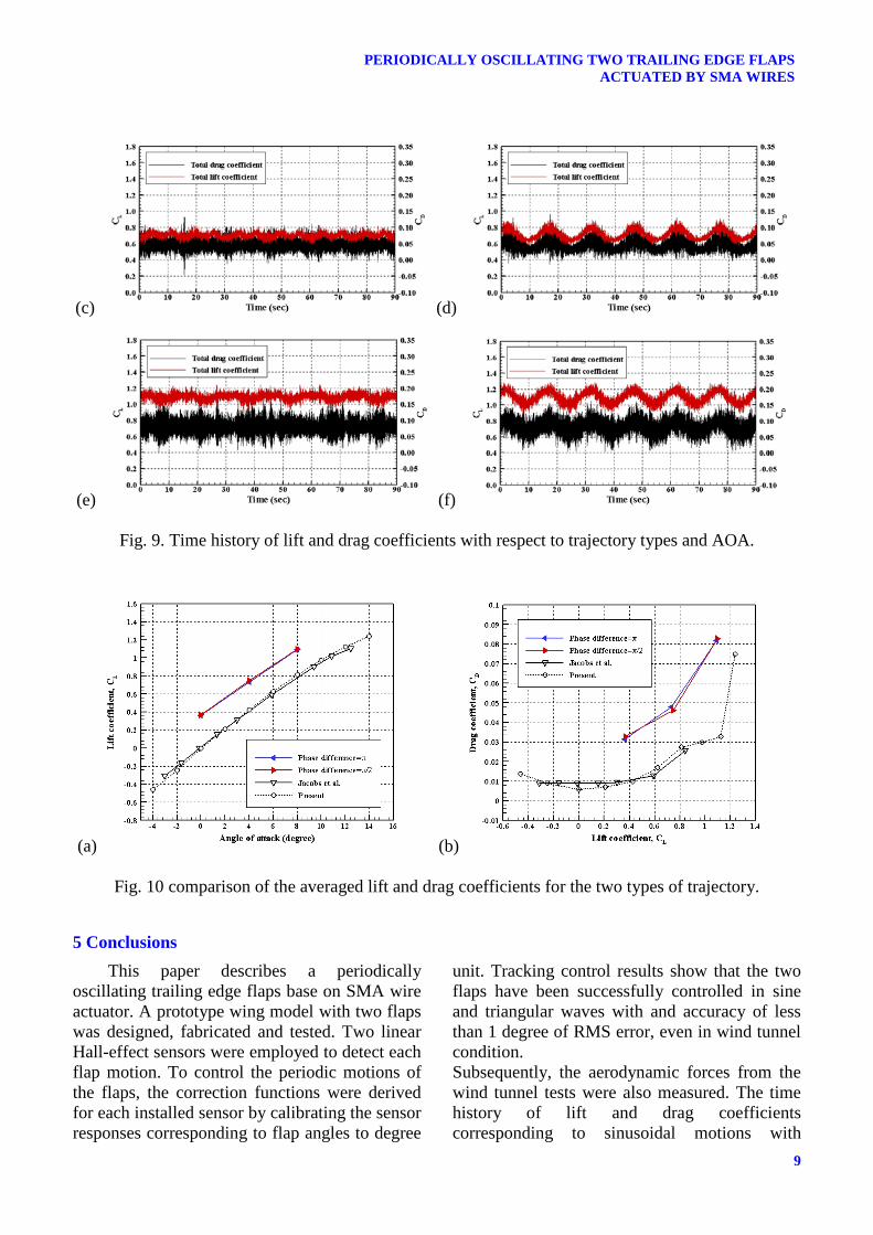
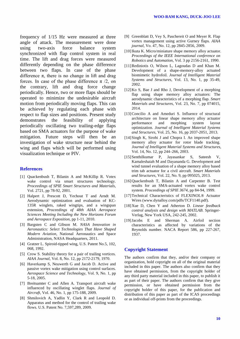
4.2 Aerodynamic characteristics The time history of lift and drag coefficients corresponding to sinusoidal motions with 1/15 Hz were measured by using the two-axis force balance system synchronized with flap control system. Fig. 8 shows two types of trajectory commands for wind tunnel experiment. The first type is the sine trajectories with phase difference π, and the other type is the same trajectories but with phase difference π/2. Experiments were
carried out for the following three angle of attacks, 0, 4, and 8 degrees. The air speed of the wind tunnel was 15 m/s (Re ≈ 265,000). Fig. 9 shows the time history of lift and drag coefficients. Fig. 9 (a), (c), and (e) are the results for the same trajectory commands having phase difference of π at 0, 4, and 8 angle of attack conditions, respectively. In these conditions, both time-varying lift and drag coefficients
WOO-RAM KANG, DUCK-JOO LEE
8
indicate constant values with small fluctuation. On the contrary, when the two flaps oscillate with phase difference of π/2 (trajectory command shown in Fig. 8 (b)), time-varying lift and drag coefficients change periodically like a sinusoidal wave form as shown in Fig. 9 (b), (d), and (f). The time-dependent variations of both lift and drag coefficients can be explained by averaged trajectory of the two flaps illustrated as the bold blue line in Fig. 8. In the case of the trajectory commands with π phase difference, the two flaps intersect at the median point every half-period while moving opposite directions and the averaged trajectory expressed in a line. In case of the trajectory commands with π/2 phase difference, however, the two flaps intersect at two different points during one period and the averaged trajectory expressed in a sine wave. In the aerodynamic point of view, it means that the two flap motions have similar effect to a flaps motion identically moves in the averaged trajectory. Focusing on the effects of the angle of attack, the fluctuation of the both lift and drag coefficients increases as the angle of attack increases. Trailing vortices are the possible reason to account for this phenomenon. The two flaps
were partially and symmetrically located at the middle of the span, as shown in figure 1. In this case, strong trailing vortices, which are generated at the gaps between the wing body and flaps as well as between the two flaps lead to vibrations of the wing structure. Even though the angle of attack of 8 degrees is not considered as high angle of attack for the wing model, the two flaps oscillating from 4 to 16 degrees is in the stall range because the two flaps oscillate from 12 to 24 degrees in terms of global coordinates. Hence, in fig. 13 (b), (d), and (f), the variation of the lift coefficient between lower and upper bound values is narrowed and the signals contain large fluctuations as the angle of attack increases. The time histories of lift and drag coefficients shown in fig. 10 were averaged in time and compared each other with fig. 6. Both figures were re-plotted as shown in fig. 10. Basically, both averaged lift and drag coefficients for the two trajectory commands have close values. While the drag coefficients have shown a non-linear increase with respect to angle of attack, the lift coefficients show a linear relation. These aerodynamic tendencies confirm that the data obtained from the wind tunnel experiment can be reliable.
(a) (b)
Fig. 8. Trajectory commands for wind tunnel test.
(a) (b)
9
PERIODICALLY OSCILLATING TWO TRAILING EDGE FLAPS ACTUATED BY SMA WIRES
(c) (d)
(e) (f)
Fig. 9. Time history of lift and drag coefficients with respect to trajectory types and AOA.
(a) (b)
Fig. 10 comparison of the averaged lift and drag coefficients for the two types of trajectory.
5 Conclusions This paper describes a periodically
oscillating trailing edge flaps base on SMA wire actuator. A prototype wing model with two flaps was designed, fabricated and tested. Two linear Hall-effect sensors were employed to detect each flap motion. To control the periodic motions of the flaps, the correction functions were derived for each installed sensor by calibrating the sensor responses corresponding to flap angles to degree
unit. Tracking control results show that the two flaps have been successfully controlled in sine and triangular waves with and accuracy of less than 1 degree of RMS error, even in wind tunnel condition. Subsequently, the aerodynamic forces from the wind tunnel tests were also measured. The time history of lift and drag coefficients corresponding to sinusoidal motions with
WOO-RAM KANG, DUCK-JOO LEE
10
frequency of 1/15 Hz were measured at three angle of attack. The measurement were done using two-axis force balance system synchronized with flap control system in real time. The lift and drag forces were measured differently depending on the phase difference between two flaps. In case of the phase difference π, there is no change in lift and drag forces. In case of the phase difference π /2, on the contrary, lift and drag force change periodically. Hence, two or more flaps should be operated to minimize the undesirable aircraft motion from periodically moving flaps. This can be achieved by regulating each phase with respect to flap sizes and positions. Present study demonstrates the feasibility of applying periodically oscillating two trailing-edge flaps based on SMA actuators for the purpose of wake mitigation. Future steps will then be an investigation of wake structure near behind the wing and flaps which will be performed using visualization technique or PIV.
References [1] Quackenbush T, Bilanin A and McKillip R. Votex
wake control via smart structures technology. Proceedings of SPIE Smart Structures and Materials, Vol. 2721, pp 78-92, 2001.
[2] Halpert J, Prescott D, Yechout T and Arndt M. Aerodynamic optimization and evaluation of KC-135R winglets, raked wingtips, and a wingspan extension, Proceedings of 48th AIAA Aerospace Sciences Meeting Including the New Horizons Forum and Aerospace Exposition, pp 1-11, 2010.
[3] Bargsten C and Gibson M. NASA Innovation in Aeronautics: Select Technologies That Have Shaped Modern Aviation, National Aeronautics and Space Administration, NASA Headquarters, 2011.
[4] Gratzer L. Spiroid-tipped wing, U.S. Patent No.5, 102, 068, 1992.
[5] Crow S. Stability theory for a pair of trailing vortices. AIAA Journal, Vol. 8, No. 12, pp 2172-2179, 1970.
[6] Haverkamp S, Neuwerth G and Jacob D. Active and passive vortex wake mitigation using control surfaces. Aerospace Science and Technology, Vol. 9, No. 1, pp 5-18, 2005.
[7] Breitsamter C and Allen A. Transport aircraft wake influenced by oscillating winglet flaps. Journal of Aircraft, Vol. 46, No. 1, pp 175-188, 2009.
[8] Shmilovich A, Yadlin Y, Clark R and Leopold D. Apparatus and method for the control of trailing wake flows. U.S. Patent No. 7,597,289, 2009.
[9] Greenblatt D, Vey S, Paschereit O and Meyer R. Flap vortex management using active Gurney flaps. AIAA journal, Vo. 47, No. 12, pp 2845-2856, 2009.
[10] Ikuta K. Micro/miniature shape memory alloy actuator. Proceedings of the IEEE International conference on Robotics and Automation, Vol. 3 pp 2156-2161, 1990.
[11] Rediniotis O, Wilson L, Lagoudas D and Khan M. Development of a shape-memory-alloy actuated biomimetic hydrofoil. Journal of Intelligent Material Systems and Structures, Vol. 13, No. 1, pp 35-49, 2002.
[12] Ko S, Bae J and Rho J, Development of a morphing flap using shape memory alloy actuators: The aerodynamic characteristics of a morphing flap. Smart Materials and Structures, Vol. 23, No. 7, pp 074015, 2014.
[13] Concilio A and Ameduri S. Influence of structural architecture on linear shape memory alloy actuator performance and morphing system layout optimization. Journal of Intelligent Material Systems and Structures, Vol. 25, No. 16, pp 2037-2051, 2013.
[14] Singh K, Sirohi J and Chopra I. An improved shape memory alloy actuator for rotor blade tracking. Journal of Intelligent Material Systems and Structures, Vol. 14, No. 12, pp 244–266, 2003.
[15] Senthilkumar P, Jayasankar S, Sateesh V, Kamaleshaiah M and Dayananda G. Development and wind tunnel evaluation of a shape memory alloy based trim tab actuator for a civil aircraft. Smart Materials and Structures, Vol. 22, No. 9, pp 095025, 2013.
[16] Quackenbush T, Bilanin A and Carpenter B. Test results for an SMA-actuated vortex wake control system. Proceedings of SPIE 3674, pp 84-94, 1999.
[17] Technical Characteristics of FLEXINOL® Actuator Wires (www.dynalloy.com/pdfs/TCF1140.pdf).
[18] Xue D, Chen Y and Atherton D. Linear feedback control analysis and design with MATLAB. Springer-Verlag, New York USA, 242-245, 2002.
[19] Jacobs E and Sherman A. Airfoil section characteristics as affected by variations of the Reynolds number. NACA Report 586, pp 227-267, 1937.
Copyright Statement The authors confirm that they, and/or their company or organization, hold copyright on all of the original material included in this paper. The authors also confirm that they have obtained permission, from the copyright holder of any third party material included in this paper, to publish it as part of their paper. The authors confirm that they give permission, or have obtained permission from the copyright holder of this paper, for the publication and distribution of this paper as part of the ICAS proceedings or as individual off-prints from the proceedings.