Embed Size (px)
Citation preview
PERIODICMAINTENANCEYARDMASTER®
HR45-25, HR45-27, HR45-31, HR45-40S,HR45-36L, HR45-40LS, HR45-45LSX,
HR45H [A227, B227]
PART NO. 1470238 8000 SRM 780
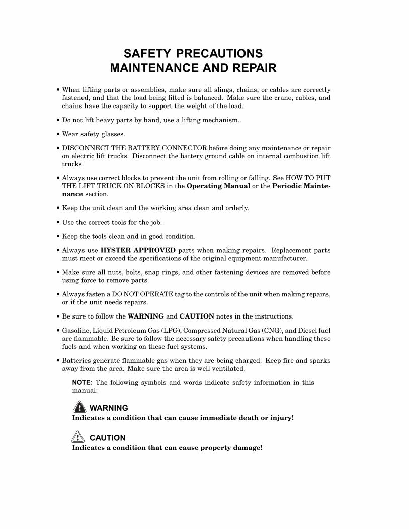
SAFETY PRECAUTIONSMAINTENANCE AND REPAIR
• When lifting parts or assemblies, make sure all slings, chains, or cables are correctlyfastened, and that the load being lifted is balanced. Make sure the crane, cables, andchains have the capacity to support the weight of the load.
• Do not lift heavy parts by hand, use a lifting mechanism.
• Wear safety glasses.
• DISCONNECT THE BATTERY CONNECTOR before doing any maintenance or repairon electric lift trucks. Disconnect the battery ground cable on internal combustion lifttrucks.
• Always use correct blocks to prevent the unit from rolling or falling. See HOW TO PUTTHE LIFT TRUCK ON BLOCKS in the Operating Manual or the Periodic Mainte-nance section.
• Keep the unit clean and the working area clean and orderly.
• Use the correct tools for the job.
• Keep the tools clean and in good condition.
• Always use HYSTER APPROVED parts when making repairs. Replacement partsmust meet or exceed the specifications of the original equipment manufacturer.
• Make sure all nuts, bolts, snap rings, and other fastening devices are removed beforeusing force to remove parts.
• Always fasten a DO NOT OPERATE tag to the controls of the unit when making repairs,or if the unit needs repairs.
• Be sure to follow the WARNING and CAUTION notes in the instructions.
• Gasoline, Liquid Petroleum Gas (LPG), Compressed Natural Gas (CNG), and Diesel fuelare flammable. Be sure to follow the necessary safety precautions when handling thesefuels and when working on these fuel systems.
• Batteries generate flammable gas when they are being charged. Keep fire and sparksaway from the area. Make sure the area is well ventilated.
NOTE: The following symbols and words indicate safety information in thismanual:
WARNINGIndicates a condition that can cause immediate death or injury!
CAUTIONIndicates a condition that can cause property damage!
Periodic Maintenance YardMaster® Table of Contents
TABLE OF CONTENTS
General ............................................................................................................................................................... 1Serial Number Data ...................................................................................................................................... 1How to Move Disabled YardMaster .............................................................................................................. 1
How to Tow YardMaster............................................................................................................................ 2How to Put YardMaster on Blocks................................................................................................................ 2
How to Raise Drive Tires .......................................................................................................................... 2How to Raise Steering Tires.......................................................................................................................... 2
Maintenance Schedule....................................................................................................................................... 3Daily Inspections ........................................................................................................................................... 3First Inspection After First 100 Hours of Operation................................................................................... 5Periodic Maintenance Schedule.................................................................................................................... 5Boom Maintenance ........................................................................................................................................ 7Spreader Maintenance .................................................................................................................................. 8PPM Spreader Maintenance ......................................................................................................................... 10
Maintenance Procedures Every 8 Hours or Daily............................................................................................ 12How to Make Checks With Engine Stopped................................................................................................. 12
Tires and Wheels ....................................................................................................................................... 12Safety Labels ............................................................................................................................................. 12Fuel, Oil, or Coolant Leaks Check............................................................................................................ 13Drive Belts ................................................................................................................................................. 13Battery ....................................................................................................................................................... 13Engine Oil .................................................................................................................................................. 14Drain Water From Fuel Filter .................................................................................................................. 14Hydraulic System...................................................................................................................................... 14Brake System Oil ...................................................................................................................................... 15Cooling System .......................................................................................................................................... 15Boom and Spreader ................................................................................................................................... 15Hook, Winch, and Boom (HR45H) ............................................................................................................ 15
How to Make Checks With Engine Running................................................................................................ 15Gauges, Indicator Lights, Horn, Circuit Breakers, and Relays.............................................................. 15Air Filter .................................................................................................................................................... 18Air Conditioning ........................................................................................................................................ 18Control Levers and Pedals........................................................................................................................ 18Electrical System....................................................................................................................................... 18Transmission Oil ....................................................................................................................................... 18Steering System ........................................................................................................................................ 19Service Brakes ........................................................................................................................................... 19Parking Brake ........................................................................................................................................... 19Engine Oil .................................................................................................................................................. 19Cooling System .......................................................................................................................................... 19Hydraulic System...................................................................................................................................... 19Boom and Spreader Operation ................................................................................................................. 19
Maintenance Procedures Every 50 Hours or Weekly....................................................................................... 20Boom............................................................................................................................................................... 20PPM Spreader................................................................................................................................................ 20
Rotator and Extension Transmissions ..................................................................................................... 20Rotator Motor ............................................................................................................................................ 20Rotator Assembly ...................................................................................................................................... 20Twist Locks ................................................................................................................................................ 21Wear Pads (Extension Beam) ................................................................................................................... 21Sideshift Cylinders .................................................................................................................................... 21
©2005 HYSTER COMPANY i
Table of Contents Periodic Maintenance YardMaster®
TABLE OF CONTENTS (Continued)
Maintenance Procedures Every 250 Hours or 6 Weeks ................................................................................... 21Engine Oil and Filter..................................................................................................................................... 21Fuel Filter/Water Separator.......................................................................................................................... 21Drive Belts ..................................................................................................................................................... 21Steering Axle.................................................................................................................................................. 21Battery ........................................................................................................................................................... 21Wheel Nuts..................................................................................................................................................... 21Winch Oil Level.............................................................................................................................................. 21Steering Axle Tie Rods and King Pins.......................................................................................................... 22Drive Shaft Joints.......................................................................................................................................... 22General Lubrication ...................................................................................................................................... 22ELME Spreader ............................................................................................................................................. 22
Rotator and Extension Transmission....................................................................................................... 22Rotator Assembly ...................................................................................................................................... 22Twist Locks ................................................................................................................................................ 22
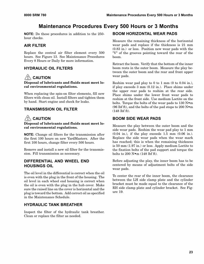
Maintenance Procedures Every 500 Hours or 3 Months ................................................................................. 23Air Filter ........................................................................................................................................................ 23Hydraulic Oil Filters ..................................................................................................................................... 23Transmission Oil Filter ................................................................................................................................. 23Differential and Wheel End Housings Oil.................................................................................................... 23Hydraulic Tank Breather .............................................................................................................................. 23Boom Horizontal Wear Pads ......................................................................................................................... 23Boom Side Wear Pads.................................................................................................................................... 23Sideshift Cylinder.......................................................................................................................................... 24Stop Cylinders (ELME Option)..................................................................................................................... 24ELME Sideshift Wear Pads .......................................................................................................................... 24Wear Pads (Extension Beams) ...................................................................................................................... 24
Maintenance Procedures Every 1000 Hours or 6 Months ............................................................................... 25Coolant Filter................................................................................................................................................. 25Hydraulic Accumulators................................................................................................................................ 25
Brake Accumulator ................................................................................................................................... 25Transmission Oil............................................................................................................................................ 25Disc Brake...................................................................................................................................................... 25
Inspect........................................................................................................................................................ 26Brake System Oil and Filter ......................................................................................................................... 26Air Filter Primary Element .......................................................................................................................... 26Hydraulic Tank Breather .............................................................................................................................. 26PPM Spreader................................................................................................................................................ 26
Extension Beam Horizontal Pads............................................................................................................. 26Extension Beam Side Wear Pads ............................................................................................................. 26Ring Gear Fixation Bolts .......................................................................................................................... 26
ELME Spreader ............................................................................................................................................. 27Wear Pads (Extension Cylinder) .............................................................................................................. 27
Winch Oil........................................................................................................................................................ 27Pedals, Levers, Hinges, and Seat Rails (General Lubrication)................................................................... 27
Maintenance Procedures Every 2000 Hours or Yearly .................................................................................... 27Engine Valve Adjustment.............................................................................................................................. 27Hydraulic Relief Pressures ........................................................................................................................... 27Counterweight Fixation ................................................................................................................................ 27Load Sensing System .................................................................................................................................... 27Door and Window Seals................................................................................................................................. 27
ii
Periodic Maintenance YardMaster® Table of Contents
TABLE OF CONTENTS (Continued)
Drive Axle and Differential Oil..................................................................................................................... 27Hydraulic Oil ................................................................................................................................................. 27
Change Hydraulic Oil ............................................................................................................................... 27Steer Wheel Hub Bearing Cavity ................................................................................................................. 28Brake System Oil and Filter ......................................................................................................................... 28Rotor and Extension Transmission Fixation Bolts ...................................................................................... 28Rotator and Extension Transmission Oil ..................................................................................................... 28
Maintenance Procedures Every 6000 Hours or 2 Years................................................................................... 28Engine Coolant .............................................................................................................................................. 28Vibration Damper .......................................................................................................................................... 28Twist Locks .................................................................................................................................................... 28
Maintenance Procedures Every 8000 Hours .................................................................................................... 29PPM Spreader................................................................................................................................................ 29
Wheel and Tire Replacement ............................................................................................................................ 29Wheels, Remove ............................................................................................................................................. 29Remove Tire From Wheel.............................................................................................................................. 30Install Tire on Wheel ..................................................................................................................................... 31Install Wheel in Tire...................................................................................................................................... 31Add Air to Tires ............................................................................................................................................. 32Wheels, Install ............................................................................................................................................... 33
General Maintenance ........................................................................................................................................ 33Spreader ......................................................................................................................................................... 33
Twist Locks ................................................................................................................................................ 33Rotator Assembly ...................................................................................................................................... 33
How to Store YardMaster.............................................................................................................................. 33Short-Term Storage ................................................................................................................................... 33Long-Term Storage.................................................................................................................................... 34
How to Move YardMaster On Transport ...................................................................................................... 34Loading ...................................................................................................................................................... 34Unloading .................................................................................................................................................. 35
Preparation for Use ....................................................................................................................................... 35Preparation After Transport..................................................................................................................... 35Preparation After Storage ........................................................................................................................ 35
This section is for the following models:
HR45-25, HR45-27, HR45-31, HR45-40S, HR45-36L, HR45-40LS,HR45-45LSX, HR45H [A227, B227]
iii

"THEQUALITYKEEPERS"
HYSTERAPPROVEDPARTS
8000 SRM 780 General
GeneralThis section contains a Maintenance Schedule andthe instructions for maintenance and inspection.
The Maintenance Schedule has time intervals forinspection, lubrication, and maintenance for yourYardMaster. The recommendation for the time in-tervals are for 8 hours of operation per day. The timeintervals must be decreased from the recommenda-tions in the Maintenance Schedule for the followingconditions:• If the YardMaster is used more than 8 hours per
day• If the YardMaster must work in dirty operating
conditions
Your dealer for Hyster YardMasters has the equip-ment and trained personnel to do a complete programof inspection, lubrication, and maintenance. A regu-lar program of inspection, lubrication, and mainte-nance will help your YardMaster give more efficientperformance and operate for a longer period of time.
WARNINGDo not make repairs or adjustments unless youhave both authorization and training. Repairsand adjustments made on a YardMaster bypeople without authorization and training canmake a dangerous operating condition.
Do not operate a YardMaster that needs re-pairs. Report the need for repairs immediately.If repair is necessary, put a DO NOT OPERATEtag in the operator’s area. Remove the keyfrom the key switch.
Some users have service personnel and equipmentto do the inspection, lubrication, and maintenanceshown in the Maintenance Schedule. Service Man-uals are available from your dealer for Hyster Yard-Masters to help users who do their own maintenance.
SERIAL NUMBER DATA
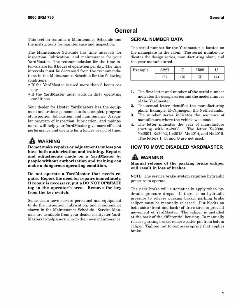
The serial number for the Yardmaster is located onthe nameplate in the cabin. The serial number in-dicates the design series, manufacturing plant, andthe year manufactured.
A227 E 1509 UExample:
(1) (2) (3) (4)
1. The first letter and number of the serial numberindicates the design series and the model numberof the Yardmaster.
2. The second letter identifies the manufacturingplant. Example: E=Nijmegen, the Netherlands.
3. The number series indicates the sequence ofmanufacture where the vehicle was made.
4. The letter indicates the year of manufacturestarting with A=2003. The letter X=2000,Y=2001, Z=2002, L=2013, M=2014, and N=2015.(The letters I, O, and Q are not used.)
HOW TO MOVE DISABLED YARDMASTER
WARNINGManual release of the parking brake caliperwill result in loss of brakes.
NOTE: The service brake system requires hydraulicpressure to operate.
The park brake will automatically apply when hy-draulic pressure drops. If there is no hydraulicpressure to release parking brake, parking brakecaliper must be manually released. Put blocks onboth sides (front and back) of drive tires to preventmovement of YardMaster. The caliper is installedat the back of the differential housing. To manuallyrelease parking brake, remove cotter pin from bolt incaliper. Tighten nut to compress spring that appliesbrake.
1
General 8000 SRM 780
How to Tow YardMaster
WARNINGDo not tow a YardMaster if a load is attached.
Use extra caution when moving a YardMasterif any of the following conditions exist:• Brakes do not operate correctly.• Steering does not operate correctly.• Tires are damaged.• Traction conditions are bad.
If the engine cannot run, there is no powerassist available for the steering and servicebrakes. This can make the control of the Yard-Master difficult. Poor traction can cause thedisabled YardMaster or towing vehicle to slide.
Manual release of the parking brake caliperwill result in loss of brakes.
1. The towed YardMaster must have an operator.
2. Tow YardMaster slowly.
3. Tow YardMaster from lifting points of counter-weight attached to frame.
4. If another YardMaster is used to tow disabledYardMaster, that YardMaster must have anequal or larger capacity than disabled YardMas-ter.
HOW TO PUT YARDMASTER ON BLOCKS
How to Raise Drive Tires
WARNINGThe YardMaster must be put on blocks forsome types of maintenance and repair. Thesurface must be solid, even, and level whenthe YardMaster is put on blocks. Make sureany blocks used to support the YardMaster aresolid, one-piece units. Do not use componentlifting points on the boom or frame to lift theYardMaster.
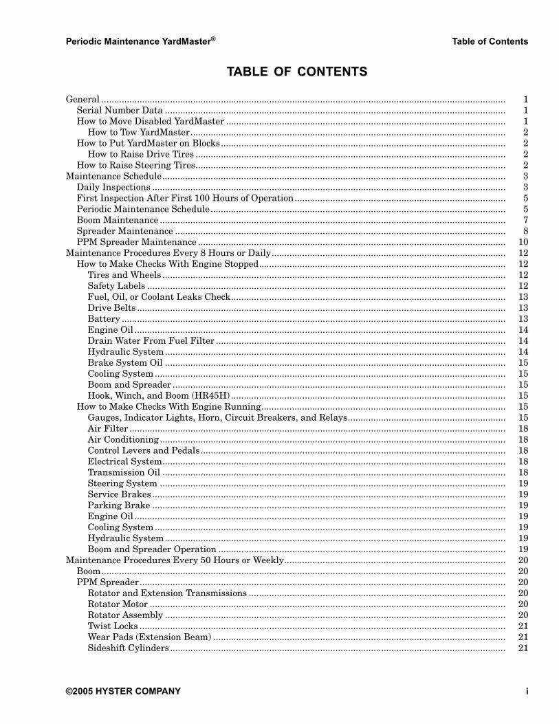
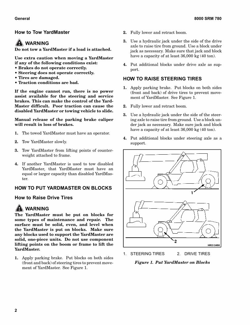
1. Apply parking brake. Put blocks on both sides(front and back) of steering tires to prevent move-ment of YardMaster. See Figure 1.
2. Fully lower and retract boom.
3. Use a hydraulic jack under the side of the driveaxle to raise tire from ground. Use a block underjack as necessary. Make sure that jack and blockhave a capacity of at least 36,000 kg (40 ton).
4. Put additional blocks under drive axle as sup-port.
HOW TO RAISE STEERING TIRES
1. Apply parking brake. Put blocks on both sides(front and back) of drive tires to prevent move-ment of YardMaster. See Figure 1.
2. Fully lower and retract boom.
3. Use a hydraulic jack under the side of the steer-ing axle to raise tire from ground. Use a block un-der jack as necessary. Make sure jack and blockhave a capacity of at least 36,000 kg (40 ton).
4. Put additional blocks under steering axle as asupport.
1. STEERING TIRES 2. DRIVE TIRES
Figure 1. Put YardMaster on Blocks
2
8000 SRM 780 Maintenance Schedule
Maintenance ScheduleDAILY INSPECTIONS
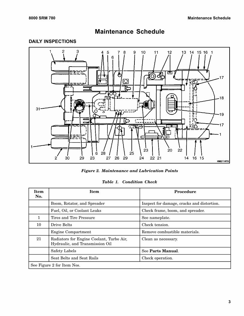
Figure 2. Maintenance and Lubrication Points
Table 1. Condition Check
ItemNo.
Item Procedure
Boom, Rotator, and Spreader Inspect for damage, cracks and distortion.
Fuel, Oil, or Coolant Leaks Check frame, boom, and spreader.
1 Tires and Tire Pressure See nameplate.
10 Drive Belts Check tension.
Engine Compartment Remove combustible materials.
21 Radiators for Engine Coolant, Turbo Air,Hydraulic, and Transmission Oil
Clean as necessary.
Safety Labels See Parts Manual.
Seat Belts and Seat Rails Check operation.
See Figure 2 for Item Nos.
3
Maintenance Schedule 8000 SRM 780
Table 2. Fluid Level Check
ItemNo.
Item Procedure
12 Hydraulic System Oil J20C or equivalent
13 Brake System Oil (UntilA227J 01587, B227J 01501,01503, and 01504)
SAE 10W, API CC, or CC/SE with 3 to 6% lubrisol
13 Brake System Oil (Startingwith A227J 01588, B227J01502, and 01505)
Donax TD SAE 10W
7 Fuel Diesel No. 2 (520 liter)
22 Coolant 50% Ethylene glycol, 50% water
4 Battery Electrolyte Distilled water
28 Engine Oil See Maintenance Procedures Every 8 Hours or Daily and EngineOil.
8 Water Separator Drain water.
Windshield Washer Fluid Add as necessary.
See Figure 2 for Item Nos.
Table 3. Checks With Engine Running
ItemNo.
Item Procedure
Air Conditioning Operate at least once every 15 days for 10 minutes.
Horn, Gauges, Lights,Alarms, Mirrors, and ControlSystem
Check operation.
Control Levers and Pedals Check operation.
Boom, Rotator, Spreader,Signal From Spreader, andControl System
Check operation.
Steering System Check operation.
Service Brakes and ParkingBrake
Check operation.
Transmission Check operation.
5 Transmission Oil Level Add if necessary, J20C or equivalent.
29 Air Filter Clean or replace elements when indicator light is ON.
24 Hydraulic Oil Filter Clean or replace when indicator light is ON.
See Figure 2 for Item Nos.
4
8000 SRM 780 Maintenance Schedule
FIRST INSPECTION AFTER FIRST 100HOURS OF OPERATION
Table 4. Initial 100-Hour Inspection
ItemNo. Item Procedure Quantity Procedure or
Specification
31 Drive Axle, Differential Oil Change 66 liter (69.7 qt) SAE 80W-90
27 Engine Oil Filter Change 1 See Parts Manual
6 Transmission Oil Filter Change 1 See Parts Manual
24 Hydraulic System Oil Filter Clean 1 See Parts Manual
25 Brake System Oil Filter Change 1 See Parts Manual
26 Coolant Filter Change 1 See Parts Manual
11 Hydraulic Oil Return Screen Clean 1
See Figure 2 for Item Nos.
PERIODIC MAINTENANCE SCHEDULE
Table 5. Inspect and Adjust
ItemNo.
Item Interval Procedure
3 Wheel Nuts 250 hr/1 mo Check torque.380 N•m (280 lbf ft)
10 Drive Belts 250 hr/1 mo Check tension.
31 Drive Axle and Differential Oil 500 hr/3 mo Check level. SAE 80W-90
12 Hydraulic Tank Breather 500 hr/3 mo Clean or replace if necessary.
20 Accumulator 1000 hr/6 mo See Accumulator 1800 SRM 1036
30 Parking Brake 1000 hr/6 mo Check wear.
9 Engine Valve Adjustment 2000 hr/1 yr
9 Inlet (cold)Exhaust (cold)
2000 hr/1 yr 0.36 mm (0.014 in.)0.68 mm (0.027 in.)
19 Hydraulic Relief Pressures 2000 hr/1 yr Check and adjust if necessary.
14 Counterweight Fasteners 2000 hr/1 yr Check torque.900 N•m (665 lbf ft)
Load Sensing System 2000 hr/1 yr Check calibration, see publication1495851.
11 Hydraulic Oil Return Screen 2000 hr/1 yr Clean or replace.
10 Vibration Damper 4000 hr/2 yr Inspect for wear.
See Figure 2 for Item Nos.
5
Maintenance Schedule 8000 SRM 780
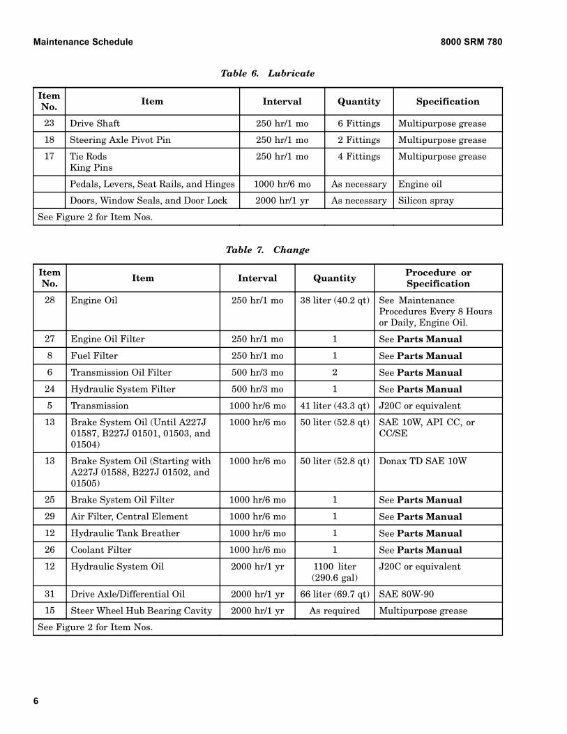
Table 6. Lubricate
ItemNo. Item Interval Quantity Specification
23 Drive Shaft 250 hr/1 mo 6 Fittings Multipurpose grease
18 Steering Axle Pivot Pin 250 hr/1 mo 2 Fittings Multipurpose grease
17 Tie RodsKing Pins
250 hr/1 mo 4 Fittings Multipurpose grease
Pedals, Levers, Seat Rails, and Hinges 1000 hr/6 mo As necessary Engine oil
Doors, Window Seals, and Door Lock 2000 hr/1 yr As necessary Silicon spray
See Figure 2 for Item Nos.
Table 7. Change
ItemNo. Item Interval Quantity Procedure or
Specification
28 Engine Oil 250 hr/1 mo 38 liter (40.2 qt) See MaintenanceProcedures Every 8 Hoursor Daily, Engine Oil.
27 Engine Oil Filter 250 hr/1 mo 1 See Parts Manual
8 Fuel Filter 250 hr/1 mo 1 See Parts Manual
6 Transmission Oil Filter 500 hr/3 mo 2 See Parts Manual
24 Hydraulic System Filter 500 hr/3 mo 1 See Parts Manual
5 Transmission 1000 hr/6 mo 41 liter (43.3 qt) J20C or equivalent
13 Brake System Oil (Until A227J01587, B227J 01501, 01503, and01504)
1000 hr/6 mo 50 liter (52.8 qt) SAE 10W, API CC, orCC/SE
13 Brake System Oil (Starting withA227J 01588, B227J 01502, and01505)
1000 hr/6 mo 50 liter (52.8 qt) Donax TD SAE 10W
25 Brake System Oil Filter 1000 hr/6 mo 1 See Parts Manual
29 Air Filter, Central Element 1000 hr/6 mo 1 See Parts Manual
12 Hydraulic Tank Breather 1000 hr/6 mo 1 See Parts Manual
26 Coolant Filter 1000 hr/6 mo 1 See Parts Manual
12 Hydraulic System Oil 2000 hr/1 yr 1100 liter(290.6 gal)
J20C or equivalent
31 Drive Axle/Differential Oil 2000 hr/1 yr 66 liter (69.7 qt) SAE 80W-90
15 Steer Wheel Hub Bearing Cavity 2000 hr/1 yr As required Multipurpose grease
See Figure 2 for Item Nos.
6
8000 SRM 780 Maintenance Schedule
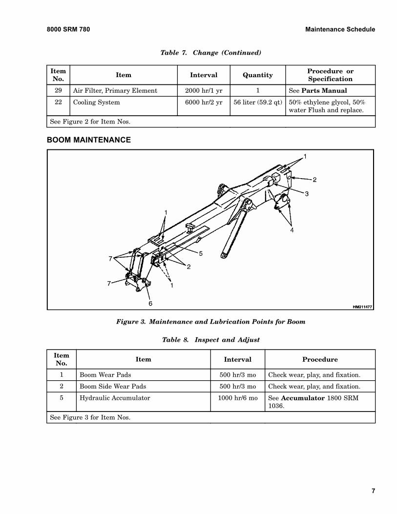
Table 7. Change (Continued)
ItemNo. Item Interval Quantity Procedure or
Specification
29 Air Filter, Primary Element 2000 hr/1 yr 1 See Parts Manual
22 Cooling System 6000 hr/2 yr 56 liter (59.2 qt) 50% ethylene glycol, 50%water Flush and replace.
See Figure 2 for Item Nos.
BOOM MAINTENANCE
Figure 3. Maintenance and Lubrication Points for Boom
Table 8. Inspect and Adjust
ItemNo. Item Interval Procedure
1 Boom Wear Pads 500 hr/3 mo Check wear, play, and fixation.
2 Boom Side Wear Pads 500 hr/3 mo Check wear, play, and fixation.
5 Hydraulic Accumulator 1000 hr/6 mo See Accumulator 1800 SRM1036.
See Figure 3 for Item Nos.
7
Maintenance Schedule 8000 SRM 780
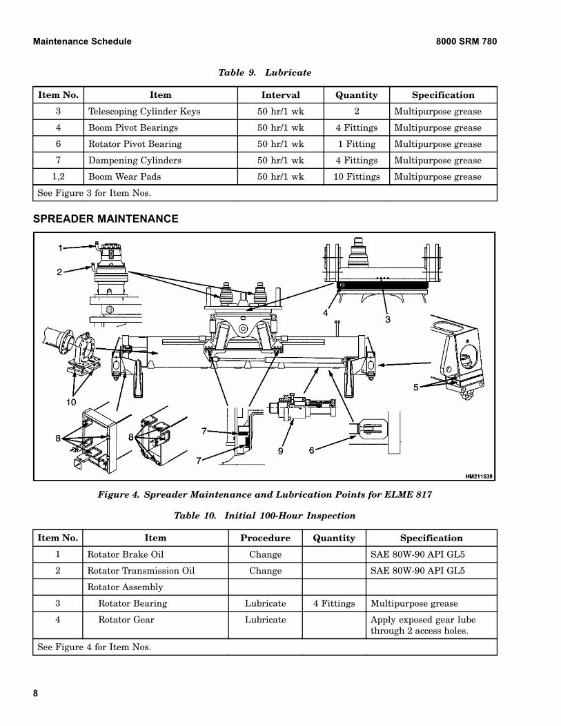
Table 9. Lubricate
Item No. Item Interval Quantity Specification
3 Telescoping Cylinder Keys 50 hr/1 wk 2 Multipurpose grease
4 Boom Pivot Bearings 50 hr/1 wk 4 Fittings Multipurpose grease
6 Rotator Pivot Bearing 50 hr/1 wk 1 Fitting Multipurpose grease
7 Dampening Cylinders 50 hr/1 wk 4 Fittings Multipurpose grease
1,2 Boom Wear Pads 50 hr/1 wk 10 Fittings Multipurpose grease
See Figure 3 for Item Nos.
SPREADER MAINTENANCE
Figure 4. Spreader Maintenance and Lubrication Points for ELME 817
Table 10. Initial 100-Hour Inspection
Item No. Item Procedure Quantity Specification
1 Rotator Brake Oil Change SAE 80W-90 API GL5
2 Rotator Transmission Oil Change SAE 80W-90 API GL5
Rotator Assembly
3 Rotator Bearing Lubricate 4 Fittings Multipurpose grease
4 Rotator Gear Lubricate Apply exposed gear lubethrough 2 access holes.
See Figure 4 for Item Nos.
8
8000 SRM 780 Maintenance Schedule
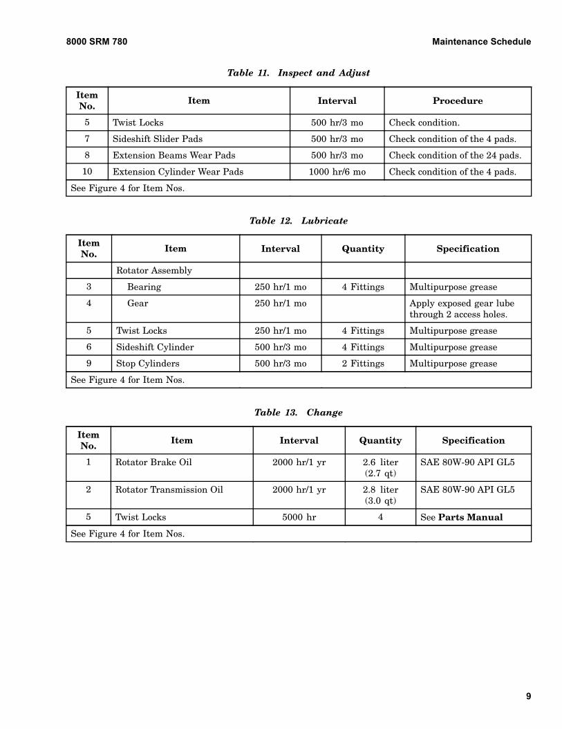
Table 11. Inspect and Adjust
ItemNo. Item Interval Procedure
5 Twist Locks 500 hr/3 mo Check condition.
7 Sideshift Slider Pads 500 hr/3 mo Check condition of the 4 pads.
8 Extension Beams Wear Pads 500 hr/3 mo Check condition of the 24 pads.
10 Extension Cylinder Wear Pads 1000 hr/6 mo Check condition of the 4 pads.
See Figure 4 for Item Nos.
Table 12. Lubricate
ItemNo. Item Interval Quantity Specification
Rotator Assembly
3 Bearing 250 hr/1 mo 4 Fittings Multipurpose grease
4 Gear 250 hr/1 mo Apply exposed gear lubethrough 2 access holes.
5 Twist Locks 250 hr/1 mo 4 Fittings Multipurpose grease
6 Sideshift Cylinder 500 hr/3 mo 4 Fittings Multipurpose grease
9 Stop Cylinders 500 hr/3 mo 2 Fittings Multipurpose grease
See Figure 4 for Item Nos.
Table 13. Change
ItemNo. Item Interval Quantity Specification
1 Rotator Brake Oil 2000 hr/1 yr 2.6 liter(2.7 qt)
SAE 80W-90 API GL5
2 Rotator Transmission Oil 2000 hr/1 yr 2.8 liter(3.0 qt)
SAE 80W-90 API GL5
5 Twist Locks 5000 hr 4 See Parts Manual
See Figure 4 for Item Nos.
9
Maintenance Schedule 8000 SRM 780
PPM SPREADER MAINTENANCE
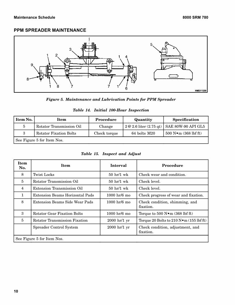
Figure 5. Maintenance and Lubrication Points for PPM Spreader
Table 14. Initial 100-Hour Inspection
Item No. Item Procedure Quantity Specification
5 Rotator Transmission Oil Change 2 @ 2.6 liter (2.75 qt) SAE 80W-90 API GL5
3 Rotator Fixation Bolts Check torque 64 bolts M20 500 N•m (368 lbf ft)
See Figure 5 for Item Nos.
Table 15. Inspect and Adjust
ItemNo. Item Interval Procedure
8 Twist Locks 50 hr/1 wk Check wear and condition.
5 Rotator Transmission Oil 50 hr/1 wk Check level.
4 Extension Transmission Oil 50 hr/1 wk Check level.
1 Extension Beams Horizontal Pads 1000 hr/6 mo Check progress of wear and fixation.
8 Extension Beams Side Wear Pads 1000 hr/6 mo Check condition, shimming, andfixation.
3 Rotator Gear Fixation Bolts 1000 hr/6 mo Torque to 500 N•m (368 lbf ft)
5 Rotator Transmission Fixation 2000 hr/1 yr Torque 20 Bolts to 210 N•m (155 lbf ft)
Spreader Control System 2000 hr/1 yr Check condition, adjustment, andfixation.
See Figure 5 for Item Nos.
10
8000 SRM 780 Maintenance Schedule
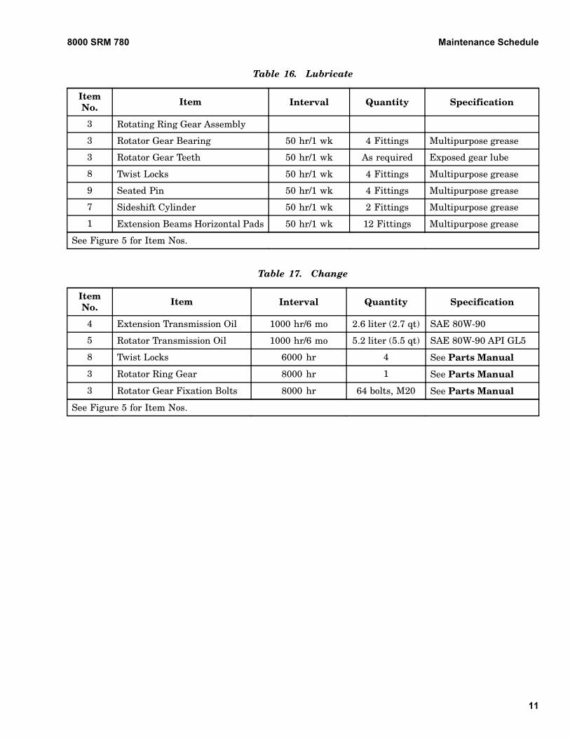
Table 16. Lubricate
ItemNo. Item Interval Quantity Specification
3 Rotating Ring Gear Assembly
3 Rotator Gear Bearing 50 hr/1 wk 4 Fittings Multipurpose grease
3 Rotator Gear Teeth 50 hr/1 wk As required Exposed gear lube
8 Twist Locks 50 hr/1 wk 4 Fittings Multipurpose grease
9 Seated Pin 50 hr/1 wk 4 Fittings Multipurpose grease
7 Sideshift Cylinder 50 hr/1 wk 2 Fittings Multipurpose grease
1 Extension Beams Horizontal Pads 50 hr/1 wk 12 Fittings Multipurpose grease
See Figure 5 for Item Nos.
Table 17. Change
ItemNo. Item Interval Quantity Specification
4 Extension Transmission Oil 1000 hr/6 mo 2.6 liter (2.7 qt) SAE 80W-90
5 Rotator Transmission Oil 1000 hr/6 mo 5.2 liter (5.5 qt) SAE 80W-90 API GL5
8 Twist Locks 6000 hr 4 See Parts Manual
3 Rotator Ring Gear 8000 hr 1 See Parts Manual
3 Rotator Gear Fixation Bolts 8000 hr 64 bolts, M20 See Parts Manual
See Figure 5 for Item Nos.
11
Maintenance Procedures Every 8 Hours or Daily 8000 SRM 780
Maintenance Procedures Every 8 Hours or DailyHOW TO MAKE CHECKS WITH ENGINESTOPPED
WARNINGDo not operate a YardMaster that needs re-pairs. Report the need for repairs immediately.If repair is necessary, put a DO NOT OPERATEtag in the operator’s area. Remove the keyfrom the key switch.
Put YardMaster on level surface. Fully lower and re-tract boom, stop engine, and apply parking brake. Doall checks outside of engine compartment first. Openhood and check for abnormal leaks and conditions.Clean any oil or fuel spills. Make sure dirt and othermaterials are removed from engine compartment.
Tires and Wheels
WARNINGRemove all of the air from the tires before thetires are removed from the YardMaster.
Air pressure in tires can cause tire and wheelparts to explode. The explosion of wheel partscan cause serious injury or death.
If the air pressure is less than 80% of the cor-rect air pressure, the tire must be removed be-fore air is added. Put the tire in a safety cagewhen adding air pressure to the tire. Followthe procedures described in Add Air to Tires.
When air is added to the tires, use a remote airchuck. The person adding air must stand awayand to the side and not in front of the tire.
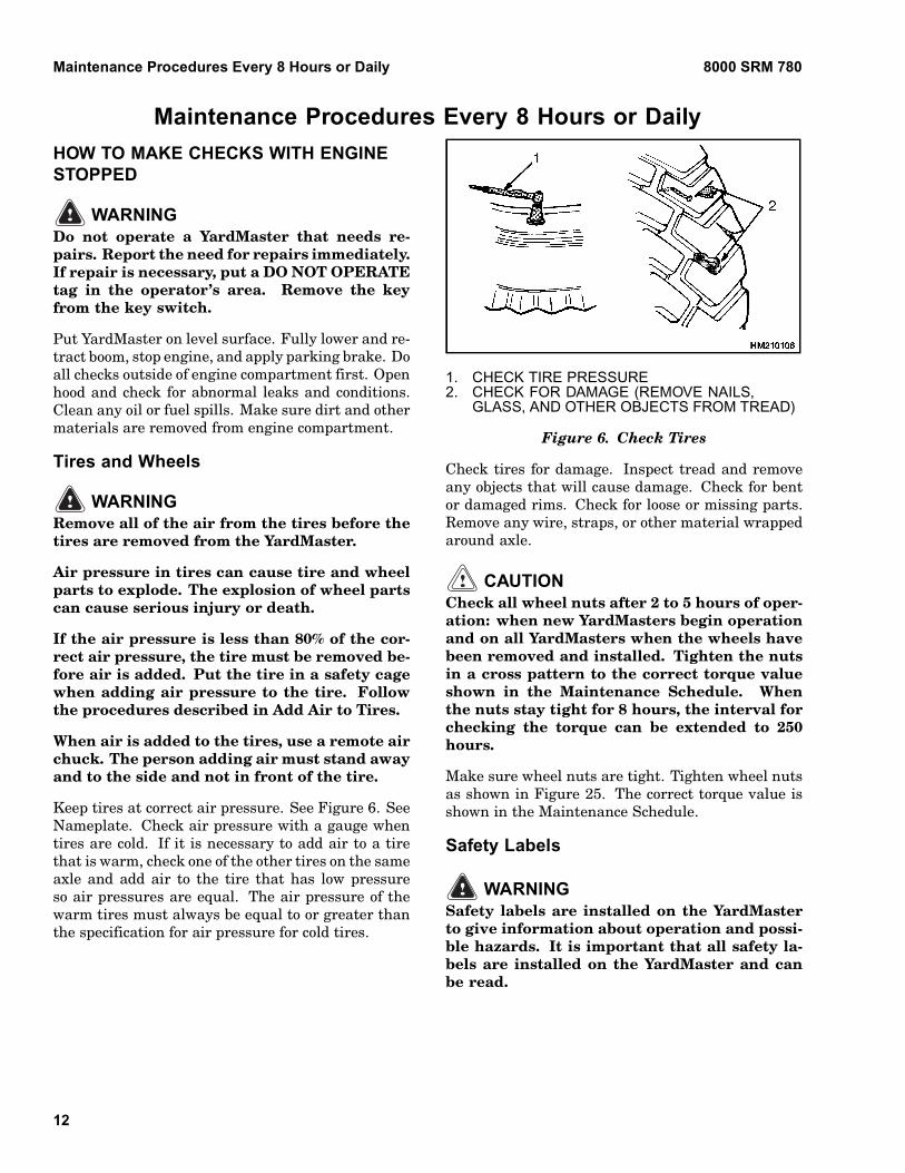
Keep tires at correct air pressure. See Figure 6. SeeNameplate. Check air pressure with a gauge whentires are cold. If it is necessary to add air to a tirethat is warm, check one of the other tires on the sameaxle and add air to the tire that has low pressureso air pressures are equal. The air pressure of thewarm tires must always be equal to or greater thanthe specification for air pressure for cold tires.
1. CHECK TIRE PRESSURE2. CHECK FOR DAMAGE (REMOVE NAILS,
GLASS, AND OTHER OBJECTS FROM TREAD)
Figure 6. Check Tires
Check tires for damage. Inspect tread and removeany objects that will cause damage. Check for bentor damaged rims. Check for loose or missing parts.Remove any wire, straps, or other material wrappedaround axle.
CAUTIONCheck all wheel nuts after 2 to 5 hours of oper-ation: when new YardMasters begin operationand on all YardMasters when the wheels havebeen removed and installed. Tighten the nutsin a cross pattern to the correct torque valueshown in the Maintenance Schedule. Whenthe nuts stay tight for 8 hours, the interval forchecking the torque can be extended to 250hours.
Make sure wheel nuts are tight. Tighten wheel nutsas shown in Figure 25. The correct torque value isshown in the Maintenance Schedule.
Safety Labels
WARNINGSafety labels are installed on the YardMasterto give information about operation and possi-ble hazards. It is important that all safety la-bels are installed on the YardMaster and canbe read.
12

8000 SRM 780 Maintenance Procedures Every 8 Hours or Daily
Check that all safety labels are installed in correctlocations on YardMaster. See the Parts Manual forthe correct locations of the safety labels.
If new labels must be installed, use the following pro-cedures:
WARNINGCleaning solvents can be flammable and toxicand can cause skin irritation. When usingcleaning solvents, always follow the recom-mendations of the manufacturer.
1. Make sure surface is dry and has no oil or grease.Do not use solvent on new paint. Clean surfaceof old paint with cleaning solvent.
2. Remove paper from back of label. Do not touchadhesive surface.
3. Carefully hold label in correct position above sur-face. The label cannot be moved after it touchesthe surface. Put label on the surface. Make sureall air is removed from under label and cornersand edges are tight.
Fuel, Oil, or Coolant Leaks Check
WARNINGAll fuels are very flammable and can burn orcause an explosion. Do not use an open flameto check the fuel level or to check for leaks inthe fuel system. If there is a leak in the fuel sys-tem, extra care must be used during the repair.Do not operate the YardMaster until a leak isrepaired.
Make a visual check for leaks on and under YardMas-ter. If possible, find and repair leak at the source.Leaks can indicate a need for repair of damaged orworn components.
Check fuel system for leaks and condition of parts.When fuel is added to YardMaster, see How To AddFuel to YardMaster procedures in OperatingManual.
Also check condition of radiator or heater hoses. Re-place soft or cracked hoses.
Drive Belts
Make sure key is in OFF position and engine isstopped. Check drive belt for wear and damage.See Figure 7. Small cracks that run across belt are
acceptable. A drive belt with cracks that run thelength of the belt or a belt with missing pieces is notacceptable.
Check drive belt for correct tension.
1. ACCEPTABLE CRACKS2. NOT ACCEPTABLE CRACKS AND DAMAGE
Figure 7. Drive Belt
Battery
A check of the battery electrolyte level is normallyrequired only every 250 hours of operation. Heavyduty or high temperature operations will requiremore frequent checks. It is not necessary to checkthe electrolyte level on a maintenance-free battery.A low electrolyte level can cause the discharge in-dicator light to come on or cause battery damageduring YardMaster operation.
WARNINGThe acid in the electrolyte can cause injury.If the electrolyte is spilled, use water to flushthe area. Use a solution of sodium bicarbon-ate (soda) to make the acid neutral. Acid in theeyes must be flushed with water immediately.Wear eye protection.
Batteries generate explosive fumes. Keep thevents in the caps clean. Keep sparks or openflame away from the battery area. Do notmake sparks from the battery connections.Disconnect the battery ground cable whendoing maintenance.
Keep battery and cable terminals clean. Check elec-trolyte level (unless maintenance-free battery). Keepelectrolyte level above separators and plates. Usedistilled water. Do not fill battery more than to bot-tom of internal filler neck.
13
Maintenance Procedures Every 8 Hours or Daily 8000 SRM 780
If the battery becomes discharged and requires abooster battery to start engine, follow these proce-dures carefully when connecting jumper cables:
1. Always connect positive jumper cable to positiveterminal of discharged battery and negativejumper cable to negative terminal.
2. Always connect jumper cable that is the groundcable last.
CAUTIONDisposal of batteries must meet local environ-mental regulations.
3. Always connect jumper cables to discharged bat-tery before connecting them to booster battery.
Engine Oil
Check oil level in engine daily. After engine hasstopped, wait one minute before checking oil level.Keep oil at correct level as indicated on dipstick. Usecorrect oil as indicated below:
API CE/SF or CE/SGSAE 10W-30 25 to 25 C ( 13 to 77 F)SAE 15W-40 15 to 35 C (5 to 95 F)SAE 20W-40 5 to 45 C (23 to 113 F)
Drain Water From Fuel Filter
CAUTIONDisposal of lubricants and fluids must meet lo-cal environmental regulations.
Open drain valve on bottom of fuel filter. Drain somefuel (and any water) into a container until clean fuelflows from filter. Close drain valve.
Hydraulic System
WARNINGAt operating temperature the hydraulic oil isHOT. Do not permit the hot oil to touch the skinand cause a burn.
CAUTIONDo not permit dirt to enter the hydraulic sys-tem when the oil level is checked or the filteris changed.
Never operate the hydraulic pump without oilin the hydraulic system. The operation of thehydraulic pump without oil will damage thepump.
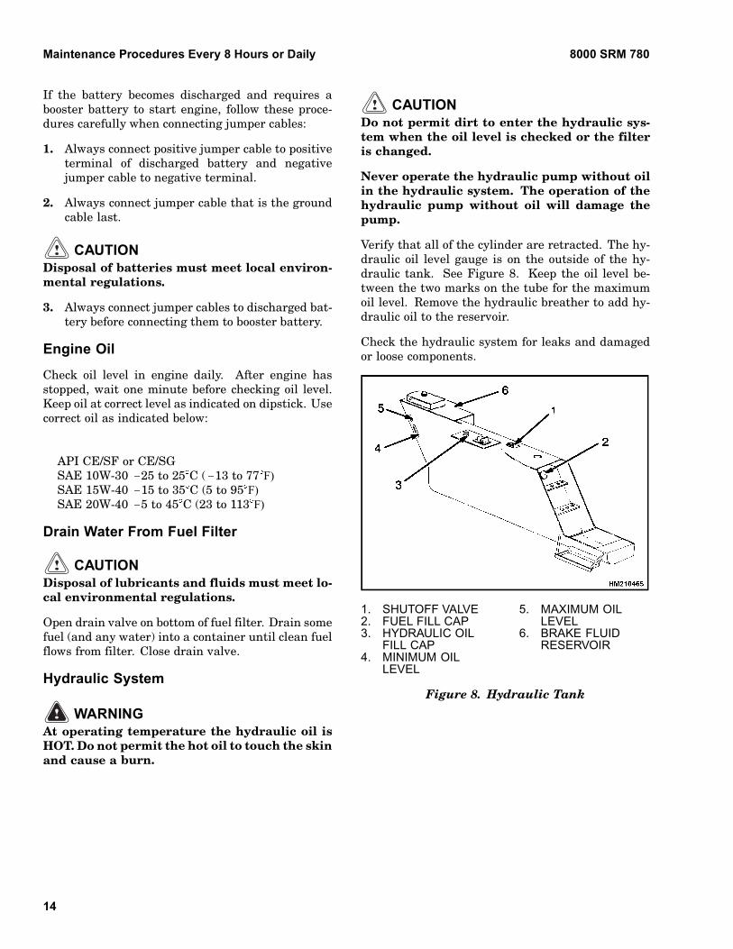
Verify that all of the cylinder are retracted. The hy-draulic oil level gauge is on the outside of the hy-draulic tank. See Figure 8. Keep the oil level be-tween the two marks on the tube for the maximumoil level. Remove the hydraulic breather to add hy-draulic oil to the reservoir.
Check the hydraulic system for leaks and damagedor loose components.
1. SHUTOFF VALVE2. FUEL FILL CAP3. HYDRAULIC OIL
FILL CAP4. MINIMUM OIL
LEVEL
5. MAXIMUM OILLEVEL
6. BRAKE FLUIDRESERVOIR
Figure 8. Hydraulic Tank
14
8000 SRM 780 Maintenance Procedures Every 8 Hours or Daily
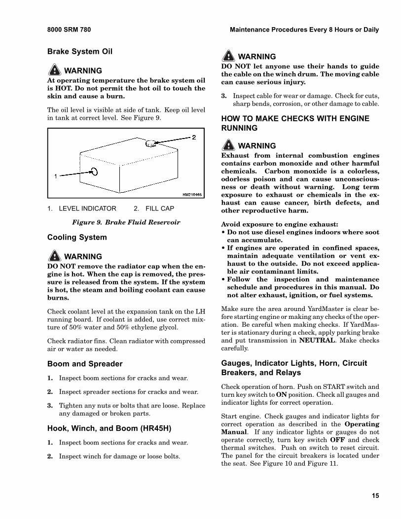
Brake System Oil
WARNINGAt operating temperature the brake system oilis HOT. Do not permit the hot oil to touch theskin and cause a burn.
The oil level is visible at side of tank. Keep oil levelin tank at correct level. See Figure 9.
1. LEVEL INDICATOR 2. FILL CAP
Figure 9. Brake Fluid Reservoir
Cooling System
WARNINGDO NOT remove the radiator cap when the en-gine is hot. When the cap is removed, the pres-sure is released from the system. If the systemis hot, the steam and boiling coolant can causeburns.
Check coolant level at the expansion tank on the LHrunning board. If coolant is added, use correct mix-ture of 50% water and 50% ethylene glycol.
Check radiator fins. Clean radiator with compressedair or water as needed.
Boom and Spreader
1. Inspect boom sections for cracks and wear.
2. Inspect spreader sections for cracks and wear.
3. Tighten any nuts or bolts that are loose. Replaceany damaged or broken parts.
Hook, Winch, and Boom (HR45H)
1. Inspect boom sections for cracks and wear.
2. Inspect winch for damage or loose bolts.
WARNINGDO NOT let anyone use their hands to guidethe cable on the winch drum. The moving cablecan cause serious injury.
3. Inspect cable for wear or damage. Check for cuts,sharp bends, corrosion, or other damage to cable.
HOW TO MAKE CHECKS WITH ENGINERUNNING
WARNINGExhaust from internal combustion enginescontains carbon monoxide and other harmfulchemicals. Carbon monoxide is a colorless,odorless poison and can cause unconscious-ness or death without warning. Long termexposure to exhaust or chemicals in the ex-haust can cause cancer, birth defects, andother reproductive harm.
Avoid exposure to engine exhaust:• Do not use diesel engines indoors where soot
can accumulate.• If engines are operated in confined spaces,
maintain adequate ventilation or vent ex-haust to the outside. Do not exceed applica-ble air contaminant limits.
• Follow the inspection and maintenanceschedule and procedures in this manual. Donot alter exhaust, ignition, or fuel systems.
Make sure the area around YardMaster is clear be-fore starting engine or making any checks of the oper-ation. Be careful when making checks. If YardMas-ter is stationary during a check, apply parking brakeand put transmission in NEUTRAL. Make checkscarefully.
Gauges, Indicator Lights, Horn, CircuitBreakers, and Relays
Check operation of horn. Push on START switch andturn key switch to ON position. Check all gauges andindicator lights for correct operation.
Start engine. Check gauges and indicator lights forcorrect operation as described in the OperatingManual. If any indicator lights or gauges do notoperate correctly, turn key switch OFF and checkthermal switches. Push on switch to reset circuit.The panel for the circuit breakers is located underthe seat. See Figure 10 and Figure 11.
15
Maintenance Procedures Every 8 Hours or Daily 8000 SRM 780
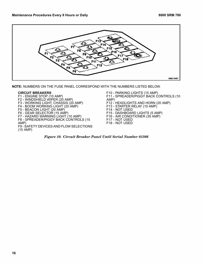
NOTE: NUMBERS ON THE FUSE PANEL CORRESPOND WITH THE NUMBERS LISTED BELOW.
CIRCUIT BREAKERSF1 - ENGINE STOP (10 AMP)F2 - WINDSHIELD WIPER (20 AMP)F3 - WORKING LIGHT, CHASSIS (20 AMP)F4 - BOOM WORKING LIGHT (20 AMP)F5 - BEACON LIGHT (20 AMP)F6 - GEAR SELECTOR (15 AMP)F7 - HAZARD WARNING LIGHT (10 AMP)F8 - SPREADER/PIGGY BACK CONTROLS (15AMP)F9 - SAFETY DEVICES AND FLOW SELECTIONS(15 AMP)
F10 - PARKING LIGHTS (15 AMP)F11 - SPREADER/PIGGY BACK CONTROLS (10AMP)F12 - HEADLIGHTS AND HORN (20 AMP)F13 - STARTER RELAY (10 AMP)F14 - NOT USEDF15 - DASHBOARD LIGHTS (5 AMP)F16 - AIR CONDITIONER (35 AMP)F17 - NOT USEDF18 - NOT USED
Figure 10. Circuit Breaker Panel Until Serial Number 01566
16
8000 SRM 780 Maintenance Procedures Every 8 Hours or Daily
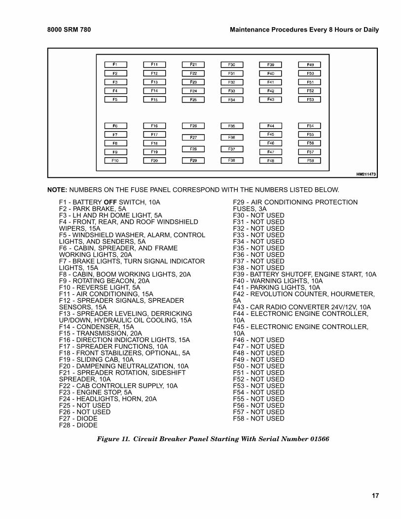
NOTE: NUMBERS ON THE FUSE PANEL CORRESPOND WITH THE NUMBERS LISTED BELOW.
F1 - BATTERY OFF SWITCH, 10AF2 - PARK BRAKE, 5AF3 - LH AND RH DOME LIGHT, 5AF4 - FRONT, REAR, AND ROOF WINDSHIELDWIPERS, 15AF5 - WINDSHIELD WASHER, ALARM, CONTROLLIGHTS, AND SENDERS, 5AF6 - CABIN, SPREADER, AND FRAMEWORKING LIGHTS, 20AF7 - BRAKE LIGHTS, TURN SIGNAL INDICATORLIGHTS, 15AF8 - CABIN, BOOM WORKING LIGHTS, 20AF9 - ROTATING BEACON, 20AF10 - REVERSE LIGHT, 5AF11 - AIR CONDITIONING, 15AF12 - SPREADER SIGNALS, SPREADERSENSORS, 15AF13 - SPREADER LEVELING, DERRICKINGUP/DOWN, HYDRAULIC OIL COOLING, 15AF14 - CONDENSER, 15AF15 - TRANSMISSION, 20AF16 - DIRECTION INDICATOR LIGHTS, 15AF17 - SPREADER FUNCTIONS, 10AF18 - FRONT STABILIZERS, OPTIONAL, 5AF19 - SLIDING CAB, 10AF20 - DAMPENING NEUTRALIZATION, 10AF21 - SPREADER ROTATION, SIDESHIFTSPREADER, 10AF22 - CAB CONTROLLER SUPPLY, 10AF23 - ENGINE STOP, 5AF24 - HEADLIGHTS, HORN, 20AF25 - NOT USEDF26 - NOT USEDF27 - DIODEF28 - DIODE
F29 - AIR CONDITIONING PROTECTIONFUSES, 3AF30 - NOT USEDF31 - NOT USEDF32 - NOT USEDF33 - NOT USEDF34 - NOT USEDF35 - NOT USEDF36 - NOT USEDF37 - NOT USEDF38 - NOT USEDF39 - BATTERY SHUTOFF, ENGINE START, 10AF40 - WARNING LIGHTS, 10AF41 - PARKING LIGHTS, 10AF42 - REVOLUTION COUNTER, HOURMETER,5AF43 - CAR RADIO CONVERTER 24V/12V, 10AF44 - ELECTRONIC ENGINE CONTROLLER,10AF45 - ELECTRONIC ENGINE CONTROLLER,10AF46 - NOT USEDF47 - NOT USEDF48 - NOT USEDF49 - NOT USEDF50 - NOT USEDF51 - NOT USEDF52 - NOT USEDF53 - NOT USEDF54 - NOT USEDF55 - NOT USEDF56 - NOT USEDF57 - NOT USEDF58 - NOT USED
Figure 11. Circuit Breaker Panel Starting With Serial Number 01566
17
Maintenance Procedures Every 8 Hours or Daily 8000 SRM 780
In the battery box there is an additional fuse panel.See Figure 12. This panel protects the indicated cir-cuits shown below:• PF100 (100 amp fuse) provides protection to all
functions behind the battery shutoff.• PF80 (80 amp fuse) provides protection to the
starter motor behind the battery shutoff.• PF50 (50 amp fuse) provides general protection for
the direct battery supplies.
Figure 12. General Fuse Panel
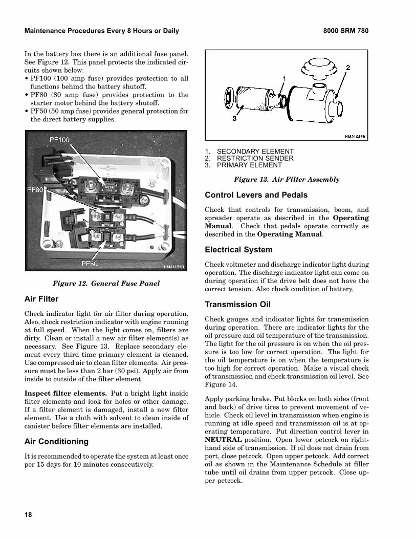
Air Filter
Check indicator light for air filter during operation.Also, check restriction indicator with engine runningat full speed. When the light comes on, filters aredirty. Clean or install a new air filter element(s) asnecessary. See Figure 13. Replace secondary ele-ment every third time primary element is cleaned.Use compressed air to clean filter elements. Air pres-sure must be less than 2 bar (30 psi). Apply air frominside to outside of the filter element.
Inspect filter elements. Put a bright light insidefilter elements and look for holes or other damage.If a filter element is damaged, install a new filterelement. Use a cloth with solvent to clean inside ofcanister before filter elements are installed.
Air Conditioning
It is recommended to operate the system at least onceper 15 days for 10 minutes consecutively.
1. SECONDARY ELEMENT2. RESTRICTION SENDER3. PRIMARY ELEMENT
Figure 13. Air Filter Assembly
Control Levers and Pedals
Check that controls for transmission, boom, andspreader operate as described in the OperatingManual. Check that pedals operate correctly asdescribed in the Operating Manual.
Electrical System
Check voltmeter and discharge indicator light duringoperation. The discharge indicator light can come onduring operation if the drive belt does not have thecorrect tension. Also check condition of battery.
Transmission Oil
Check gauges and indicator lights for transmissionduring operation. There are indicator lights for theoil pressure and oil temperature of the transmission.The light for the oil pressure is on when the oil pres-sure is too low for correct operation. The light forthe oil temperature is on when the temperature istoo high for correct operation. Make a visual checkof transmission and check transmission oil level. SeeFigure 14.
Apply parking brake. Put blocks on both sides (frontand back) of drive tires to prevent movement of ve-hicle. Check oil level in transmission when engine isrunning at idle speed and transmission oil is at op-erating temperature. Put direction control lever inNEUTRAL position. Open lower petcock on right-hand side of transmission. If oil does not drain fromport, close petcock. Open upper petcock. Add correctoil as shown in the Maintenance Schedule at fillertube until oil drains from upper petcock. Close up-per petcock.
18
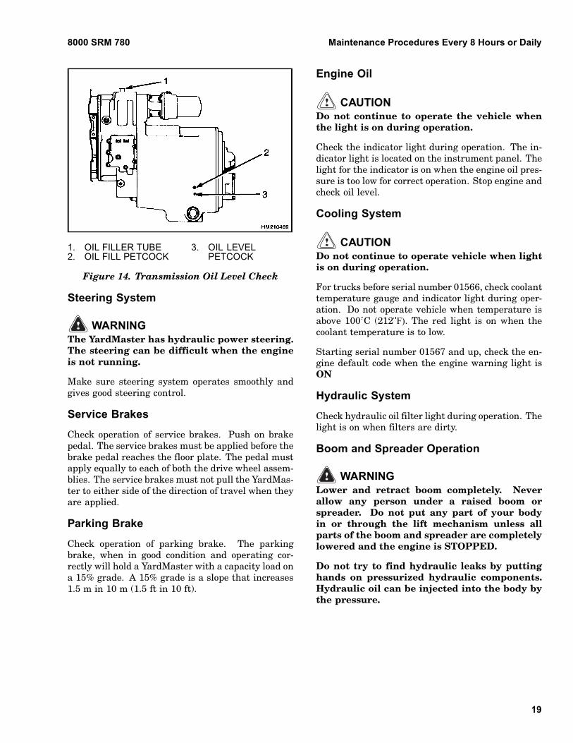
8000 SRM 780 Maintenance Procedures Every 8 Hours or Daily
1. OIL FILLER TUBE2. OIL FILL PETCOCK
3. OIL LEVELPETCOCK
Figure 14. Transmission Oil Level Check
Steering System
WARNINGThe YardMaster has hydraulic power steering.The steering can be difficult when the engineis not running.
Make sure steering system operates smoothly andgives good steering control.
Service Brakes
Check operation of service brakes. Push on brakepedal. The service brakes must be applied before thebrake pedal reaches the floor plate. The pedal mustapply equally to each of both the drive wheel assem-blies. The service brakes must not pull the YardMas-ter to either side of the direction of travel when theyare applied.
Parking Brake
Check operation of parking brake. The parkingbrake, when in good condition and operating cor-rectly will hold a YardMaster with a capacity load ona 15% grade. A 15% grade is a slope that increases1.5 m in 10 m (1.5 ft in 10 ft).
Engine Oil
CAUTIONDo not continue to operate the vehicle whenthe light is on during operation.
Check the indicator light during operation. The in-dicator light is located on the instrument panel. Thelight for the indicator is on when the engine oil pres-sure is too low for correct operation. Stop engine andcheck oil level.
Cooling System
CAUTIONDo not continue to operate vehicle when lightis on during operation.
For trucks before serial number 01566, check coolanttemperature gauge and indicator light during oper-ation. Do not operate vehicle when temperature isabove 100 C (212 F). The red light is on when thecoolant temperature is to low.
Starting serial number 01567 and up, check the en-gine default code when the engine warning light isON
Hydraulic System
Check hydraulic oil filter light during operation. Thelight is on when filters are dirty.
Boom and Spreader Operation
WARNINGLower and retract boom completely. Neverallow any person under a raised boom orspreader. Do not put any part of your bodyin or through the lift mechanism unless allparts of the boom and spreader are completelylowered and the engine is STOPPED.
Do not try to find hydraulic leaks by puttinghands on pressurized hydraulic components.Hydraulic oil can be injected into the body bythe pressure.
19
Maintenance Procedures Every 50 Hours or Weekly 8000 SRM 780
Do the following checks and inspections:
1. Check for leaks in hydraulic system. Check con-dition of hydraulic hoses and tubes.
2. Slowly raise and lower boom several times with-out a load. Extend and retract boom at least once.The boom must raise and lower smoothly.
3. Check that controls for boom and spreader oper-ate the functions correctly. See symbols by eachof the controls.
4. On HR45H units, check that controls for boomand winch operate the functions correctly. Seesymbols by each of the controls.
Maintenance Procedures Every 50 Hours or WeeklyNOTE: Do these procedures in addition to the 8-hourchecks.
BOOM
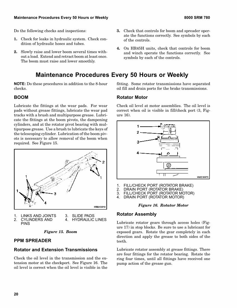
Lubricate the fittings at the wear pads. For wearpads without grease fittings, lubricate the wear padtracks with a brush and multipurpose grease. Lubri-cate the fittings at the boom pivots, the dampeningcylinders, and at the rotator pivot bearing with mul-tipurpose grease. Use a brush to lubricate the keys ofthe telescoping cylinder. Lubrication of the boom piv-ots is necessary to allow removal of the boom whenrequired. See Figure 15.
1. LINKS AND JOINTS2. CYLINDERS AND
PINS
3. SLIDE PADS4. HYDRAULIC LINES
Figure 15. Boom
PPM SPREADER
Rotator and Extension Transmissions
Check the oil level in the transmission and the ex-tension motor at the checkport. See Figure 16. Theoil level is correct when the oil level is visible in the
fitting. Some rotator transmissions have separatedoil fill and drain ports for the brake transmissions.
Rotator Motor
Check oil level at motor assemblies. The oil level iscorrect when oil is visible in fill/check port (3, Fig-ure 16).
1. FILL/CHECK PORT (ROTATOR BRAKE)2. DRAIN PORT (ROTATOR BRAKE)3. FILL/CHECK PORT (ROTATOR MOTOR)4. DRAIN PORT (ROTATOR MOTOR)
Figure 16. Rotator Motor
Rotator Assembly
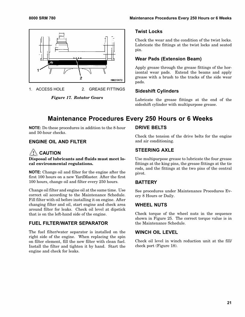
Lubricate rotator gears through access holes (Fig-ure 17) in stop blocks. Be sure to use a lubricant forexposed gears. Rotate the gear completely in eachdirection and apply the grease to both sides of theteeth.
Lubricate rotator assembly at grease fittings. Thereare four fittings for the rotator bearing. Rotate thering four times, until all fittings have received onepump action of the grease gun.
20
8000 SRM 780 Maintenance Procedures Every 250 Hours or 6 Weeks
1. ACCESS HOLE 2. GREASE FITTINGS
Figure 17. Rotator Gears
Twist Locks
Check the wear and the condition of the twist locks.Lubricate the fittings at the twist locks and seatedpin.
Wear Pads (Extension Beam)
Apply grease through the grease fittings of the hor-izontal wear pads. Extend the beams and applygrease with a brush to the tracks of the side wearpads.
Sideshift Cylinders
Lubricate the grease fittings at the end of thesideshift cylinder with multipurpose grease.
Maintenance Procedures Every 250 Hours or 6 WeeksNOTE: Do these procedures in addition to the 8-hourand 50-hour checks.
ENGINE OIL AND FILTER
CAUTIONDisposal of lubricants and fluids must meet lo-cal environmental regulations.
NOTE: Change oil and filter for the engine after thefirst 100 hours on a new YardMaster. After the first100 hours, change oil and filter every 250 hours.
Change oil filter and engine oil at the same time. Usecorrect oil according to the Maintenance Schedule.Fill filter with oil before installing it on engine. Afterchanging filter and oil, start engine and check areaaround filter for leaks. Check oil level at dipstickthat is on the left-hand side of the engine.
FUEL FILTER/WATER SEPARATOR
The fuel filter/water separator is installed on theright side of the engine. When replacing the spinon filter element, fill the new filter with clean fuel.Install the filter and tighten it by hand. Start theengine and check for leaks.
DRIVE BELTS
Check the tension of the drive belts for the engineand air conditioning.
STEERING AXLE
Use multipurpose grease to lubricate the four greasefittings at the king pins, the grease fittings at the tierods, and the fittings at the two pins of the centralpivot.
BATTERY
See procedures under Maintenance Procedures Ev-ery 8 Hours or Daily.
WHEEL NUTS
Check torque of the wheel nuts in the sequenceshown in Figure 25. The correct torque value is inthe Maintenance Schedule.
WINCH OIL LEVEL
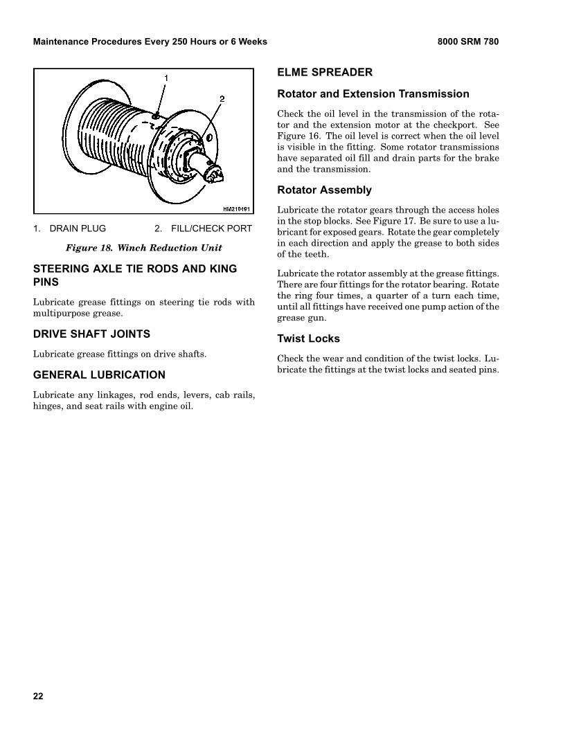
Check oil level in winch reduction unit at the fill/check port (Figure 18).
21
Maintenance Procedures Every 250 Hours or 6 Weeks 8000 SRM 780
1. DRAIN PLUG 2. FILL/CHECK PORT
Figure 18. Winch Reduction Unit
STEERING AXLE TIE RODS AND KINGPINS
Lubricate grease fittings on steering tie rods withmultipurpose grease.
DRIVE SHAFT JOINTS
Lubricate grease fittings on drive shafts.
GENERAL LUBRICATION
Lubricate any linkages, rod ends, levers, cab rails,hinges, and seat rails with engine oil.
ELME SPREADER
Rotator and Extension Transmission
Check the oil level in the transmission of the rota-tor and the extension motor at the checkport. SeeFigure 16. The oil level is correct when the oil levelis visible in the fitting. Some rotator transmissionshave separated oil fill and drain parts for the brakeand the transmission.
Rotator Assembly
Lubricate the rotator gears through the access holesin the stop blocks. See Figure 17. Be sure to use a lu-bricant for exposed gears. Rotate the gear completelyin each direction and apply the grease to both sidesof the teeth.
Lubricate the rotator assembly at the grease fittings.There are four fittings for the rotator bearing. Rotatethe ring four times, a quarter of a turn each time,until all fittings have received one pump action of thegrease gun.
Twist Locks
Check the wear and condition of the twist locks. Lu-bricate the fittings at the twist locks and seated pins.
22
8000 SRM 780 Maintenance Procedures Every 500 Hours or 3 Months
Maintenance Procedures Every 500 Hours or 3 MonthsNOTE: Do these procedures in addition to the 250-hour checks.
AIR FILTER
Replace the central air filter element every 500hours. See Figure 13. See Maintenance ProceduresEvery 8 Hours or Daily for more information.
HYDRAULIC OIL FILTERS
CAUTIONDisposal of lubricants and fluids must meet lo-cal environmental regulations.
When replacing the spin-on filter elements, fill newfilters with clean oil. Install filters and tighten themby hand. Start engine and check for leaks.
TRANSMISSION OIL FILTER
CAUTIONDisposal of lubricants and fluids must meet lo-cal environmental regulations.
NOTE: Change oil filters for the transmission afterthe first 100 hours on new YardMasters. After thefirst 100 hours, change filter every 500 hours.
Remove and install a new oil filter for the transmis-sion. Fill transmission as necessary.
DIFFERENTIAL AND WHEEL ENDHOUSINGS OIL
The oil level in the differential is correct when the oilis even with the plug in the front of the housing. Theoil level in each wheel end housing is correct whenthe oil is even with the plug in the hub cover. Makesure the raised line on the cover is horizontal and theplug is toward the bottom. Add correct oil as specifiedin the Maintenance Schedule.
HYDRAULIC TANK BREATHER
Inspect the filter of the hydraulic tank breather.Clean or replace the filter as needed.
BOOM HORIZONTAL WEAR PADS
Measure the remaining thickness of the horizontalwear pads and replace if the thickness is 21 mm(0.83 in.) or less. Position new wear pads with the"V" of the grooves pointing toward the rear of theboom.
Retract the boom. Verify that the bottom of the innerboom rests in the outer boom. Measure the play be-tween the outer boom and the rear and front upperwear pads.
Reshim wear pad play to 0 to 1 mm (0 to 0.04 in.),if play exceeds 3 mm (0.12 in.). Place shims underthe upper rear pads to reshim at the rear side.Place shims under the lower front wear pads toreshim at the front side. Use medium Loctite on thebolts. Torque the bolts of the wear pads to 130 N•m(96 lbf ft), and the bolts of the pad stops to 200 N•m(148 lbf ft).
BOOM SIDE WEAR PADS
Measure the play between the outer boom and theside wear pads. Reshim the wear pad play to 1 mm(0.04 in.), if the play exceeds 1.5 mm (0.06 in.).Replace the side wear pads when the wear markhas reached; this is when the remaining thicknessis 50 mm (1.97 in.) or less. Apply medium Loctite tothe fixation bolts of the pad support and torque thebolts to 200 N•m (148 lbf ft).
Before adjusting the play, the inner boom has to becentered by means of adjustment bolts of the sidewear pads.
To center the rear of the inner boom, the clearancebetween the LH side clamp plate and the cylinderbracket must be made equal to the clearance of theRH side clamp plate and cylinder bracket. See Fig-ure 19.
23
Maintenance Procedures Every 500 Hours or 3 Months 8000 SRM 780
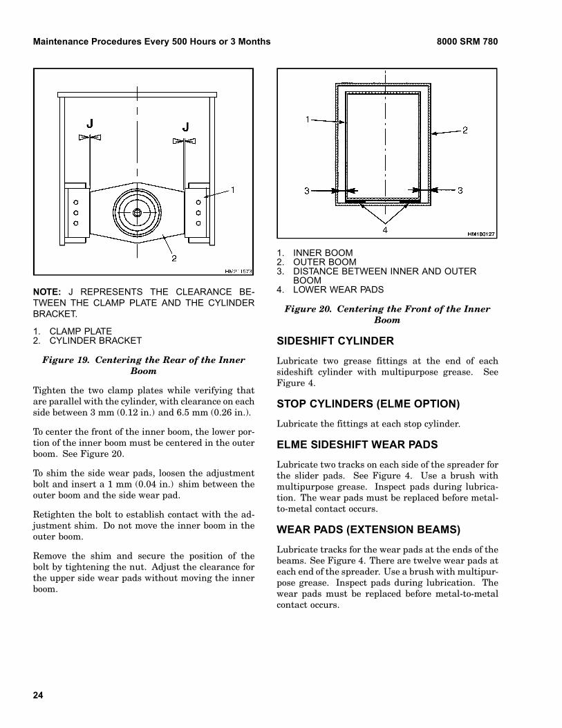
NOTE: J REPRESENTS THE CLEARANCE BE-TWEEN THE CLAMP PLATE AND THE CYLINDERBRACKET.
1. CLAMP PLATE2. CYLINDER BRACKET
Figure 19. Centering the Rear of the InnerBoom
Tighten the two clamp plates while verifying thatare parallel with the cylinder, with clearance on eachside between 3 mm (0.12 in.) and 6.5 mm (0.26 in.).
To center the front of the inner boom, the lower por-tion of the inner boom must be centered in the outerboom. See Figure 20.
To shim the side wear pads, loosen the adjustmentbolt and insert a 1 mm (0.04 in.) shim between theouter boom and the side wear pad.
Retighten the bolt to establish contact with the ad-justment shim. Do not move the inner boom in theouter boom.
Remove the shim and secure the position of thebolt by tightening the nut. Adjust the clearance forthe upper side wear pads without moving the innerboom.
1. INNER BOOM2. OUTER BOOM3. DISTANCE BETWEEN INNER AND OUTER
BOOM4. LOWER WEAR PADS
Figure 20. Centering the Front of the InnerBoom
SIDESHIFT CYLINDER
Lubricate two grease fittings at the end of eachsideshift cylinder with multipurpose grease. SeeFigure 4.
STOP CYLINDERS (ELME OPTION)
Lubricate the fittings at each stop cylinder.
ELME SIDESHIFT WEAR PADS
Lubricate two tracks on each side of the spreader forthe slider pads. See Figure 4. Use a brush withmultipurpose grease. Inspect pads during lubrica-tion. The wear pads must be replaced before metal-to-metal contact occurs.
WEAR PADS (EXTENSION BEAMS)
Lubricate tracks for the wear pads at the ends of thebeams. See Figure 4. There are twelve wear pads ateach end of the spreader. Use a brush with multipur-pose grease. Inspect pads during lubrication. Thewear pads must be replaced before metal-to-metalcontact occurs.
24
8000 SRM 780 Maintenance Procedures Every 1000 Hours or 6 Months
Maintenance Procedures Every 1000 Hours or 6 MonthsNOTE: Do these procedures in addition to the 500-hour checks.
COOLANT FILTER
WARNINGDO NOT remove cap from radiator when en-gine is hot. When the cap is removed, the pres-sure is released from the system. If the systemis hot, the steam and boiling coolant can causeburns.
CAUTIONDisposal of lubricants and fluids must meet lo-cal environmental regulations.
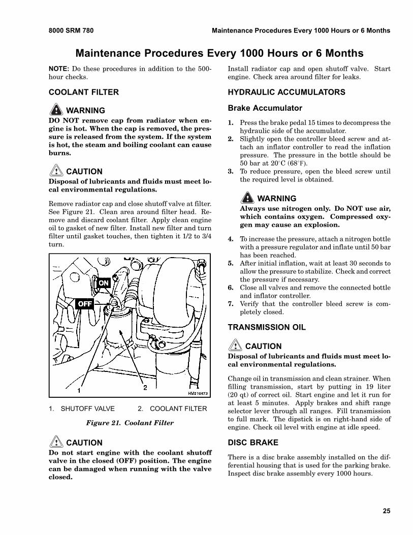
Remove radiator cap and close shutoff valve at filter.See Figure 21. Clean area around filter head. Re-move and discard coolant filter. Apply clean engineoil to gasket of new filter. Install new filter and turnfilter until gasket touches, then tighten it 1/2 to 3/4turn.
1. SHUTOFF VALVE 2. COOLANT FILTER
Figure 21. Coolant Filter
CAUTIONDo not start engine with the coolant shutoffvalve in the closed (OFF) position. The enginecan be damaged when running with the valveclosed.
Install radiator cap and open shutoff valve. Startengine. Check area around filter for leaks.
HYDRAULIC ACCUMULATORS
Brake Accumulator
1. Press the brake pedal 15 times to decompress thehydraulic side of the accumulator.
2. Slightly open the controller bleed screw and at-tach an inflator controller to read the inflationpressure. The pressure in the bottle should be50 bar at 20 C (68 F).
3. To reduce pressure, open the bleed screw untilthe required level is obtained.
WARNINGAlways use nitrogen only. Do NOT use air,which contains oxygen. Compressed oxy-gen may cause an explosion.
4. To increase the pressure, attach a nitrogen bottlewith a pressure regulator and inflate until 50 barhas been reached.
5. After initial inflation, wait at least 30 seconds toallow the pressure to stabilize. Check and correctthe pressure if necessary.
6. Close all valves and remove the connected bottleand inflator controller.
7. Verify that the controller bleed screw is com-pletely closed.
TRANSMISSION OIL
CAUTIONDisposal of lubricants and fluids must meet lo-cal environmental regulations.
Change oil in transmission and clean strainer. Whenfilling transmission, start by putting in 19 liter(20 qt) of correct oil. Start engine and let it run forat least 5 minutes. Apply brakes and shift rangeselector lever through all ranges. Fill transmissionto full mark. The dipstick is on right-hand side ofengine. Check oil level with engine at idle speed.
DISC BRAKE
There is a disc brake assembly installed on the dif-ferential housing that is used for the parking brake.Inspect disc brake assembly every 1000 hours.
25
Maintenance Procedures Every 1000 Hours or 6 Months 8000 SRM 780
WARNINGBrake linings can contain dangerous fibers.Breathing the dust from brake linings is a can-cer or lung disease hazard. Do not create dust!Do not clean brake parts with compressedair or by brushing. Use vacuum equipmentapproved for dangerous fibers or follow thecleaning procedure in this section.
Do not sand, grind, chisel, hammer, or changelinings in any way that will create dust. Anychanges to brake linings must be done in a re-stricted area with special ventilation. Protec-tive clothing and a respirator must be used.
Cleaning Procedures:
1. Do not release dust from brake linings into airwhen checking brakes.
2. Use a solvent to wet the lining dust on the partsof the brake. If a solvent spray is used, do notcreate dust with spray.
3. When lining dust is wet, clean parts. Put anycloth or towels in plastic bag or airtight containerwhile they are still wet. Put a DANGEROUSFIBERS warning label on the plastic bag or air-tight container.
4. Any cleaning cloths that will be washed must becleaned so that fibers are not released into theair.
Inspect
Inspect brake lining and parts of brake assembly forwear or damage. If brake linings are worn or dam-aged, they must be replaced. Brake linings must bereplaced in complete sets. Inspect brake rotor forwear or damage. Check caliper for leaks.
BRAKE SYSTEM OIL AND FILTER
CAUTIONDisposal of lubricants and fluids must meet lo-cal environmental regulations.
Replace oil filter and change oil for the brake systemat the same time. Use oil specified in the Mainte-nance Schedule.
AIR FILTER PRIMARY ELEMENT
Replace the primary air filter element every 1000hours. Clean the inside of the canister. See Fig-ure 13.
HYDRAULIC TANK BREATHER
Replace the hydraulic tank breather.
PPM SPREADER
Extension Beam Horizontal Pads
Measure remaining thickness of the horizontal wearpads. Replace if the thickness is 16 mm (0.63 in.) orless. Use medium Loctite when retorquing the fixa-tion bolts at 100 N•m (74 lbf ft). Check the torque ofall pads and pad holders.
Extension Beam Side Wear Pads
Measure the remaining thickness of the side wearpads. Replace if the thickness if 16 mm (0.63 in.) orless. Use medium Loctite when retorquing the fixa-tion bolts at 100 N•m (74 lbf ft). Check the torque ofall pads and pad holders.
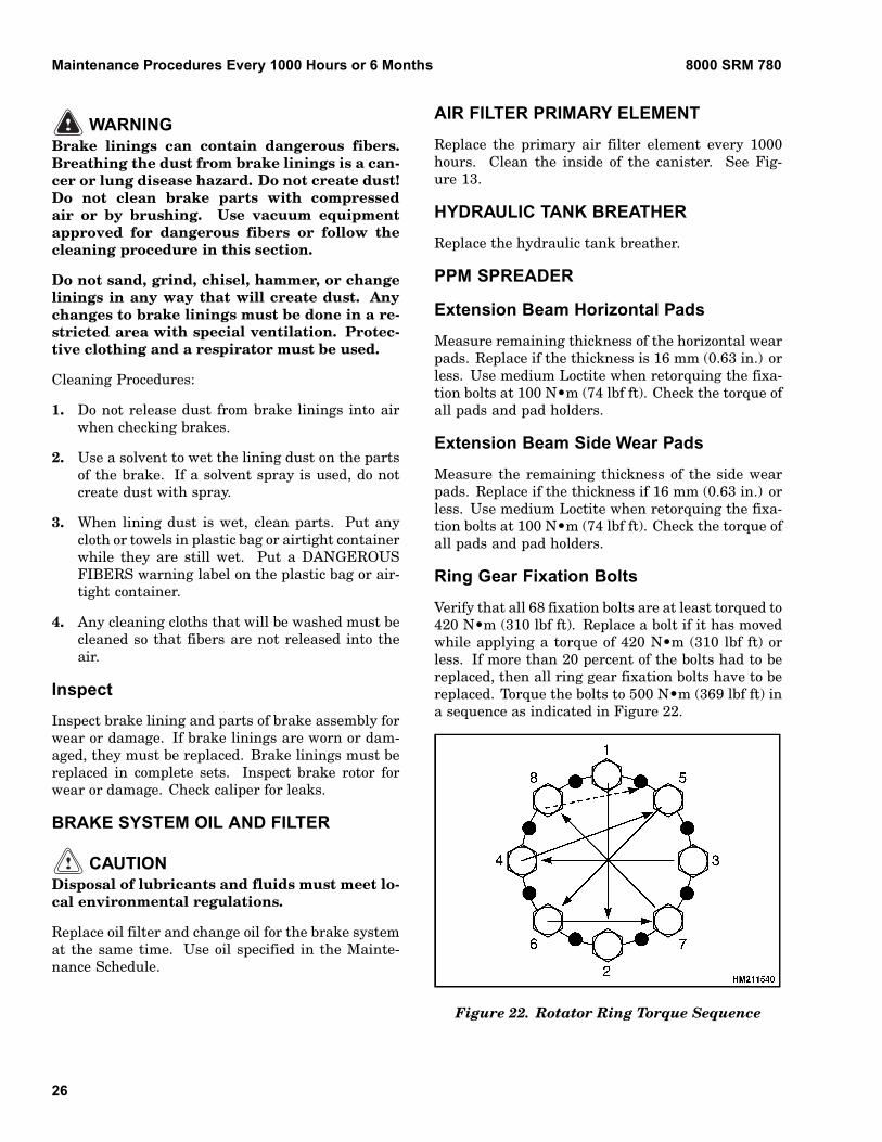
Ring Gear Fixation Bolts
Verify that all 68 fixation bolts are at least torqued to420 N•m (310 lbf ft). Replace a bolt if it has movedwhile applying a torque of 420 N•m (310 lbf ft) orless. If more than 20 percent of the bolts had to bereplaced, then all ring gear fixation bolts have to bereplaced. Torque the bolts to 500 N•m (369 lbf ft) ina sequence as indicated in Figure 22.
Figure 22. Rotator Ring Torque Sequence
26
8000 SRM 780 Maintenance Procedures Every 2000 Hours or Yearly
ELME SPREADER
Wear Pads (Extension Cylinder)
Lubricate tracks for wear pads at the end of the ex-tension cylinders. See Figure 4. Use a brush withmultipurpose grease to lubricate the tracks. Inspectpads during lubrication. The wear pads must be re-placed before metal to metal contact occurs.
WINCH OIL
CAUTIONDisposal of lubricants and fluids must meet lo-cal environmental regulations.
Change oil in the winch reduction unit. See Fig-ure 18. Unwind cable to get access to ports on drum.Rotate drum until drain port is toward bottom. Re-move plug to drain oil. When filling unit, check levelat fill/check port.
PEDALS, LEVERS, HINGES, AND SEATRAILS (GENERAL LUBRICATION)
Lubricate any linkages, rod ends, levers, cab rails,hinges, and seat rails with engine oil.
Maintenance Procedures Every 2000 Hours or YearlyNOTE: Do these procedures in addition to the 1000-hour checks.
ENGINE VALVE ADJUSTMENT
The dealer for Cummins engines maintains and ad-justs the engine. Contact the dealer to make anyvalve adjustments.
HYDRAULIC RELIEF PRESSURES
See the section Hydraulic System YardMaster®
1900 SRM 783. For the boom settings, see the sec-tion Boom YardMaster® 4500 SRM 787. For thespreader settings, see the section Extendable Con-tainer Attachment, PPM 5000 SRM 1063.
COUNTERWEIGHT FIXATION
Verify the torque at 900 N•m (665 lbf ft).
LOAD SENSING SYSTEM
Check for proper operation and settings. See Publi-cation 1495851 (Load Limiter).
DOOR AND WINDOW SEALS
Apply silicon spray before the winter season.
DRIVE AXLE AND DIFFERENTIAL OIL
CAUTIONDisposal of lubricants and fluids must meet lo-cal environmental regulations.
Change the oil in the drive axle and the differential.To drain the oil, remove plugs from the wheel endhousings and the plug at the bottom of the differ-ential housing. Fill drive axle with oil specified inthe Maintenance Schedule. After filling, operate theYardMaster to verify the oil level is even. Check oillevel again and check for leaks.
HYDRAULIC OIL
CAUTIONDisposal of lubricants and fluids must meet lo-cal environmental regulations.
Change oil filters for hydraulic system at the first 50hours of operation on new YardMasters.
Change Hydraulic Oil
WARNINGAt operating temperature, the hydraulic oil isHOT. Do not permit the oil to touch the skin andcause a burn.
1. Put YardMaster on a level surface and retractand lower boom completely. Put a container un-der hydraulic tank. Remove drain plug to drainthe oil.
27

Maintenance Procedures Every 6000 Hours or 2 Years 8000 SRM 780
CAUTIONDo not permit dirt to enter the hydraulic sys-tem when the oil is checked or the filters arechanged.
2. When the hydraulic oil has drained, install drainplug. Fill hydraulic tank with correct oil. Oper-ate system and check for leaks.
STEER WHEEL HUB BEARING CAVITY
Clean and replace the grease in the wheel bearingcavities. Remove the steer wheel as described in theOperator’s Manual. Remove and clean the bear-ing cones in solvent. Verify all of the solvent is outof the bearing cones and completely fill the bearingcones with multipurpose grease. Install the bearingcone as described in the section Steering SystemYardMaster® 1600 SRM 786. Install steer wheel asdescribed in the Operator’s Manual.
BRAKE SYSTEM OIL AND FILTER
CAUTIONDisposal of lubricants and fluids must meet lo-cal environmental regulations.
Replace oil filter and change oil for the brake systemat the same time. Use oil specified in the Mainte-nance Schedule.
ROTOR AND EXTENSION TRANSMISSIONFIXATION BOLTS
Position the blue colored tooth of the rotator ring gearin line with one of the rotator transmissions. Dentalplay should be between 0.1 and 0.3 mm (0.004 and0.012 in.). Rotate the eccentric ring 5 degrees fora movement of 0.1 mm (0.004 in.). Repeat for thesecond rotator transmission.
Retorque the fixation bolts of the rotator and exten-sion transmissions to 210 N•m (155 lbf ft).
ROTATOR AND EXTENSIONTRANSMISSION OIL
CAUTIONDisposal of lubricants and fluids must meet lo-cal environmental regulations.
Change the oil for the transmissions. Note that therotator transmissions can have separated housingswith two filler and two drain plugs or one filler andone drain plug. The oil level is correct when oil isvisible in the fittings. See Figure 16.
Maintenance Procedures Every 6000 Hours or 2 YearsENGINE COOLANT
CAUTIONDisposal of lubricants and fluids must meet lo-cal environmental regulations.
1. Change coolant in cooling system. Put YardMas-ter on a level surface. Stop engine.
WARNINGIf the coolant is hot, do not permit coolant totouch the skin and cause a burn.
2. Open the drain valve. Allow the coolant to draininto a container that will hold approximately40 liter (42 qt). Remove the radiator cap. Flushthe cooling system. Check hoses and fittings asneeded.
3. Close the drain valve. Fill cooling system withcorrect coolant (50% water and 50% ethylene gly-col).
4. Install radiator cap. Start engine. Check forleaks and add additional coolant as necessary.
VIBRATION DAMPER
Verify that the position of the damper has not moved.Replace the damper if the marker line has moved.
TWIST LOCKS
Replace the twist locks. See the section ExtendableContainer Attachment (Elme) 5000 SRM 776.
28
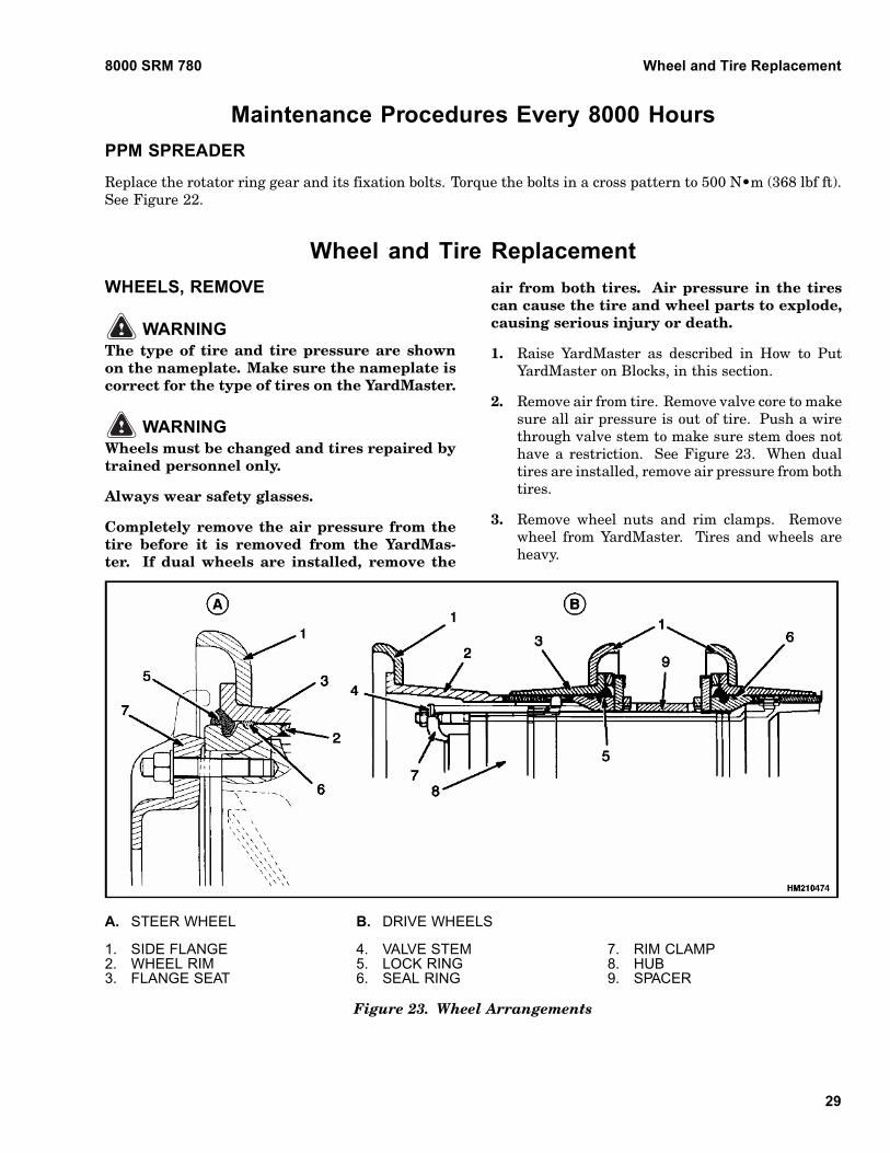
8000 SRM 780 Wheel and Tire Replacement
Maintenance Procedures Every 8000 HoursPPM SPREADER
Replace the rotator ring gear and its fixation bolts. Torque the bolts in a cross pattern to 500 N•m (368 lbf ft).See Figure 22.
Wheel and Tire ReplacementWHEELS, REMOVE
WARNINGThe type of tire and tire pressure are shownon the nameplate. Make sure the nameplate iscorrect for the type of tires on the YardMaster.
WARNINGWheels must be changed and tires repaired bytrained personnel only.
Always wear safety glasses.
Completely remove the air pressure from thetire before it is removed from the YardMas-ter. If dual wheels are installed, remove the
air from both tires. Air pressure in the tirescan cause the tire and wheel parts to explode,causing serious injury or death.
1. Raise YardMaster as described in How to PutYardMaster on Blocks, in this section.
2. Remove air from tire. Remove valve core to makesure all air pressure is out of tire. Push a wirethrough valve stem to make sure stem does nothave a restriction. See Figure 23. When dualtires are installed, remove air pressure from bothtires.
3. Remove wheel nuts and rim clamps. Removewheel from YardMaster. Tires and wheels areheavy.
A. STEER WHEEL B. DRIVE WHEELS
1. SIDE FLANGE2. WHEEL RIM3. FLANGE SEAT
4. VALVE STEM5. LOCK RING6. SEAL RING
7. RIM CLAMP8. HUB9. SPACER
Figure 23. Wheel Arrangements
29
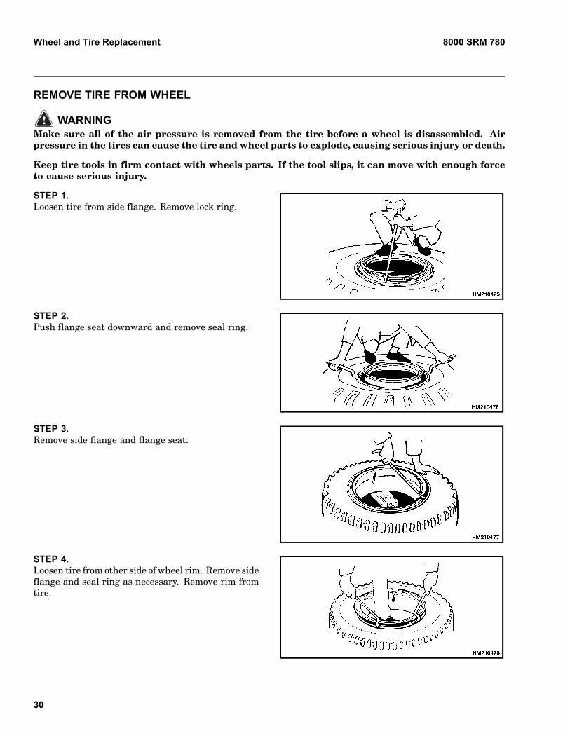
Wheel and Tire Replacement 8000 SRM 780
REMOVE TIRE FROM WHEEL
WARNINGMake sure all of the air pressure is removed from the tire before a wheel is disassembled. Airpressure in the tires can cause the tire and wheel parts to explode, causing serious injury or death.
Keep tire tools in firm contact with wheels parts. If the tool slips, it can move with enough forceto cause serious injury.
STEP 1.Loosen tire from side flange. Remove lock ring.
STEP 2.Push flange seat downward and remove seal ring.
STEP 3.Remove side flange and flange seat.
STEP 4.Loosen tire from other side of wheel rim. Remove sideflange and seal ring as necessary. Remove rim fromtire.
30
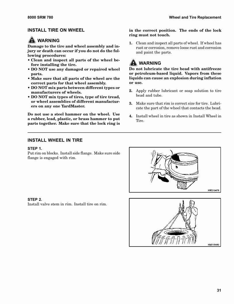
8000 SRM 780 Wheel and Tire Replacement
INSTALL TIRE ON WHEEL
WARNINGDamage to the tire and wheel assembly and in-jury or death can occur if you do not do the fol-lowing procedures:• Clean and inspect all parts of the wheel be-
fore installing the tire.• DO NOT use any damaged or repaired wheel
parts.• Make sure that all parts of the wheel are the
correct parts for that wheel assembly.• DO NOT mix parts between different types or
manufacturers of wheels.• DO NOT mix types of tires, type of tire tread,
or wheel assemblies of different manufactur-ers on any one YardMaster.
Do not use a steel hammer on the wheel. Usea rubber, lead, plastic, or brass hammer to putparts together. Make sure that the lock ring is
in the correct position. The ends of the lockring must not touch.
1. Clean and inspect all parts of wheel. If wheel hasrust or corrosion, remove loose rust and corrosionand paint the parts.
WARNINGDo not lubricate the tire bead with antifreezeor petroleum-based liquid. Vapors from theseliquids can cause an explosion during inflationor use.
2. Apply rubber lubricant or soap solution to tirebead and tube.
3. Make sure that rim is correct size for tire. Lubri-cate the part of the wheel that contacts the bead.
4. Install wheel in tire as shown in Install Wheel inTire.
INSTALL WHEEL IN TIRE
STEP 1.Put rim on blocks. Install side flange. Make sure sideflange is engaged with rim.
STEP 2.Install valve stem in rim. Install tire on rim.
31
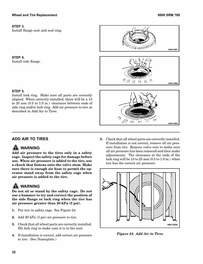
Wheel and Tire Replacement 8000 SRM 780
STEP 3.Install flange seat and seal ring.
STEP 4.Install side flange.
STEP 5.Install lock ring. Make sure all parts are correctlyaligned. When correctly installed, there will be a 13to 25 mm (0.5 to 1.0 in.) clearance between ends ofside ring and/or lock ring. Add air pressure to tire asdescribed in Add Air to Tires.
ADD AIR TO TIRES
WARNINGAdd air pressure to the tires only in a safetycage. Inspect the safety cage for damage beforeuse. When air pressure is added to the tire, usea chuck that fastens onto the valve stem. Makesure there is enough air hose to permit the op-erator stand away from the safety cage whenair pressure is added to the tire.
WARNINGDo not sit or stand by the safety cage. Do notuse a hammer to try and correct the position ofthe side flange or lock ring when the tire hasair pressure greater than 20 kPa (3 psi).
1. Put tire in safety cage. See Figure 24.
2. Add 20 kPa (3 psi) air pressure to tire.
3. Check that all wheel parts are correctly installed.Hit lock ring to make sure it is in the seat.
4. If installation is correct, add correct air pressureto tire. (See Nameplate.)
5. Check that all wheel parts are correctly installed.If installation is not correct, remove all air pres-sure from tire. Remove valve core to make sureall air pressure has been removed and then makeadjustments. The clearance at the ends of thelock ring will be 13 to 25 mm (0.5 to 1.0 in.) whentire has the correct air pressure.
Figure 24. Add Air to Tires
32
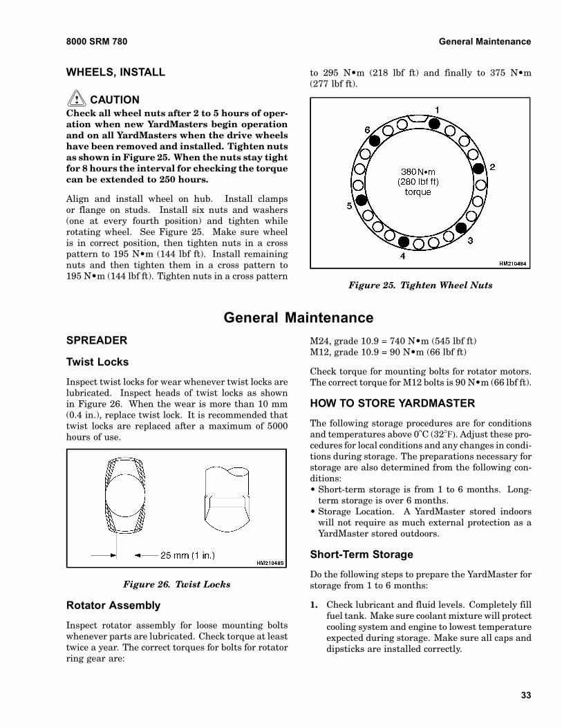
8000 SRM 780 General Maintenance
WHEELS, INSTALL
CAUTIONCheck all wheel nuts after 2 to 5 hours of oper-ation when new YardMasters begin operationand on all YardMasters when the drive wheelshave been removed and installed. Tighten nutsas shown in Figure 25. When the nuts stay tightfor 8 hours the interval for checking the torquecan be extended to 250 hours.
Align and install wheel on hub. Install clampsor flange on studs. Install six nuts and washers(one at every fourth position) and tighten whilerotating wheel. See Figure 25. Make sure wheelis in correct position, then tighten nuts in a crosspattern to 195 N•m (144 lbf ft). Install remainingnuts and then tighten them in a cross pattern to195 N•m (144 lbf ft). Tighten nuts in a cross pattern
to 295 N•m (218 lbf ft) and finally to 375 N•m(277 lbf ft).
Figure 25. Tighten Wheel Nuts
General MaintenanceSPREADER
Twist Locks
Inspect twist locks for wear whenever twist locks arelubricated. Inspect heads of twist locks as shownin Figure 26. When the wear is more than 10 mm(0.4 in.), replace twist lock. It is recommended thattwist locks are replaced after a maximum of 5000hours of use.
Figure 26. Twist Locks
Rotator Assembly
Inspect rotator assembly for loose mounting boltswhenever parts are lubricated. Check torque at leasttwice a year. The correct torques for bolts for rotatorring gear are:
M24, grade 10.9 = 740 N•m (545 lbf ft)M12, grade 10.9 = 90 N•m (66 lbf ft)
Check torque for mounting bolts for rotator motors.The correct torque for M12 bolts is 90 N•m (66 lbf ft).
HOW TO STORE YARDMASTER
The following storage procedures are for conditionsand temperatures above 0 C (32 F). Adjust these pro-cedures for local conditions and any changes in condi-tions during storage. The preparations necessary forstorage are also determined from the following con-ditions:• Short-term storage is from 1 to 6 months. Long-
term storage is over 6 months.• Storage Location. A YardMaster stored indoors
will not require as much external protection as aYardMaster stored outdoors.
Short-Term Storage
Do the following steps to prepare the YardMaster forstorage from 1 to 6 months:
1. Check lubricant and fluid levels. Completely fillfuel tank. Make sure coolant mixture will protectcooling system and engine to lowest temperatureexpected during storage. Make sure all caps anddipsticks are installed correctly.
33
General Maintenance 8000 SRM 780
2. Fully lower and retract boom. Apply thin coat ofengine oil to cylinder rods.
3. Check that all switches and accessories are in theOFF position.
4. If the YardMaster must be left on an incline, putblocks on down hill side of wheels so YardMastercannot move - do not use parking brake.
5. Disconnect battery cables from batteries. Applya protective coat to cable connectors and batteryterminals to prevent corrosion.
6. Check tire pressure. Make sure tires have cor-rect pressure (see Nameplate).
7. Clean engine compartment to prevent corrosion.
8. If YardMaster is not stored in a shelter, put acover over YardMaster to prevent damage fromweather. In wet conditions, a cover will not pre-vent corrosion to a YardMaster that is in long-term storage outside of a dry storage area.
Long-Term Storage
Do the following steps to prepare the YardMaster forstorage for 6 months or longer:
1. Complete all short-term storage procedures.
2. Wrap or cover all exterior lights, radiator grill,and air vents with a moisture barrier cover. Usetape to hold covers in position.
3. Remove batteries from YardMaster. Store batter-ies in an approved space. Be sure to follow localregulations. Batteries that are stored for long pe-riods can become damaged. A recommendation isthat batteries be used in service if possible.
4. Spray exterior surfaces and frame with preser-vative coating.
HOW TO MOVE YARDMASTER ONTRANSPORT
WARNINGStay a safe distance from the edge of docks,ramps, platforms, and other similar workingsurfaces. Watch the tail swing. Remember
when traveling in the forward direction withsteering wheel turned to move the YardMasteraway from the edge of the dock, the rear willswing toward the edge. This can cause theYardMaster to fall off the dock.
WARNINGIF THE YardMaster FALLS OFF THE DOCK,DO NOT JUMP OFF! HOLD FIRMLY TOSTEERING WHEEL, BRACE YOUR FEET,AND LEAN FORWARD AND AWAY FROM THEPOINT OF IMPACT.
Before YardMaster is moved on a transport, checkthe selected route to make sure there is enough clear-ance for YardMaster as loaded on the transport ve-hicle. Bridges, overpasses, power lines, and naturalbarriers can prevent clearance. Removal of the boomand/or spreader can be necessary.
If a trailer is the method of transportation, use blocksin front and back of trailer tires to prevent movementof trailer when YardMaster is loaded and unloaded.If a loading ramp is used, make sure the ramp is thecorrect design and capacity.
Lift YardMaster only at designated lifting points.
Loading
If boom and/or spreader must be removed for trans-port of the YardMaster, see the Service Manual forremoval procedures.
The operator must never leave YardMaster in a con-dition so that it can cause damage and injury. WhenYardMaster is loaded on the transport, do the follow-ing operations:
1. Apply parking brake.
2. Fully lower and retract boom.
3. Put direction control lever for transmission inNEUTRAL.
4. Turn key switch to OFF to stop engine. Checkthat all switches and accessories are turned off.
5. Put blocks in front and back of YardMaster tiresto prevent YardMaster from moving. Make sureblocks are attached to load surface.
34
8000 SRM 780 General Maintenance
WARNINGThe straps or chains used to fasten the Yard-Master to the transport must be directly con-nected to the YardMaster frame or to a com-ponent (drive axle) that is solidly attached tothe frame. Do not fasten a strap or chain tothe boom or spreader to hold the YardMasteron the transport.
CAUTIONMake sure that any straps or chains used tofasten the YardMaster to the transport do notcontact any tubes, hoses, hydraulic cylinders,or other parts of the truck that are easily dam-aged.
If YardMaster is transported in severe weather orany other condition that can damage YardMaster,cover YardMaster. Make sure protective cover is de-signed for the application and is securely fastened.
Unloading
If components normally attached to YardMaster wereremoved for transport, see the Service Manual forinstallation procedures.
1. If used, remove any protective cover.
2. Make sure parking brake is applied.
3. Disconnect straps or chains.
4. Remove wheel blocks.
5. Check that all switches and accessories areturned off.
6. Unload YardMaster.
PREPARATION FOR USE
After being transported or stored, YardMaster mustbe prepared for use for proper operation. All prob-lems must be corrected before use of YardMaster. Seethe Service Manual for procedures.
Preparation After Transport
1. Complete unloading procedures.
2. Inspect YardMaster for damage and missingcomponents.
3. Follow the steps in the section, How to MakeChecks With Engine Stopped.
Preparation After Storage
1. Remove all tape, covers, and preservation mate-rials.
2. Check YardMaster for damage and missing com-ponents. Repair damage and/or replace missingcomponents.
NOTE: If YardMaster has been stored longer than oneyear, all lubricants and fluids must be drained andreplaced. See the section for the fluid specifications.
3. Clean battery cables and terminals. Check bat-tery voltage. If voltage is not correct, charge bat-tery. Connect battery cables to battery.
4. Do the procedures in the section MaintenanceProcedures Every 8 Hours or Daily.
35

NOTES
____________________________________________________________
____________________________________________________________
____________________________________________________________
____________________________________________________________
____________________________________________________________
____________________________________________________________
____________________________________________________________
____________________________________________________________
____________________________________________________________
____________________________________________________________
____________________________________________________________
____________________________________________________________
____________________________________________________________
____________________________________________________________
____________________________________________________________
____________________________________________________________
____________________________________________________________
____________________________________________________________
____________________________________________________________
____________________________________________________________
36


TECHNICAL PUBLICATIONS
8000 SRM 780 6/05 (11/03)(4/03)(2/03)(1/00) Printed in U.S.A.


![PERIODIC CLASSIFICATION & PERIODIC PROPERTIES [ 1 ...youvaacademy.com/youvaadmin/image/PERIODIC TABLE BY RS.pdf · [ 2 ] PERIODIC CLASSIFICATION & PERIODIC PROPERTIES BY RAJESH SHAH](https://img.pdfslide.us/doc/110x75/604570870a43592d4f6b3e29/periodic-classification-periodic-properties-1-table-by-rspdf-2.jpg)