Embed Size (px)
Citation preview

PeriFlo® FMP PERISTALTIC PUMP Bulletin #: IOM-PFL-4502
Installation, Operation & Maintenance Instruction Models: FMP Series 30, 40, 50

Pulsafeeder Factory Service Policy
Should you experience a problem with your PeriFlo FMP pump, first consult the troubleshooting guide in your operation and maintenance manual. If the problem is not covered or cannot be solved, please contact your local Pulsafeeder Sales Representative or our Technical Services Department for further assistance. Trained technicians are available to diagnose your problem and arrange a solution. Solutions may include purchase of replacement parts or returning the unit to the factory for inspection and repair. All returns require a Return Authorization number to be issued by Pulsafeeder. Warranty parts returned as defective, which test good, will be sent back freight collect. No credit will be issued on any replacement electronic parts. Pulsafeeder’s Factory Service Policy is maintained online. Please source this document at this URL: http://www.pulsa.com/pulsa-docs/Pulsafeeder-EPO-Limited-Warranty-Statement.pdf All Pulsafeeder PeriFlo manufactured products are guaranteed against defects in materials and workmanship under normal use for 12 months from the date of shipment from the factory. Any modifications or out-of-warranty repairs will be subject to bench fees and costs associated with replacement parts.
Safety Considerations: 1. Read and understand all related instructions and documentation before attempting to install or
maintain this equipment.
2. Observe all special instructions, notes, and cautions.
3. Act with care and exercise good common sense and judgment during all installation, adjustment, and maintenance procedures.
4. Ensure that all safety and work procedures and standards that are applicable to your company and facility are followed during the installation, maintenance, and operation of this equipment.
Trademarks PeriFlo® is registered trademark of Pulsafeeder Inc.
Pulsafeeder® is a registered trademark of Pulsafeeder, Inc.
Copyright ©2014 Pulsafeeder, Inc. All rights reserved.
Information in this document is subject to change without notice. No part of this publication may be reproduced, stored in a retrieval system or transmitted in any form or any means electronic or mechanical, including photocopying and recording for any purpose other than the purchaser’s personal use without the written permission of Pulsafeeder, Inc.
ii

Table of Contents 1. EQUIPMENT INSPECTION ....................................................................................................................... 1
1.1 General Description ................................................................................................................ 1
1.2 Construction of the Pump ...................................................................................................... 1
1.3 Storage Instructions ............................................................................................................... 2
2. INSTALLATION ...................................................................................................................................... 2
2.1 Location ................................................................................................................................... 2
2.2 Motor ........................................................................................................................................ 3
2.3 Piping System ......................................................................................................................... 3
2.4 Discharge Pressure Requirements ....................................................................................... 5
3. EQUIPMENT STARTUP ........................................................................................................................... 5
3.1 Fastener Inspection ................................................................................................................ 5
3.2 Pump Inspection ..................................................................................................................... 5
3.3 Preliminary Checks ................................................................................................................ 5
3.4 Calibration ............................................................................................................................... 6
4. MAINTENANCE ...................................................................................................................................... 7
4.1 Hose/Tube Inspection, Removal, & Reinstallation .............................................................. 7
4.2 Lubrication .............................................................................................................................. 10
4.3 Hose/Tube Compression and Shimming ............................................................................. 10
4.4 Motor Removal & Reinstallation ............................................................................................ 12
5. REPLACEMENT PARTS .......................................................................................................................... 13
6. TROUBLESHOOTING .............................................................................................................................. 13
7. PIPING ACCESSORIES ........................................................................................................................... 15
8. DIMENSIONAL DRAWING ........................................................................................................................ 16
8.1 FMP30 ...................................................................................................................................... 16
8.2 FMP40 ...................................................................................................................................... 17
8.3 FMP50 ...................................................................................................................................... 18
iii

1. Equipment Inspection Check all equipment for completeness against the order and for any evidence of shipping damage. Shortages or damage must be reported immediately to the carrier and your authorized representative or distributor of PeriFlo pumps.
Included Items: • PeriFlo FMP Peristaltic Pump Optional Items: • Motor (pre-installed at the factory) • Leak Detection • Controls Package • Spare Hoses, Grease or Oil, and Shims
1.1 General Description The PeriFlo® peristaltic pump is constructed with simple yet robust components designed to create continuous, repetitive, positive flow. Modern materials are used to meet the needs of the toughest jobs from aggressive chemicals to highly abrasive slurries.
1.2 Construction of the Pump The diagram below highlights the four main components of the PeriFlo® FMP peristaltic pump. The outer casing (Item 1) contains the pump components and supports the hose/tube. Inside the casing, the rotor (Item 2) supports the two rollers (Items 3). As the rotor turns, the rollers compress the hose/tube (Item 4) to create suction and generate the pumping action. A change in rotor direction will result in a change in direction of the pumped fluid.
Figure 1 - Construction of Pump
1

Hoses are defined as the flexible element for fluid transfer comprised of natural rubber outer layers, nylon reinforcement, and an elastomer inner liner. The inner liner material is to be specified for chemical compatibility; Natural Rubber, EPDM, or Nitrile BUNA Rubber. Hoses are distinguished by their black outer layer of natural rubber and stamped with the inner liner material code. Tubes are defined as the flexible element for fluid transfer made of extruded Norprene. Tubes are distinguished by their cream color and stamped material code. Note that tubes are only available for FMP40 models.
1.3 Storage Instructions Short Term Storage of a PeriFlo FMP pump for up to 6 months is considered short-term. The recommended short-term storage procedures are:
- Store the pump indoors at room temperature in a dry environment. Avoid areas open to inclement weather or excessive humidity.
- Prior to start up; inspect the pump as outlined in Section 3.0.
Long Term
Storage of a PeriFlo FMP pump for over 6 months is considered long-term. If long term storage is anticipated, the following procedures are recommended in addition to the procedures above:
- Remove the hose/tube from the pump and wipe away excess grease. Store in a protective covering, preferably UV resistant, indoors, and lay flat.
- Keep the inside of the pump, the rotor, and rollers lightly greased with Periflo lubricating grease. - Every 12 months the motor should be connected to a power source in accordance with Local,
National and Motor Manufacturer requirements and operated for a minimum of one hour. It is not necessary to have the hose/tube installed during this operation but the suction and discharge ports must be open to atmosphere when the hose/tube is present.
After 12 months storage, Pulsafeeder’s warranty does not cover such items as lubricating grease, gaskets, hose/tubes (if left installed in the pump), and other items which are subject to deterioration with age. If the pump has been in storage for longer than 12 months, it is recommended that these items be replaced prior to going into service. Material and labor to recondition or replace this class of item is the purchaser’s responsibility. Hoses and Tubes Spare hoses and tubes should be stored indoors and in their original protective covering. Always store hoses and tubes on a dry, flat surface. Never rest objects on top of hoses/tubes.
2. Installation 2.1 Location When selecting an installation site or designing a chemical feed system, plan for operation and routine maintenance. Provide 3.25FT (1M) of space around the pump for this purpose.
PeriFlo FMP pumps are designed to operate in an environment where the pump is protected from direct sunlight, and precipitation (i.e., under shelter). The ambient temperature must be between 32° F (0° C) and 104° F (40° C). If necessary, add environmental controls.
2

The pump must be rigidly bolted to a solid and flat foundation to minimize vibration and prevent loosening of the connections. The pump must be level within 5°.
2.2 Motor The PeriFlo FMP is typically shipped with the motor pre-installed. It must be wired in accordance with Local and National requirements by a qualified electrician. Please refer to the motor nameplate for further manufacturer specific information.
If the PeriFlo FMP was purchased less motor, please refer to section 4.4 for further instructions.
2.3 Piping System Attention to piping detail will assure an easy startup and long life of your FMP. Please follow these guidelines: General
- Select piping component materials that are compatible with the fluid type, intended flow rate and pressure, and will not collapse due to internal vacuum.
- It is highly recommended to use a flexible connection between the rigid piping and the pump. This reduces vibration in the piping as well as aids in hose/tube replacement (see Section 4.1.1).
- Pipes should be sized to be equal or slightly larger than the hose/tube diameter. It is recommended to use larger diameter equipment for viscous fluids.
- If making a threaded joint to the connections, use a sealing compound chemically compatible to the process fluid or sealing tape.
Figure 2- Pump P&ID
3

Piping System Recommendations - Both new and existing piping should be cleaned, preferably by flushing with a clean liquid
compatible with process fluid, connection and hose/tube materials. Piping should be blown out with air prior to connection to the pump.
Note - Debris from manufacturing the piping system (e.g., PVC shavings, TFE Tape, dirt, etc.) can be unknowingly assembled inside the pipe. When fluid is introduced this material can be transferred to the pump and damage the hose/tube.
- Piping weight must not be supported by connections or other portions of the pump, as the resulting stresses can cause them to break. When temperature variations are expected, provide for thermal expansion and contraction of piping components so that force and/or moments are controlled within the allowable range.
Suction Piping Location: Successful installations place the pump the shortest distance away from the process fluid supply. Minimal pipe bends and straight pipe runs are also ideal. Isolation Valve and Unions: Isolation valves allow the system to be isolated from the process fluid to facilitate safe servicing. They also aid in the operation of calibration columns. Valves should include good visible indications of open/closed condition. Unions assist with installation and maintenance. Valves that integrate union fittings are ideal. Calibration Column (Optional): Used to calibrate pump performance. Include an isolation valve in the suction line and vent line back to the supply tank to facilitate safe operation. Discharge Piping
Location: Figure 2 depicts the typical discharge piping connections and equipment for a successful installation. Minimal pipe bends and straight pipe runs are ideal. IMPORTANT: DO NOT Install an elbow directly into the discharge connection threaded fitting as it will create excessive back pressure that can lead to premature hose/tube failure.
Pressure Relief Valve: Install a Pressure Relief Valve as close to the pump as possible. Using the leg of a T fitting for this purpose is acceptable (with the normal discharge taking the straight path and the relief flow taking the leg). The relief pressure must be to 10-15% over the system operating pressure but must not exceed the maximum rated discharge pressure of the pump. As a positive displacement pump, the FMP pump will continue to build pressure if the fluid pathway is stopped or blocked potentially resulting in hose/tube failure or “blowout.” NOTE: Failure to install and properly set a Pressure Relief Valve can lead to premature hose/tube failure that will not be covered under warranty.
Pulsation Dampener: Peristaltic pumps do create a pulse of fluid during operation. Installation of an adequately sized Pulsation Dampener will smooth the associated flow/pressure variation to the downstream process.
4

2.4 Discharge Pressure Requirements The specified discharge pressure experienced by the pump is a critical variable in peristaltic pump performance. Each FMP pump is factory set to match the specified discharge pressure in order to fully compress the hose/tube, preventing “back flow.” Accurately specifying the discharge pressure helps find the balance of compression and back pressure to achieve accurate flow and optimize hose/tube life.
Hose Maximum Discharge Pressure: 115psi (8 bar) Tube Maximum Discharge Pressure: 30psi (2 bar)
In the event that the discharge pressure conditions change or the pump requires a change in shimming to achieve specified flow see Section 4.3.
3. Equipment Startup 3.1 Fastener Inspection All pump fasteners should be checked prior to pump operation and occasionally during use. This would include front cover knobs and hardware, motor mounting bolts, base mounting bolts, and the hardware that secures the pump to its foundation.
The front cover knobs should be hand tight with the acorn nut secured with a wrench. Motor mounting bolts and base mounting hardware should be torqued to the following:
Motor Bolt Torque Motor Size Torque (IN-LB / N-M)
56C 96 / 10.8 143TC 96 / 10.8
182TC - 184 TC 216 / 24.4
3.2 Pump Inspection The PeriFlo FMP pump should be checked prior to pump operation and occasionally during use.
- Hose/Tube: Ensure that the hose/tube is properly aligned and completely supported by the roller.
- Lubrication: Check that the entire outside surface of the hose/tube, surface of the rollers, and inside diameter of the pump casing that supports the hose/tube is coated with PeriFlo lubricating grease. The specially formulated grease can be obtained from Pulsafeeder PeriFlo or from an authorized distributor. See Section 4.0 for maintenance guidelines.
3.3 Preliminary Checks - Verify the supply voltage is suitable for the motor. - Verify the optional pump control components are connected to the control panel and test that
they function correctly. - Verify all gauges, valves, and instrumentation are sized and adjusted appropriately for the
application. - Verify that the predicted working conditions, such as flow, pressure, temperature and motor
power, correspond to the application.
5
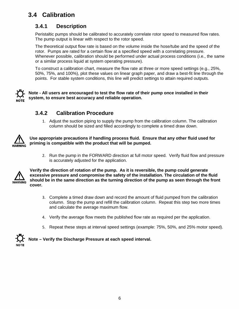
3.4 Calibration
3.4.1 Description Peristaltic pumps should be calibrated to accurately correlate rotor speed to measured flow rates. The pump output is linear with respect to the rotor speed.
The theoretical output flow rate is based on the volume inside the hose/tube and the speed of the rotor. Pumps are rated for a certain flow at a specified speed with a correlating pressure. Whenever possible, calibration should be performed under actual process conditions (i.e., the same or a similar process liquid at system operating pressure).
To construct a calibration chart, measure the flow rate at three or more speed settings (e.g., 25%, 50%, 75%, and 100%), plot these values on linear graph paper, and draw a best-fit line through the points. For stable system conditions, this line will predict settings to attain required outputs.
Note - All users are encouraged to test the flow rate of their pump once installed in their system, to ensure best accuracy and reliable operation.
3.4.2 Calibration Procedure 1. Adjust the suction piping to supply the pump from the calibration column. The calibration
column should be sized and filled accordingly to complete a timed draw down.
Use appropriate precautions if handling process fluid. Ensure that any other fluid used for priming is compatible with the product that will be pumped.
2. Run the pump in the FORWARD direction at full motor speed. Verify fluid flow and pressure
is accurately adjusted for the application.
Verify the direction of rotation of the pump. As it is reversible, the pump could generate excessive pressure and compromise the safety of the installation. The circulation of the fluid should be in the same direction as the turning direction of the pump as seen through the front cover.
3. Complete a timed draw down and record the amount of fluid pumped from the calibration
column. Stop the pump and refill the calibration column. Repeat this step two more times and calculate the average maximum flow.
4. Verify the average flow meets the published flow rate as required per the application.
5. Repeat these steps at interval speed settings (example: 75%, 50%, and 25% motor speed). Note – Verify the Discharge Pressure at each speed interval.
6

4. Maintenance
BEFORE PERFORMING ANY MAINTENANCE REQUIRING REMOVAL OF THE FRONT COVER OR HOSE/TUBE CONNECTIONS, BE SURE TO RELIEVE PRESSURE FROM THE PIPING SYSTEM AND, WHERE HAZARDOUS PROCESS MATERIALS ARE INVOLVED, RENDER THE PUMP SAFE TO PERSONNEL AND THE ENVIRONMENT BY CLEANING AND CHEMICALLY NEUTRALIZING AS APPROPRIATE. WEAR PROTECTIVE CLOTHING AND EQUIPMENT AS APPROPRIATE.
Accurate records from the early stages of pump operation will indicate the type and levels of required maintenance. A preventative maintenance program based on these records will minimize operational problems. The life of the hose/tube, the main wear item of a peristaltic pump, can only be estimated. Since corrosion rates and operational conditions affect functional material life, the life of a hose/tube must be considered according to its particular service conditions.
4.1 Hose/Tube Inspection, Removal, & Reinstallation
IF THE HOSE/TUBE HAS FAILED, PROCESS FLUID MAY HAVE CONTAMINATED OTHER PARTS OF THE PUMP. HANDLE WITH APPROPRIATE CARE.
PeriFlo FMP hoses and tubes do not have a specific cycle life. Periodic hose/tube inspection and replacement are recommended. Each user should perform regular inspections to determine the replacement interval that is appropriate to their system conditions.
Hose/Tube Inspection The following wear characteristics can be attributed to normally accumulated service time, extended service in high pressure and/or high speed applications, incorrect shimming, chemical attack, accumulation of debris, lack of lubrication or contaminated lubrication. See Section 6.0 for corrective actions.
- Outer layer of the hose is peeling/shredding - Hose/tube is flattened or set from idle roller - Cracking/creasing parallel or perpendicular to the hose/tube - Excessive smoothing from rollers - Bulging - Discoloration
4.1.1 Hose/Tube Removal & Reinstallation 1. Disconnect the power source to the drive motor. Follow local Lockout/Tagout procedures.
2. Relieve all pressure from the piping system. Close the inlet and outlet shut off valves.
3. Disconnect piping to the suction and discharge connections and drain any process liquid, following all recommended material safety precautions.
Caution – Process fluid may drain from the Piping. Take necessary precautions.
4. Remove the bolts and washers (Items 1) that fasten the press flange connection assembly (Item 2) to the pump casing on both the suction and discharge ports. Visually inspect for any damage and set aside.
5. Pull the press flange connection assemblies (Item 2) from the hose/tube and remove the closing rings and o-rings (Items 3).
7

If the hose/tube has NOT failed and is being replaced as part of Scheduled Preventative Maintenance (If the hose/tube has failed, proceed to step 11):
6. Reconnect the motor to power and jog the pump FORWARD to push the hose/tube out of the discharge port of the pump.
NEVER place fingers or hands into any part of the pump while the pump is running.
7. Remove the new hose/tube from its protective packaging. Completely coat the new hose/tube with a 1/16” layer of PeriFlo lubricating grease.
8. Place the hose/tube end into the suction port. Reconnect the motor to power and jog the pump FORWARD to draw the hose/tube into the pump through the suction port until the end is through the discharge port. Disconnect the power source to the motor. Follow local Lockout/Tagout procedures.
9. Install the closing rings around the both the hose/tube ends. Check that the o-ring is seated in the press flange connection assembly and press into hose/tube ends. Fasten the press plate to the pump casing.
10. Reconnect suction and discharge piping and prepare the pump for operation.
Figure 3 - Hose Change
8

If the hose/tube has FAILED:
11. Remove the lower drain plug on the backside of the pump to drain any process fluid (disconnect leak detection on models with leak detection option). Take necessary safety precautions.
12. After the press flange connection assemblies and closing rings have been removed, reconnect the motor to power and jog the pump FORWARD to push the hose/tube out of the discharge port of the pump. Wear personal protective equipment as appropriate.
13. Remove the front cover to access the inside of the pump, continuing to follow safety precautions as appropriate.
14. Use a clean cloth or paper towel to wipe away all the remaining grease from inside the pump casing, ports, and around the rotor and rollers. The pump casing and internal components should be free and clear of any process fluid, corrosion, or contaminants before replacing the hose/tube.
15. Check that the rollers continue to spin freely and all fasteners are tight. There should be no visible damage to the rotor, front cover, or front cover o-ring.
16. Replace the front cover and tighten the front cover bolts.
17. Remove the new hose/tube from its protective packaging. Completely coat the new hose/tube and the inside of the cleaned pump casing with a 1/16” layer of PeriFlo lubricating grease.
18. Place the hose/tube end into the suction port. Reconnect the motor to power and jog the pump FORWARD to draw the hose/tube into the pump through the suction port until the end is through the discharge port. Disconnect the power source to the motor. Follow local Lockout/Tagout procedures.
19. Install the closing rings around the both the hose/tube ends. Check that the o-ring is seated in the press flange connection assembly and press into hose/tube ends. Fasten the press plate to the pump casing.
20. Reconnect suction and discharge piping and prepare the pump for operation.
Figure 4 - Hose Change After Failure
9
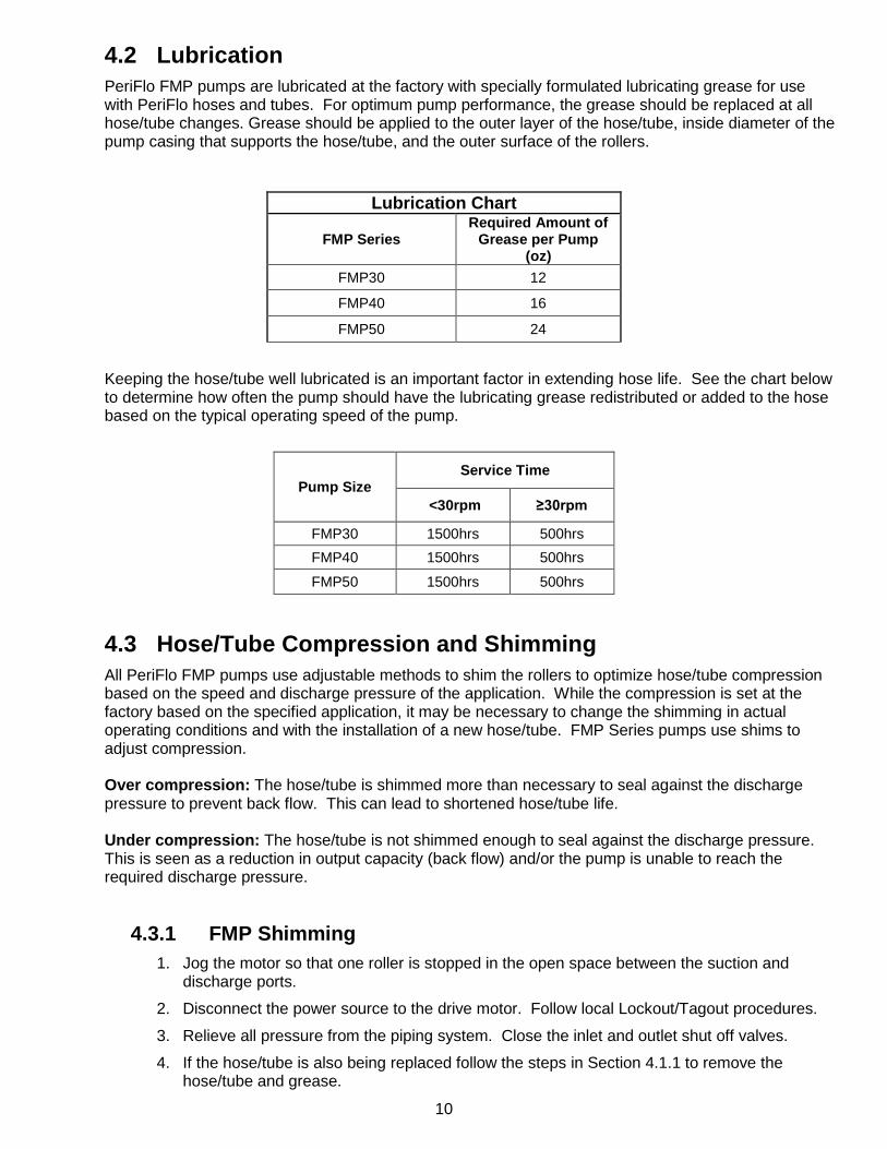
4.2 Lubrication PeriFlo FMP pumps are lubricated at the factory with specially formulated lubricating grease for use with PeriFlo hoses and tubes. For optimum pump performance, the grease should be replaced at all hose/tube changes. Grease should be applied to the outer layer of the hose/tube, inside diameter of the pump casing that supports the hose/tube, and the outer surface of the rollers.
Lubrication Chart
FMP Series Required Amount of
Grease per Pump (oz)
FMP30 12
FMP40 16
FMP50 24
Keeping the hose/tube well lubricated is an important factor in extending hose life. See the chart below to determine how often the pump should have the lubricating grease redistributed or added to the hose based on the typical operating speed of the pump.
Pump Size Service Time
<30rpm ≥30rpm
FMP30 1500hrs 500hrs FMP40 1500hrs 500hrs
FMP50 1500hrs 500hrs
4.3 Hose/Tube Compression and Shimming All PeriFlo FMP pumps use adjustable methods to shim the rollers to optimize hose/tube compression based on the speed and discharge pressure of the application. While the compression is set at the factory based on the specified application, it may be necessary to change the shimming in actual operating conditions and with the installation of a new hose/tube. FMP Series pumps use shims to adjust compression.
Over compression: The hose/tube is shimmed more than necessary to seal against the discharge pressure to prevent back flow. This can lead to shortened hose/tube life.
Under compression: The hose/tube is not shimmed enough to seal against the discharge pressure. This is seen as a reduction in output capacity (back flow) and/or the pump is unable to reach the required discharge pressure.
4.3.1 FMP Shimming 1. Jog the motor so that one roller is stopped in the open space between the suction and
discharge ports.
2. Disconnect the power source to the drive motor. Follow local Lockout/Tagout procedures.
3. Relieve all pressure from the piping system. Close the inlet and outlet shut off valves.
4. If the hose/tube is also being replaced follow the steps in Section 4.1.1 to remove the hose/tube and grease.
10

5. Refer to Figure 5 for item identification. Remove the front cover (Item 4) and hardware (Item 5) to access the inside of the pump, continuing to follow safety precautions as appropriate.
6. Remove the bolts (Items 1 and 2) on the roller support bracket that retain the roller assembly and shims to the rotor. Add or remove shims (Item 4) as necessary and reinstall the roller assembly (Item 3) using the following Torque guide.
Figure 5- FMP Shimming
Note – Some FMP Series pumps are factory shimmed with blocks and shims. A combination of blocks and shims may be required to correctly shim the pump for the expected system discharge pressure.
7. Replace the front cover and hardware. Reconnect the motor to power and jog the motor so that the remaining roller is stopped in the open space between the suction and discharge ports.
NEVER place fingers or hands into any part of the pump while the pump is running.
FMP Series Fastener Torque (IN-LB / N-M)
FMP30 M6 SH Cap Screw (Item 1) 36 / 4.0 M8 Hex Screw (Item 2) 48 / 5.4
FMP40 M8 SH Cap Screw (Item 1) 36 / 4.0 M10Hex Screw (Item 2) 96 / 10.8
FMP50 M8 SH Cap Screw (Item 1) 36 / 4.0 M10 Hex Screw (Item 2) 96 / 10.8
11

8. Disconnect the motor from power following local Lockout/Tagout procedures. Remove the cover and repeat Step 7 to adjust the second roller.
Note – Both roller assemblies must have an equal number of shims to ensure uniform compression of the hose/tube.
9. Replace the front cover and front cover hardware. Prepare the pump for operation. Follow
calibration procedure 3.4 as necessary.
4.4 Motor Removal & Reinstallation Removal
1. Disconnect the power supply to the drive motor. Follow local Lockout/Tagout procedures.
2. Disconnect the motor wiring from the motor.
3. Remove the four bolts retaining the motor to the gear reducer. Slide the motor horizontally to pull the motor shaft out of the gear reducer.
Installation 1. Check the motor key is in place on the motor shaft. Install the motor by sliding the motor
horizontally into the gear reducer.
2. Align the motor bolts holes to the gear reducer mounting plate.
3. Install the 4 motor retaining bolts.
Motor Bolt Torque Motor Size Torque (IN-LB / N-M)
56C 96 / 10.8 143TC 96 / 10.8
182TC - 184 TC 216 / 24.4
4. Connect the motor wiring to the motor in accordance with Local, National and Motor Manufacturer requirements.
5. Restore power.
6. Confirm rotation is correct for the desired pump flow direction.
The PeriFlo FMP is designed to operate with any Motor rotation direction (clockwise or counter clockwise).
12

5. Replacement Parts Throughout the life cycle of the pump the hose or tube will need to be replaced. Each user should perform regular inspections to determine the replacement interval that is appropriate to their system conditions. The replacement hose or tube must be coated with at least a 1/16” thick layer of PeriFlo lubricating grease before installation.
Model Series
Hose/Tube Part Number Material
Lubricating Grease
Part Number Description Grease Req'd per
Hose/Tube (oz) Quantity Required
FMP30
NH040011-RUB NATURAL RUBBER NH980003-001 SILICONE GREASE, 16oz 12 1
NH040011-EPD EPDM NH980003-001 SILICONE GREASE, 16oz 12 1
NH040011-NTR BUNA NH980003-001 SILICONE GREASE, 16oz 12 1
FMP40
NH040014-NRP NORPRENE TUBE NH980003-001 SILICONE GREASE, 16oz 16 1
NH040013-RUB NATURAL RUBBER NH980003-001 SILICONE GREASE, 16oz 16 1
NH040013-EPD EPDM NH980003-001 SILICONE GREASE, 16oz 16 1
NH040013-NTR BUNA NH980003-001 SILICONE GREASE, 16oz 16 1
FMP50
NH040015-RUB NATURAL RUBBER NH980003-001 SILICONE GREASE, 16oz 24 2
NH040015-EPD EPDM NH980003-001 SILICONE GREASE, 16oz 24 2
NH040015-NTR BUNA NH980003-001 SILICONE GREASE, 16oz 24 2
6. Troubleshooting
Difficulty Probable Cause Remedy Pump motor does not start
Faulty power source Check power source Blown fuse, circuit breaker Replace - eliminate overload Broken wire Locate and repair Wired improperly Check diagram Process piping blockage Open valves, clear other obstructions.
No fluid delivery Motor not running. Check power source. Check wiring diagram
Supply tank empty Fill tank Line clogged Clean and flush Closed in-line valve(s) Open valve(s) Under compression Add shims/increase compression
setting Hose/tube ruptured Replace hose/tube
Low fluid delivery Motor speed too low Check voltages, frequency, wiring, and terminal connections Check nameplate vs. specifications Increase motor speed
Calibration system error Evaluate and correct Under compression Add shims to increase hose
compression Hose/tube nearing end of life Evaluate hose/tube condition, replace
as necessary Product viscosity too high Lower viscosity by increasing product
temperature or dilution. Increase pump and/or piping size
13

Delivery gradually drops.
Leak in suction/discharge line Locate and correct Product change Check viscosity and other variables Supply tank vent plugged Unplug vent Hose/tube nearing end of life Evaluate hose/tube condition, replace
as necessary Delivery higher than rated.
Motor speed too high Check voltages, frequency, wiring, and terminal connections Check nameplate vs. specifications Decrease motor speed
Calibration system error Evaluate and correct Short hose/tube life Chemical attack Confirm compatibility of hose/tube,
connections with pumped fluid Excessive pump speed Reduce the speed of the pump Excessive discharge pressure Reduce pressure, reduce pump
speed, increase discharge pipe size High pumping temperature Reduce temperature of product Abnormal elevation in temperature
Check rollers spin freely, apply additional grease
Over compression Remove shims to reduce hose compression
Insufficient quantity of grease Apply additional grease Elevated Temperature
Hose/tube with no grease Apply lubricating grease Elevated temperature of product Reduce product temperature Rollers seized Check fastener torque Excessive pump speed Reduce pump speed
Noisy gearing, knocking
Water hammer Install pulsation dampener Faulty gear reducer Consult factory. Base assembly loose Tighten base hardware
Anchor base Piping noisy. Pipe size too small Increase size of piping
Install pulsation dampener Pipe runs too long Install pulsation dampener in line Pulsation dampener inoperative or flooded
Refill with air or inert gas Inspect and replace diaphragm and recharge
No surge chamber or dampener used
Install pulsation dampeners
Motor overheats. Pump overloaded Check operating conditions against pump design Verify discharge pressure
High or low voltage Check power source Loose wire Trace and correct
Incorrect motor wiring Verify and correct
14
7. Piping Accessories Pressure Relief Valves Pressure relief valves are designed to protect chemical feed systems from damage that may be caused by defective equipment or a blockage in the discharge line. These valves function to limit the pressure downstream of the pump. Field adjust the pressure relief valve to operate when the system pressure exceeds operating discharge pressure by 10-15%. No potentially restrictive components, such as a valve, should be installed between the pump discharge and the PRV.
Pulsation Dampener A pulsation dampener is a pneumatically charged diaphragm-type chamber that intermittently stores hydraulic energy. Used on the inlet, the dampener will stabilize pulsating flow variations as well as provide a full charge of process fluid to the pump. On the discharge line, it will reduce discharge pressure peaks and pulsating flow variations. The pulsation dampener should be charged according to the manufacturer’s instructions.
15

8. Dimensional Drawing Dimensions in inches [mm]
8.1 FMP30
16

8.2 FMP40
17

8.3 FMP50
18

9. Parts Breakdown and Item Numbers
19

20

Consult Factory for FMP50 pumps with motor HP Code “J”
21

22

PeriFlo® FMP PERISTALTIC PUMP Bulletin #: IOM-PFL-4502
Pulsafeeder, Inc. A unit of IDEX Corporation 2883 Brighton Henrietta Town Line Road Rochester NY 14623 +1 (585) 292-8000 www.pulsa.com [email protected]