Embed Size (px)
Citation preview

60 ABB Review 4/2002
The 20-kV GIS switching station recently
installed by Opel Austria Powertrain in
their factory near Vienna is the largest of
its kind in Austria and one of the high-
est-rated in the European automobile
industry. It replaces the original BBC
air-insulated switchgear installed many
years ago in this Fiat-GM Powertrain
group location.
Such switchgear is usually quite no-
ticeable, but at the Opel installation, you
could search long and hard before find-
ing it – it is on the roof!
The reason for choosing such an
unusual location is simple: space. The
large roof area can easily accommodate
capacity upgrades and the power can
be delivered through the roof to the fac-
tory floor below.
In the years after the original installa-
tion, one unexpected problem came to
light: the factory ventilation outlet was
also located on the roof and, over time,
trace amounts of oil in the expelled air
penetrated the switchgear, forming a thin
film on the switch-disconnectors and
the busbars, thus increasing the risk of
current leakage or arcing.
“You could sometimes actually see
arcing on the insulation,” remembers
Roman Szegner, in charge of electrical
systems planning at the Opel plant. Not
surprisingly, frequent inspections were
necessary.
Uprated switchgear reflects
plant expansion
This was not the only reason for replac-
ing the switchgear: The original equip-
ment could easily cover the initial
16 MW power budget, but in the mean-
time demand at the plant, currently pro-
ducing 466,000 engines and 858,000
gearboxes annually, has risen to 27 MW
and will continue to grow - spurred on
in no small part by the imminent intro-
duction of a new six-speed gearbox pro-
duction line, which will be ramped up to
three-shift working in 2004. (The 800,000
gearboxes which will be produced an-
nually will be used in GM and Fiat auto-
mobiles.) Even today, the plant takes
150 GWh from the local utility (Wien-
strom), making it one of their biggest
customers.
“Over the years, cooperation with
News
The new switchgear on the roof of the Opel factory
The 66 gas-insulated 20-kV cubicles of type ZX 1.2
Performance through the roof
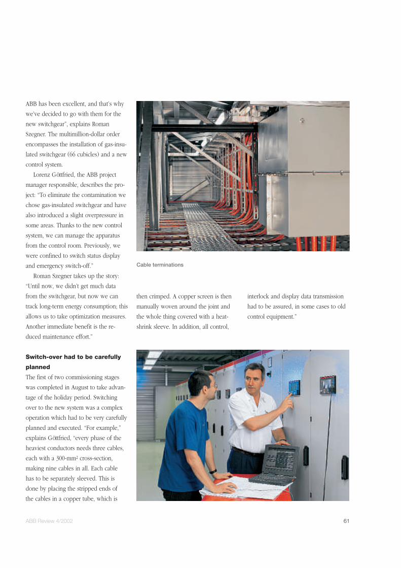
ABB Review 4/2002 61
ABB has been excellent, and that’s why
we’ve decided to go with them for the
new switchgear”, explains Roman
Szegner. The multimillion-dollar order
encompasses the installation of gas-insu-
lated switchgear (66 cubicles) and a new
control system.
Lorenz Göttfried, the ABB project
manager responsible, describes the pro-
ject: “To eliminate the contamination we
chose gas-insulated switchgear and have
also introduced a slight overpressure in
some areas. Thanks to the new control
system, we can manage the apparatus
from the control room. Previously, we
were confined to switch status display
and emergency switch-off.”
Roman Szegner takes up the story:
“Until now, we didn’t get much data
from the switchgear, but now we can
track long-term energy consumption; this
allows us to take optimization measures.
Another immediate benefit is the re-
duced maintenance effort.”
Switch-over had to be carefully
planned
The first of two commissioning stages
was completed in August to take advan-
tage of the holiday period. Switching
over to the new system was a complex
operation which had to be very carefully
planned and executed. “For example,”
explains Göttfried, “every phase of the
heaviest conductors needs three cables,
each with a 300-mm2 cross-section,
making nine cables in all. Each cable
has to be separately sleeved. This is
done by placing the stripped ends of
the cables in a copper tube, which is
then crimped. A copper screen is then
manually woven around the joint and
the whole thing covered with a heat-
shrink sleeve. In addition, all control,
interlock and display data transmission
had to be assured, in some cases to old
control equipment.”
Cable terminations
62 ABB Review 4/2002
A quiet corner of south-east England is
attracting an unusual amount of attention
from the power community these days.
The reason is a new type of energy stor-
age plant with the potential to revolu-
tionize the industry. Called RegenesysTM,
it is based on regenerative fuel cell tech-
nology originally developed by UK util-
ity National Power. Innogy Technology
Ventures Limited, a new company
formed during the de-merger of National
Power, has built the 19-MVA/15 MW
facility alongside its 680-MW combined
cycle power station at Little Barford,
Cambridgeshire. ABB Industry in
Switzerland supplied the facility’s state-
of-the-art power conversion system,
which features innovative IGCT-based
power electronics and advanced control.
With a storage capacity of 120 MWh –
enough to keep 10,000 consumers sup-
plied with electricity for a full day – the
plant is the largest of its kind anywhere
in the world.
Little Barford’s new energy storage fa-
cility will primarily supply electrical
power to black-start the adjacent com-
bined cycle plant and be used for peak
shaving on the connected grid (by stor-
ing surplus generated energy and dis-
charging it during load peaks) as well as
provide reactive power.
The world’s power community is
showing a keen interest in the demon-
stration facility. Following an exhaustive
study, Tennessee Valley Authority (TVA),
the largest public power provider in the
USA, has agreed to install an almost
identical plant to reinforce its power sys-
tem in an area of weak distribution. ABB
is also supplying the complete power
conversion system for this project.
Why store electrical energy?
Electricity is the major commodity of the
21st century but, unlike water, steel,
grain or other commodities, it is difficult
to store. This is why electricity supply
systems are built and operated the way
they are – so that production matches
demand at any moment. Storage has the
obvious advantage that production can
be decoupled from demand.
Scientists and engineers have worked
for many years on developing cost-effi-
cient technologies that would allow elec-
tricity to be stored on a large scale. One
such technology, pumped storage, uses
connected upper and lower water reser-
voirs to provide peak energy. Water is
pumped into the upper reservoir when
electricity is plentiful and then released
to turn turbines that produce electricity
when it is needed. However, this tech-
nology relies on the reservoirs being
at different heights, which restricts its
usefulness to mountainous regions.
Various types of rechargeable batter-
ies have also been used to store electric-
ity in the form of chemical energy.
Known generically as battery energy
storage systems, or BESS, they tend to be
used mostly on a smaller scale.
Storage technologies based on com-
pressed air, flywheels (FESS), super
capacitors or superconducting electro-
magnetic storage (SMES), have also been
developed, but they all suffer from
drawbacks – either technical, environ-
mental, safety or cost – that hamper full
News
B
A
C
D
E
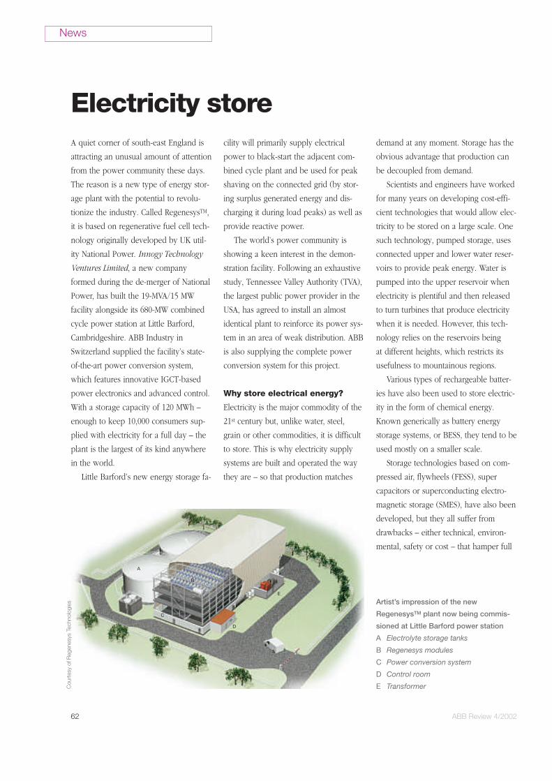
Artist’s impression of the new
RegenesysTM plant now being commis-
sioned at Little Barford power station
A Electrolyte storage tanks
B Regenesys modules
C Power conversion system
D Control room
E Transformer
Electricity store
Cou
rtes
y of
Reg
enes
ys T
echn
olog
ies

ABB Review 4/2002 63
commercial development at the present
time.
RegenesysTM – an alternative
approach
The Regenesys system is based on re-
generative fuel cell technology (some-
times known as redox flow cell technol-
ogy). Electrical energy is converted into
chemical potential energy by ‘charging’
two liquid, water-based electrolyte solu-
tions and subsequently releasing the
stored energy on discharge. The efficient
conversion of electrical to stored chemi-
cal energy and back again can be re-
peated indefinitely. In common with all
DC battery and fuel cell systems, a con-
verter and suitable transformer are re-
quired to connect the system to an AC
network. The technology is environmen-
tally benign; there are no emissions.
What, then, are the differences be-
tween conventional storage batteries and
Regenesys? The defining difference is
that in the former the power output can-
not be decoupled from the actual stored
energy. This is because the energy is
stored through chemical changes on the
surface of the electrodes. Therefore, to
store large amounts of energy, large
numbers of battery cells are needed,
even if the (short-time) power require-
ment can be met with considerably
fewer cells. ‘Flow batteries’ work differ-
ently: here, the energy is stored via
chemical changes to the liquid elec-
trolytes. The energy is discharged and
charged in so-called reactor modules; the
liquid electrolytes are stored in tanks.
Thus, the power output and actual
stored energy are clearly separated from
one another. The number of reactor
modules required is determined by the
maximum amount of power to be dis-
charged/charged, whereas the tank size
defines the amount of energy that can be
stored. Since the tanks cost much less
than reactor modules or battery cells, the
specific first-time costs for the new tech-
nology are comparatively low.
Following successful pilot tests, Inno-
gy decided to build, on a site next to its
Little Barford combined cycle power
plant, a commercial-scale demonstration
facility capable of storing 120 MWh of
energy and of discharging 15 MW. Its
most important task will be to provide
the 680-MW main station with the power
needed to re-start after a grid failure.
The plant will also act as an energy
‘buffer’, storing ‘cheap’ off-peak night-
time energy which it can then supply ‘off
the shelf’ during the day, when demand
is greatest and tariffs are highest.
When commissioned, the plant will
have the ability to start up in less than
10 minutes or, if held in standby mode,
in less than 2 minutes. During operation,
it will be fully connected to the grid, ca-
pable of turning from a state of fully
charging to fully discharging or any state
in between in about 0.02 seconds.
The Regenesys facility comprises four
main sections:
n Storage tanks: These hold the two
electrolytes that are pumped to and from
the regenerative fuel cells when the
plant is charging or discharging.
Electrolytetanks
Regenerative fuel cell module Transformer
Power conversion
How the Regenesys plant
works. More like a small
chemical processing plant
than a traditional power
station, it makes use of
high-grade polymer pipes,
fittings and pumps rather
than large rotating electri-
cal machines.
A Electrolyte inlet mani-
folds
B Bipolar electrodes
C Ion-selective membrane
D Electrical connection
E Electrolyte outlet mani-
folds
Cou
rtes
y of
Reg
enes
ys T
echn
olog
ies

64 ABB Review 4/2002
n Regenerative fuel cells (RFC) into
which the two electrolytes flow. The
electrolytes react through an ion-selec-
tive membrane during charging and dis-
charging, and are pumped back into the
tanks again afterwards.
n Converter/chopper/rectifier: This pro-
vides the electrical interface between the
grid and the voltage characteristics when
charging and discharging the RFC.
During discharges it converts the DC
voltage from the RFC into AC voltage,
and during charging the grid voltage into
a DC voltage.
n Transformer: During RFC discharges
this transforms the converter output volt-
age to the grid voltage, and during
charging steps the grid voltage down to
the voltage required for the converter.
Power conversion system and
process control
A key component of any battery or fuel
cell system is the Power Conversion
System (PCS). The PCS provides the in-
terface between the AC grid supply volt-
age and the variable operating voltage of
the DC modules. The terminal voltage of
the RFC varies considerably, being de-
pendent on the flow direction and mag-
nitude of the power.
The PCS consists of two functionally
separate and autonomous converter sys-
tems as well as the chopper unit (a
DC/DC converter) that provides the link
to the variable voltage of the Regenesys
modules and the DC/AC inverter unit. To
ensure the black-start capability of the
system, self-commutating voltage source
type converters are used. The resulting
system is a four-quadrant converter de-
signed to transfer both reactive and real
power simultaneously and independ-
ently of each other.
Both the chopper and voltage source
converter use the same hardware plat-
form – the very compact IGCT stack de-
sign also used by ABB in various other
applications.
System control for many
operating modes
The normal operating mode would be to
follow a pre-defined schedule of cur-
rent/voltage/time profiles during charg-
ing and discharging, including startup
and shutdown of the system. The sched-
ule is updated on a daily basis to define
the operation for the next 24 hours.
The main system control inputs are
conditioned signals for the system fre-
quency and voltage (supplied by the PCS
control) and the various control mode or-
ders received from the owner’s dispatch
center via a remote communication link.
The main outputs from the RFC plant
are the setpoints for active and reactive
power.
The following functions are imple-
mented in the programmable high-speed
controller’s software:
n Voltage control: Responds to fluctua-
tions in the AC grid, providing voltage
regulation under steady-state as well as
transient operating conditions.
n Frequency regulation: Starts as soon
as the system frequency drops or
changes too fast, such as when spinning
reserves are connected into the grid cir-
cuit.
n Power system stabilization: Damps
power system oscillations by monitoring
frequency fluctuations and controlling
the RFC import/export.
n Auto generation control: Varies the
plant output to match load increas-
es/decreases.
n Constant AC power: Ensures that the
system charges/discharges at a constant
AC power.
News
TransformerAC breaker
Inverter/rectifier
Regenerativefuel cellmodules
Process plantControl system
Auxiliary systems
The main elements of the Regenesys
storage system
Cou
rtes
y of
Reg
enes
ys T
echn
olog
ies
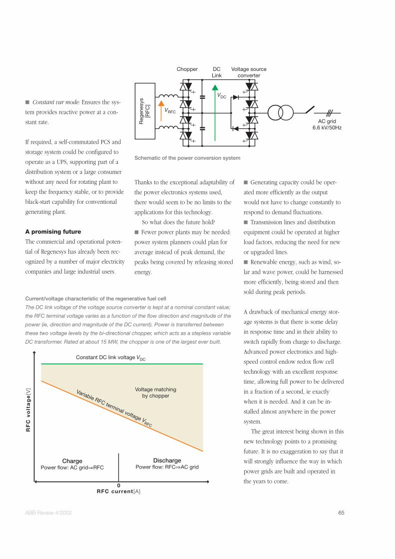
ABB Review 4/2002 65
n Constant var mode: Ensures the sys-
tem provides reactive power at a con-
stant rate.
If required, a self-commutated PCS and
storage system could be configured to
operate as a UPS, supporting part of a
distribution system or a large consumer
without any need for rotating plant to
keep the frequency stable, or to provide
black-start capability for conventional
generating plant.
A promising future
The commercial and operational poten-
tial of Regenesys has already been rec-
ognized by a number of major electricity
companies and large industrial users.
Thanks to the exceptional adaptability of
the power electronics systems used,
there would seem to be no limits to the
applications for this technology.
So what does the future hold?
n Fewer power plants may be needed:
power system planners could plan for
average instead of peak demand, the
peaks being covered by releasing stored
energy.
n Generating capacity could be oper-
ated more efficiently as the output
would not have to change constantly to
respond to demand fluctuations.
n Transmission lines and distribution
equipment could be operated at higher
load factors, reducing the need for new
or upgraded lines.
n Renewable energy, such as wind, so-
lar and wave power, could be harnessed
more efficiently, being stored and then
sold during peak periods.
A drawback of mechanical energy stor-
age systems is that there is some delay
in response time and in their ability to
switch rapidly from charge to discharge.
Advanced power electronics and high-
speed control endow redox flow cell
technology with an excellent response
time, allowing full power to be delivered
in a fraction of a second, ie exactly
when it is needed. And it can be in-
stalled almost anywhere in the power
system.
The great interest being shown in this
new technology points to a promising
future. It is no exaggeration to say that it
will strongly influence the way in which
power grids are built and operated in
the years to come.
RF
C v
olt
ag
e[V
]
0RFC current [A ]
Voltage matchingby chopper
Variable RFC terminal voltage VRFC
Constant DC link voltage VDC
DischargePower flow: RFC⇒AC grid
ChargePower flow: AC grid⇒RFC
Current/voltage characteristic of the regenerative fuel cell
The DC link voltage of the voltage source converter is kept at a nominal constant value;
the RFC terminal voltage varies as a function of the flow direction and magnitude of the
power (ie, direction and magnitude of the DC current). Power is transferred between
these two voltage levels by the bi-directional chopper, which acts as a stepless variable
DC transformer. Rated at about 15 MW, the chopper is one of the largest ever built.
VDC
Chopper DCLink
Voltage sourceconverter
AC grid6.6 kV/50Hz
Reg
enes
ys[R
FC]
VRFC
Schematic of the power conversion system