Embed Size (px)
Citation preview
I:\DE\48\9-1.DOC
For reasons of economy, this document is printed in a limited number. Delegates are kindly asked to bring their copies to meetings and not to request additional copies.
INTERNATIONAL MARITIME ORGANIZATION
IMO
E
SUB-COMMITTEE ON SHIP DESIGN AND EQUIPMENT 48th session Agenda item 9
DE 48/9/1 19 November 2004 Original: ENGLISH
PERFORMANCE TESTING AND APPROVAL STANDARDS FOR SOLAS PERSONAL
LIFE-SAVING APPLIANCES
Reference Test Device (RTD) � Specifications and calibration
Submitted by the United States
SUMMARY
Executive summary:
This document contains specifications for adult, child, and infant size reference test devices for evaluation of in-water performance of candidate SOLAS lifejackets, for the consideration of the Sub-Committee in connection with the proposed amendments to IMO instruments in DE 48/9
Action to be taken:
Paragraph 3
Related documents:
DE 45/9, DE 45/INF.7 and DE 48/9 (paragraph 13)
1 The report of the Correspondence Group on Performance Testing and Approval Standards for SOLAS Personal Life-Saving Appliances, re-established at DE 47 (DE 48/9), included proposals for in-water test procedures based on comparison to the performance of a suitable size reference lifejacket, or reference test device (RTD). General specifications for an adult size RTD were provided earlier to the Sub-Committee in documents DE 45/9 and DE 45/INF.7 (United States). Specifications for child and infant sized RTD�s were circulated within the correspondence group, but have not previously been circulated to the entire Sub-Committee. 2 As discussed in document DE 48/9 (paragraph 13), complete specifications for the adult, child, and infant size RTD�s are attached at annex. An appendix to each annex contains buoyancy tracking and verification data sheets, as were provided to correspondence group members with the sample RTD�s provided for testing and evaluation last year, to ensure that the RTD remains a valid test reference in continued use. Action requested of the Sub-Committee 3 The Sub-Committee is invited to consider the RTD specifications attached at annex, with a view to their inclusion in suitable IMO instruments in connection with requirements based on comparison to an RTD, and decide as appropriate.
***

DE 48/9/1
I:\DE\48\9-1.DOC
ANNEX 1
ADULT REFERENCE TEST DEVICE (RTD) DESIGN AND CONSTRUCTION
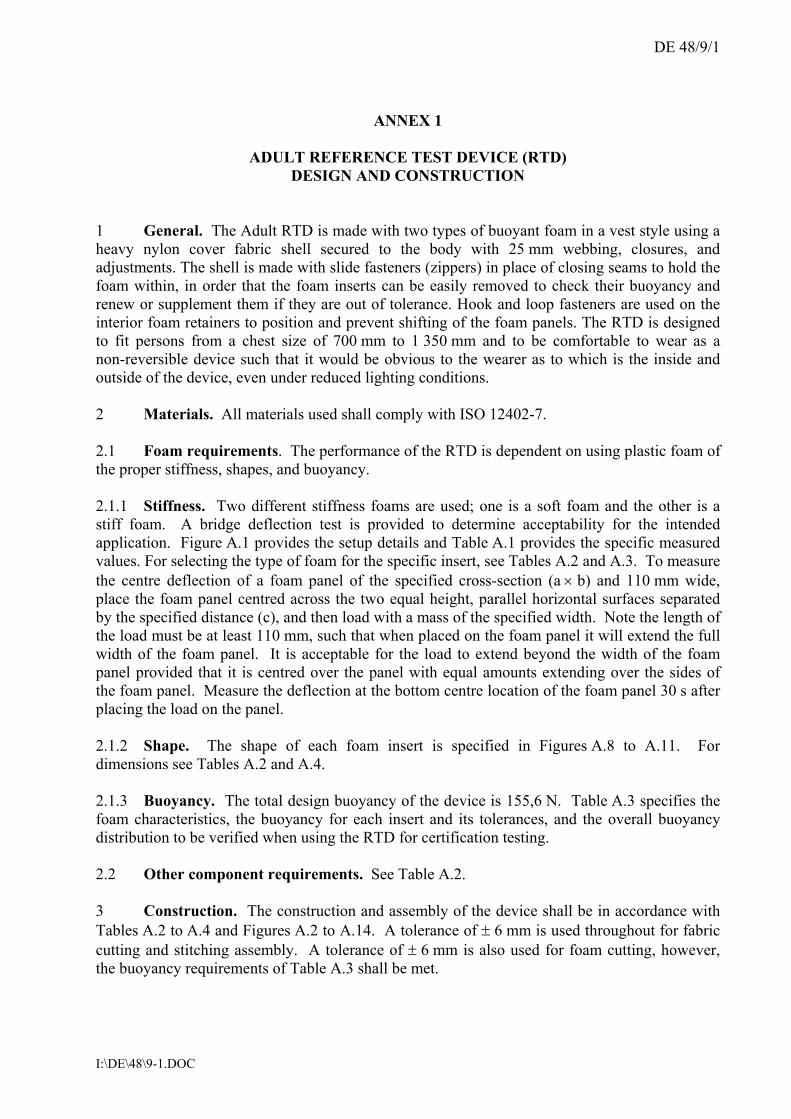
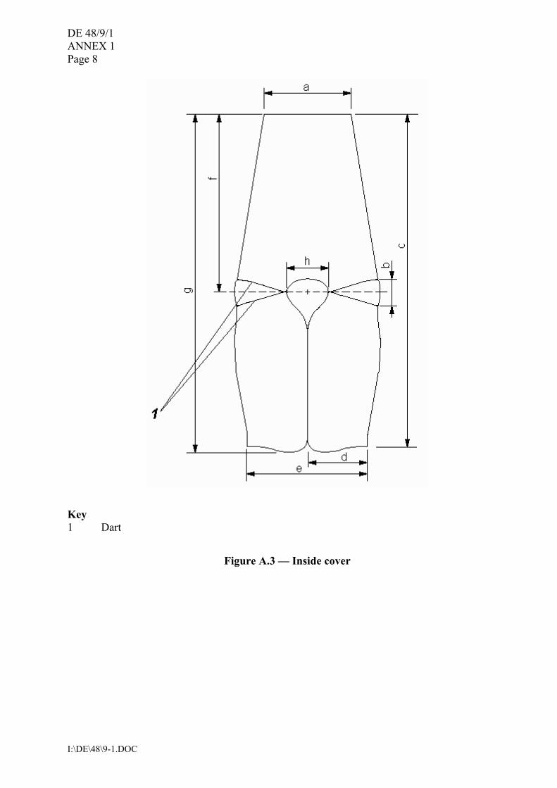
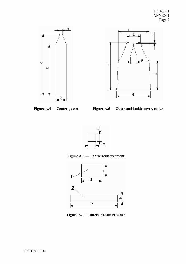
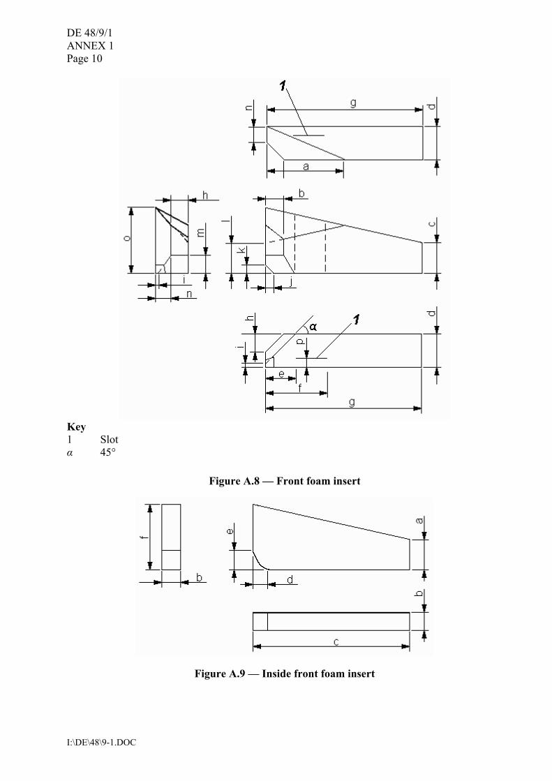
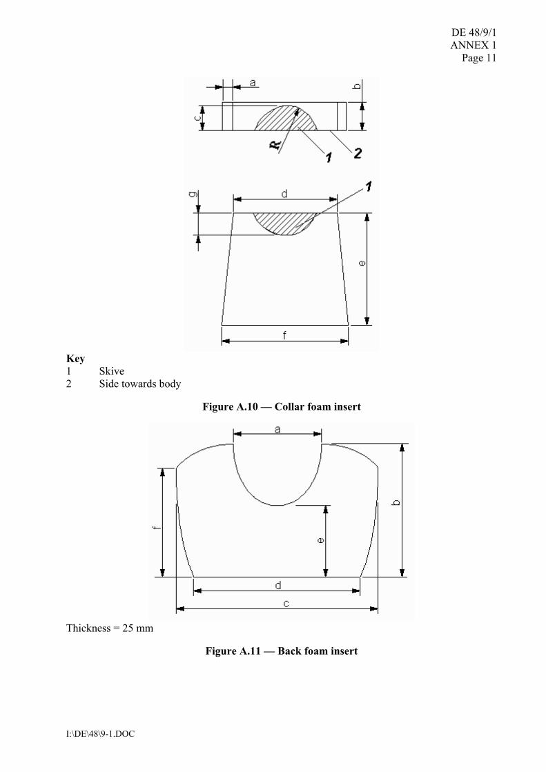
1 General. The Adult RTD is made with two types of buoyant foam in a vest style using a heavy nylon cover fabric shell secured to the body with 25 mm webbing, closures, and adjustments. The shell is made with slide fasteners (zippers) in place of closing seams to hold the foam within, in order that the foam inserts can be easily removed to check their buoyancy and renew or supplement them if they are out of tolerance. Hook and loop fasteners are used on the interior foam retainers to position and prevent shifting of the foam panels. The RTD is designed to fit persons from a chest size of 700 mm to 1 350 mm and to be comfortable to wear as a non-reversible device such that it would be obvious to the wearer as to which is the inside and outside of the device, even under reduced lighting conditions. 2 Materials. All materials used shall comply with ISO 12402-7. 2.1 Foam requirements. The performance of the RTD is dependent on using plastic foam of the proper stiffness, shapes, and buoyancy. 2.1.1 Stiffness. Two different stiffness foams are used; one is a soft foam and the other is a stiff foam. A bridge deflection test is provided to determine acceptability for the intended application. Figure A.1 provides the setup details and Table A.1 provides the specific measured values. For selecting the type of foam for the specific insert, see Tables A.2 and A.3. To measure the centre deflection of a foam panel of the specified cross-section (a × b) and 110 mm wide, place the foam panel centred across the two equal height, parallel horizontal surfaces separated by the specified distance (c), and then load with a mass of the specified width. Note the length of the load must be at least 110 mm, such that when placed on the foam panel it will extend the full width of the foam panel. It is acceptable for the load to extend beyond the width of the foam panel provided that it is centred over the panel with equal amounts extending over the sides of the foam panel. Measure the deflection at the bottom centre location of the foam panel 30 s after placing the load on the panel. 2.1.2 Shape. The shape of each foam insert is specified in Figures A.8 to A.11. For dimensions see Tables A.2 and A.4. 2.1.3 Buoyancy. The total design buoyancy of the device is 155,6 N. Table A.3 specifies the foam characteristics, the buoyancy for each insert and its tolerances, and the overall buoyancy distribution to be verified when using the RTD for certification testing. 2.2 Other component requirements. See Table A.2. 3 Construction. The construction and assembly of the device shall be in accordance with Tables A.2 to A.4 and Figures A.2 to A.14. A tolerance of ± 6 mm is used throughout for fabric cutting and stitching assembly. A tolerance of ± 6 mm is also used for foam cutting, however, the buoyancy requirements of Table A.3 shall be met.
DE 48/9/1 ANNEX 1 Page 2
I:\DE\48\9-1.DOC
3.1 Seams. The seam allowances are 13 mm, unless otherwise specified. All structural seams use a lock type stitch so that the seam will not unravel when a force is applied in the direction of the seam on any of the threads forming the stitch. Stitching should have a density of 7 to 12 stitches per 25 mm of stitch length. The box-x stitching on the webbing is 15 mm × 18 mm, unless otherwise specified. The bar-tack stitching on the webbing is 15 mm × 2 mm. 3.1.1 On the closing seam of the back section of the outer and inside cover, the cut ends of the fabric are turned under and stitched so that the fabric will not ravel. The cut ends of webbing should be heat-sealed. 3.1.2 Tabs on the ends of the waist belt are formed by turning under 40 mm of material twice and stitching 19 mm from the end of the folds with box-x or bar tack stitching.
Key 1 Foam at initial setup 2 Centre load 3 Load 4 Foam bridge deflection after 30 seconds
Figure A.1 � Foam bridge deflection test
DE 48/9/1 ANNEX 1
Page 3
I:\DE\48\9-1.DOC
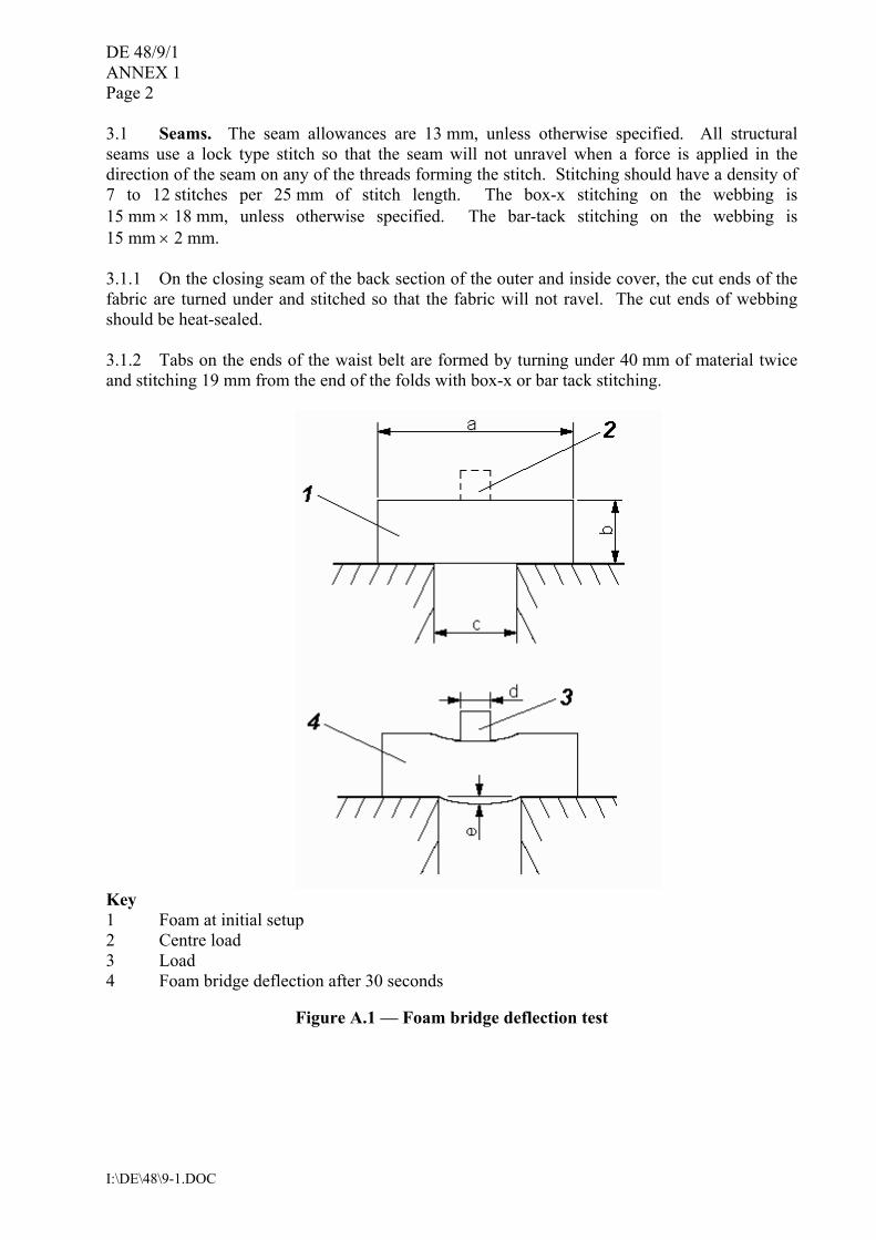
Table A.1 � Specifications for the foam bridge deflection test
Dimension shown in Figure A.1 Load mass
Foam type a
(Length) mm
(Not shown)(Width)
mm
b (Thickness)
mm
c (Span)
mm
d (Load width)
mm
e (Deflection)
mm kg
Stiff 394 110 83 300 120 < 20 8,6 Soft 394 110 45 150 30 ≥ 25 0,75
Table A.2 � Parts, quantity and assembly
Component Description Quantity See Figure Construction notes
1 Cover Fabric 420 denier nylon, with ravel resistant coating, orange
1.1 Front Outer Cover
1 A.2
1.2 Back Outer Cover
1 A.2
1.3 Inside Cover 1 A.3 1.4 Centre Gusset 2 A.4 1.5 Collar, outer and
inside cover 2 A.5
1.6 Fabric reinforcement
4 A.6 A.14
Attach to inside of collar cover, as attachment 1, for reinforcement at webbing attachment (see Figure A.14).
1.7 Interior fabric retainers for foam inserts 1
2 A.7 A.13
Attach to inside of front cover, as attachment 3, stitch to cover at each side to form a foam retainer for inside front foam insert components 2.2.1 and 2.2.2 (see Figure A.13).
1.8 Interior fabric retainers for foam inserts 2
2 A.7 A.14
Attach hoop and loop fasteners to the ends and stitch at centre to the inside of front cover, as attach-ment 4, to form a foam retainer for front foam insert component 2.1.1 and 2.1.2 (see Figure A.13).
2 Foam 2.1 Stiff See Tables A.1 and
A.3
2.1.1 Front foam insert, right side
81 mm thick 1 A.8
2.1.2 Front foam insert, left side
81 mm thick 1 A.8
2.1.3 Collar foam insert
56 mm thick 1 A.10
DE 48/9/1 ANNEX 1 Page 4
I:\DE\48\9-1.DOC
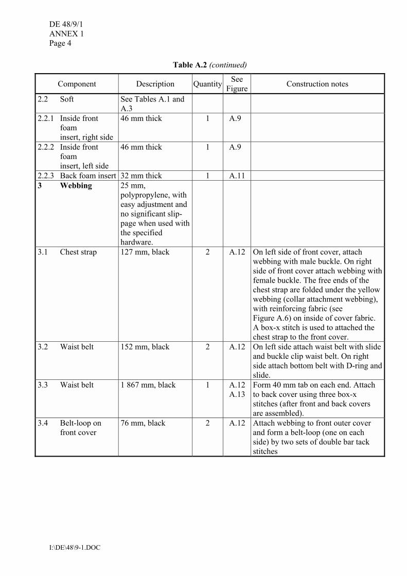
Table A.2 (continued)
Component Description Quantity See Figure Construction notes
2.2 Soft See Tables A.1 and A.3
2.2.1 Inside front foam insert, right side
46 mm thick 1 A.9
2.2.2 Inside front foam insert, left side
46 mm thick 1 A.9
2.2.3 Back foam insert 32 mm thick 1 A.11 3 Webbing 25 mm,
polypropylene, with easy adjustment and no significant slip-page when used with the specified hardware.
3.1 Chest strap 127 mm, black 2 A.12 On left side of front cover, attach webbing with male buckle. On right side of front cover attach webbing with female buckle. The free ends of the chest strap are folded under the yellow webbing (collar attachment webbing), with reinforcing fabric (see Figure A.6) on inside of cover fabric. A box-x stitch is used to attached the chest strap to the front cover.
3.2 Waist belt 152 mm, black 2 A.12 On left side attach waist belt with slide and buckle clip waist belt. On right side attach bottom belt with D-ring and slide.
3.3 Waist belt 1 867 mm, black 1 A.12 A.13
Form 40 mm tab on each end. Attach to back cover using three box-x stitches (after front and back covers are assembled).
3.4 Belt-loop on front cover
76 mm, black 2 A.12 Attach webbing to front outer cover and form a belt-loop (one on each side) by two sets of double bar tack stitches
DE 48/9/1 ANNEX 1
Page 5
I:\DE\48\9-1.DOC
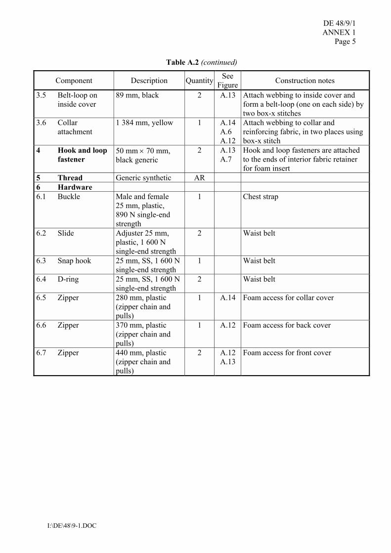
Table A.2 (continued)
Component Description Quantity See Figure Construction notes
3.5 Belt-loop on inside cover
89 mm, black 2 A.13 Attach webbing to inside cover and form a belt-loop (one on each side) by two box-x stitches
3.6 Collar attachment
1 384 mm, yellow 1 A.14 A.6 A.12
Attach webbing to collar and reinforcing fabric, in two places using box-x stitch
4 Hook and loop fastener
50 mm × 70 mm, black generic
2 A.13 A.7
Hook and loop fasteners are attached to the ends of interior fabric retainer for foam insert
5 Thread Generic synthetic AR 6 Hardware 6.1 Buckle Male and female
25 mm, plastic, 890 N single-end strength
1 Chest strap
6.2 Slide Adjuster 25 mm, plastic, 1 600 N single-end strength
2 Waist belt
6.3 Snap hook 25 mm, SS, 1 600 N single-end strength
1 Waist belt
6.4 D-ring 25 mm, SS, 1 600 N single-end strength
2 Waist belt
6.5 Zipper 280 mm, plastic (zipper chain and pulls)
1 A.14 Foam access for collar cover
6.6 Zipper 370 mm, plastic (zipper chain and pulls)
1 A.12 Foam access for back cover
6.7 Zipper 440 mm, plastic (zipper chain and pulls)
2 A.12 A.13
Foam access for front cover
DE 48/9/1 ANNEX 1 Page 6
I:\DE\48\9-1.DOC
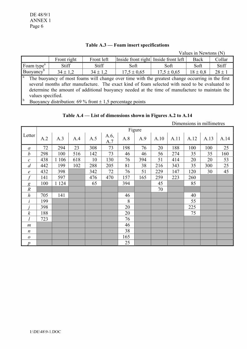
Table A.3 � Foam insert specifications
Values in Newtons (N) Front right Front left Inside front right Inside front left Back Collar
Foam typea Stiff Stiff Soft Soft Soft Stiff Buoyancyb 34 ± 1,2 34 ± 1,2 17,5 ± 0,65 17,5 ± 0,65 18 ± 0,8 28 ± 1 a The buoyancy of most foams will change over time with the greatest change occurring in the first
several months after manufacture. The exact kind of foam selected with need to be evaluated to determine the amount of additional buoyancy needed at the time of manufacture to maintain the values specified.
b Buoyancy distribution: 69 % front ± 1,5 percentage points
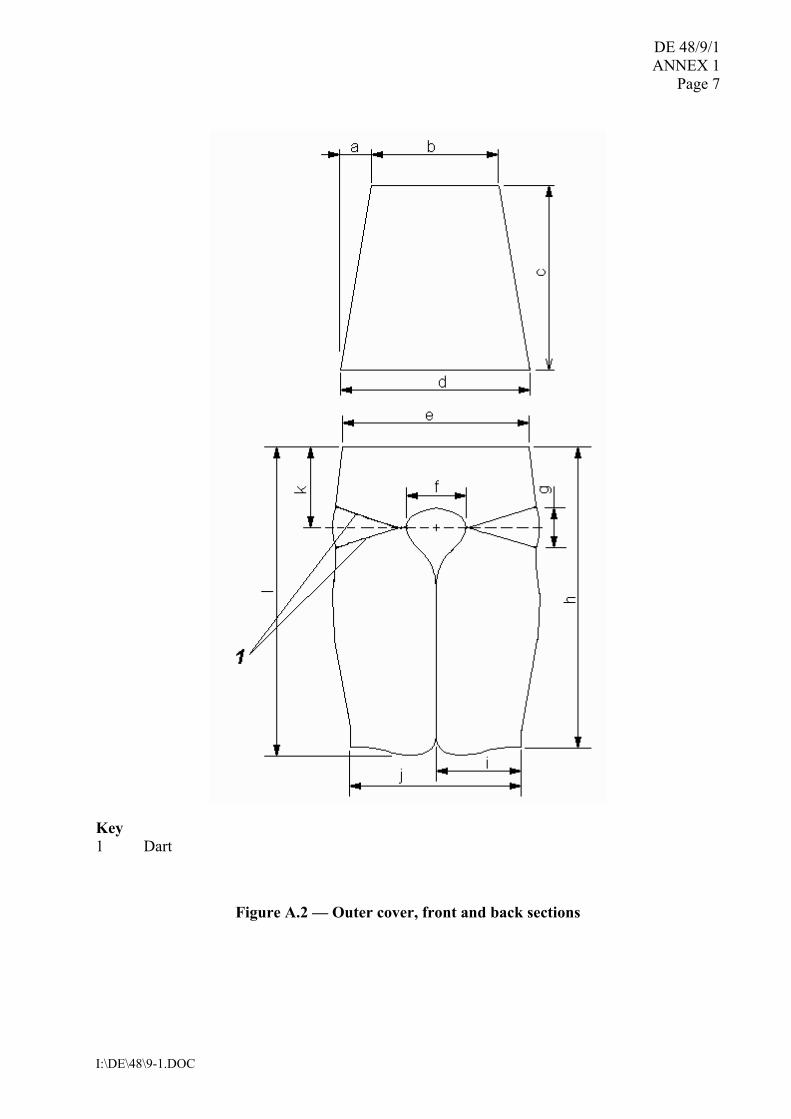
Table A.4 � List of dimensions shown in Figures A.2 to A.14 Dimensions in millimetres
Figure Letter
A.2 A.3 A.4 A.5 A.6, A.7 A.8 A.9 A.10 A.11 A.12 A.13 A.14
a 72 294 23 308 73 198 76 20 188 100 100 25 b 298 100 516 142 73 46 46 56 274 35 35 160 c 438 1 106 618 10 130 76 394 51 414 20 20 53 d 442 199 102 288 205 81 38 216 343 35 300 25 e 432 398 342 72 76 51 229 147 120 30 45 f 141 597 476 470 157 165 259 223 260 g 100 1 124 65 394 45 85 R 70 h 705 141 46 40 i 199 8 55 j 398 20 225 k 188 20 75 l 723 76 m 46 n 38 o 165 p 25
DE 48/9/1 ANNEX 1
Page 7
I:\DE\48\9-1.DOC
Key 1 Dart
Figure A.2 � Outer cover, front and back sections
DE 48/9/1 ANNEX 1 Page 8
I:\DE\48\9-1.DOC
Key 1 Dart
Figure A.3 � Inside cover
DE 48/9/1 ANNEX 1
Page 9
I:\DE\48\9-1.DOC
Figure A.4 � Centre gusset Figure A.5 � Outer and inside cover, collar
Figure A.6 � Fabric reinforcement
Figure A.7 � Interior foam retainer
DE 48/9/1 ANNEX 1 Page 10
I:\DE\48\9-1.DOC
Key 1 Slot α 45°
Figure A.8 � Front foam insert
Figure A.9 � Inside front foam insert
DE 48/9/1 ANNEX 1
Page 11
I:\DE\48\9-1.DOC
Key 1 Skive 2 Side towards body
Figure A.10 � Collar foam insert
Thickness = 25 mm
Figure A.11 � Back foam insert
DE 48/9/1 ANNEX 1 Page 12
I:\DE\48\9-1.DOC
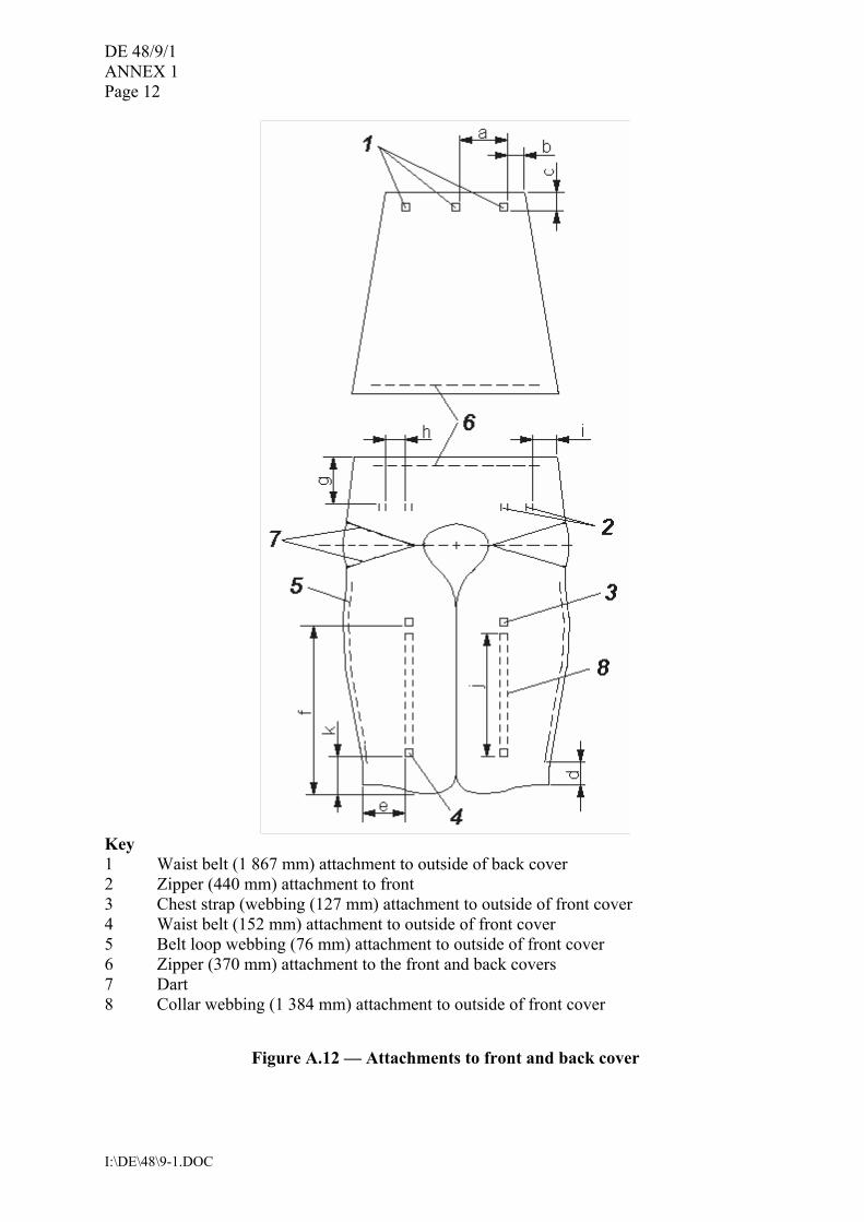
Key 1 Waist belt (1 867 mm) attachment to outside of back cover 2 Zipper (440 mm) attachment to front 3 Chest strap (webbing (127 mm) attachment to outside of front cover 4 Waist belt (152 mm) attachment to outside of front cover 5 Belt loop webbing (76 mm) attachment to outside of front cover 6 Zipper (370 mm) attachment to the front and back covers 7 Dart 8 Collar webbing (1 384 mm) attachment to outside of front cover
Figure A.12 � Attachments to front and back cover
DE 48/9/1 ANNEX 1
Page 13
I:\DE\48\9-1.DOC
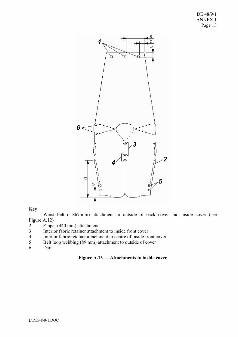
Key 1 Waist belt (1 867 mm) attachment to outside of back cover and inside cover (see Figure A.12) 2 Zipper (440 mm) attachment 3 Interior fabric retainer attachment to inside front cover 4 Interior fabric retainer attachment to centre of inside front cover 5 Belt loop webbing (89 mm) attachment to outside of cover 6 Dart
Figure A.13 � Attachments to inside cover
DE 48/9/1 ANNEX 1 Page 14
I:\DE\48\9-1.DOC
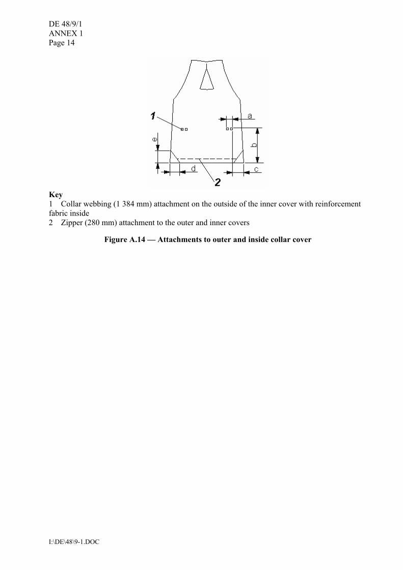
Key 1 Collar webbing (1 384 mm) attachment on the outside of the inner cover with reinforcement fabric inside 2 Zipper (280 mm) attachment to the outer and inner covers
Figure A.14 � Attachments to outer and inside collar cover
DE 48/9/1 ANNEX 1
Page 15
I:\DE\48\9-1.DOC
APPENDIX
RTD Serial number: ___________
ADULT REFERENCE TEST DEVICE � BUOYANCY TRACKING AND
VERIFICATION To achieve repeatability in human subject testing, the overall buoyancy and distribution of buoyancy between the front and back of the RTD must be maintained within a tight tolerance as specified in Table 1.
Table 1 -- SOLAS Adult RTD Buoyancy and Tolerance Limit / Units Front
Buoyancy1 Back Buoyancy
Total Buoyancy Buoyancy Distribution2
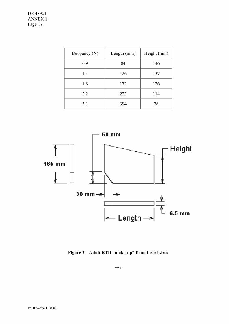
Design / N 103.5 46.5 150 69% in front Maximum / N 107 48 155 70.5% in front Minimum / N 100 45 145 67.5% in front 1 Values at or corrected to standard temperature and pressure. 2 Buoyancy distribution is calculated by dividing the front buoyancy by the total buoyancy. The buoyancy of a new RTD may exceed the allowable tolerance range until the normal shrinkage or compression of the foam inserts stabilizes. Until the buoyancies of the foam inserts have stabilized, buoyancy and distribution should be checked at regular intervals (perhaps weekly), and then at least monthly thereafter or whenever used for testing, whichever is longer. (Frequent use may require more frequent checks.) Only RTD�s with buoyancies within tolerance should be used for certification testing. A data sheet to document the buoyancy and buoyancy distribution of the RTD is attached. Adjustment of buoyancy: At the time of manufacture the left-to-right distribution of buoyancy in the front inserts was adjusted to be within 1.3 N of each other. To achieve this tolerance, thin layers of foam (�make-up� inserts) may have been inserted between the front and inside front foam inserts. The test house may need to increase the size of these make-up inserts from time to time to keep these parameters within tolerance, or may need to add buoyancy to the back or collar inserts (or trim buoyancy, if the back insert has not shrunk as anticipated). Figure 2 provides guidance for sizing of make-up inserts to adjust buoyancy. After a full sheet of 6.5 mm thick foam is required in any one of the four major areas, an inside front or back insert probably needs to be replaced. If the front buoyancy is under the minimum value, measure the buoyancy of the right and left sides so that the proper distribution of buoyancy (no more than a 1.3 N difference) between the right and left front panels can be maintained.
Table 2 � SOLAS Adult RTD Insert Design Buoyancies Combined Left Front &
Inside Front 1 Combined Right Front &
Inside Front 1 Back Collar
Design (N) 34 + 17.75 = 51.75 34 + 17.75 = 51.75 18.5 28 S/N ____ Date:
1 Plus make-up inserts, if used
DE 48/9/1 ANNEX 1 Page 16
I:\DE\48\9-1.DOC
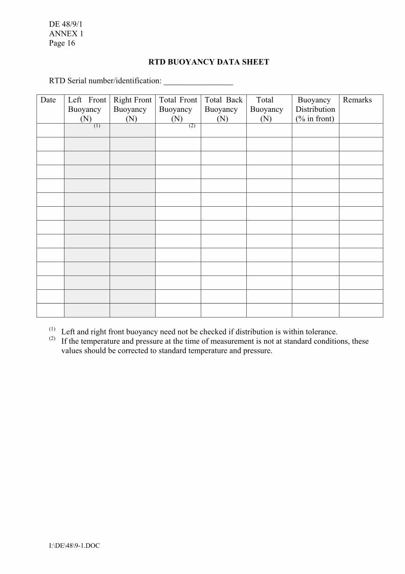
RTD BUOYANCY DATA SHEET RTD Serial number/identification: _________________
Date Left Front Buoyancy (N)
Right Front Buoyancy (N)
Total Front Buoyancy (N)
Total Back Buoyancy (N)
Total Buoyancy (N)
Buoyancy Distribution (% in front)
Remarks
(1) (2)
(1) Left and right front buoyancy need not be checked if distribution is within tolerance. (2) If the temperature and pressure at the time of measurement is not at standard conditions, these
values should be corrected to standard temperature and pressure.
DE 48/9/1 ANNEX 1
Page 17
I:\DE\48\9-1.DOC
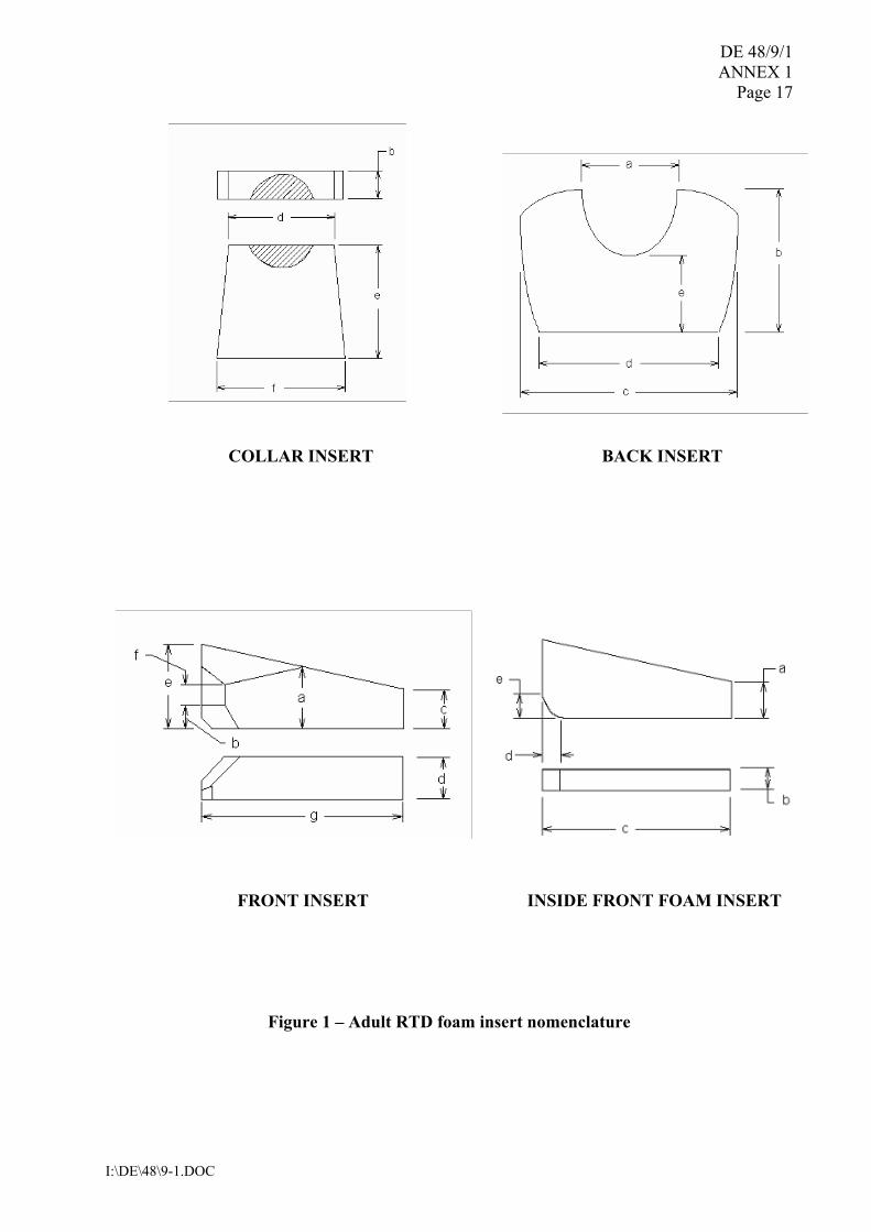
COLLAR INSERT BACK INSERT FRONT INSERT INSIDE FRONT FOAM INSERT
Figure 1 � Adult RTD foam insert nomenclature
DE 48/9/1 ANNEX 1 Page 18
I:\DE\48\9-1.DOC
Buoyancy (N) Length (mm) Height (mm)
0.9 84 146
1.3 126 137
1.8 172 126
2.2 222 114
3.1 394 76
Figure 2 � Adult RTD �make-up� foam insert sizes
***
DE 48/9/1
I:\DE\48\9-1.DOC
ANNEX 2
CHILD REFERENCE TEST DEVICE (RTD) DESIGN AND CONSTRUCTION
1 General. The Child RTD is for persons weighing approximately 15 to 43 kg, or 100 to 155 cm in height. This RTD is made with layers of buoyant foam in a bib-style design using a heavy nylon shell cover fabric secured to the body with a waist belt with quick and positive closure and adjustment, along with a chest strap at the neck for closure and adjustment. The shell is made with slide fasteners (zippers) in place of closing seams to hold the foam within, in order that the foam inserts can be easily removed to check their buoyancy and renew or supplement them if they are out of tolerance. The device is designed to fit persons with chest sizes from 50 cm to 70 cm. The RTD is designed to be reasonably comfortable to wear as a non-reversible device. 2 Materials. All materials used shall comply with ISO 12402-7. 2.1 Foam requirements. The performance of the RTD is dependent on using plastic foam of the proper stiffness, shapes, and buoyancy. 2.1.1 Stiffness. The buoyant inserts are made of layers of medium stiffness foam to create a flexible but firm buoyancy element. 2.1.2 Shape. The shape of each foam layer is identified in Figures B.2 and B.3. Dimensions are in Tables B.1, B.2 and B.3. 2.1.3 Buoyancy. The total design buoyancy of the device is 88 N. Table B.4 specifies foam characteristics, the buoyancy for each insert and its tolerances, and the overall buoyancy distribution to be verified when using the RTD for certification testing. 2.2 Other component requirements. See Table B.1. 3 Construction. The construction and assembly of the device shall be in accordance with Tables B.1 and B.5 and Figures B.1 through B.9. A tolerance of ± 6 mm is used throughout for fabric cutting and stitching assembly. A tolerance of ± 6 mm is also used for foam cutting, however, the buoyancy requirements of Table A.3 shall be met. 3.1 Seams. Seam allowances are 13 mm, unless otherwise specified. All structural seams use a lock type stitch so that the seam will not unravel when a force is applied in the direction of the seam on any of the threads forming the stitch. Stitching should have a density of 7 � 12 stitches per 25 mm of stitch length. Box-x stitching on the webbing is 30 x 15 mm for the waist belt and 15 x 13 mm for the belt loop and chest strap, unless otherwise specified. The bar-tack stitching on webbing is 30 x 2 mm for the waist belt and 15 x 2 mm for the belt loop and chest strap. 3.1.1 The fabric reinforcements for the waist belt, belt loop, and chest strap should be attached to the inside surface of the outside cover before attaching any of these items. On the closing seam of the top and bottom sections of the outside and inside cover, the cut ends of the fabric is
DE 48/9/1 ANNEX 2 Page 2
I:\DE\48\9-1.DOC
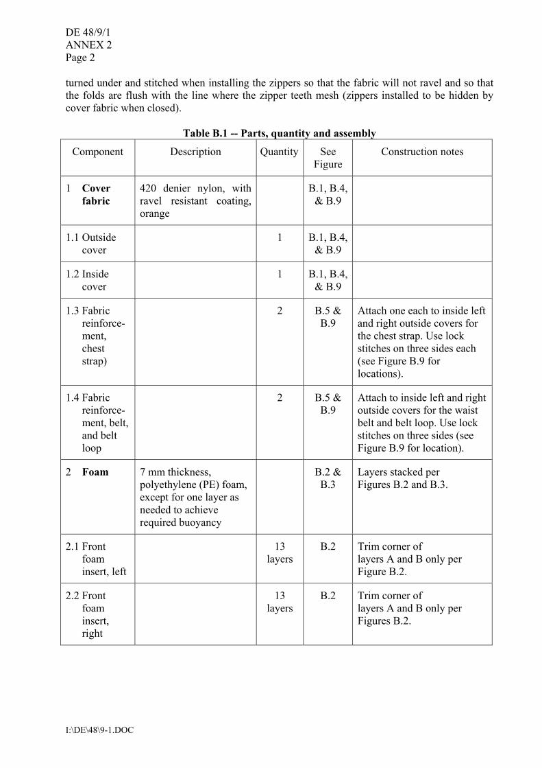
turned under and stitched when installing the zippers so that the fabric will not ravel and so that the folds are flush with the line where the zipper teeth mesh (zippers installed to be hidden by cover fabric when closed).
Table B.1 -- Parts, quantity and assembly
Component Description Quantity See Figure
Construction notes
1 Cover fabric
420 denier nylon, with ravel resistant coating, orange
B.1, B.4, & B.9
1.1 Outside cover
1 B.1, B.4, & B.9
1.2 Inside cover
1 B.1, B.4, & B.9
1.3 Fabric reinforce-ment, chest strap)
2 B.5 & B.9
Attach one each to inside left and right outside covers for the chest strap. Use lock stitches on three sides each (see Figure B.9 for locations).
1.4 Fabric reinforce-ment, belt, and belt loop
2 B.5 & B.9
Attach to inside left and right outside covers for the waist belt and belt loop. Use lock stitches on three sides (see Figure B.9 for location).
2 Foam 7 mm thickness, polyethylene (PE) foam, except for one layer as needed to achieve required buoyancy
B.2 & B.3
Layers stacked per Figures B.2 and B.3.
2.1 Front foam insert, left
13 layers
B.2 Trim corner of layers A and B only per Figure B.2.
2.2 Front foam insert, right
13 layers
B.2 Trim corner of layers A and B only per Figures B.2.
DE 48/9/1 ANNEX 2
Page 3
I:\DE\48\9-1.DOC
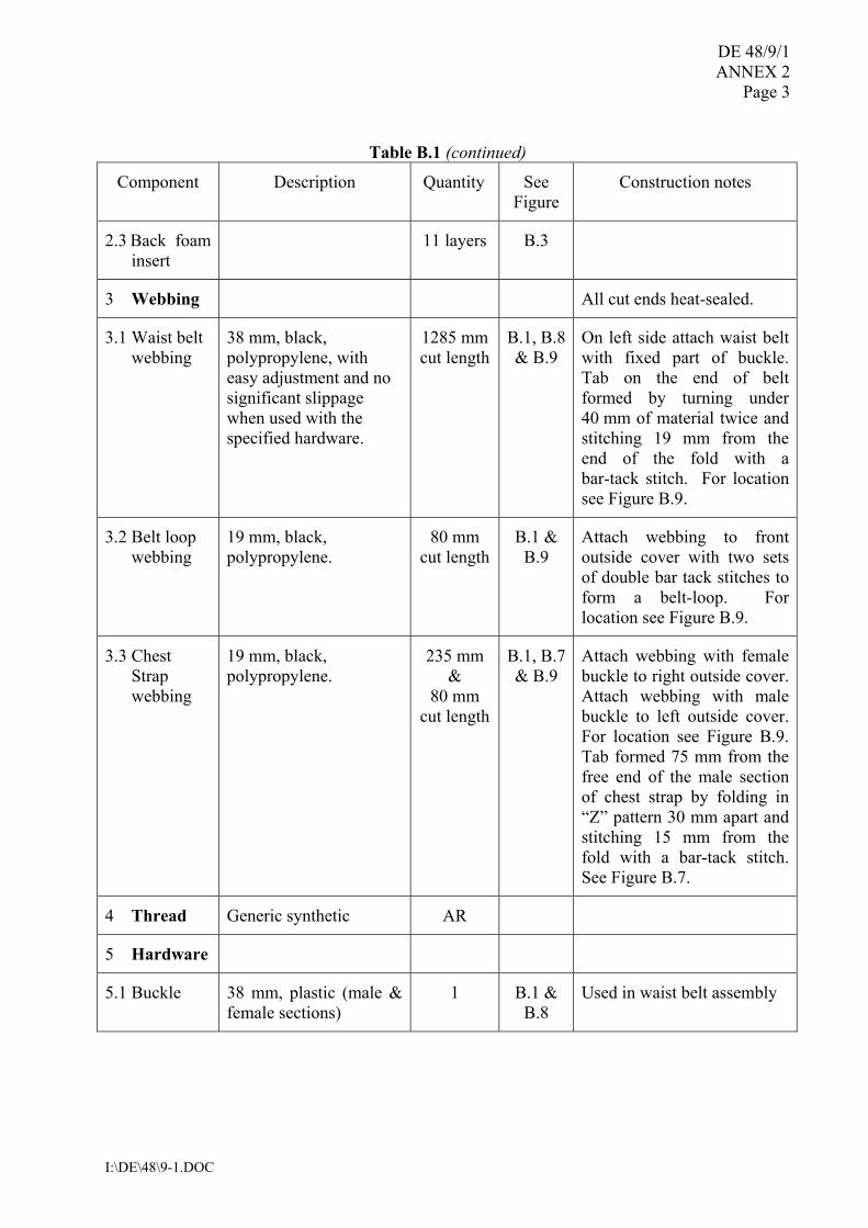
Table B.1 (continued)
Component Description Quantity See Figure
Construction notes
2.3 Back foam insert
11 layers B.3
3 Webbing All cut ends heat-sealed.
3.1 Waist belt webbing
38 mm, black, polypropylene, with easy adjustment and no significant slippage when used with the specified hardware.
1285 mm cut length
B.1, B.8 & B.9
On left side attach waist belt with fixed part of buckle. Tab on the end of belt formed by turning under 40 mm of material twice and stitching 19 mm from the end of the fold with a bar-tack stitch. For location see Figure B.9.
3.2 Belt loop webbing
19 mm, black, polypropylene.
80 mm cut length
B.1 & B.9
Attach webbing to front outside cover with two sets of double bar tack stitches to form a belt-loop. For location see Figure B.9.
3.3 Chest Strap webbing
19 mm, black, polypropylene.
235 mm &
80 mm cut length
B.1, B.7 & B.9
Attach webbing with female buckle to right outside cover. Attach webbing with male buckle to left outside cover. For location see Figure B.9. Tab formed 75 mm from the free end of the male section of chest strap by folding in �Z� pattern 30 mm apart and stitching 15 mm from the fold with a bar-tack stitch. See Figure B.7.
4 Thread Generic synthetic AR
5 Hardware
5.1 Buckle 38 mm, plastic (male & female sections)
1 B.1 & B.8
Used in waist belt assembly
DE 48/9/1 ANNEX 2 Page 4
I:\DE\48\9-1.DOC
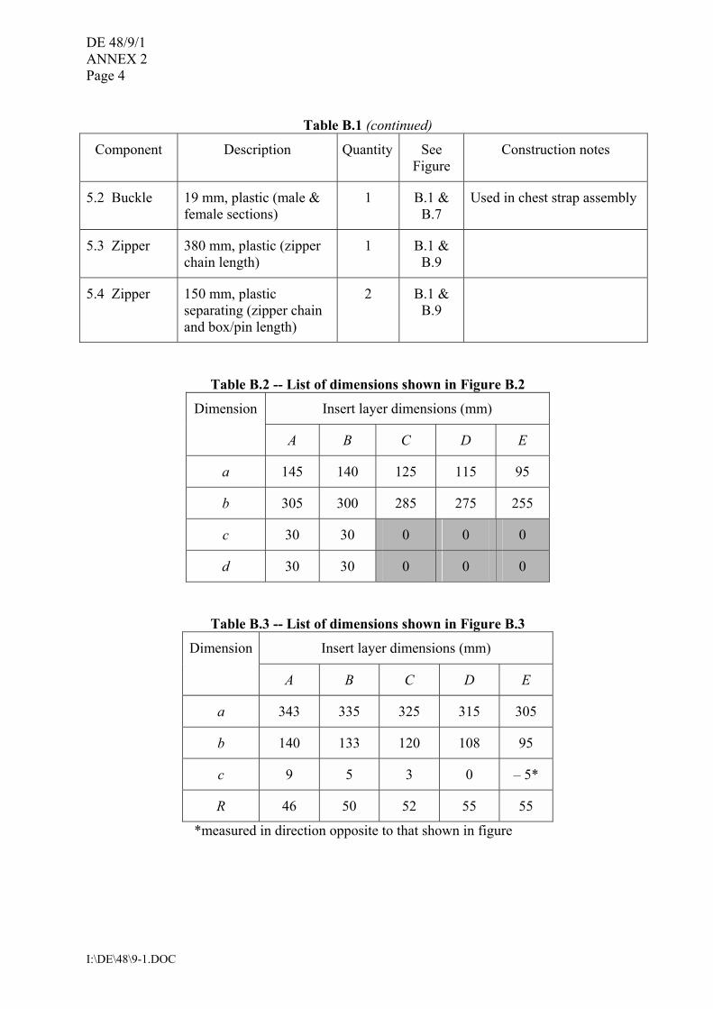
Table B.1 (continued)
Component Description Quantity See Figure
Construction notes
5.2 Buckle 19 mm, plastic (male & female sections)
1 B.1 & B.7
Used in chest strap assembly
5.3 Zipper 380 mm, plastic (zipper chain length)
1 B.1 & B.9
5.4 Zipper 150 mm, plastic separating (zipper chain and box/pin length)
2 B.1 & B.9
Table B.2 -- List of dimensions shown in Figure B.2
Insert layer dimensions (mm) Dimension
A B C D E
a 145 140 125 115 95
b 305 300 285 275 255
c 30 30 0 0 0
d 30 30 0 0 0
Table B.3 -- List of dimensions shown in Figure B.3
Insert layer dimensions (mm) Dimension
A B C D E
a 343 335 325 315 305
b 140 133 120 108 95
c 9 5 3 0 � 5*
R 46 50 52 55 55
*measured in direction opposite to that shown in figure
DE 48/9/1 ANNEX 2
Page 5
I:\DE\48\9-1.DOC
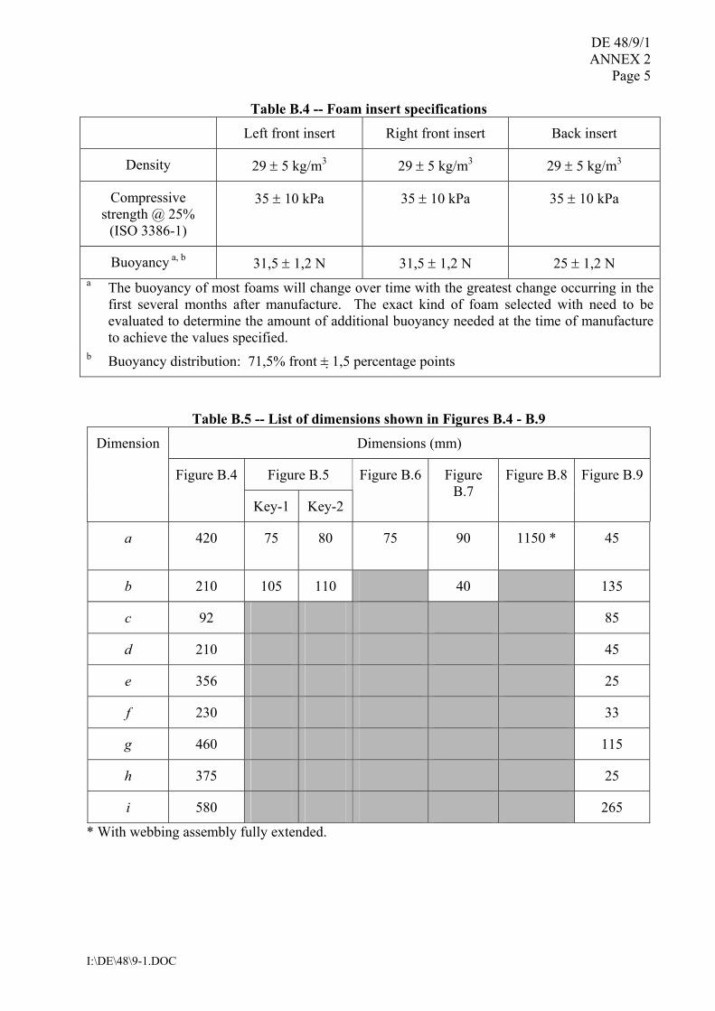
Table B.4 -- Foam insert specifications
Left front insert Right front insert Back insert
Density 29 ± 5 kg/m3 29 ± 5 kg/m3 29 ± 5 kg/m3
Compressive strength @ 25%
(ISO 3386-1)
35 ± 10 kPa 35 ± 10 kPa 35 ± 10 kPa
Buoyancy a, b 31,5 ± 1,2 N 31,5 ± 1,2 N 25 ± 1,2 N a The buoyancy of most foams will change over time with the greatest change occurring in the
first several months after manufacture. The exact kind of foam selected with need to be evaluated to determine the amount of additional buoyancy needed at the time of manufacture to achieve the values specified.
b Buoyancy distribution: 71,5% front ± 1,5 percentage points
Table B.5 -- List of dimensions shown in Figures B.4 - B.9
Dimensions (mm)
Figure B.5
Dimension
Figure B.4
Key-1 Key-2
Figure B.6 Figure B.7
Figure B.8 Figure B.9
a 420 75 80 75 90 1150 *
45
b 210 105 110 40 135
c 92 85
d 210 45
e 356 25
f 230 33
g 460 115
h 375 25
i 580 265
* With webbing assembly fully extended.
DE 48/9/1 ANNEX 2 Page 6
I:\DE\48\9-1.DOC
Left Right Outside (front) Inside
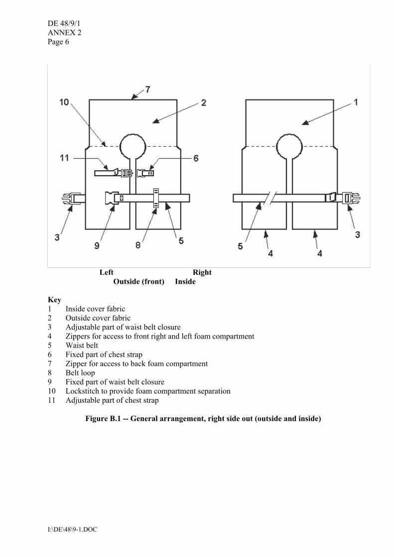
Key 1 Inside cover fabric 2 Outside cover fabric 3 Adjustable part of waist belt closure 4 Zippers for access to front right and left foam compartment 5 Waist belt 6 Fixed part of chest strap 7 Zipper for access to back foam compartment 8 Belt loop 9 Fixed part of waist belt closure 10 Lockstitch to provide foam compartment separation 11 Adjustable part of chest strap
Figure B.1 -- General arrangement, right side out (outside and inside)
DE 48/9/1 ANNEX 2
Page 7
I:\DE\48\9-1.DOC
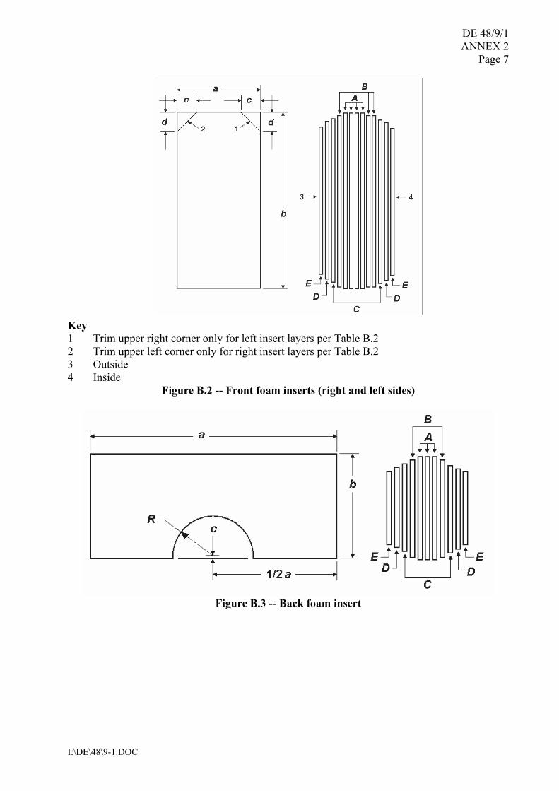
Key 1 Trim upper right corner only for left insert layers per Table B.2 2 Trim upper left corner only for right insert layers per Table B.2 3 Outside 4 Inside
Figure B.2 -- Front foam inserts (right and left sides)
Figure B.3 -- Back foam insert
DE 48/9/1 ANNEX 2 Page 8
I:\DE\48\9-1.DOC
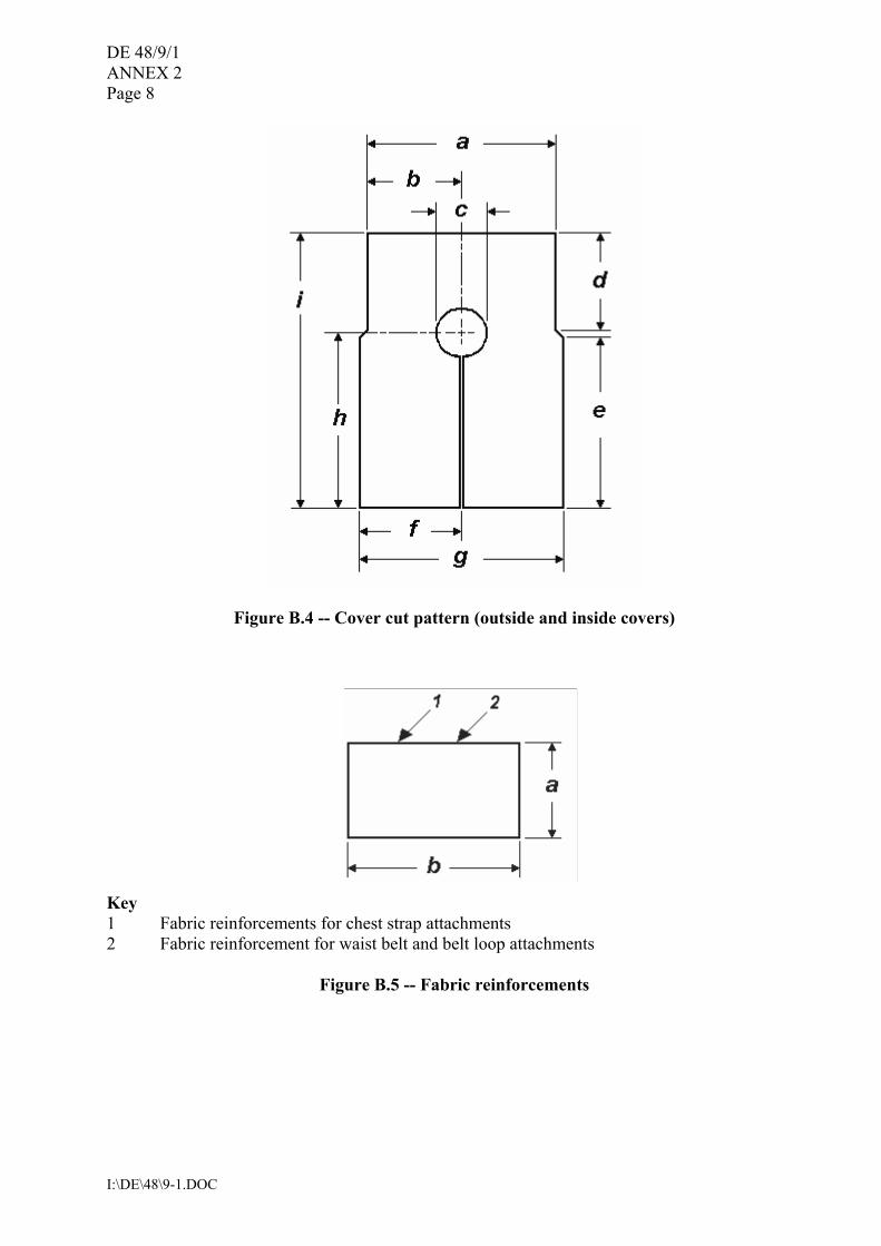
Figure B.4 -- Cover cut pattern (outside and inside covers)
Key 1 Fabric reinforcements for chest strap attachments 2 Fabric reinforcement for waist belt and belt loop attachments
Figure B.5 -- Fabric reinforcements
DE 48/9/1 ANNEX 2
Page 9
I:\DE\48\9-1.DOC
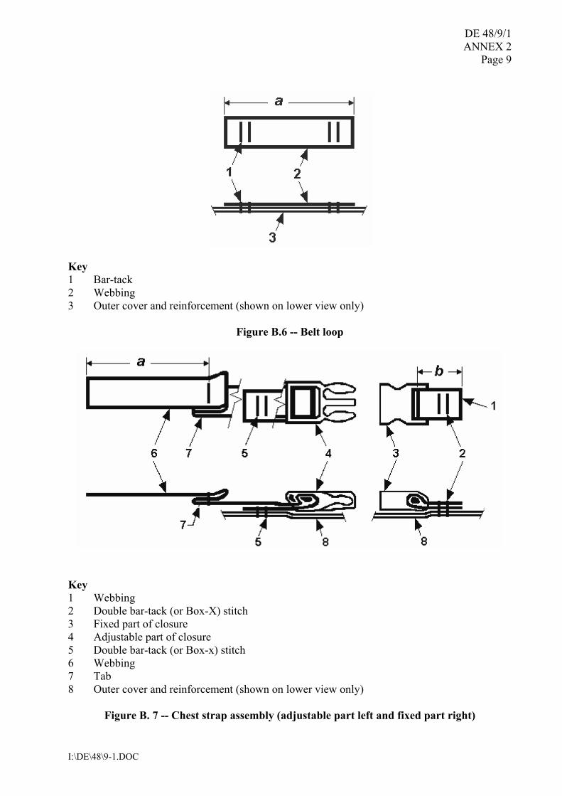
Key 1 Bar-tack 2 Webbing 3 Outer cover and reinforcement (shown on lower view only)
Figure B.6 -- Belt loop
Key 1 Webbing 2 Double bar-tack (or Box-X) stitch 3 Fixed part of closure 4 Adjustable part of closure 5 Double bar-tack (or Box-x) stitch 6 Webbing 7 Tab 8 Outer cover and reinforcement (shown on lower view only)
Figure B. 7 -- Chest strap assembly (adjustable part left and fixed part right)
DE 48/9/1 ANNEX 2 Page 10
I:\DE\48\9-1.DOC
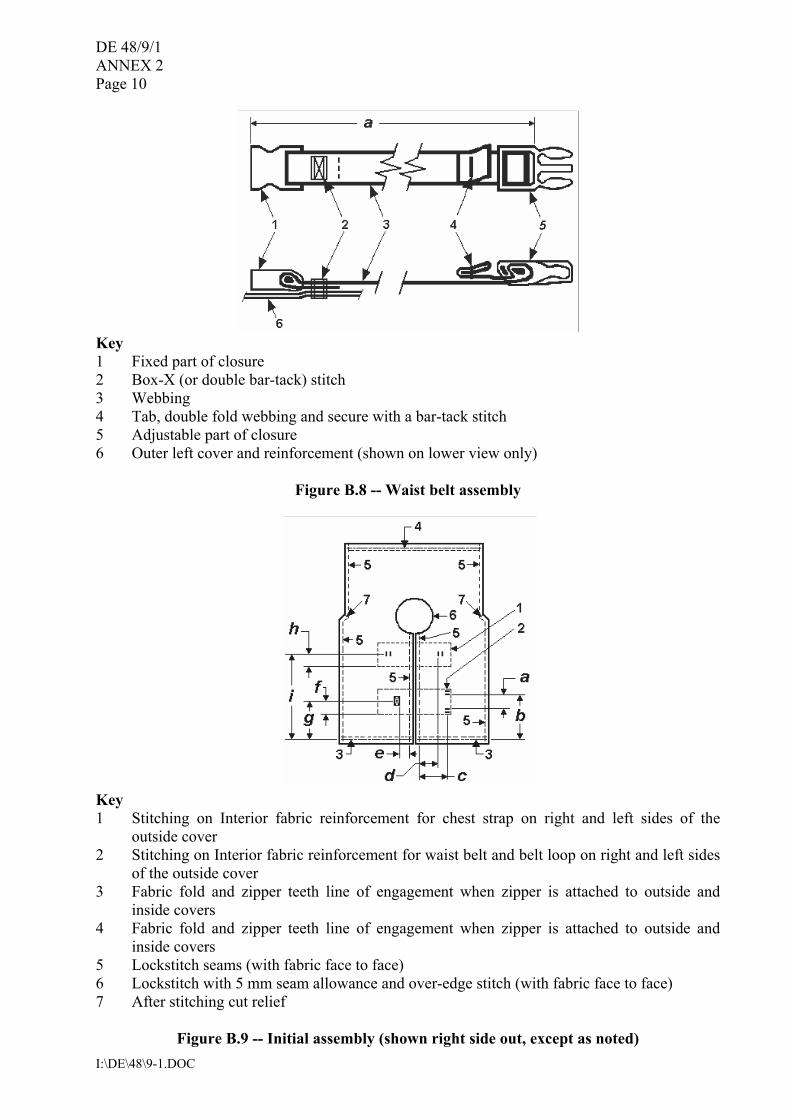
Key 1 Fixed part of closure 2 Box-X (or double bar-tack) stitch 3 Webbing 4 Tab, double fold webbing and secure with a bar-tack stitch 5 Adjustable part of closure 6 Outer left cover and reinforcement (shown on lower view only)
Figure B.8 -- Waist belt assembly
Key 1 Stitching on Interior fabric reinforcement for chest strap on right and left sides of the
outside cover 2 Stitching on Interior fabric reinforcement for waist belt and belt loop on right and left sides
of the outside cover 3 Fabric fold and zipper teeth line of engagement when zipper is attached to outside and
inside covers 4 Fabric fold and zipper teeth line of engagement when zipper is attached to outside and
inside covers 5 Lockstitch seams (with fabric face to face) 6 Lockstitch with 5 mm seam allowance and over-edge stitch (with fabric face to face) 7 After stitching cut relief
Figure B.9 -- Initial assembly (shown right side out, except as noted)
DE 48/9/1 ANNEX 2
Page 11
I:\DE\48\9-1.DOC
APPENDIX
RTD Serial number: ___________
CHILD REFERENCE TEST DEVICE � BUOYANCY TRACKING AND VERIFICATION
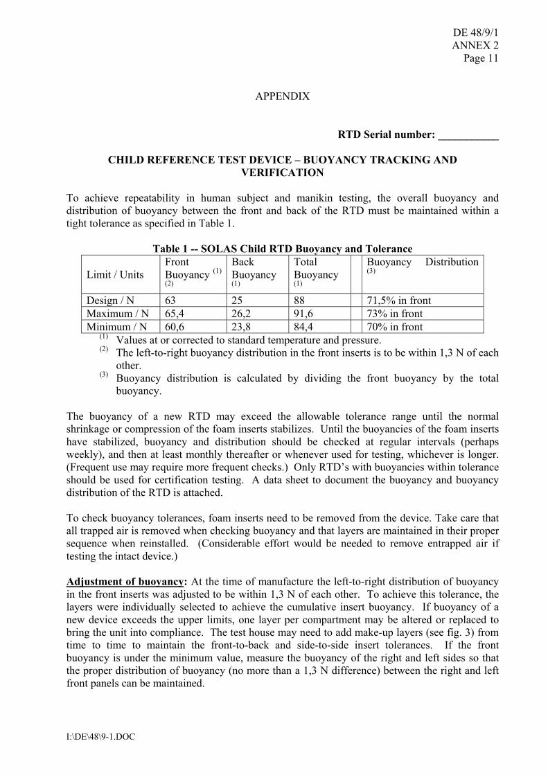
To achieve repeatability in human subject and manikin testing, the overall buoyancy and distribution of buoyancy between the front and back of the RTD must be maintained within a tight tolerance as specified in Table 1.
Table 1 -- SOLAS Child RTD Buoyancy and Tolerance
Limit / Units Front Buoyancy (1)
(2)
Back Buoyancy (1)
Total Buoyancy (1)
Buoyancy Distribution (3)
Design / N 63 25 88 71,5% in front Maximum / N 65,4 26,2 91,6 73% in front Minimum / N 60,6 23,8 84,4 70% in front
(1) Values at or corrected to standard temperature and pressure. (2) The left-to-right buoyancy distribution in the front inserts is to be within 1,3 N of each
other. (3) Buoyancy distribution is calculated by dividing the front buoyancy by the total
buoyancy. The buoyancy of a new RTD may exceed the allowable tolerance range until the normal shrinkage or compression of the foam inserts stabilizes. Until the buoyancies of the foam inserts have stabilized, buoyancy and distribution should be checked at regular intervals (perhaps weekly), and then at least monthly thereafter or whenever used for testing, whichever is longer. (Frequent use may require more frequent checks.) Only RTD�s with buoyancies within tolerance should be used for certification testing. A data sheet to document the buoyancy and buoyancy distribution of the RTD is attached. To check buoyancy tolerances, foam inserts need to be removed from the device. Take care that all trapped air is removed when checking buoyancy and that layers are maintained in their proper sequence when reinstalled. (Considerable effort would be needed to remove entrapped air if testing the intact device.) Adjustment of buoyancy: At the time of manufacture the left-to-right distribution of buoyancy in the front inserts was adjusted to be within 1,3 N of each other. To achieve this tolerance, the layers were individually selected to achieve the cumulative insert buoyancy. If buoyancy of a new device exceeds the upper limits, one layer per compartment may be altered or replaced to bring the unit into compliance. The test house may need to add make-up layers (see fig. 3) from time to time to maintain the front-to-back and side-to-side insert tolerances. If the front buoyancy is under the minimum value, measure the buoyancy of the right and left sides so that the proper distribution of buoyancy (no more than a 1,3 N difference) between the right and left front panels can be maintained.
DE 48/9/1 ANNEX 2 Page 12
I:\DE\48\9-1.DOC
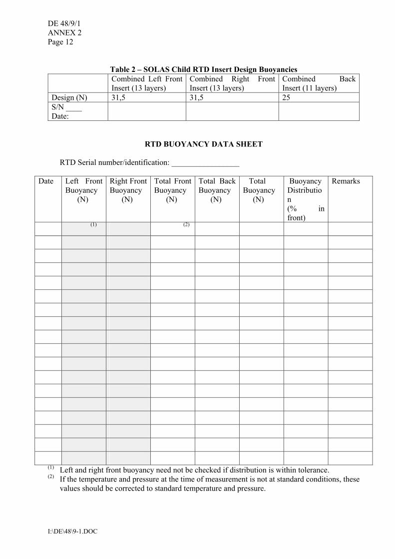
Table 2 � SOLAS Child RTD Insert Design Buoyancies
Combined Left Front Insert (13 layers)
Combined Right Front Insert (13 layers)
Combined BackInsert (11 layers)
Design (N) 31,5 31,5 25 S/N ____ Date:
RTD BUOYANCY DATA SHEET
RTD Serial number/identification: _________________
Date Left Front Buoyancy (N)
Right Front Buoyancy (N)
Total Front Buoyancy (N)
Total Back Buoyancy (N)
Total Buoyancy (N)
Buoyancy Distribution (% in front)
Remarks
(1) (2)
(1) Left and right front buoyancy need not be checked if distribution is within tolerance. (2) If the temperature and pressure at the time of measurement is not at standard conditions, these
values should be corrected to standard temperature and pressure.

DE 48/9/1 ANNEX 2
Page 13
I:\DE\48\9-1.DOC
Key 1 Trim upper right corner only for left insert layers A and B. 2 Trim upper left corner only for right insert layers A and B. 3 Outside 4 Inside
Insert layer
Insert layer dimensions (mm)
Buoyancy (approx.)
(N) a b c d A 2,8 145 305 30 30 B 2,7 140 300 30 30 C 2,3 125 285 0 0 D 2,0 115 275 0 0 E 1,6 95 255 0 0
Figure 1 � Front foam insert specifications
Insert layer Insert layer dimensions (mm)
Buoyancy (approx.)
(N) a b c R
A 2,8 343 140 9 46 B 2,6 335 133 5 50 C 2,2 325 120 3 52 D 1,9 315 108 0 55 E 1,6 305 95 -5* 55
*measured in direction opposite to that shown in figure
Figure 2 �Back foam insert specifications
DE 48/9/1 ANNEX 2 Page 14
I:\DE\48\9-1.DOC
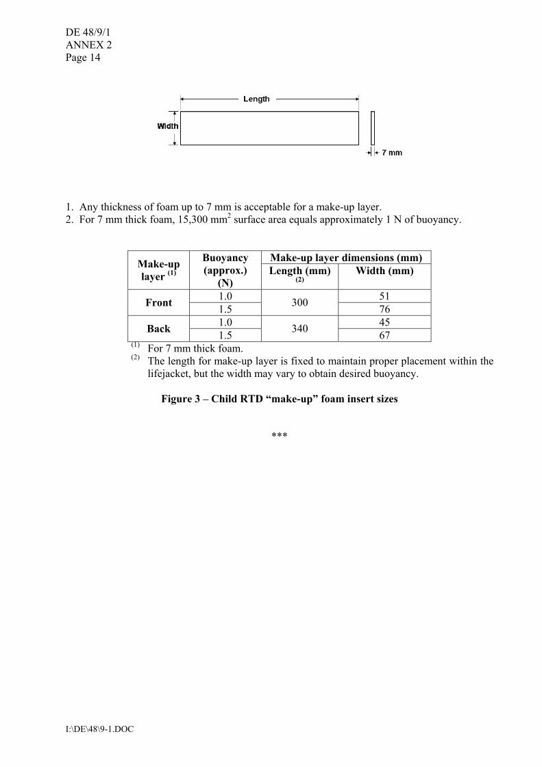
1. Any thickness of foam up to 7 mm is acceptable for a make-up layer. 2. For 7 mm thick foam, 15,300 mm2 surface area equals approximately 1 N of buoyancy.
Make-up layer dimensions (mm) Make-up layer (1)
Buoyancy (approx.)
(N) Length (mm)
(2) Width (mm)
1.0 51 Front 1.5 300 76 1.0 45 Back 1.5 340 67
(1) For 7 mm thick foam. (2) The length for make-up layer is fixed to maintain proper placement within the
lifejacket, but the width may vary to obtain desired buoyancy.
Figure 3 � Child RTD �make-up� foam insert sizes
***
DE 48/9/1
I:\DE\48\9-1.DOC
ANNEX 3
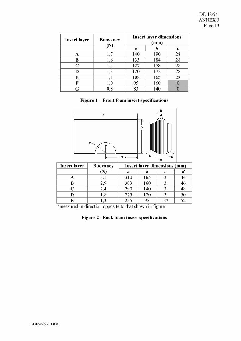
INFANT REFERENCE TEST DEVICE (RTD) DESIGN AND CONSTRUCTION
1 General. The infant RTD is for persons weighing less than 15 kg, or less than 100 cm in height. This RTD is made with layers of buoyant foam in a bib-style design using a heavy nylon shell cover fabric secured to the body with a waist belt with quick and positive closure and adjustment, along with a chest strap at the neck for closure and adjustment. The shell is made with slide fasteners (zippers) in place of closing seams to hold the foam within, in order that the foam inserts can be easily removed to check their buoyancy and renew or supplement them if they are out of tolerance. The device is designed to fit persons with a chest size of less than 50 cm. The RTD is designed to be reasonably comfortable to wear as a non-reversible device. 2 Materials. All materials used shall comply with ISO 12402-7. 2.1 Foam requirements. The performance of the RTD is dependent on using plastic foam of the proper stiffness, shapes, and buoyancy. 2.1.1 Stiffness. The buoyant inserts are made of layers of medium stiffness foam to create a flexible but firm buoyancy element. 2.1.2 Shape. The shape of each foam layer is identified in Figures C.2 and C.3. Dimensions are in Tables C.1, C.2 and C.3. 2.1.3 Buoyancy. The total design buoyancy of the device is 71 N. Table C.4 identifies foam characteristics, the buoyancy for each insert and its tolerances, and the overall buoyancy distribution to be verified when using the RTD for certification testing. 2.2 Other component requirements. See Table C.1. 3 Construction. The construction and assembly of the device shall be in accordance with Tables C.1 and C.5 and Figures C.1 through C.9. A tolerance of ± 6 mm is used throughout for fabric cutting and stitching assembly. A tolerance of ± 6 mm is also used for foam cutting, however, the buoyancy requirements of Table C.4 shall be met. 3.1 Seams. Seam allowances are 13 mm, unless otherwise specified. All structural seams use a lock type stitch so that the seam will not unravel when a force is applied in the direction of the seam on any of the threads forming the stitch. Stitching should have a density of 7 � 12 stitches per 25 mm of stitch length. Box-x stitching on the webbing is 30 x 15 mm for the waist belt and 15 x 13 mm for the belt loop and chest strap, unless otherwise specified. The bar-tack stitching on webbing is 30 x 2 mm for the waist belt and 15 x 2 mm for the belt loop and chest strap. 3.1.1 The fabric reinforcements for the waist belt, belt loop, and chest strap should be attached to the inside surface of the outside cover before attaching any of these items. On the closing seam of the top and bottom sections of the outside and inside cover, the cut ends of the fabric are
DE 48/9/1 ANNEX 3 Page 2
I:\DE\48\9-1.DOC
turned under and stitched when installing the zippers so that the fabric will not ravel and so that the folds are flush with the line where the zipper teeth mesh (zippers installed to be hidden by cover fabric when closed).
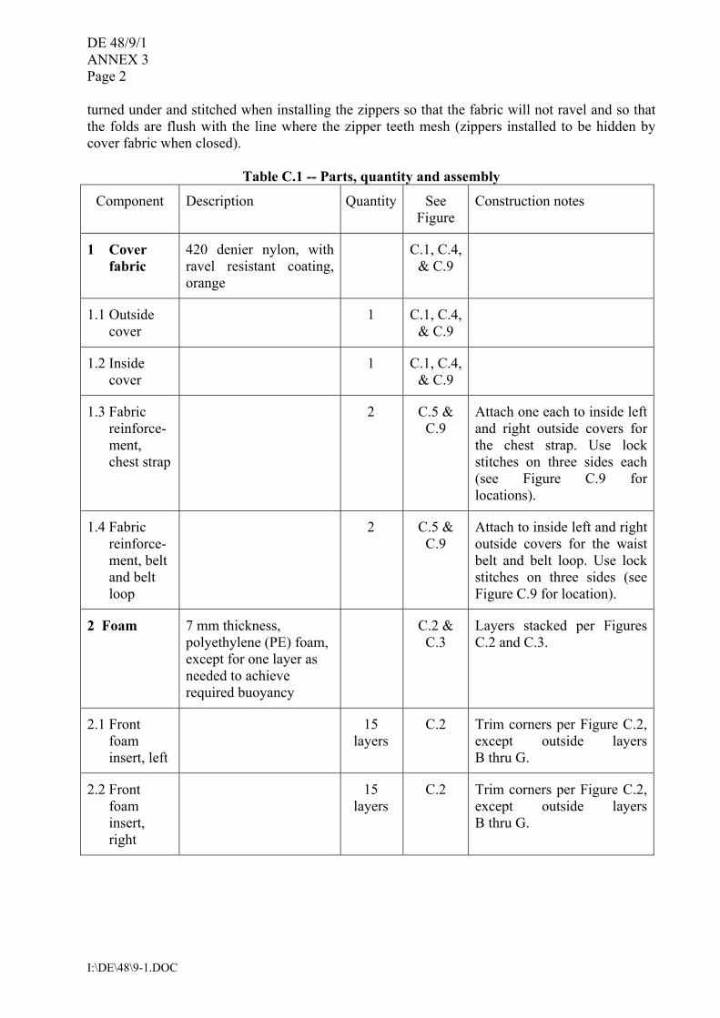
Table C.1 -- Parts, quantity and assembly
Component Description Quantity See Figure
Construction notes
1 Cover fabric
420 denier nylon, with ravel resistant coating, orange
C.1, C.4, & C.9
1.1 Outside cover
1 C.1, C.4, & C.9
1.2 Inside cover
1 C.1, C.4, & C.9
1.3 Fabric reinforce-ment, chest strap
2 C.5 & C.9
Attach one each to inside left and right outside covers for the chest strap. Use lock stitches on three sides each (see Figure C.9 for locations).
1.4 Fabric reinforce-ment, belt and belt loop
2 C.5 & C.9
Attach to inside left and right outside covers for the waist belt and belt loop. Use lock stitches on three sides (see Figure C.9 for location).
2 Foam 7 mm thickness, polyethylene (PE) foam, except for one layer as needed to achieve required buoyancy
C.2 & C.3
Layers stacked per Figures C.2 and C.3.
2.1 Front foam insert, left
15 layers
C.2 Trim corners per Figure C.2, except outside layers B thru G.
2.2 Front foam insert, right
15 layers
C.2 Trim corners per Figure C.2, except outside layers B thru G.
DE 48/9/1 ANNEX 3
Page 3
I:\DE\48\9-1.DOC
Table C.1 (continued)
Component Description Quantity See Figure
Construction notes
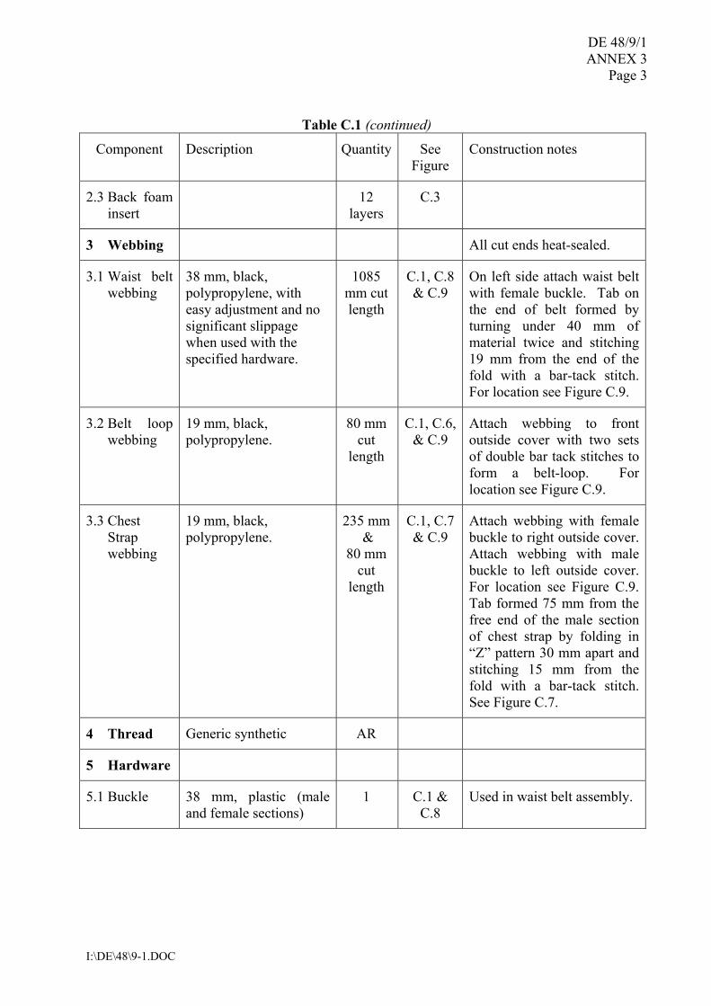
2.3 Back foam insert
12 layers
C.3
3 Webbing All cut ends heat-sealed.
3.1 Waist belt webbing
38 mm, black, polypropylene, with easy adjustment and no significant slippage when used with the specified hardware.
1085 mm cut length
C.1, C.8 & C.9
On left side attach waist belt with female buckle. Tab on the end of belt formed by turning under 40 mm of material twice and stitching 19 mm from the end of the fold with a bar-tack stitch. For location see Figure C.9.
3.2 Belt loop webbing
19 mm, black, polypropylene.
80 mm cut
length
C.1, C.6, & C.9
Attach webbing to front outside cover with two sets of double bar tack stitches to form a belt-loop. For location see Figure C.9.
3.3 Chest Strap webbing
19 mm, black, polypropylene.
235 mm &
80 mm cut
length
C.1, C.7 & C.9
Attach webbing with female buckle to right outside cover. Attach webbing with male buckle to left outside cover. For location see Figure C.9. Tab formed 75 mm from the free end of the male section of chest strap by folding in �Z� pattern 30 mm apart and stitching 15 mm from the fold with a bar-tack stitch. See Figure C.7.
4 Thread Generic synthetic AR
5 Hardware
5.1 Buckle 38 mm, plastic (male and female sections)
1 C.1 & C.8
Used in waist belt assembly.
DE 48/9/1 ANNEX 3 Page 4
I:\DE\48\9-1.DOC
Table C.1 (continued)
Component Description Quantity See Figure
Construction notes
5.2 Buckle 19 mm, plastic (male and female sections)
1 C.1 & C.7
Used in chest strap assembly
5.3 Zipper 350 mm, plastic (zipper chain length)
1 C.1 & C.9
Installed to be hidden by cover fabric when closed.
5.4 Zipper 180 mm, plastic separating (zipper chain and box/pin length)
2 C.1 & C.9
Installed to be hidden by cover fabric when closed.
Table C.2 -- List of dimensions shown in Figure C.2
Insert layer dimensions (mm) Dimension
A B C D E F G
a 140 133 127 120 108 95 83
b 190 184 178 172 165 160 140
c 28 28 28 28 28
Table C.3-- List of dimensions shown in Figure C.3
Insert layer dimensions (mm) Dimension
A B C D E
a 310 303 290 275 255
b 165 160 140 120 95
c 3 3 3 3 � 3*
R 44 44 44 44 44
*measured in direction opposite to that shown in figure
DE 48/9/1 ANNEX 3
Page 5
I:\DE\48\9-1.DOC
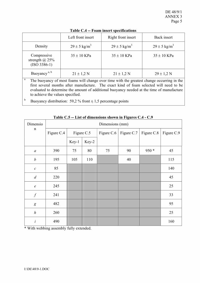
Table C.4 -- Foam insert specifications
Left front insert Right front insert Back insert
Density 29 ± 5 kg/m3 29 ± 5 kg/m3 29 ± 5 kg/m3
Compressive strength @ 25%
(ISO 3386-1)
35 ± 10 KPa 35 ± 10 KPa 35 ± 10 KPa
Buoyancy a, b 21 ± 1,2 N 21 ± 1,2 N 29 ± 1,2 N a The buoyancy of most foams will change over time with the greatest change occurring in the
first several months after manufacture. The exact kind of foam selected will need to be evaluated to determine the amount of additional buoyancy needed at the time of manufacture to achieve the values specified.
b Buoyancy distribution: 59,2 % front ± 1,5 percentage points
Table C.5 -- List of dimensions shown in Figures C.4 - C.9
Dimensions (mm)
Figure C.5
Dimension
Figure C.4
Key-1 Key-2
Figure C.6 Figure C.7 Figure C.8 Figure C.9
a 390 75 80 75 90 950 * 45
b 195 105 110 40 115
c 85 140
d 220 45
e 245 25
f 241 33
g 482 95
h 260 25
i 490 160
* With webbing assembly fully extended.
DE 48/9/1 ANNEX 3 Page 6
I:\DE\48\9-1.DOC
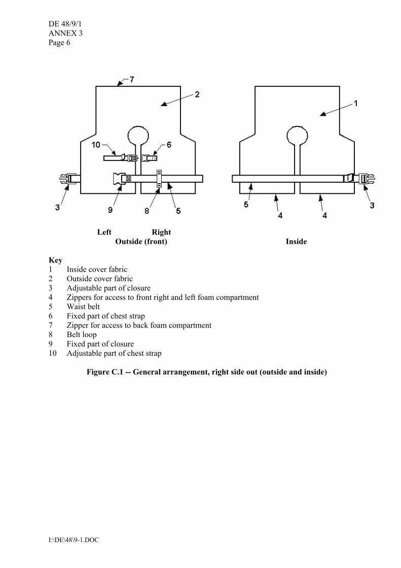
Left Right Outside (front) Inside
Key 1 Inside cover fabric 2 Outside cover fabric 3 Adjustable part of closure 4 Zippers for access to front right and left foam compartment 5 Waist belt 6 Fixed part of chest strap 7 Zipper for access to back foam compartment 8 Belt loop 9 Fixed part of closure 10 Adjustable part of chest strap
Figure C.1 -- General arrangement, right side out (outside and inside)
DE 48/9/1 ANNEX 3
Page 7
I:\DE\48\9-1.DOC
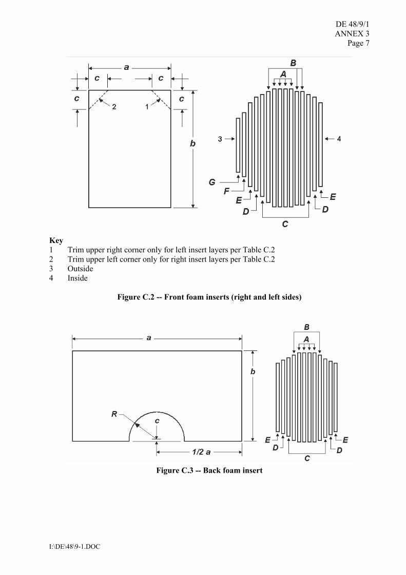
Key 1 Trim upper right corner only for left insert layers per Table C.2 2 Trim upper left corner only for right insert layers per Table C.2 3 Outside 4 Inside
Figure C.2 -- Front foam inserts (right and left sides)
Figure C.3 -- Back foam insert
DE 48/9/1 ANNEX 3 Page 8
I:\DE\48\9-1.DOC
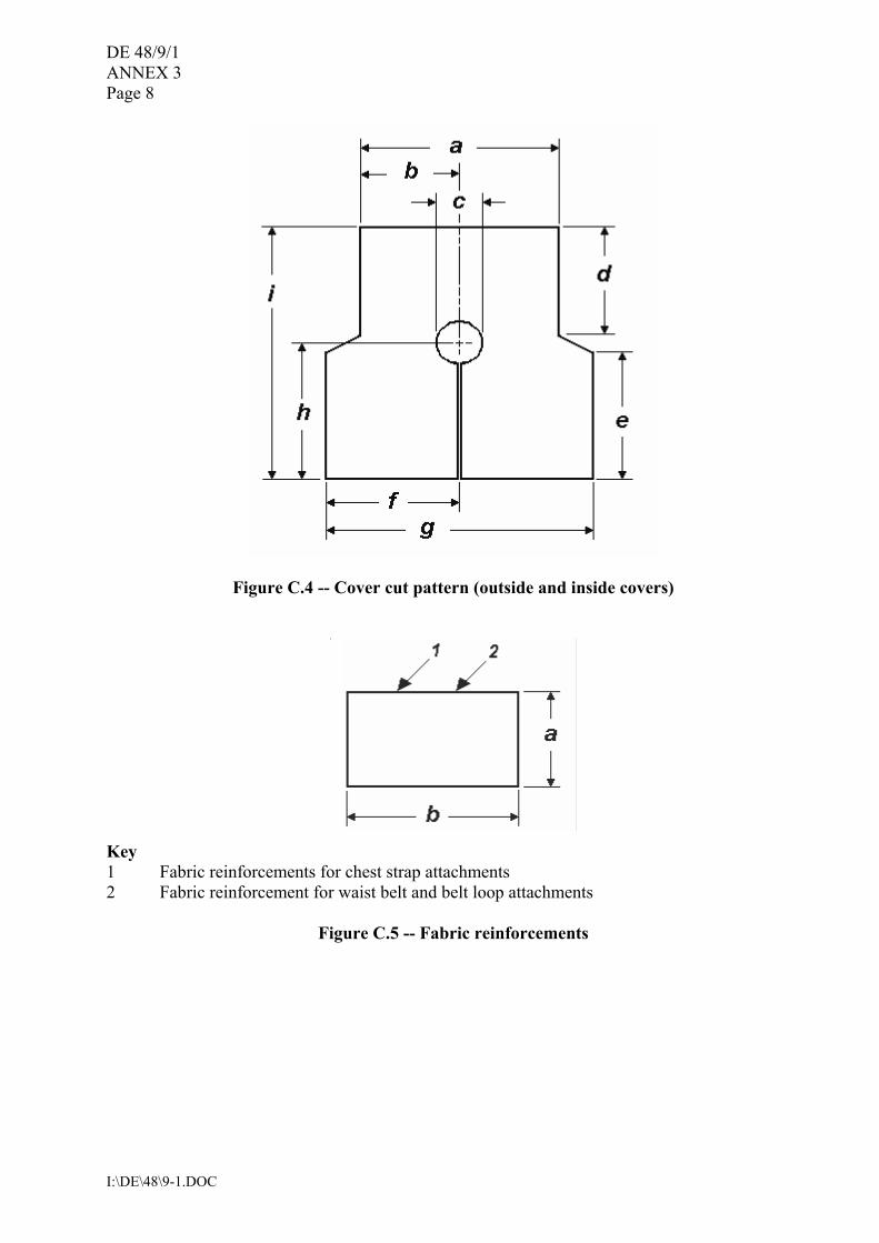
Figure C.4 -- Cover cut pattern (outside and inside covers)
Key 1 Fabric reinforcements for chest strap attachments 2 Fabric reinforcement for waist belt and belt loop attachments
Figure C.5 -- Fabric reinforcements
DE 48/9/1 ANNEX 3
Page 9
I:\DE\48\9-1.DOC
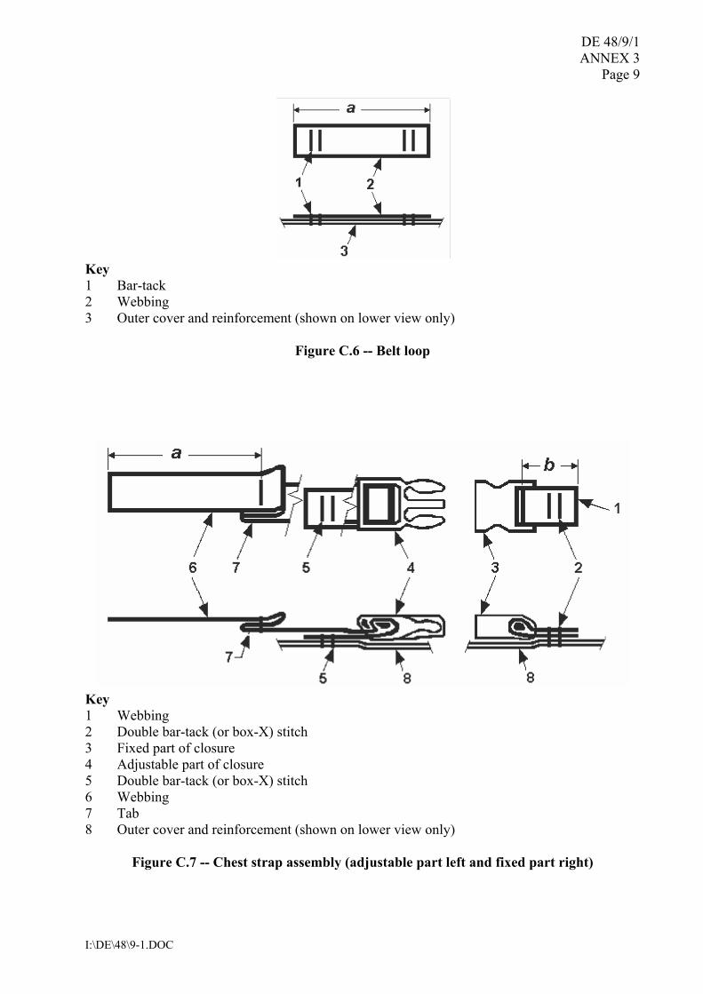
Key 1 Bar-tack 2 Webbing 3 Outer cover and reinforcement (shown on lower view only)
Figure C.6 -- Belt loop
Key 1 Webbing 2 Double bar-tack (or box-X) stitch 3 Fixed part of closure 4 Adjustable part of closure 5 Double bar-tack (or box-X) stitch 6 Webbing 7 Tab 8 Outer cover and reinforcement (shown on lower view only)
Figure C.7 -- Chest strap assembly (adjustable part left and fixed part right)
DE 48/9/1 ANNEX 3 Page 10
I:\DE\48\9-1.DOC
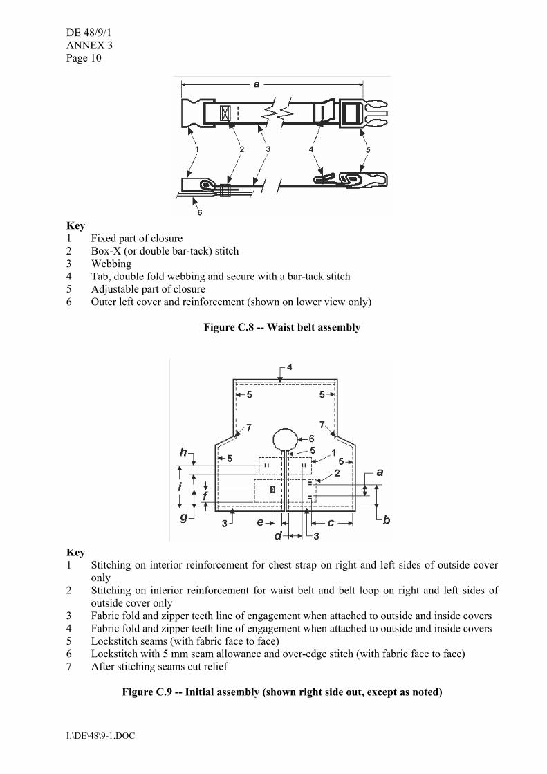
Key 1 Fixed part of closure 2 Box-X (or double bar-tack) stitch 3 Webbing 4 Tab, double fold webbing and secure with a bar-tack stitch 5 Adjustable part of closure 6 Outer left cover and reinforcement (shown on lower view only)
Figure C.8 -- Waist belt assembly
Key 1 Stitching on interior reinforcement for chest strap on right and left sides of outside cover
only 2 Stitching on interior reinforcement for waist belt and belt loop on right and left sides of
outside cover only 3 Fabric fold and zipper teeth line of engagement when attached to outside and inside covers 4 Fabric fold and zipper teeth line of engagement when attached to outside and inside covers 5 Lockstitch seams (with fabric face to face) 6 Lockstitch with 5 mm seam allowance and over-edge stitch (with fabric face to face) 7 After stitching seams cut relief
Figure C.9 -- Initial assembly (shown right side out, except as noted)
DE 48/9/1 ANNEX 3
Page 11
I:\DE\48\9-1.DOC
APPENDIX
RTD Serial number: ___________
INFANT REFERENCE TEST DEVICE � BUOYANCY TRACKING AND
VERIFICATION
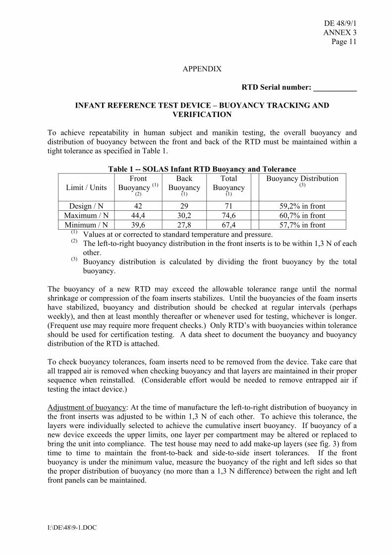
To achieve repeatability in human subject and manikin testing, the overall buoyancy and distribution of buoyancy between the front and back of the RTD must be maintained within a tight tolerance as specified in Table 1.
Table 1 -- SOLAS Infant RTD Buoyancy and Tolerance
Limit / Units Front
Buoyancy (1)
(2)
Back Buoyancy
(1)
Total Buoyancy
(1)
Buoyancy Distribution (3)
Design / N 42 29 71 59,2% in front Maximum / N 44,4 30,2 74,6 60,7% in front Minimum / N 39,6 27,8 67,4 57,7% in front
(1) Values at or corrected to standard temperature and pressure. (2) The left-to-right buoyancy distribution in the front inserts is to be within 1,3 N of each
other. (3) Buoyancy distribution is calculated by dividing the front buoyancy by the total
buoyancy.
The buoyancy of a new RTD may exceed the allowable tolerance range until the normal shrinkage or compression of the foam inserts stabilizes. Until the buoyancies of the foam inserts have stabilized, buoyancy and distribution should be checked at regular intervals (perhaps weekly), and then at least monthly thereafter or whenever used for testing, whichever is longer. (Frequent use may require more frequent checks.) Only RTD�s with buoyancies within tolerance should be used for certification testing. A data sheet to document the buoyancy and buoyancy distribution of the RTD is attached. To check buoyancy tolerances, foam inserts need to be removed from the device. Take care that all trapped air is removed when checking buoyancy and that layers are maintained in their proper sequence when reinstalled. (Considerable effort would be needed to remove entrapped air if testing the intact device.) Adjustment of buoyancy: At the time of manufacture the left-to-right distribution of buoyancy in the front inserts was adjusted to be within 1,3 N of each other. To achieve this tolerance, the layers were individually selected to achieve the cumulative insert buoyancy. If buoyancy of a new device exceeds the upper limits, one layer per compartment may be altered or replaced to bring the unit into compliance. The test house may need to add make-up layers (see fig. 3) from time to time to maintain the front-to-back and side-to-side insert tolerances. If the front buoyancy is under the minimum value, measure the buoyancy of the right and left sides so that the proper distribution of buoyancy (no more than a 1,3 N difference) between the right and left front panels can be maintained.
DE 48/9/1 ANNEX 3 Page 12
I:\DE\48\9-1.DOC
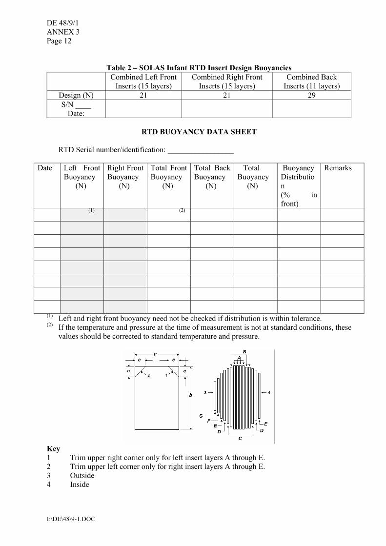
Table 2 � SOLAS Infant RTD Insert Design Buoyancies
Combined Left Front Inserts (15 layers)
Combined Right Front Inserts (15 layers)
Combined Back Inserts (11 layers)
Design (N) 21 21 29 S/N ____
Date:
RTD BUOYANCY DATA SHEET
RTD Serial number/identification: _________________
Date Left Front
Buoyancy (N)
Right Front Buoyancy (N)
Total Front Buoyancy (N)
Total Back Buoyancy (N)
Total Buoyancy (N)
Buoyancy Distribution (% in front)
Remarks
(1) (2)
(1) Left and right front buoyancy need not be checked if distribution is within tolerance. (2) If the temperature and pressure at the time of measurement is not at standard conditions, these
values should be corrected to standard temperature and pressure.
Key 1 Trim upper right corner only for left insert layers A through E. 2 Trim upper left corner only for right insert layers A through E. 3 Outside 4 Inside
DE 48/9/1 ANNEX 3
Page 13
I:\DE\48\9-1.DOC
Insert layer Insert layer dimensions (mm)
Buoyancy (N) a b c
A 1,7 140 190 28 B 1,6 133 184 28 C 1,4 127 178 28 D 1,3 120 172 28 E 1,1 108 165 28 F 1,0 95 160 0 G 0,8 83 140 0
Figure 1 � Front foam insert specifications
Insert layer Insert layer dimensions (mm)
Buoyancy
(N) a b c R A 3,1 310 165 3 44 B 2,9 303 160 3 46 C 2,4 290 140 3 48 D 1,8 275 120 3 50 E 1,3 255 95 -3* 52
*measured in direction opposite to that shown in figure
Figure 2 �Back foam insert specifications

DE 48/9/1 ANNEX 3 Page 14
I:\DE\48\9-1.DOC
1. Any thickness of foam up to 7 mm is acceptable for a make-up layer. 2. For 7 mm thick foam, 15,300 mm2 surface area equals approximately 1 N of buoyancy.
Make-up layer dimensions (mm) Make-up layer (1)
Buoyancy (approx.)
(N) Length (mm)
(2) Width (mm)
1.0 82 Front 1.5 185 123 1.0 50 Back 1.5 305 75
(1) For 7 mm thick foam. (2) The length for make-up layer is fixed to maintain proper placement within the
lifejacket, but the width may vary to obtain desired buoyancy.
Figure 3 � Child RTD �make-up� foam insert sizes
___________


![Iftikhar et al., Textile Sci Eng 2018, 8:3 e 10.4172/2165 ... · are four classes of seams such as; superimposed seam, lapped seam, bound seam and flat seam [9]. Durability of clothing](https://img.pdfslide.us/doc/110x75/5e98baf098727a3607054248/iftikhar-et-al-textile-sci-eng-2018-83-e-1041722165-are-four-classes-of.jpg)