Embed Size (px)
Citation preview

PERFORMANCE TEST PLAN
A SPACE STATION TOLUENE HEATER TUBE FOR
CONTRACT NO. 9-X6H-8102L-l
PREPARED FOR LOS ALAMOS NATIONAL LABORATORY
LOS ALAMOS, NEW MEXICO
BY SUNDSTRAND ENERGY SYSTEMS
4747 HARRISON AVENUE ROCKFORD, ILLINOIS
OCTOBER 1, 1987

DISCLAIMER
This report was prepared as an account of work sponsored by an agency of the United States Government. Neither the United States Government nor any agency thereof, nor any of their employees, makes any warranty, express or implied, or assumes any legal liability or responsibility for the accuracy, completeness, or use- fulncss of any information, apparatus, product, or process disclosed, or represents. that its use would not infringe privately owned rights. Reference herein to any spe- cific commercial product, proctss, or service by trade name. trademark, manufac- turer, or otherwise docs not necessarily constitute or imply its endorsement, ream- mendation, or favoring by the United States Government or any agency thereof. The views and opinions of authors expressed herein do not necessarily state or reflect those of the United States Government or any agency thereof.

.
DISCLAIMER
Portions of this document may be illegible electronic image products. Images are produced from the best available original document.

PREPARED BY
APPROVED BY
APPROVAL SHEET
PERFORMANCE TEST PLAN FOR
A SPACE STATION TOLUENE HEATER TUBE (CONTRACT NO: 9-X6H-8102L-l)
,---
APPROVED BY
DATE / 0 - / Y - $ Y

,
PERFORMANCE TEST PLAN FOR
A SPACE STATION TOLUENE HEATER TUBE
TABLE OF CONTENTS
PAGE - DESCRIPTION
1.0 Introduction 1
Technical Objectives 3 2.0
4 Design Requirements 3.0
Test Loop and Hardware Description 4.0
4.1 Test Loop Description'
4.2 Toluene Heater Tube
5.0 Performance Predictions 8
6.0 Planned tests 9
10 Procedures 7.0 c

8.0
9.0
Data Acquisition System
Report
12
13
c

Performance Test an for a! Space Station Toluene Heater Tube'
1.0 Introduction
This test plan describes the Sundstrand portion of Task
4 of Los Alamos National Laboratory (LANL) contract
Sundstrand Energy Systems was awarded a contract to
investigate the performance capabilities of a.toluene
heater tube integral to a heat pipe as applied to the
Organic Rankine Cycle (ORC) solar dynamic power system
for the Space Station.
This heat pipe is a subassembly of the heat receiver
shown in Figure 1. The heat receiver, the heat
absorption component of the ORC solar dynamic power
system, consists of forty liquid metal heat pipes located
circumferentially around the heat receiver s outside
diameter. As shown in Figure 1, each heat pipe contains
a toluene heater tube, two thermal energy storage (TES)
canisters and potassium.
c
1

Performance Test Plan for a Space Station To: ne Heatef Tube
The function of the heater tube is to heat the
supercritical toluene to the required turbine inlet
temperature.
heat receiver and thereby the heat pipe and heater tube
will be subjected to variable heat input.
the heater must be such that it can accommodate the
thermal and hydraulic variations that will be imposed
upon it.
During the orbit of the space station, the
The design of
c
2

Performance Test ='.an for a Space Station Toi ,?e Heate?? Tube
2.0 Technical Objectives
The following represent the technical objectives for
Task 4: I
o To determine the hydraulic and thermal performance
characteristics of the toluene heater. tube (THT)
with heat input simulating that from a heat pipe.
o To verify the design techniques used to predict the
thermal performance characteristics of the heater
tube. The following two space station conditions
are planned to be simulated:
a. Maximum input power
b. Minimum input power
c
3

Performance Test -'an for a Space Station To1 ne Heater Tube
-3.0 Design Requirements
The following
loop and test
form the basis for the design of the test
hardware:
0
0
0
0
0
0
0
Simulate thermal and hydraulic aspects of the
space station heater tube (Described in section
5.0)
Maximum input power to the working fluid 3.85
KWt Toluene working fluid (Conditions defined in
Table 111)
Constant f l o w rate for all conditions (54.35
lbm/hr for maximum power and 39.25 lbm/hr for
minimum power )
Supercritical cycle
Fluidized bed as,a heat source to simulate
isothermal heat input to heater tube
Detailed cleaning and purging procedures
similar to that used under the NAS3-24663
Toluene Stability Program
c
4

Performance Test sn for a , Space Station Tol,,ne Heater Tube.
4.0
4.1
c
Test Loop and Hardware Description
Descriptions are given for the test loop and test
.
hardware in this section.
Test Loop Description
The toluene heater tube (THT) thermal and hydraulic
performance tests will be conducted in Sundstrand test
cell 62 using the toluene stability loop Which is
specifically modified for these tests. The toluene
stability test loop was originally designed and built
under the separate government funded program (NAS3-24663)
for the measurement of toluene degradation rate while
simulating the ORC turbine inlet/outlet conditions.
Figure 2 shows the modified toluene test facility
schematic for testing the toluene heater tube. Test loop
cleaning and toluene handling procedures are briefly
described in Paragraph 7.0.
will be adjusted to the desired value by the control
valve shown on Figure 2. The toluene inlet temperature
will be controlled by adjusting the heat rejected in the
water cooled condenser. This is done with valve VI shown
on Figure 2. The temperature of fluidized bed, which is a heat source for this test, will be maintained at the
desired value by controlling the power input to the
electrical heaters. Figure 3 shows the test article
submerged in the fluidized bed. General engineering
features of the fluidized bed are shown in Figure 4.
The toluene inlet mass flow
5

Performance Test an for a; Space Station ToLdne Heater Tube
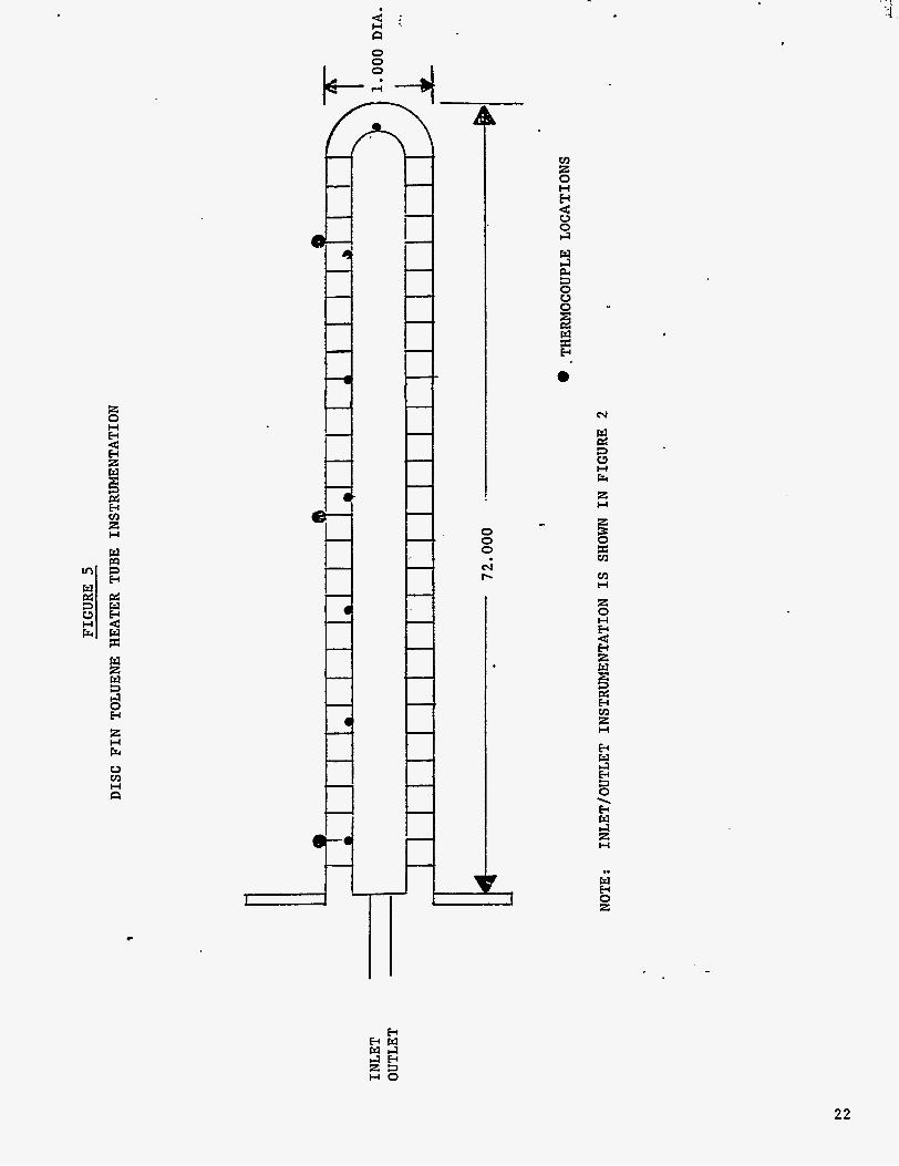
Instrumentation (as listed in Table I) will be provided
to measure the inlet mass flow, pressure and temperature
for the toluene heater tube. The outlet temperature and
the pressure drop across the toluene heater tube inlet
and outlet ports will also be measured.
thermocouples will be located on the thermal stand-off
sections of the heater tube.
temperature and the heater tube external skin temperature
will be monitored. Figures 2 and 5 show the pressure and
temperature probe locations.
acquisition system will be used to monitor and record the
test data. The red line parameters will also be
identified to shut down the test system in case of the
system operating beyond a safe limit.
be automatic and/or manual. Table I describes the
instrumentation that willsbe used to monitor the thermal
performance of the toluene heater tube.
Additional
The fluidized bed
An automatic computer data
The shutdown may
4.2 Toluene Heater Tube
c
The organic Rankine cycle solar dynamic power system
(ORC-SDPS) converts concentrated solar energy into the
thermal energy required to generate electric power. Heat,
pipes, with integral thermal energy storage canisters and
6
Performance Test In for a ; Space Station ToluGne Heater Tube
c
heater tubes, form the cavity inside wall of the solar
receiver. They absorb solar energy and transform it into
a uniform source temperature for the ORC working fluid
(toluene). The bayonet style toluene heater tube (THT),
integral to the heat pipe, provides an interface between
the heat pipe potassium vapor and the toluene working
fluid.
toluene temperature increase throughout tkie heater tube
length, thereby minimizing toluene degradation for a
given outlet temperature.
A constant heat flux THT design ensures a gradual
Constant heat flux to the toluene working fluid from a
uniform source temperature can be accomplished by
incorporating thermal standoffs in the THT design.
such design provides disk fins with axially varying
cross-section as the thermal standoffs between the heat
pipe/heater tube interface (outer tube) and the inner
toluene working fluid tube (inner tube).
standoffs with radially low conductance at the toluene
annulus inlet linearly increasing to radially high
conductance at the toluene annulus exit provide an
axially uniform heat flux to the toluene.
One
Thermal
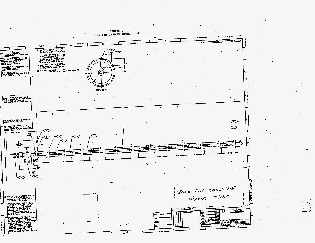
The disk fin constant heat flux heater tube developed and
fabricated under Los Alamos contract no. 9-X6H-8102L-1,
shown in Figure 6.
300 series stainless steel, which is compatible with
toluene.
The heater tube is fabricated from
7

Performance Test ?'m for a Space Station To1 le Heater Tube
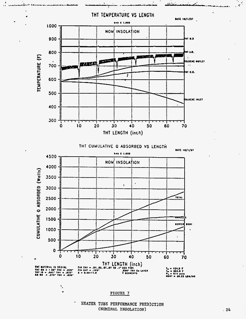
5.0 Performance Predictions
The heater tube was designed for supercritical toluene
flow. Therefore, ,any boiling phenomena is avoided., A .
thermal math model was developed to analyze the design
and determine how closely it meets the SD-ORC performance
requirements. The minimum power input ocours during the
nominal insolation orbit (solar constant 1.323 kW/m2) at
t h e end of t h e e c l i p s e 'period.
occurs during the maximum insolation orbit (solar
constant 1.419 kW/m2) at the end of the insolation
period. The design parameters and accompanying
pressure-enthalpy (P-H) diagram are summarized in Table
11.
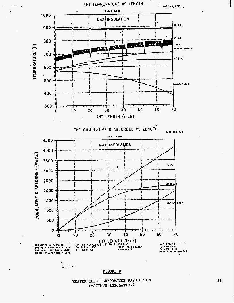
points are shown in Figures 7 and 8.
point is identified as a rr.min-insolationll and the maximum
design point is identified as vrmax-insolation.lr
model predicts that the design will adequately meet the
SD-ORC performance requirements.
temperatures are shown in Table 11.
drop across the THT is calculated to be 8 . 8 psi.
Maximum power input
The thermal model results based on the two design
The minimum design
The
The predicted outlet
The maximum pressure
c
8

Performance Test 1 Space Station Toluene Heater Tube
.n for a .
6.0 Planned Tests
Steady-State Thermal Performance Test
The series of tests are planned to determine the
steady-state performance characteristics of the toluene
heater tube. A minimum of two steady-state thermal and
hydraulic performance tests are planned which will permit
the various combinations of the inlet toluene mass flow,
pressure and temperature conditions to be investigated.
The test conditions are based upon the toluene heater
tube design parameters derived from the ORC solar dynamic
power system performance requirements for the Space
Station, and are shown on Table 111.
9
Performance Test Plan for a . Space Station To1 le Heater Tube
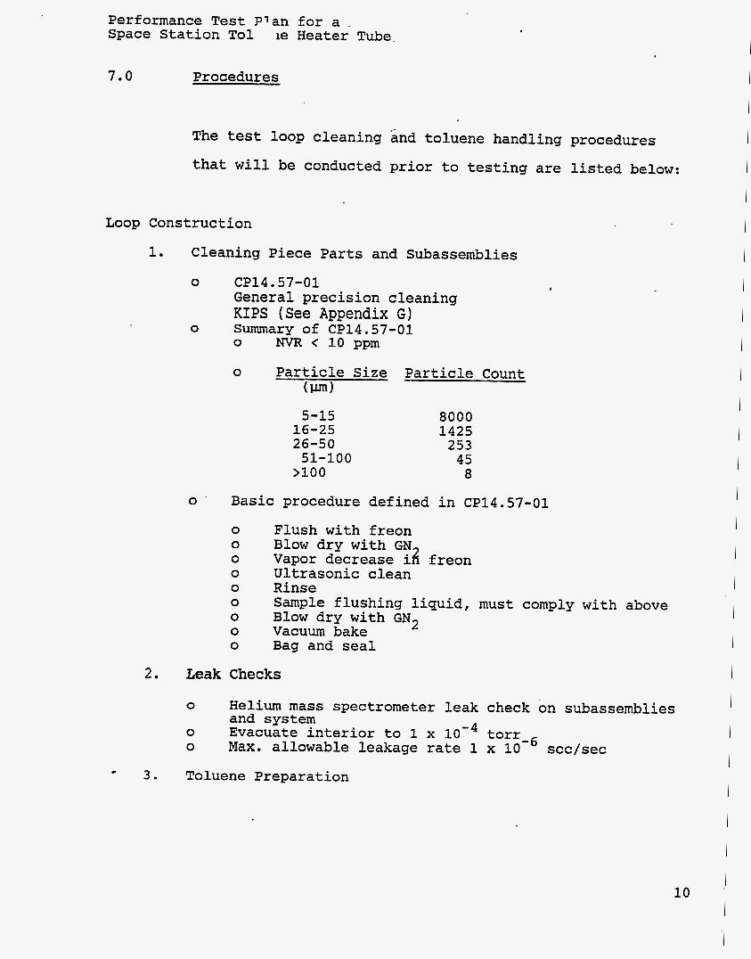
7.0 Procedures
The test loop cleaning and toluene handling procedures
that will be conducted prior to testing are listed below:
Loop Construction
1. Cleaning Piece Parts and Subassemblies
0
0
0
CP14.57-01 General precision cleaning KIPS (See Appendix G) Summary of CP14.57-01 0 NVR < 10 ppm
0 Particle Size Particle Count (Fun)
5-15 16-25 26-50
>loo 51-100
8000 1425 253 45 8
Basic procedure defined in CP14.57-01
0 0 0 0 0 0 0 0 0
Flush with freon Blow dry with GN Vapor decrease i8 freon Ultrasonic clean Rinse Sample flushing liquid, must comply with above Blow dry with GN2 Vacuum bake Bag and seal
2. Leak Checks
0
0 0
Helium mass spectrometer leak check on subassemblies and system Evacuate interior to 1 x lo'* torr-6 Max. allowable leakage rate 1 x 10 scc/sec
3 . Toluene Preparation
10

Performance Test Plan for a Space Station To1 le Heater Tube
0
0
Deaerate charge of toluene 0 Freeze under vacuum using liquid nitrogen 0 Repeat twice Load deaerated toluene into clean, evacuated system
4. Flushing
0 0 0 0
0
Charge evacuated circuit with deaerated toluene Heat fluidized bed Circulate toluene Analyze sample for:
1. Particulates per NAS1638, Class 5 2. Nonvolatile residue shall not exceed 10
ppm per 100 ml of fluid 3. Volatile contaminants shall. not exceed
amounts in original toluene sample Continue flushing until acceptable
c
11

Performance Test P1 an for a . Space Station To1 le Heater Tube.
8.0 Data Acquisition System
An existing Analog Devices MACSYM
acquisition system will be used to monitor and record the
temperature, pressure and mass flow data. The critical
parameters will also be recorded on the 8-channel brush
recorder.
automatic data
Table I describes the type of recording device
used for monitoring such parameters.
testing, including any anomalies, will be logged in the
THT test log book.
be recorded in the test data sheet shown in Table IV.
Test anomalies, if any identified, will be evaluated for
their impact on future testing.
corrective actions will be taken to minimize the impact
due to anomalies on further testing.
The daily record of
The inlet/outlet test parameters will
The appropriate
c
12 I

Performance Test Plan for a. Space Station To1 .le Heater Tube.
9.0 Report
A test report describing the test objectives, test
results and correlation with the analytical data, and
conclusions will be prepared and submitted as part of
meeting the contractual requirements.
13

Performance Test 3n for a : Space Station TolL .ae Heater Tube.
TABLE I
TOLUENE HEATER TUBE INSTRUMENTATION
& Parameters
1 Inlet Mass Flow
2 Inlet Temp (A)
3 Inlet Temp (B)
4 Inlet Pressure
5 Outlet Temp ( A )
6 Outlet Temp (B)
7 P (Pressure Drop)
8 Fluidized Bed Temp (A)
9 Fluidized Bed Temp (B)
10 Fluidized Bed Temp (C)
11 Thermal Standoff Temp (1)
12 Thermal Standoff Temp (2)
13 Thermal Standoff Temp ( 3 )
14 Thermal Standoff Temp ( 4 )
15 Thermal Standoff Temp (5)
16 Thermal Standoff Temp (6)
17 Thermal Standoff Temp (7)
18 Heater Tube Outer Skin Temp (1)
19 Heater Tube Outer Skin Temp (2)
20 Heater Tube Outer Skin Temp ( 3 )
Unit
Lb/hr
OF
OF
Psig
OF
OF
Ranse
0-72
RT-600
RT-600
0-1000
400-1000
400-1000
0-200
RT-12 0 0
RT- 1 2 0 0
RT-1200
RT- 1 2 0 0
RT- 1 2 0 0
RT- 120 0
RT-1200
RT-12 0 0
RT-1200
RT-12 0 0
RT-12 0 0
RT-12 0 0
RT-1200
Device *
Y
Y
Y
Y
Y
Y
Y
Y
Y
Y
Y
Y
Y
* NOTE: X - Brush Recorder Y - Digital Display
14
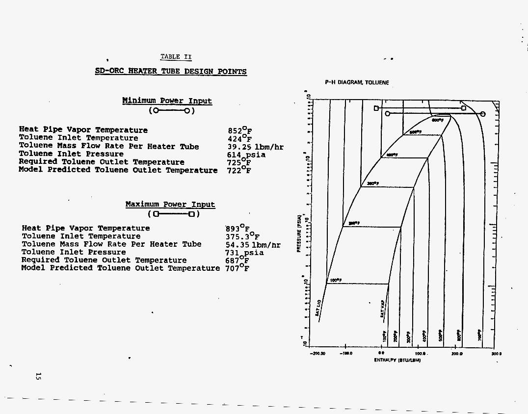
9 TABLE 11
SD-ORC HEATER TUBE DESIGN POINTS
Minimum Power Input (-1
H e a t Pipe V a p o r Temperature 852OF A C I A 0 ,
Toluene- I n l e t Temperature 4L4 r
Toluene Mass Flow Rate P e r Heater Tube 39.25 lbm/hr Toluene I n l e t Pressure 6 1 4 ops ia Required Toluene Outlet Temperature 72S0F Model Predicted Toluene Outlet Temperature 722 F
Maximum Power Input (-1
Heat Pipe V a p o r Temperature *8930F0 Toluene I n l e t Temperature 375.3 F Toluene Mass Flow Rate Per Heater Tube Toluene I n l e t Pressure Required Toluene Ou t l e t Temperature 687,F Model Predicted Toluene Ou t l e t Temperature 707 F
54.35 lbm/hr 7 3 lopsia
P-H DIAGRAM, TOLUENE
z! - - 8 3 -- In .- c -- a.
a-
m-
m
E- -- .- ..-
L
I
+ 100.0.

Performance Test "Ian for a Space Station To. 2ne Heater Tube
TABLE I11
TOLUENE HEATER TUBE TEST CONDITIONS
Bed Test Temp
NO (OF)
Toluene Flow lb/hr
Inlet Temp
(OF)
Inlet Pressure
(psis)
Solar Dynamic Power System Operating Condition
1
2
893
852
54.35
39.25
375
424
731
614
Maximum Input Power
Nominal Input Power
16

TABLE IV
TOLUENE HEATER TUBE TEST DATA
T e s t Run
D a t q
C Y c .. - -- INLET OUTLET PRESSURE FLUIDIZED THERMAL REMARKS
FLOW
TEST INLET INLET ?IO. TEMP. PRESS. MASS TEMP. DROP BATH STAND-OFF
TEMP TEMP OF PS i O F OF OF PS i l h /Hr
E n g i n e e r :
D a t e :

FIGURE 1 I
i ! ORC Heat Pipe Re,ceiver
Variations
Isothermal Source for T
0 Provides
0 Heat Added and Removed From
0 Well Characterized Constant Flux Same Surface
0 Free Expansion PCM Minimizes Fluid Degradation
Configuration
'ES
!
1:

FIGURE 2
TOLUENE HEATER TUBE TEST FACILITY
CONTROLS o FL.IiV)TZED RET) TEMP
1 I LW..
S 0 INTERMEDIATE OIL UIL U.L... b,..P. LOOP TEMP.
~ . - - __ -. -.
1
0 FLUID OVEATtM).. FLUTDIZED RED OVERTEMP
0 LOWINO WATEP nw 0 TOLUENE LEAk pi n\#CPTEMl
0 LOWINO TOLUENE FLOW 0 FIRE DETECTION 81
0 FEED PUMP FLOW 0 CONDENSER TEMP.
SUPPRESSION
REGENERATOR
WATER IN
WATER OUT
FLOWMETER
DAMPER
& FEED PUMP
!
VACUUM
LIQUID SAMPLE

a W m
c
I i !
Z
I- O Z
W
20
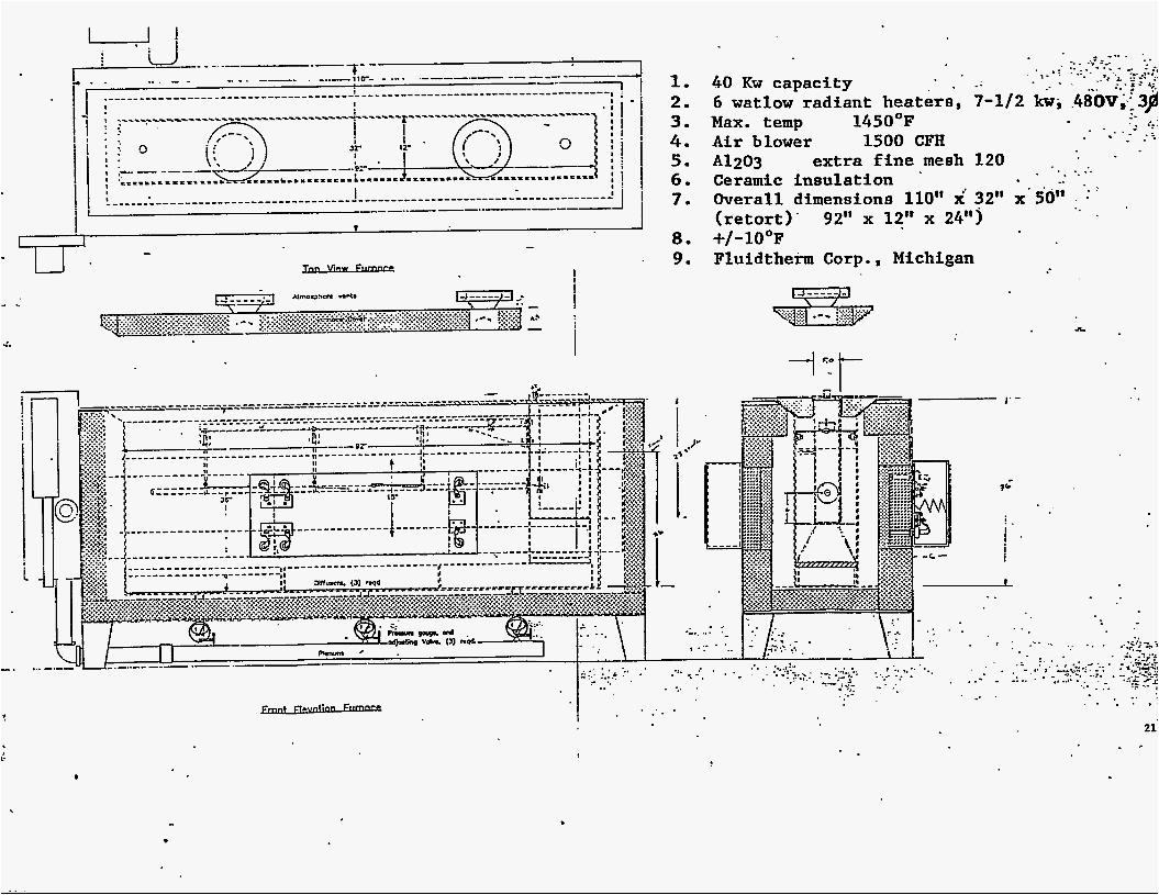
1. 2. 3. 4. 5 . 6 . 7 .
- U. ., ..
I .I.
8 . 9 .
40 Kw capacity 6 watlow radiant heaters, 7-112 kw, .480V,i3$ Max. temp 1450°F Air blower 1500 CFH
extra fine mesh 120 A1203 Ceramic insulation ' . . Overall dimensions 110" x* 32" x'50" (retort)' 92" x 12" x 2 4 9 +/-lO°F Fluidtherm Corp., Michigan
-- . - - . . 2:
. * . - - .;* . .
. . .. . . . .
, . .- .:.. . -. ... -
. .
. .. ' , .* , . . . . . 21
. -
c
Q
0 0 0 hl I-
'1 r
cn z 0 H H d 0 GI
e
hl
2
E
i2
3
F
.. 0
cn H
H H W W G l IJH 2 3 H O
22
I
I VIEW N-N
..
i
L
.-
a
T
n L,
W Q: 3 c
W a. =E w I-
Y
a
c
1000
900
800
700
600
500
400
300
THT TEMPERATURE VS LENGTH bob I I .DO0
wit 1 0 / 1 m
0 10 20 30 40 50 60 70 THT LENGTH (inch)
THT CUMULATIVE 0 ABSORBED VS LENGTH #Arc :./:/a7
bob I :.ODD
FIGURE 7
IRLLT
- HEATER TUBE PERFORMANCE PREDICTION (NOMINAL INSOLATION 1 . 24
1000
n &.
.W
3 c U
' C L : w a.
c
Y
'a
J
900
800
7 do
600 .. 500
400
300
4500
4000
3500
3000
2500
2000
1500
1000
500
0
- O A l t #@/$/a7 . THT TEMPERATURE VS LENGTH
THT LENGTH (inch)
HEATER TUBE PERFORMANCE PREDICTION (MAXIMUM INSOLATION)
25