Embed Size (px)
Citation preview
PERFORMANCE SUSPENSION PARTS
Air Lift Performance
IntroductionThe purpose of this publication is to assist with the installation, maintenance and troubleshooting of this Audi A6 C5 Performance kit.
It is important to read and understand the entire installation guide before beginning installation or performing any maintenance, service or repair . The information includes a hardware list, step-by-step installation information, maintenance tips, safety information and a troubleshooting guide .
NOTATION EXPLANATIONHazard notations appear in various locations in this publication . Information which is highlighted by one of these notations must be observed to help minimize risk of personal injury or possible improper installation which may render the vehicle unsafe . Notes are used to help emphasize areas of procedural importance and provide helpful suggestions . The following definitions explain the use of these notations as they appear throughout this guide.
INDICATES IMMEDIATE HAZARDS WHICH WILL RESULT IN SEVERE PERSONAL INJURY OR DEATH.
INDICATES HAZARDS OR UNSAFE PRACTICES WHICH COULD RESULT IN SEVERE PERSONAL INJURY OR DEATH.
INDICATES HAZARDS OR UNSAFE PRACTICES WHICH COULD RESULT IN DAMAGE TO THE MACHINE OR MINOR PERSONAL INJURY.
Indicates a procedure, practice or hint which is important to highlight.
IMPORTANT SAFETY NOTICESThe installation of this kit does not alter the Gross Vehicle Weight Rating (GVWR) or payload of the vehicle . Check your vehicle’s owner’s manual and do not exceed the maximum load listed for your vehicle .
Gross Vehicle Weight Rating: The maximum allowable weight of the fully loaded vehicle (including passengers and cargo) . This number — along with other weight limits, as well as tire, rim size and inflation pressure data — is shown on the vehicle’s Safety Compliance Certification Label.
Payload: The combined, maximum allowable weight of cargo and passengers that the vehicle is designed to carry. Payload is GVWR minus the Base Curb Weight.
DO NOT INFLATE AIR SPRINGS WHILE OFF OF THE VEHICLE. DAMAGE TO ASSEMBLY MAY RESULT AND VOID WARRANTY.
DO NOT WELD TO, OR MODIFY PERFORMANCE STRUTS/SHOCKS IN ANY WAY. DAMAGE TO UNIT MAY OCCUR AND WILL VOID WARRANTY.
DANGER
NOTE
WARNING
CAUTION
WARNING
CAUTION
Air Lift Performance
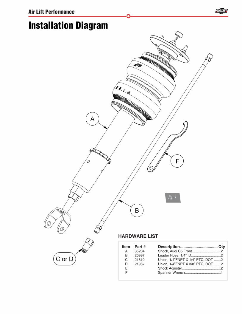
HARDWARE LIST
Item Part # Description . . . . . . . . . . . . . . . . . . . . . . . . . . . . . . . . . . Qty A 35204 Shock, Audi C5 Front . . . . . . . . . . . . . . . . . . . . . . . . . . . . .2 B 20997 Leader Hose, 1/4” ID . . . . . . . . . . . . . . . . . . . . . . . . . . . . . .2 C 21810 Union, 1/4”FNPT X 1/4” PTC, DOT . . . . . . .2 D 21987 Union, 1/4”FNPT X 3/8” PTC, DOT . . . . . . . .2 E Shock Adjuster . . . . . . . . . . . . . . . . . . . . . . . . . . . . . . . . . . . . . . .2 F Spanner Wrench . . . . . . . . . . . . . . . . . . . . . . . . . . . . . . . . . . . .1
Installation Diagram
fig. 1
B
A
C or D
F
Air Lift Performance
PREPARING THE VEHICLE1. Support vehicle with jack stands or a hoist at approved lifting points. 2 . Remove the front wheels
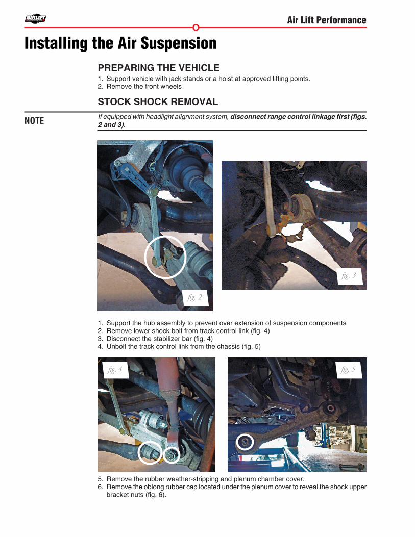
STOCK SHOCK REMOVALIf equipped with headlight alignment system, disconnect range control linkage first (figs. 2 and 3).
1 . Support the hub assembly to prevent over extension of suspension components2. Remove lower shock bolt from track control link (fig. 4)3. Disconnect the stabilizer bar (fig. 4)4. Unbolt the track control link from the chassis (fig. 5)
5 . Remove the rubber weather-stripping and plenum chamber cover . 6 . Remove the oblong rubber cap located under the plenum cover to reveal the shock upper
bracket nuts (fig. 6).
Installing the Air Suspension
NOTE
fig. 3
fig. 4 fig. 5
fig. 2
Air Lift Performance
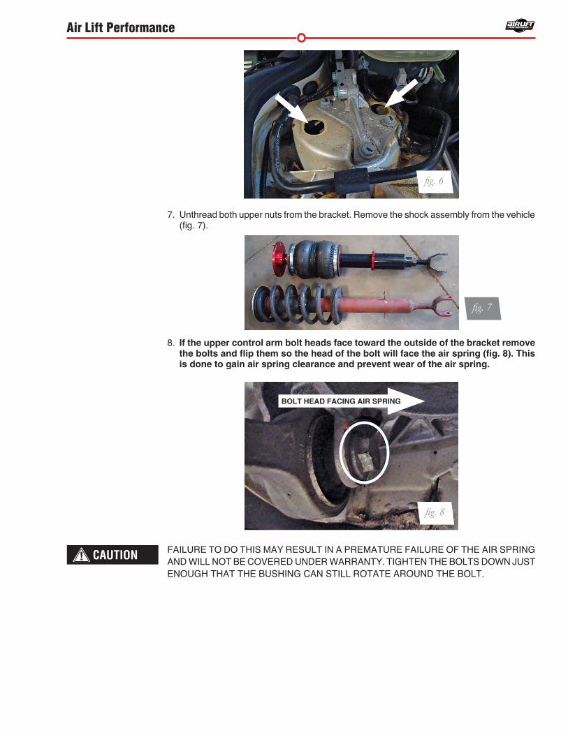
7. Unthread both upper nuts from the bracket. Remove the shock assembly from the vehicle (fig. 7).
8 . If the upper control arm bolt heads face toward the outside of the bracket remove the bolts and flip them so the head of the bolt will face the air spring (fig. 8). This is done to gain air spring clearance and prevent wear of the air spring .
FAILURE TO DO THIS MAY RESULT IN A PREMATURE FAILURE OF THE AIR SPRING AND WILL NOT BE COVERED UNDER WARRANTY. TIGHTEN THE BOLTS DOWN JUST ENOUGH THAT THE BUSHING CAN STILL ROTATE AROUND THE BOLT.
CAUTION
fig. 7
fig. 8
BOLT HEAD FACING AIR SPRING
fig. 6
Air Lift Performance
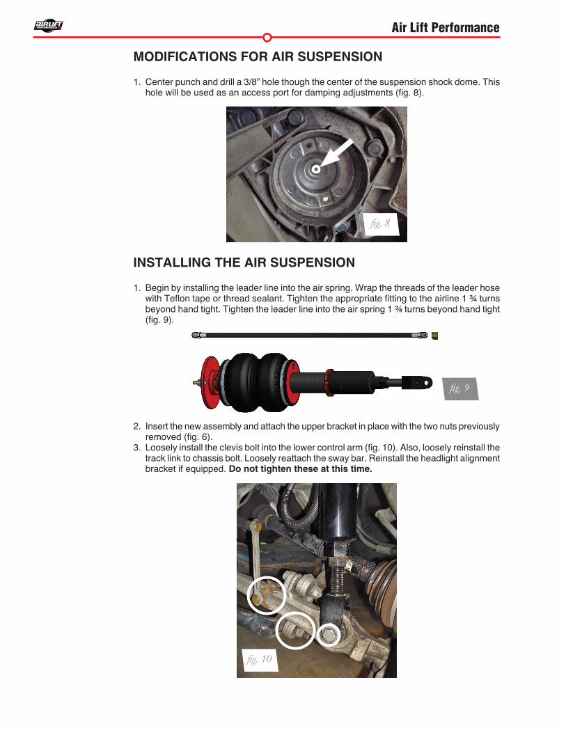
MODIFICATIONS FOR AIR SUSPENSION
1. Center punch and drill a 3/8” hole though the center of the suspension shock dome. This hole will be used as an access port for damping adjustments (fig. 8).
INSTALLING THE AIR SUSPENSION
1. Begin by installing the leader line into the air spring. Wrap the threads of the leader hose with Teflon tape or thread sealant. Tighten the appropriate fitting to the airline 1 ¾ turns beyond hand tight. Tighten the leader line into the air spring 1 ¾ turns beyond hand tight (fig. 9).
2 . Insert the new assembly and attach the upper bracket in place with the two nuts previously removed (fig. 6).
3. Loosely install the clevis bolt into the lower control arm (fig. 10). Also, loosely reinstall the track link to chassis bolt . Loosely reattach the sway bar . Reinstall the headlight alignment bracket if equipped . Do not tighten these at this time .
fig. 8
fig. 10
fig. 9
Air Lift Performance
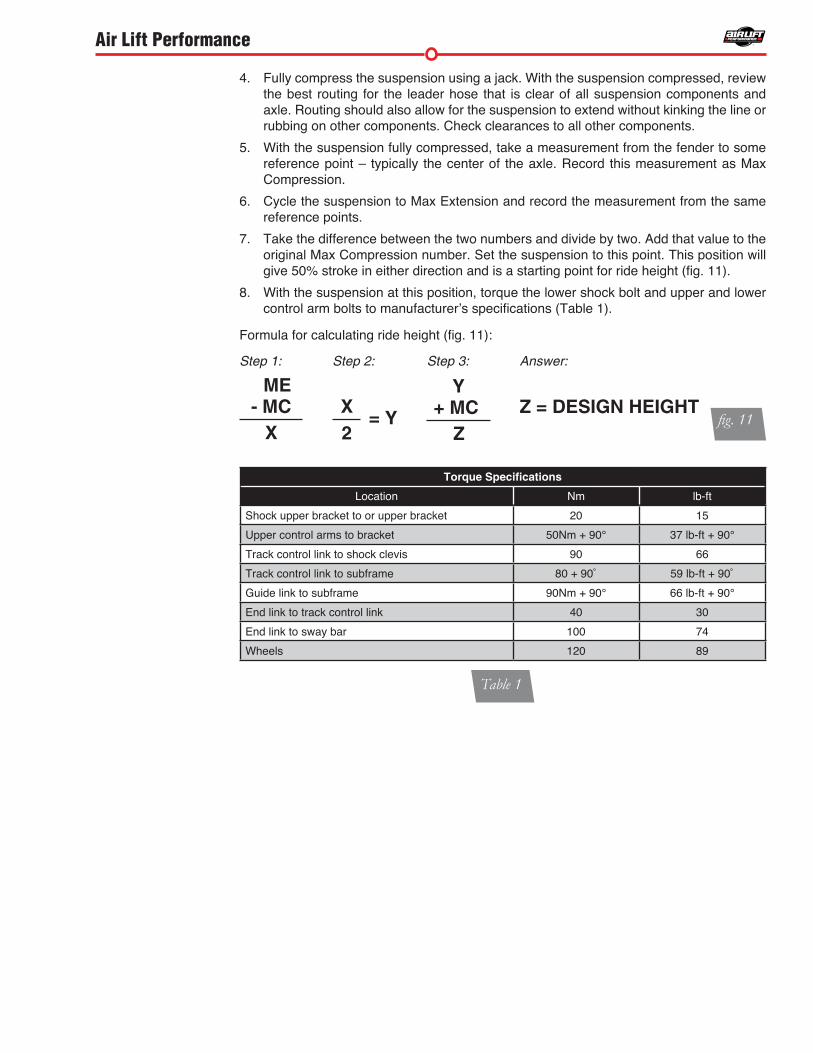
Torque Specifications
Location Nm lb-ft
Shock upper bracket to or upper bracket 20 15
Upper control arms to bracket 50Nm + 90° 37 lb-ft + 90°
Track control link to shock clevis 90 66
Track control link to subframe 80 + 90˚ 59 lb-ft + 90˚
Guide link to subframe 90Nm + 90° 66 lb-ft + 90°
End link to track control link 40 30
End link to sway bar 100 74
Wheels 120 89
4. Fully compress the suspension using a jack. With the suspension compressed, review the best routing for the leader hose that is clear of all suspension components and axle . Routing should also allow for the suspension to extend without kinking the line or rubbing on other components . Check clearances to all other components .
5. With the suspension fully compressed, take a measurement from the fender to some reference point – typically the center of the axle . Record this measurement as Max Compression .
6 . Cycle the suspension to Max Extension and record the measurement from the same reference points .
7. Take the difference between the two numbers and divide by two. Add that value to the original Max Compression number . Set the suspension to this point . This position will give 50% stroke in either direction and is a starting point for ride height (fig. 11).
8. With the suspension at this position, torque the lower shock bolt and upper and lower control arm bolts to manufacturer’s specifications (Table 1).
Formula for calculating ride height (fig. 11):
fig. 11
ME- MC
X
Step 1:
+ MC
Z
YStep 3:
Z = DESIGN HEIGHT
Answer:
X = Y 2
Step 2:
Table 1
Air Lift Performance
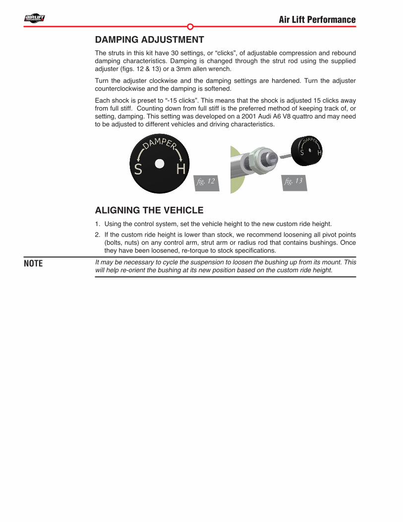
DAMPING ADJUSTMENT The struts in this kit have 30 settings, or “clicks”, of adjustable compression and rebound damping characteristics . Damping is changed through the strut rod using the supplied adjuster (figs. 12 & 13) or a 3mm allen wrench.
Turn the adjuster clockwise and the damping settings are hardened. Turn the adjuster counterclockwise and the damping is softened .
Each shock is preset to “-15 clicks”. This means that the shock is adjusted 15 clicks away from full stiff . Counting down from full stiff is the preferred method of keeping track of, or setting, damping. This setting was developed on a 2001 Audi A6 V8 quattro and may need to be adjusted to different vehicles and driving characteristics.
ALIGNING THE VEHICLE1. Using the control system, set the vehicle height to the new custom ride height.
2 . If the custom ride height is lower than stock, we recommend loosening all pivot points (bolts, nuts) on any control arm, strut arm or radius rod that contains bushings. Once they have been loosened, re-torque to stock specifications.
It may be necessary to cycle the suspension to loosen the bushing up from its mount. This will help re-orient the bushing at its new position based on the custom ride height.
fig. 12 fig. 13
NOTE

Air Lift Performance
ADJUSTING EXTENDED OR DROP HEIGHT USING LOWER MOUNTYour struts have been pre-set at the factory to provide maximum drop height while maintaining adequate tire clearance to the air spring . If you wish to gain more extended height (lift), which is the same as reducing drop height, or want to lower the chassis further and there is still adjustment available at the lower mount, please use the following procedure:
1. Support the vehicle with jack stands or a hoist at approved lifting points.
2 . Remove the wheel .
3. Using the supplied spanner wrench, loosen the lower locking collar (fig. 14).
4. Deflate the air spring to 0 PSI on the corner you are adjusting.
5 . Disconnect lower mount from suspension .
6 . Spin the lower mount to the desired location .
Not all models will have further drop height available.
7. Re-install lower mount to suspension and torque fasteners.
8. Tighten the lower locking collar to the lower mount using significant force.
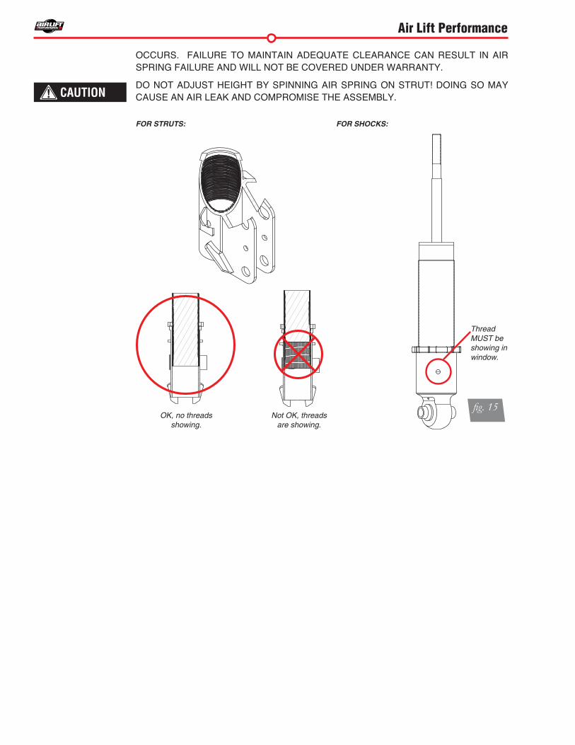
WHEN ADJUSTING HEIGHT UPWARDS, MAKE SURE THAT THE STRUT BODY ENGAGES ALL THE THREADS OF THE LOWER MOUNT (FIG. 15). WHEN ADJUSTING DOWNWARDS, MAKE SURE THERE IS ADEQUATE AIR SPRING CLEARANCE TO THE TIRE/WHEEL ASSEMBLY. CLEARANCE MUST BE CHECKED WITH SYSTEM FULLY DEFLATED AS WELL AS FULLY INFLATED TO ENSURE THAT NO RUBBING
fig. 14
NOTE
CAUTION
Air Lift Performance
CAUTION
FOR STRUTS: FOR SHOCKS:
Thread MUST be showing in window.
OK, no threads showing.
Not OK, threadsare showing.
fig. 15
OCCURS. FAILURE TO MAINTAIN ADEQUATE CLEARANCE CAN RESULT IN AIR SPRING FAILURE AND WILL NOT BE COVERED UNDER WARRANTY.
DO NOT ADJUST HEIGHT BY SPINNING AIR SPRING ON STRUT! DOING SO MAY CAUSE AN AIR LEAK AND COMPROMISE THE ASSEMBLY.