Embed Size (px)
Citation preview

[1]
PERFORMANCE STUDY & EVALUATION OF ELECTRICAL PARAMETER OF DRAGLINE IN OPEN CAST MINES
THIS THESIS SUBMITTED IN PARTIAL FULFILLMENT OF THE REQUIREMENTS FOR THE DEGREE OF
MASTER OF TECHNOLOGY
IN
MINING ENGINEERING
BY
ATMA RAM SAHU
213MN1498
Under the guidance of
PROF. H.K.NAIK
DEPARTMENT OF MINING ENGINEERING
NATIONAL INSTITUTE OF TECHNOLGY
ROURKELA-769008
2014 -15

[ii]
Dedicated to my teacher’s & family

[iii]
DEPARTMENT OF MINING ENGINEERING
NATIONAL INSTITUTE OF TECHNOLGY
ROURKELA-769008
`
CERTIFICATE
This is to certify that the thesis entitled “Performance Study & Evaluation of
Electrical Parameter of Dragline in Open Cast mines” submitted by Mr. Atma Ram
Sahu in partial fulfillment of the requirements for the award of Master of Technology
degree in Mining Engineering at National Institute of Technology, Rourkela is an authentic
work carried out by him under my supervision and guidance.
To the best of my knowledge, the matter embodied in the thesis has not been submitted
to any other University/Institute for the award of any Degree
Date; Prof. H.K.NAIK
Head of department of Mining Engineering, National Institute of Technology Rourkela – 769008

[iv]
ACKNOWLEDGEMENT
First and foremost, I express my profound gratitude and indebtedness to Prof.
H.K.Naik, Department of Mining Engineering for allowing me to carry on the present topic
“Performance Study & Evaluation of Electrical Parameter of Dragline in Open Cast
mines” and his able guidance and pain taking effort in improving my understanding in this
project.
I am very much thankful to NCL (Northern Coalfields Limited), Singrauli (MP) mines
authorities for providing all help, guidance and facilities in terms of data collection and
mine visit during the period of this project work. Assemblage of this nature could never
have been attempted without the reference to and inspiration from the works of others
whose details are mentioned in the reference section. I acknowledge my indebtedness to all
of them.
At last, my sincere thanks to all my friends who have patiently extended all sorts of
helps for accomplishing this assignment.
Date : Atma Ram Sahu

[v]
ABSTRACT
Draglines are the most expensive piece of excavating equipment at the mine site and it’s operated safely, efficiently and economically. In order to achieve high production and productivity of heavy earth moving machine in opencast mines, it is necessary to have high % availability and % utilization of equipment. The study also propounds the importance of appraisal of dragline productivity parameters, such as, swing angle, availability, seating position, cycle time, utilization, etc., in the field scale. In this contest, calculation of operating cost of dragline operation in various methods has been done and compared critically on case study basis. Principally, it will serve as a guide to the method employed in determining the operating cost in various methods. Draglines are versatile and provide a low cost mining method.
Each dragline that is considered for an AC Electrical upgrade will be fully analyzed to determine the machines maximum potential productivity increases. The assessment will include review of current dragline productivity practices, installed electrical capability and additional mechanical enhancements that could be included, such as increased suspended load, which will allow us to take full advantage of the AC IGBT/AFE system and BI 348 motor with its increased capability and still operate the machine within Bucyrus recommended criteria. The AC IGBT/AFE System has a fully integrated onboard computer package that allows complete access to the drive application software and PLC software and chopper drive use in regenerative braking. It is called access direct which will be discussed.
Surface mining ventures like Amlori open cast project of NCL, Singrauli (M.P.) with coal production targets (about 20 million tons per annum) this is possible to remove large volume of overburden in shortest possible time. Northern Coalfields Limited (NCL) is the only subsidiary company of CIL, where the entire coal production (98 %) is mined by opencast mining method and 40 % of the large volume of overburden excavation is done with the help of larger walking draglines. Draglines are used in all the mines of NCL except in Gorbi, Jhingurda, and Kakri. NCL was formed by November 1985 as a subsidiary company of CIL. The mine's output is totally dependent on the dragline’s parameters and different drive technology, PLC technology to increase the production of mines. In this thesis an attempt is made to discuss the different parameter and how to increase the efficiency, Utilization, Availability, production rate of dragline.
[vi]
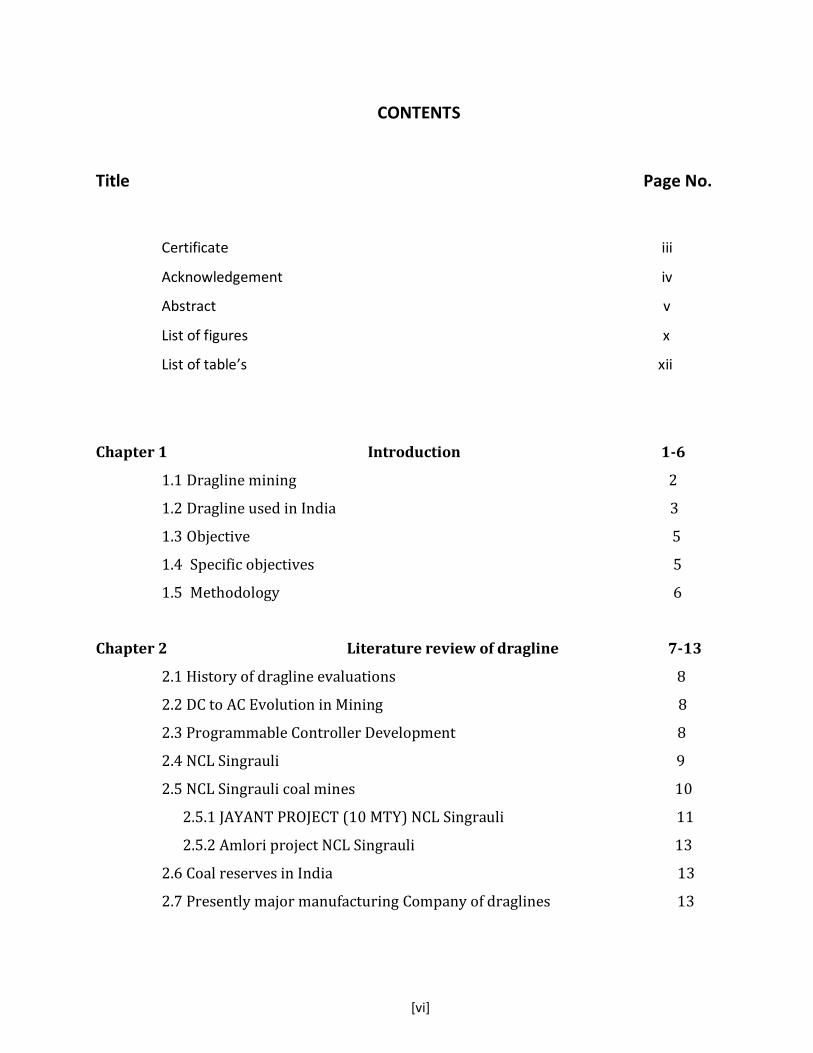
CONTENTS
Title Page No.
Certificate iii
Acknowledgement iv
Abstract v
List of figures x
List of table’s xii
Chapter 1 Introduction 1-6
1.1 Dragline mining 2
1.2 Dragline used in India 3
1.3 Objective 5
1.4 Specific objectives 5
1.5 Methodology 6
Chapter 2 Literature review of dragline 7-13
2.1 History of dragline evaluations 8
2.2 DC to AC Evolution in Mining 8
2.3 Programmable Controller Development 8
2.4 NCL Singrauli 9
2.5 NCL Singrauli coal mines 10
2.5.1 JAYANT PROJECT (10 MTY) NCL Singrauli 11
2.5.2 Amlori project NCL Singrauli 13
2.6 Coal reserves in India 13
2.7 Presently major manufacturing Company of draglines 13

[vii]
Chapter 3 Operation of Dragline 14-26
3.1 Classification of draglines 15
3.2 Selection of Mining Equipment depend on the following parameter 15
3.3 Conditions suitable for dragline mining 16
3.4 Advantages of dragline mining 16
3.5 Disadvantages of dragline mining 17
3.6 Annual productive capacity 19
3.7 Factors Affecting the Dragline Productivity 19
3.8 Idle hours 19
3.9 Cycle time 20
3.10 Factors Affecting Cycle Time 20
3.11 To Reduce Cycle Time of Dragline 21
3.12 Maximizing payload is dependent upon the factor 21
3.13 Dig rate 22
3.14 Digging pattern 22
3.15 Method of Digging 22
3.16 Chop down cut 22
3.17 Condition Monitoring 23
3.18 Analysis Methods 24
3.19 Dragline operation in tandem-vertical and tandem horizontal mode 25
3.20 Method of Excavation 27
Chapter 04 Drive Technology of a Dragline in Open Cast Mines 28-39
4.1 Variable Speed drives in dragline 29
4.2 Advantage of variable drive system 29
4.3 Methods of speed control 29
4.4 Ruggedized DC-EXX Modules 29
4.5 DC Converter 30
[viii]
4.6 Regenerative Braking of dc motor 31
4.7 Four Quadrant Operation Chopper Drive 32
4.8 AC Technology 33
4.9 AC Main Motion Drive Motors 34
4.10 Barriers to AC 35
4.11 AC Gearless Dragline 35
4.12 AC Conventional Dragline 35
4.13 Advantage of AC convention drive 36
4.14 Availability / Reliability (compared to DC Ward-Leonard) 38
4.15 Drive Power Transformer (DPT) 38
4.16 AC IGBT/AFE Conventional 39
4.17 Active Front End (features) 39
4.18 IGBT (Insulated Gate Bipolar Transistor) 40
Chapter 05 Programmable Logic Controller (PLC) 42-50
5.1 PLC (Programmable Logic Controller) 43
5.2 PLC system of Dragline Lube Control 44
5.4 PLC Scan 44
5.4 Memory used in PLC system having 3 types 45
5.5 Basic Components of PLC 45
5.6 Basic Operation of PLC system in dragline 46
5.7 PLC Input and Output Devices of dragline 46
5.8 PLC Special Features 46
5.9 Time Delay Relays 47
5.10 Counters 47
5.11 Functions of controller 47
5.12 Alarm System 47
5.13 Integrated Support Centers (ISCs) 49

[ix]
Chapter 06 Trailing cables of dragline 51-53
6.1 Construction Trailing Cable 52
6.2 Potential Hazards 53
6.3 Recommendations 53
Chapter 07 Computer aided design, modeling and analysis 54-60
of bull gear of a drag line
7.1 Modeling Procedure of Bull Gear 55
7.2 Finite element approach 56
7.3 Rigging mechanism 56
7.4 Finite Element Analysis (FEA) of dragline bucket 58
7.5 Cutting Resistance Models (Analytical Approaches) 59
Chapter 08 Result & discussion 61-72
8.1 Dragline balancing diagram of dragline 62
8.2 Preparation of Dragline balancing diagram 62
8.3 Calculation of annual output, operating cost, ownership, and cost/ 63
tone of coal exposed in dragline in Amlori project NCL Singrauli
open cast mine
8.4 Evaluation of Availability (A) and Utilization (U) 64
8.5 Digging hours 65
8.6 Computation of Efficiency of Draglines 66
8.7 Calculation of Coal Exposure of dragline 66
8.8 Estimation of Operating Cost 67
8.9 Formula of maximum depth that can be worked by a dragline 72
is given

[x]
Chapter 09 Conclusion 74-75
List of figure
Figure No. Caption Page
Figure: 1.1 Schematic diagram of a dragline 2
Figure; 2.1 Coal flow of NCL Singrauli in 2011-12 11
Figure: 2.2 Over burden removal Jayant project 12
Figure; 2.3 Jayant project coal production 12
Figure; 2.4 Coal reserves in India 13
Figure; 3.1 Line diagram of dragline 15
Figure; 3.2 Dragline model Abhimanyu at NCL Amlohri 17
Finger: 3.3 Year wise % of total volume handling by dragline in NCL 19
during “96-06”
Figure: 3.4 Different postion of digging face 23
Figure; 3.5 Demographics analysis 25
Figure: 4.2 Drive motor field current 30
Figure; 4.3 Dragline M-G set 31
Figure; 4.4 Different mode of control of dragline drive system 31
Figure; 4.5 Four quadrant operation of motor 32
Figure; 4.6 Experimental setup drives 34
Figure; 4.7 Diagnosis system of dragline, IGBTs-switching, voltage sensor 34
and delay times compensation on the fault detection signal
in different condition
Figure; 4.8 Drive control system of AC Conventional drive 36
Figure: 4.9 Principle connection of AC drive system 37
Figure: 4.10 Smooth operation with new AC drives 38
Figure; 4.11 Positive half cycle of operation 40
[xi]
Figure; 4.12 Negative half cycle mode of operation 40
Figure; 4.13 AC IGBT/AFE Convention drive 41
Figure: 5.1 PLC based Dragline Control 43
Figure: 5.2 PLC Scan 44
Figure: 5.3 General view of PLC system 45
Figure: 5.4 Operation of a PLC System 46
Figure: 5.5 Alarm system of dragline with diagnostic system 48
Figure: 5.6 Diagnostic screen of dragline 48
Figure; 5.7 PLC Software (RSLogix 500) – Commercial 49
Figure; 6.1 Trailing Cable having Construction voltage rating 6.6 kv, 53
diameter 100mm
Figure; 7.1 Modelling of Bull Gear 55
Figure: 7.2 Drafting of Bull Gear 55
Figure; 7.3 Computer Aided Modeling of Bull Gear 56
Figure: 7.4 Elements of Dragline Bucket and Rigging Mechanism 57
Figure: 7.5 Penetration and Separation Parts of a Bucket 60
Figure: 7.6 Failure Plane in Formation Cutting 58
Figure 8.1: Balancing diagram of Dragline 62

[xii]
List of Table
Table No. Caption Page No.
Table: 1.1 Dragline operation of India 4
Table: 1.2 Present Dragline of India coal mines 5
Table 2.1 Present Draglines of NCL Singrauli 10
Table 2.2 Dragline used in NCL having basin 10
Table 3.1 Idle hour analysis 20
Table 3.2 Machine parameters and Key field parameters that are used to 26
make balancing diagram of vertical tandem mode of operation
Table 3.3 Operation Horizontal tandem mode, Weighted and overall cycle 26
time for 24/96 lagging dragline Abhimanyu (LaHT-D/L) and
rehandled muck (loose over burden) for mine
Table 3.4 Machine parameters and Key field parameters that are used to 27
make balancing diagram of horizontal tandem mode of
Table 7.1 Part of dragline bucket 51
Table: 8.1 Productivity factors for dragline as per CMPDI recommendations 66
Table 9.1 Estimated cost of dragline in different mode of operation 74

Chapter 1
INTRODUCTION

NIT ROURKELA 2
1. Introduction
1.1 Dragline mining
A dragline excavator is a piece of heavy equipment used in removal of overburden in surface
mining. Draglines used in civil engineering for the construction of port, road, pond, and canal
dredging. Mining is one of the most important activities to extract resource from the earth’s crust.
Mining is divided into two main parts.
Underground mining
Surface mining.
In open cast mines draglines are used to excavate a maximum of 50 to 80m of overburden to
reach dump height of about 39m (Ref: collected data from NCL, Singrauli, Amlori project).
Demand of energy is continuously increasing in India, coal which is full fill the requirement of fuel
which spread raw material (fossil fuels) throughout the earth's crust. A most considerable part of
coal is produced by open cast mining methods.
Fig: 1 Schematic diagram of a Dragline
Walking dragline is a principal tool in open cast mining operations which removes large
amounts of overburden material in order to expose valuable minerals to be mine in depth of
earth crust. In order to increase the efficiency of such machines used in new technology of drive
system with PLC controller and larger in size of bucket, boom length and in their load-carrying
capabilities. In order to improve dynamic response time and decrease digging cycle time, digging
time and overall performance have to be approve by increased the workload on the operator and
has probably made the operator more susceptible to error.

NIT ROURKELA 3
1.2. Dragline used in India
Coal producers have already tried to open up big surface coalmines in various coalfields by used
in dragline to remove over burden. Indian mining industry has contributed significantly amount
of coal to make the nation self-sufficient in coal for systems to remove large volume of
overburden in shortest possible time by used large walking dragline.
Draglines used in India for overburden stripping because of their fast controlling, required
less manpower, production of coal per unit cost is less as compared to other method of removal
of over burden, high production rate and flexibility. Hence, the Indian open cast coal mining has
been used dragline mining for removal of overburden in most of large sized coal mines to
increase the high rate production.
Dragline operation of India
Table: 1.1 Dragline operation of India

NIT ROURKELA 4
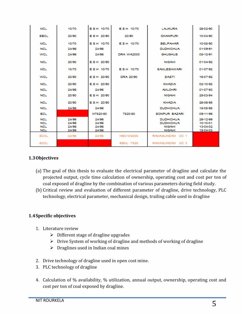
Present Dragline of India coal mines
Table: 1.2 Present Dragline of India coal mines
NIT ROURKELA 5
1.3 Objectives
(a) The goal of this thesis to evaluate the electrical parameter of dragline and calculate the
projected output, cycle time calculation of ownership, operating cost and cost per ton of
coal exposed of dragline by the combination of various parameters during field study.
(b) Critical review and evaluation of different parameter of dragline, drive technology, PLC
technology, electrical parameter, mechanical design, trailing cable used in dragline
1.4 Specific objectives
1. Literature review
Different stage of dragline upgrades
Drive System of working of dragline and methods of working of dragline
Draglines used in Indian coal mines
2. Drive technology of dragline used in open cost mine.
3. PLC technology of dragline
4. Calculation of % availability, % utilization, annual output, ownership, operating cost and
cost per ton of coal exposed by dragline.
NIT ROURKELA 6
5. Trailing Cable.
6. Study of stress distribution in a dragline bucket using finite element analysis (FEA)
1.5 Methodology
The specific objectives were achieved by following methods:
1. Study of available literature and different stage of upgrades of different parameter
of dragline
2. Visit to mines NCL Sinngrauli project Amlori abhimantu dragline for collecting data.
3. Calculation of different parameter of dragline.
4. Stress distribution of dragline bucket is investigated using FEA

NIT ROURKELA 7
Chapter 02
LITERATURE REVIEW OF DRAGLINE

NIT ROURKELA 8
2.1. History of dragline evolutions
1904: W. Page of Page Schnabel used in Chicago canal.
1910: Bucyrus International Company introducing first crawler mounted dragline.
1912: Page Engineering Company providing draglines with mobility.
1939: Marion Steam Shovel Dredge Company builds its first walking mechanism.
2.2 DC to AC Evolution in Mining
(20th Century)
1920’s Ward-Leonard Generator DC drives introduced on Shovels & Draglines.
1970’s General Industry starts migration to AC drives.
1976 Bucyrus forms alliance with Siemens for AC drive development.
1980 Bucyrus introduces analog SCR AC drives - shovels and small draglines.
1989-1998 Bucyrus introduces digital GTO AC drives - shove small draglines and large
dragline swing.
1999 Bucyrus & Siemens design next generation of AC Drives utilizing AC IGBT/AFE
technology - shovels and large dragline swing
1999-2006 Bucyrus sells AC IGBT/AFE drives for 495BII, HD, HR & HF shovels and large
dragline swing - 2570WS.
2003 Bucyrus & Siemens develop first all AC IGBT/AFE gearless drive system using
Synchronous Motors for Hoist and Drag - large draglines.
2004 Bucyrus sells first AC IGBT/AFE gearless 8750 dragline (start up due late 2006).
2006 Bucyrus & Siemens develop new AC drive motor (same motor for all motions - BI
348) in conjunction with existing AC IGBT/AFE technology for use with conventional
gearing - small and large draglines.
2006 Bucyrus sells first AC IGBT/AFE Conventional 8750 Dragline to Lake Lindsay in
Australia
2.3 Programmable Controller Development
1968 Programmable concept develop
1969 Hardware CPU controller, with logic instructions, 1 K of memory and 128 I/O
points.
1974 Use of several (multi) processors within a PLC - timers and counters; arithmetic
Operations; 12 K of memory and 1024 I/O points.
1976 Remote input/output systems introduced
1977 Microprocessors - based PLC introduced
1983 Low - cost small PLC’s introduced
1985 Networking of all levels of PLC, computer and machine using SCADA software.

NIT ROURKELA 9
2.4 NCL Singrauli
NCL is the only subsidiary company of Coal India limited, where the all most coal production (98
%) is mined by surface mining method. NCL used in dragline to remove about 40% of the large
volume of over burden is removed. NCL was formed by November 1985 as a subsidiary company
of CIL. Head quarter of Northern Coalfields Limited located in Singrauli. The area of coal field is
about 2202 km square and this region is called Capital Power of India. The coal field divided
into two basins.
1. Singrauli main basin (1890 km square)
2. Mohar sub-basin (132 km square)
The most part of the Moher sub-basin lies in the Singrauli district of (M.P.) and a small part of
the Moher sub-basin lies in the Sonebhadra district of (U.P.). The coal supplies from NCL have
made it possible to produce more than 11000 MW of electricity from power plants of NTPC and
Uttar Pradesh Rajya Vidyut Utpadan Nigam Ltd (UPRVUNL) and Renupower division of M/s.
Hindalco Industries. The region is called the Capital power of India. The total capacity of power
generation of these power plants is 13295 MW and NCL is fully prepared to meet the increased
demand of coal for the purpose. In addition, Northen coal field limited supplies coal to power
plants of Rajasthan Rajya Vidyut Utpadan Nigam, Haryana Power Generation Corporation Limited
and Delhi Vidyut Board (DVB).
Present status of Draglines in NCL
Table 2.1 Present Draglines of NCL Singrauli

NIT ROURKELA 10
Dragline used in NCL having basin.
Table 2.2 Dragline used in NCL having basin
2.5 NCL Singrauli coal mines
Amlori project
Jayant project
Bina
Dudhichua

NIT ROURKELA 11
Jhangurdah
Kakri
Khadia
Nigahi
Krishnashila
CWS project
IWSS project
Gorbi block-B
NSC
Fig; 2.1 Coal flow of NCL Singrauli in 2011-12
2.5.1 JAYANT PROJECT (10 MTY) NCL Singrauli
The project is located in south-central part of the Moher Sub-basin of Singrauli Colafield. The
area geographically lies between latitudes of 24 0 9 ' 50 “ to 24 0 11 ' 25” North and longitudes 82
0 38' 25 “ to 82 0 41' 42 “ East and comprise Gondwana rocks covering about 312 sq km of which
coal bearing Barakars occupy 225 sq km. The project has achieved highest ever composite
production of 31.68 M. Cum in the year 2010-11, which is not only highest in NCL but also in Coal
India Limited.
MINING AND GEOLOGICAL CONDITION

NIT ROURKELA 12
OB thickness: - : 10m (at outcrop) 180m (N-E part)
Av. Stripping ratio : 2:60
Over Burden : 90% is medium and coarse grained sand stone
Capital cost as per RCE : Rs 375.05 Cr. (Sanction date Nov. 1989)
Capital Investment (till : Rs 1038.41 Crs (Including Rs 494.85 Crs 31.03.2012)
replacement capital)
Mining block area : 1110 Ha.
Lease hold area : 2717 Ha.
peak production capacity of 25 Mtpa
Over burden removal jayant project
Fig: 2.2 Over burden removal jayant project
Jayant 20 MTPA expansion programme
Fig; 2.3 Jayant project coal production

NIT ROURKELA 13
2.5.2 Amlori project NCL Singrauli
The feasibility study prepared by CMPDI with participation of Russian experts in 1974 has
identified Amlori open cast mine with rated capacity of 10 MT/year. The Amlori black stand as
high plateau over the Talchair plains in the south. The plateau raises a maximum height of 520m
above the MSL. Feasible report sanctioned on – 25/06/1982
Capital investment – Rs. 323.32 crore
Revised coal estimated sanctioned – Rs. 527.11 crore
Coal production start – 1987-88
Seam gradient – 2 - 5
Stripping ratio – 4.41
Depth of quarry – 300m
Mineral reserve – 325.04MT
Volume of overburden – 1434.38 M cum
2.6 COAL RESERVES IN INDIA
GSI estimated a total of 257.38 billion tonnes of coal reserves on 1.1.2007 of which are the "Prime"
coking coal are 5.313 billion tonnes, semi-coking and medium coals are 27.04 billion tonnes and non-
coking coals are 225.03 billion tonnes.
Fig: 2.4 COAL RESERVES IN INDIA
2.7 Presently major manufacturers Company of draglines.
Bucyrus Erie (US)
Page (US)
Marion (US)
Rapier and Ransom (UK)
Soviets.

NIT ROURKELA 14
Chapter 3
Operation of Dragline

NIT ROURKELA 15
3.1 Classification of draglines
3.2 Selection of Mining Equipment depend on the following parameter
• Stripping Ratio
• Life of the mine
• Demand of coal
• Available of electrical power
• Available of manpower
• Amount of capital investment
• Type of land
• Geological parameter
• Infrastructure available
• Proposed annual output
• Technology available
Fig. 3.1: Line diagram of dragline

NIT ROURKELA 16
3.3 Conditions suitable for dragline mining
1. Gradients flatter than 10˚ (1 in 6)
2. Seams should be free of faults, fracture & other geological disturbances.
3. Deposits with Major Strike length are available.
4. Thick seams with more than 25m thick are not suitable.
5. A hilly property is not suitable.
6. Property should have at least 15 years life.
7. The ‘ King pin’ of the mine.
8. 40% of the OB is handled by the Draglines.
9. High Cost, for 24/96 Dragline is Rs. 160 Crore
10. Loss per hour Rs. 2,00,000/- approx., if not worked
3.4 Advantages of dragline mining
• Direct Disposal
• Can also be used to dig above working level at reduced production rate
• Less frequent movement
• Not significantly affected by the adverse weather
• Safe from unstable slopes, pit flooding etc
• Flexible, can be applied in different operating techniques

NIT ROURKELA 17
• Lowest cost per unit moves
3.5 Disadvantages of dragline mining
Requires bench preparation; Max slope: 2% Max ramp : 10 %
Does not dig poor blast well
High investment Cost
Rehandling reduces the productivity
Additional leveling Cost of spoil peaks
Fig: 3.2 Dragline Abhimanyu at NCL Amlohri
WALKING DRAGLINE
MODEL : WD 24/96
MAKE : HEC – RANSOM & RAPIER
WORKING DATA
BUCKET CAPACITY 24 CUB. METRE
BOOM LENGTH 95.6 METRE
BOOM ANGLE 30ₒ
OPERATING RADIUS 88 METRE
MAX. DUMP HEIGHT 39 METRE
MAX. DIGGING DEPTH 53 METRE
AVERAGE GROUND PRESSURE 1.03KG/SQ.CM
CLEARANCE RADIUS 22 METRE
WIDTH OVER BOTH SHOES 23 METRE
NIT ROURKELA 18
BOOM HEADS HEIGHT 54 METRE
WEIGHT OF THE MACHINE 2000 TONNE
WALKING SPEED 240 MPH (35 SECONDS A STEP)
LEGNTH OF A STEP 2.3METRE
PRODUCTION CAPACITY 3.6 MILLION CUB. METRE PER ANNUM
DATE OF COMMISSIONING 1.10.1983
PROGRESSIVE WORKING HRS 1,77,632 HOURS
PROG. MATERIAL HANDLED 111 MILLION CUB. METRE
AVG. WORKING HOUR/DAY 18.5 HOURS
BUCKET
WEIGHT 32 TONNE
MAX. SUSPENDED LOAD 77 TONNE
AIR SYSTEM
MOTOR 15 KW
MAX. WORKING PRESSURE 14 BAR
FREE AIR DELIVERY 29.37 LITRE/SECOND
ELECTRICALS
POWER SUPPLY 6.6 KV, 50 HZ, 3 PHASE
HOIST MOTORS 1300 HP , 475 V
DRAG MOTORS 1300 HP, 475 V
SWING MOTORS 640 HP, 475 V
WALK MOTORS 640 HP, 475 V
MOTOR GENERATOR SET 2 x 175O HP
EXCITERS 65 KW, 33 KW
AUXILLIARY TRANSFORMER 440V, 50 HZ, 3 PHASE
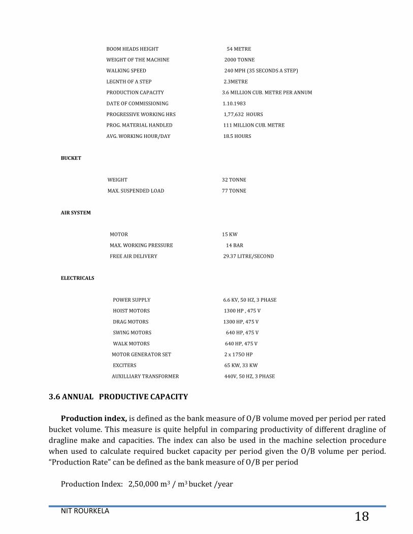
3.6 ANNUAL PRODUCTIVE CAPACITY
Production index, is defined as the bank measure of O/B volume moved per period per rated
bucket volume. This measure is quite helpful in comparing productivity of different dragline of
dragline make and capacities. The index can also be used in the machine selection procedure
when used to calculate required bucket capacity per period given the O/B volume per period.
“Production Rate” can be defined as the bank measure of O/B per period
Production Index: 2,50,000 m3 / m3 bucket /year
NIT ROURKELA 19
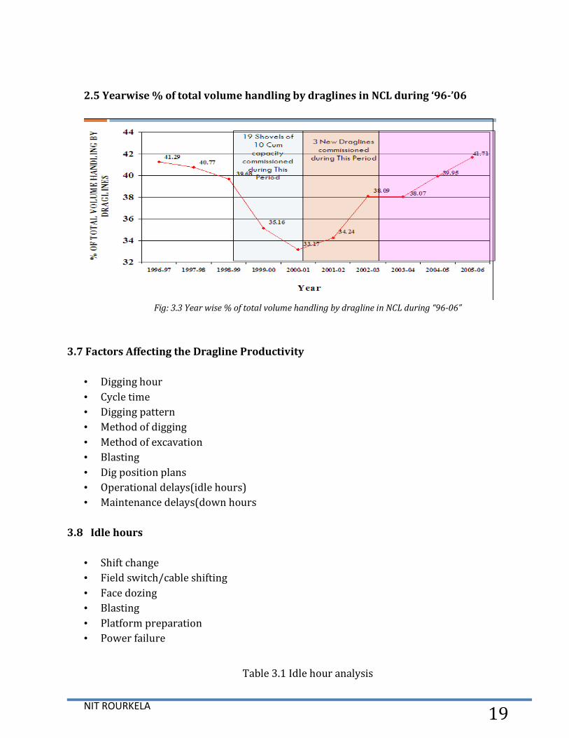
2.5 Yearwise % of total volume handling by draglines in NCL during ‘96-’06
Fig: 3.3 Year wise % of total volume handling by dragline in NCL during “96-06”
3.7 Factors Affecting the Dragline Productivity
• Digging hour
• Cycle time
• Digging pattern
• Method of digging
• Method of excavation
• Blasting
• Dig position plans
• Operational delays(idle hours)
• Maintenance delays(down hours
3.8 Idle hours
• Shift change
• Field switch/cable shifting
• Face dozing
• Blasting
• Platform preparation
• Power failure
Table 3.1 Idle hour analysis

NIT ROURKELA 20
3.9 Cycle time
One cycle time consists of
1. Drag to fill
2. Hoist & swing to dump
3. Dump
4. Lower & return swing
5. Position bucket
Cycle time 24/96 dragline at rated parameters at 1200 swing angle, 50 metre depth, 38
metre dump height
= 67.21 seconds
If the swing cycle time is reduced by one second, dragline productivity increases by
90,000 m3 /year i.e. 2.5% increase in productivity
3.10 Factors Affecting Cycle Time
Material characteristics
Bank preparation
Digging depth
Hoisting height
Swing angle
Rope & swing speeds
Operator’s proficiency
Equipment placement & scheduling

NIT ROURKELA 21
Slope of digging face
3.11 To Reduce Cycle Time of dragline
Sharp bucket teeth and shroud increases bucket fill factor, reduces bucket fill time
A well balanced light weight bucket
Good pick up and carry angle – reduces spillage
Digging in systematic pattern
A good carrying angle and hoisting under boom prevents tight lining, reduces bucket fill
time by increase hoist speed
3.12 Maximizing payload is dependent upon the following:
Geological condition mines
Blasting (blasting pattern, types of explosive)
Monitor weighing accuracy
Engage location from the dragline
Disengage Location
Rigging mechanism
Suspended load of bucket
Bucket characteristics (cutting & penetration)
Operator capability (operator skill)
Minimizing rehandle of overburden
3.13 Dig rate
Swing angle more than 120o decrease by 15 %
When cleaning the terrain to be excavated -decrease by 10%

NIT ROURKELA 22
When damp to be excavated – decrease by 10%
With oversize content – decreases by 10-15%
With re-excavation –increase by 10%
With top cutting – rocks decrease by 10-15%
3.14 Digging pattern
Walk up on digging face
45o digging face
Systematic bucket spotting
Reduce bucket fill length
Pushing in the roll of materials
Control bucket depth
Follow the previous operator’s pattern
3.15 Method of Digging
Box cut
Key cut
Strip cut
Chop down cut
Ramp cut
3.16 Chop down cut
produces only 75 % of conventional cut
low bucket fill factor
increased drag time to fill
increased dozer work
increased down time
increased repair cost
NIT ROURKELA 23
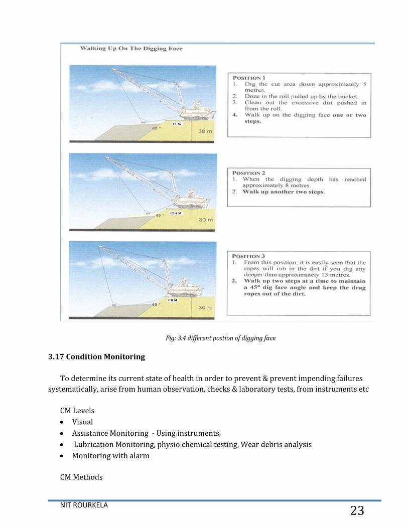
Fig: 3.4 different postion of digging face
3.17 Condition Monitoring
To determine its current state of health in order to prevent & prevent impending failures
systematically, arise from human observation, checks & laboratory tests, from instruments etc
CM Levels
Visual
Assistance Monitoring - Using instruments
Lubrication Monitoring, physio chemical testing, Wear debris analysis
Monitoring with alarm
CM Methods

NIT ROURKELA 24
Visual
Potential Failure effects Monitoring
Performance Monitoring
Fore casting
Rubbing effects:
Particle effects: Lubricant Analysis
Wear debris analysis
Chemical effects: Element Monitoring
Dynamic effects:
Shock pulse monitoring
Vibration Analysis
Noise Monitoring
Physical effects:
NDT
Temperature effects: Thermography
Electrical effects:
• Condition Monitoring is done every 6 months by Separate a Cell at Jayant
• Detailed report system wise is submitted to the all levels
3.18 Analysis Methods
They are categorized into 4 areas, as outlined
Motion analysis
Characteristics of Electrical motor - Current/ Voltage (Torque/ Speed) curves.
Short term measurements / High speed :- Motion rates (Drag, hoist, and swing operation
individually) with a step change in operator reference from full stop position
Cycle analysis
Dragline Cycle times, such as fill time, swing time, dump time, return time.
Hoist dependent swings operation of dragline.
Payload weight of bucket.
Production demographics analysis

NIT ROURKELA 25
Production rate per dig hour of dragline
Total target vs. production.
Qualitative analysis of dragline
interview / Survey operator
Fig; 3.5 demographics analysis
3.19 Dragline operation in tandem-vertical and tandem horizontal mode
Vertical tandem mode having the following conditions:
1. Thickness of over burden that are removed by dragline is more than the digging depth.
2. When used in vertical tandem mode Bench height keep limited by drilling depth
3. When increased rate of coal exposure of open cast mine, it is necessary to required
thickness of bench always less than of dragline.
Table 3.2 Machine parameters and Key field parameters that are used to make balancing diagram
of vertical tandem mode of operation

NIT ROURKELA 26
Advantages Horizontal tandem mode operation of dragline as compared to vertical
tandem mode of operation of dragline
1. In horizontal tandem mode of operation increased width of the dragline cut due to this
reduce idle time for marching and power shut down of dragline.
2. Better supervision of concentrated area of operation of both draglines due to this is
possible in this mode of operation of dragline.
3. In this mode of operation increase over burden bench thickness of overburden, dumping
height of overburden material for the lagging dragline, which is exposing coal easily, poses
no any problem.
4. Less swing angle and less problem of dumping height this increase the productivity.
Table 3.3Horizontal tandem mode, Weighted and overall cycle time for 24/96 lagging dragline
Abhimanyu (LaHT-D/L) and rehandled muck (loose over burden) for mine.

NIT ROURKELA 27
Table 3.4 Machine parameters and Key field parameters that are used to make balancing diagram
of horizontal tandem mode of operation.
3.20 Method of Excavation
• simple side casting
• advance bench excavation
• extension bench excavation
• pull back excavation
• box cut excavation
• tandem excavation
In the field study, it can be concluded that single dragline operation without rehandling is the
preferable method if the production requirement can be satisfied. However if large production
desired and extended bench method with single dragline adopted than tandem operation of
dragline may be seriously considered. However this will entail capital expenditure on the
purchase of a second dragline but the substantial savings which will result in terms of cost per
tones of coal exposed will ultimately result in better economy for the mine.

NIT ROURKELA 28
Chapter 04
Drive Technology of a Dragline in Open Cast Mines

NIT ROURKELA 29
4.1 Variable Speed drives in dragline
Variable speed drive used in dragline operation for increasing the efficiency and life time of the
dragline, different type of drive system used such as SCR based, IGBT based etc. Variable speed
drives (VSDs) with PLC controller are used to smoothly start large motors and continuously
adjust the speed according to loading condition of machine. DC motor, Induction and
synchronous motors driving conveyors, excavators use VSDs to provide high power, good
controlling, adjustable speed control, as well as regenerative breaking used to regenerate
significant amount of energy. Mechanical system used such as throttling valves, gears, or
turbines, to control speed and flow this can be replace by electric drives. Electric drive having no
moving parts, they provide very high reliability.
4.2 Advantage of variable drive system
1. Increased Reliability of the system
2. Good Control over dragline
3. Significantly Less Maintenance
4. Soft Starting of motor , generator or M-G set and Improved Power Factor
5. Cost savings of control system
6. Smooth motor starting.
4.3 Methods of speed control
The speed of the motor change with respect to driven load and according to the operating
performing. Electric motors and generator (M-G set) coupling combinations used for altering the
speed control "Speed Source" or a "Torque Source". Two types of control used in motor.
When driven load is driven at a constant speed independent of load torque is called
"Speed Source" controller.
Where the driven load is driven by a constant torque and the speed alters to the point
where the torque of the driven load equals the torque delivered by the motor is called
"Torque Source" controller.
When used in closed loop controllers employ a feedback loop to convert a "Torque Source"
into a "Speed Source" controller.
4.4 Ruggedized DC-EXX Modules
The Ward Leonard system used in dragline to control the speed of M-G set. In this system of DC
motor speed control done by two basic means of control system.
1. Generator output voltage ( a u ) control system

NIT ROURKELA 30
In this mode of operation, the drive motor current fm i is kept constant and generator field
current fg i value is changed so that output voltage (a u) varies. Hence speed rises to the base
speed. In this mode of operation torque can be maintained constant during operation.
2. Drive motor field current ( fm i ) control system
When weakening the field current of the drive motor, the speed of motor rises greater that the
base speed. In this mode of operation time output (a u) is kept constant and the drive motor (fm
i) field current is decreased and motor speed increase. Hence Armature current is constant.
Torque decreases as speed increases because torque inversely proportion to speed .
Fig: 4.2 Drive motor field current
In this mode of control system in dragline adjustments can be done at the same time or
separately. When altering the excitation power of the generator resultant in speed changes from
zero speed to base speed. In this type of arrangement usually prime movers run on a constant
speed, when lowering the excitation current of the DC motor raise the DC motor speed of the
motor.
4.5 DC Converter
220-440 V 3-phase ac input supply used by using auxiliary transformer.
300-600 V dc output by using reactifer.
350 or 750 Amp output current capacity of the system.

NIT ROURKELA 31
Fig; 4.3 Dragline M-G set
Fig; 4.4 Different mode of control of dragline drive system
4.6 Regenerative Braking of dc motor
Mechanical breaking systems convert kinetic energy into heat, usually break shoe by friction.
Regenerative braking use their drive motors to convert kinetic energy into electromagnetic
energy. Motors and generators operate under the same principle and can be used
NIT ROURKELA 32
interchangeably. Regenerative braking is done when the generated energy in breaking time is
supplied to the source. Necessary condition of regenerative breaking shows in this this equation:
E > V and negative Ia.
And back EMF, E= NP ΦZ/60A
Where, Φ flux, P no. of pole, N speed in rpm, Z no. of conductor, A no. of parallel pat, Speed of
a motor can be controlled by.
Voltage of Armature control.
Field flux control of DC motor.
Armature resistance control by using external rheostat.
The field flux of motor can’t be increased beyond a rated value (base value) so the regenerative
braking of DC motor is possible only when the speed of motor is higher than the rated value of
speed.
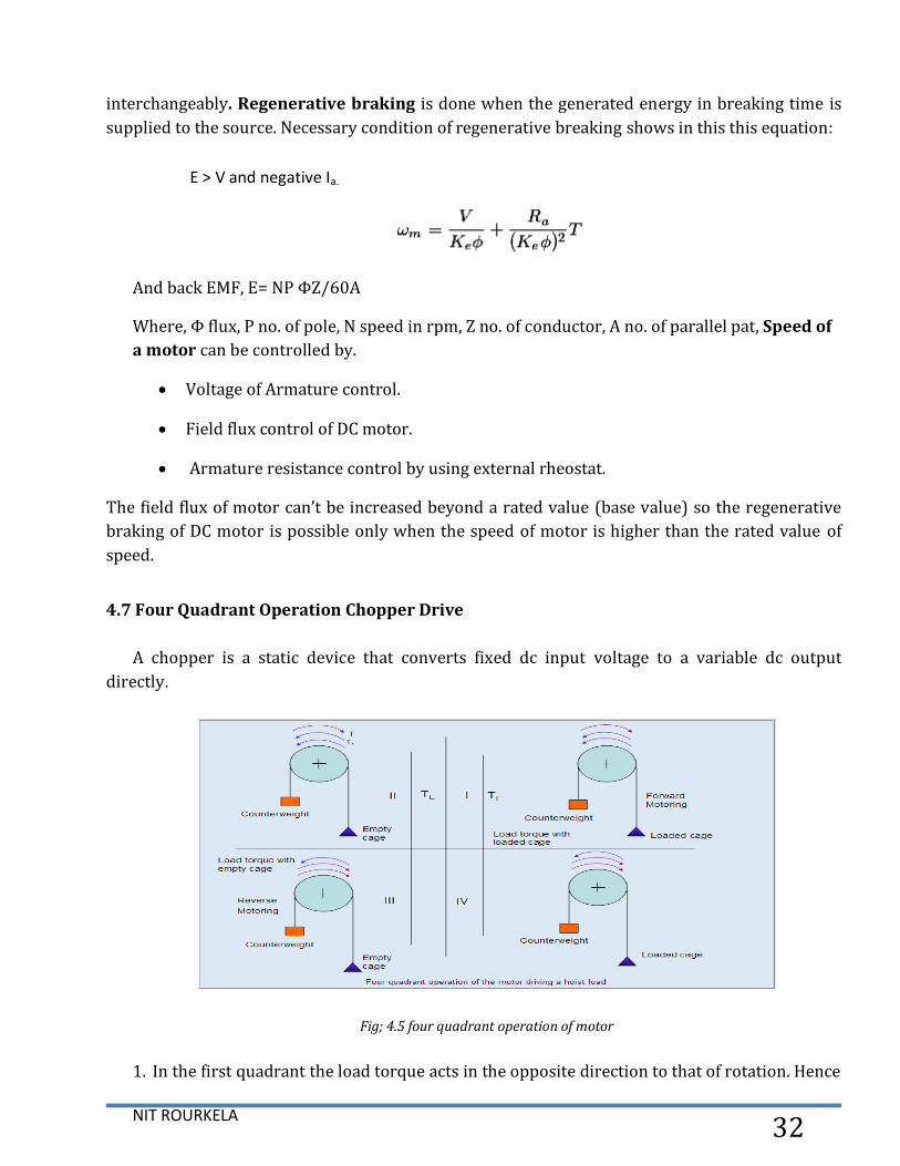
4.7 Four Quadrant Operation Chopper Drive
A chopper is a static device that converts fixed dc input voltage to a variable dc output
directly.
Fig; 4.5 four quadrant operation of motor
1. In the first quadrant the load torque acts in the opposite direction to that of rotation. Hence

NIT ROURKELA 33
to drive the loaded hoist up, the motor developed torque must be in the direction of the
rotation or must be positive. The power will also be positive so, this quadrant is known as
‘forward motoring mode’. In the first quadrant the load torque acts in the opposite
direction to that of rotation.
2. The hoisting up of the unloaded cage is represented in the second quadrant. As the
counterweight is heavier than the empty cage, the speed at which hoist moves upwards
may reach a very high value. To avoid this, the motor torque must act in the opposite
direction of rotation or motor torque must be negative. The power will be negative though
the speed is positive, so this quadrant is known as ‘forward braking mode’.
3. The third quadrant represents the downward motion of the empty cage. Downward
journey will be opposed by torque due to counterweight and friction at the transmitting
parts, move cage downwards the motor torque in the direction of the rotation. Electric
machine acts as a motor but in the reverse direction compared to first quadrant. The
torque is negative as speed is increased in the negative direction, but the power is positive,
this quadrant is known as ‘Reverse motoring mode’.
4. Fourth quadrant has the downward motion of the loaded cage. As loaded cage has more
weight than the balanced weight to limit the speed of the motion, motor torque must have
opposite polarity with respect to rotation and acts as a brake. The motor torque sign is
positive, but as speed has negative direction; the power will be negative, this quadrant is
designated as ‘Reverse braking mode’
4.8 AC Technology
The main components of an AC drive are used to able the required level of current and
voltage. The controls have to be able to provide the user with necessary adjustments such as
minimum and max limit of speed settings, so that the drive can be adapted to the user's process
and aureate control.
AC drives can be classified as current-controlled AC drives and voltage-controlled AC drives.
Vector control and direct torque control belong to the current- controlled AC drives while V/f
control and the proposed AC WLDS belong to the voltage-controlled AC drives. Similarly to AC
dives, the inverters in smart grid integration can be current-controlled or voltage-controlled

NIT ROURKELA 34
Fig; 4.6 Experimental setup drives
4.9 AC Main Motion Drive Motors
In dragline, AC squirrel-cage inductions motors power swing, drag, hoist, and propel
motions are used.
Built in speed sensor are used so that it’s replaceable without removal of motor from
service can be easily done.
Fig 4.7 Diagnosis system of dragline, IGBTs-switching, voltage sensor and delay times compensation on the fault
detection signal in different condition

NIT ROURKELA 35
4.10 Barriers to AC
Evolutionary upgrades with analog and digital control of drive system in dragline
AC drive provide reliable operation but limited
Efficiency of ac drive system
Productivity increase
Low Maintenance required
Operating costs reduce
Strict utilities requirements on allowable voltage fluctuation, power factor at the PCC and
levels of harmonic injection
This can be overcome with Active Front Ends (AFEs) in place of normal rectifiers. This
makes static AC drives a superior alternative to M-G set drives.
4.11 AC Gearless Dragline
Introduction – Configuration
Replace multiple Hoist / Drag gears and DC motors with single synchronous gearless
motor connected directly to the drum
All M-G sets and gears for Hoist and Drag are eliminated
Use geared static AC drives for Swing and Propel
All M-G sets for the Swing are eliminated
4.12 AC Conventional Dragline
Introduction - Configuration

NIT ROURKELA 36
Replace multiple Hoist / Drag DC motors with AC induction motors.
Replace multiple Swing / Propel DC motors with AC induction motors
All M-G sets are eliminated
4.13 Advantage of AC convention drive
1. A key performance requirement of each of these configurations is that the machine must
be able to obtain 0.80 leading power factor at the high voltage slip rings on the machine at
the machines nominated peak power level. It is important to verify that the AC drive will
be capable of sustaining a minimum VAR capability to achieve 0.80 leading power factors
at the 22 kV incomer terminals of the machine on a consistent repeatable basis for the
duration of the machine life with a modulation index of less than 1.00.
2. A: Modulation Index is defined as:
3. The drive systems can provide up to 0.8 leading pf at peak load at slip rings
4. Auxiliary load is typically 3.0 MVA with 0.8 lag pf
5. The peak load of the drives is 24.5 MW
6. 7/7/8 uses 30 AFEs with a modulation index of 0.89 to achieve 0.8 leading power factor.
Fig; 4.8 Drive control system of AC Conventional drive
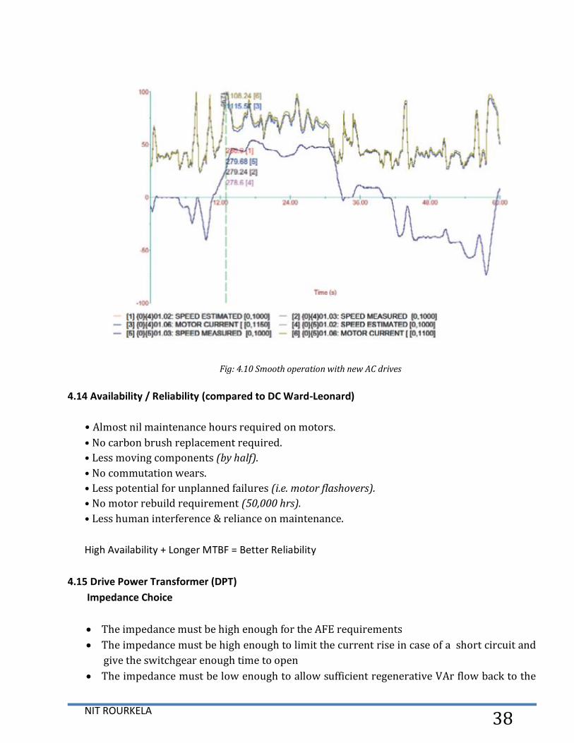
Thanks to quick and accurate drive control with reliable feedback it was possible to realize a
very stable and smoothly operating machine without current peaks, which had been one of the

NIT ROURKELA 37
main problems with previous DC system.
Benefits
Higher reliability and lower maintenance costs
Lower losses in drive system, saving 1,2 MWh/year
Lower dynamic load – longer lifetime for gearbox and ropes
1–3 seconds shorter working cycle – 2–4% higher productivity
15 years longer lifetime for total dragline
After renovation, the dragline has an excellent dynamic performance and overload
characteristics with the speed and torque control. There is less mechanical stress and guaranteed
longer lifetime for the gearboxes. Its average productivity exceeds others by 10–40%. Also
important is its energy consumption, which is 40% less than average.
Fig.: 4.9 Principle connection of AC drive system
NIT ROURKELA 38
Fig: 4.10 Smooth operation with new AC drives
4.14 Availability / Reliability (compared to DC Ward-Leonard)
• Almost nil maintenance hours required on motors.
• No carbon brush replacement required.
• Less moving components (by half).
• No commutation wears.
• Less potential for unplanned failures (i.e. motor flashovers).
• No motor rebuild requirement (50,000 hrs).
• Less human interference & reliance on maintenance.
High Availability + Longer MTBF = Better Reliability
4.15 Drive Power Transformer (DPT)
Impedance Choice
The impedance must be high enough for the AFE requirements
The impedance must be high enough to limit the current rise in case of a short circuit and
give the switchgear enough time to open
The impedance must be low enough to allow sufficient regenerative VAr flow back to the

NIT ROURKELA 39
line
Impedance Level
A gap greater than 50mm is inserted between the primary and secondary windings and
this results in a loosely coupled system
Not all the flux from the secondary winding links the primary windings.
Most of the secondary flux closes through the gap between the primary and secondary.
Hence the high impedance is concentrated on the secondary.
This secondary leakage flux is proportional to the impedance of the transformer and
creates an inductive voltage drop under load
4.16 AC IGBT/AFE Conventional
Why Conventional?
Active Front End (AFE) using AC IGBT devices. (Proven capability - Power factor capable of
0.8 leading).
AC motors plug directly into existing style gear cases. (One-style motor required, common
to all motions).
Performance / Productivity increases.
Rugged Skid design for excavator use. (Proven reliability).
Siemens SiBAS drive control. (Proven reliability).
AC IGBT devices. (Proven reliability).
Water-cooled technology. (Proven technology in transportation).
No carbon brushes. (Reduced maintenance costs).
Complete remote diagnostic system (Full system capability).
4.17 Active Front End (features)
Reliable operation of active front end rectifier but limited with respect to maintenance,
efficiency, operating costs and productivity of dragline.
It’s providing leading Power Factor this makes Static Dragline Drives feasible.
Chopper control system in four quadrant operations is used. Hence Regenerative feedback
into the line supply easily.
Low harmonics are fed back into the supply because sinusoidal line currents.
When power fails in regenerative operation no commutation faults in this time.
Voltage fluctuations of Line supply is less as compensated.
Dynamic performance is extremely high.
Power factor up to 0.8 leading.

NIT ROURKELA 40
Fig; 4.11 Positive half cycle of operation
Fig; 4.12 Negative half cycle mode of operation
4.18 IGBT (Insulated Gate Bipolar Transistor)
IGBT used as power switches. Transistor needs only low power gating signal to turn on and
off. IGBT power modules for Active Front End (AFE), inverter with "plug-in" design. IGBT's utilize
simple, reliable, gate drivers without snubbers circuit and di/dt reactors IGBT can safely turn-off
overload currents without damage (GTO's fail if overloaded even momentarily)
High switching frequency of IGBT
Means smoother current less harmonics and ripple
Water cooled or air, no heat sink required.
Cooled and NO Fuses
IGBT: 3300 V, 1200 amp Motor voltage: 1400 V
NIT ROURKELA 41
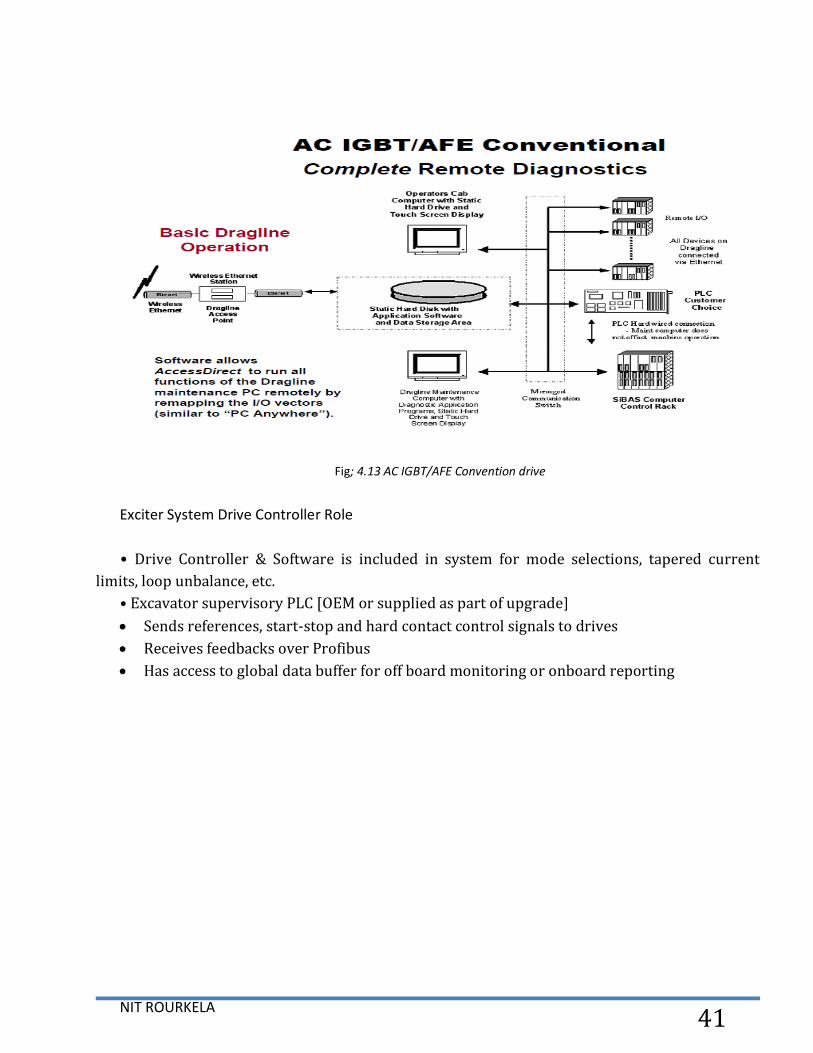
Fig; 4.13 AC IGBT/AFE Convention drive
Exciter System Drive Controller Role
• Drive Controller & Software is included in system for mode selections, tapered current
limits, loop unbalance, etc.
• Excavator supervisory PLC [OEM or supplied as part of upgrade]
Sends references, start-stop and hard contact control signals to drives
Receives feedbacks over Profibus
Has access to global data buffer for off board monitoring or onboard reporting

NIT ROURKELA 42
Chapter 05
Programmable Logic Controller (PLC)

NIT ROURKELA 43
5.1 PLC (Programmable Logic Controller)
Programmable Logic Controllers (PLC) to emulate conventional mechanical relaying schemes,
protection, annunciation functions, for used DCS system. Modern PLCs can perform many Math
and Logic Functions without additional Ladder Logic Programming
Differentiation, Integration
+, -, *, /
Boolean Logic Functions (AND, NOT, OR)
Master Control Functions (Reset, etc)
Fig: 5.1 PLC based Dragline Control
All drives and other devices are controlled by a PLC based system. The digital control system
has been fully integrated with an extensive machine diagnostics package and touch-screen
controls to speed maintenance work, increase operation efficiency and reduce down-time.
Essential Part of Motor Control Protect against:
Under Voltage

NIT ROURKELA 44
Over Voltage
Maintain Frequency range (AC Machines Only)
Over Current
Over Heating
Over Speed
Over Load
5.2 PLC system of Dragline Lube Control
Lube System Control timers and Conventional relays can be replaced with PLC systems in
dragline which provide improved reliability/repeatability and monitoring of signal along with
ease of system with different stage of modifications.
5.3 PLC Scan
The PLC program is executing the input form CPU and performs communication and
internal diagnostics and finally updates the status of outputs. This process repetitive referred to
as a scan.
Fig: 5.2 PLC Scan

NIT ROURKELA 45
5.4 Memory used in PLC system having 3 types
1. Read Only Memory (ROM) is types of memory used were it is necessary to protect
data or programs from accidental erasure.
2. Random Access Memory (RAM) RAM is used as a temporary storage area. RAM is
memory that allows data to be written to and read from any address (location).
RAM is volatile, meaning that the data stored in RAM will be lost if power is lost
3. Erasable Programmable Read Only Memory (EPROM) provides a level of
security against unauthorized or unwanted changes in a program. EPROMs are
designed so that data stored in them can be read, but not easily altered. Changing
EPROM data requires a special effort. UVEPROMs (ultraviolet erasable
programmable read only memory) can only be erased with an ultraviolet light.
EEPROM (electrically erasable programmable read only memory), can only be
erased electrically.
5.5 Basic Components of PLC:-
Actuators
Discrete Inputs and Outputs
Central processor unit (CPU)
Ladder Logic Programming
Power Supply System
Input / Output Module System
Programming Device
Time
Fig: 5.3 General view of PLC system
5.6 Basic Operation of PLC system in dragline:-

NIT ROURKELA 46
The basic operation of PLC is given by 3 steps.
1. Read the input from field status used devices such as sensor, transducer
2. Solving or Execution the logic from input,
3. Updating the output status shown on the screen of diagnostic system
Fig: 5.4 Operation of a PLC System
5.7 PLC Input and Output Devices of dragline:-
Two type of system used in input output device
1. Digital - binary system used in input / output devices which must be in one of the two
states: on or off. Digital system such as relay, solenoid valves, motor starter etc.
2. Analog - continues devices - sense and respond to set the range of values in input / output
device. Analog system such as valve position, air pressure, motor speed etc.
5.8 PLC Special Features
• Time Delay Relays
• Counter Relays
• Special Functions
• User Defined Functions
• Special Bits
5.9 Time Delay Relays

NIT ROURKELA 47
• When TD Relay Pick-Up Coil is Energized, a Delay is Initiated
• Normally Open Contacts Wait to Close until Delay is Completed
• Normally Closed Contacts Wait to Open until Delay is Completed
• Very Useful for Creating a Sequence of Control Events
5.10 Counters
• Counter Relays must “Count” a pre-determined number of events before changing contact
status
• Can Count Up (Up Counter) or Count Down (Down Counter)
• e.g. An Up Counter is set to 8 and is programmed to detect every occurrence of a 5 Volt
pulse. When it has detected 8 such occurrences, the NO Contacts close and the NC contacts
open.
5.11 Functions of controllers
Great for making Real-Time Clocks, etc
on-off control,
sequential control,
feedback control, and
motion control
Direct Torque Control (DTC) significantly increases pull and drags forces and provides
greater performance and constant power capability. Because of the high requirements of low
harmonics (Voltage THD <5 %) and the voltage fluctuation of a weak grid, an active rectifier
solution was used. In addition, when lowering the bucket, recovered braking energy is returned
to the network. All drives and other devices are controlled by a PLC based system.
Benefits
Higher reliability and lower maintenance costs
Lower losses in drive system, saving 1,2 MWh/year
Lower dynamic load – longer lifetime for gearbox and ropes
1–3 seconds shorter working cycle – 2–4% higher productivity
15 years longer lifetime for total dragline
5.12 Alarm System
Alarming allows for exception based reporting on events desired by programming of PLC.
Alarms system can only be built on information sets contained in PLC in different

NIT ROURKELA 48
parameter of dragline such as hoist motor, hoist generator, swing motor, swing generator,
drag motor generator set, propel M-G set, fan, blower and lighting system of dragline.
Alarms can’t be changed without changing underlying PLC code.
Fig: 5.5 Alarm system of dragline with diagnostic system
Fig: 5.6 diagnostic screen of dragline

NIT ROURKELA 49
Fig; 5.7 PLC Software (RSLogix 500) - Commercial
5.13 Integrated Support Centers (ISCs)
This has allowed some operations to go far beyond the basic production style report, and
hence, are able to make more informed decisions. In addition, coupling these tools with high-
speed Internet services between mine sites has further created an environment where multiple
machines and sites can be monitored in real-time from anywhere in the world.
Integrated Support Centres (ISCs) provide:
Leveraging capability to get more out of key content experts
Better collaboration between personnel and sites across organizations and continents
Greater standardization, compliance, and predictability of operations
Faster response times to issues
Better deployment of company resources based on more holistic views of the entire
operations and its priorities
Improved benchmarking accuracy across different operations
Ultimately, reduced cost and improved financial, safety, and environmental performance
The establishment of the ISC required the following components:
Ethernet based monitoring equipment and sensors that are capable of being remotely
accessed, monitored and configured.
Establishing correct routing and security profiles to make data available off-board the
NIT ROURKELA 50
machine
Providing sophisticated data propagation technologies for data and vision systems to reduce
network bandwidth loads
Creating site-to-site VPN network bridges to connect the ISC to corporate client networks,
and to the individual machines
Leveraging from VOIP technologies.
The ISC allows:
Leveraging of our key product experts and dragline/ shovel experts to resolving issues
A proactive and faster response times to incidents
Better standardization between our installations
Greatly enhanced visibility of the performance and reliability of our equipment
Significantly improved ability to deploy company resources to the best result for end users.

NIT ROURKELA 51
Chapter 06
TRAILING CABLES OF DRAGLINE

NIT ROURKELA 52
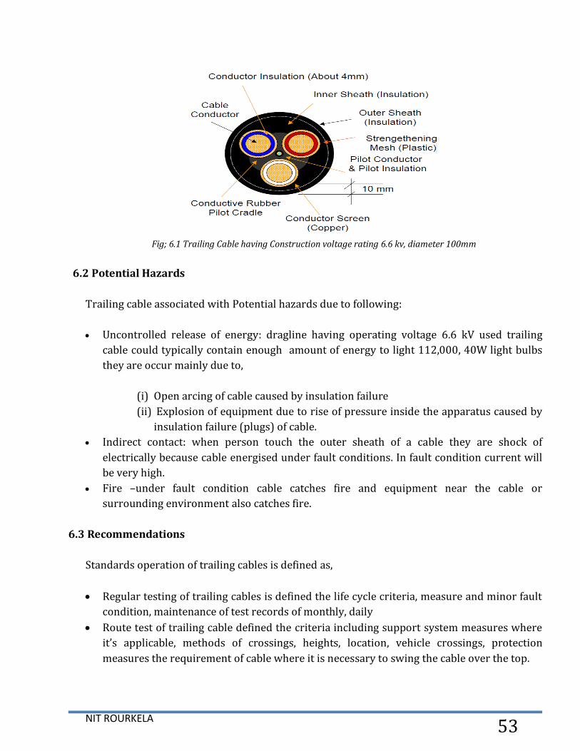
6.1 Construction Trailing Cable
The high voltage trailing cable used to supply the electrical power of dragline. Main
components of the trailing cable and their function is given as:
Conductor of cable; Stranded Copper and bundled conductor are used that deliver the
electrical power to the dragline. Area of conductor about 120-mm sq. and diameter is
about 15.6mm.
Insulation of Power Conductor; insulating material used in rubber compound designed to
withstand high voltage about (6.6kv).
Separator Cradle; A cradle separator that carries the pilot wire in the center of power
conductor. In power conductor design having hole in center of conductor.
Metallic Screens; each conductor is surround by earth metallic screens completely and
carry the fault current when any type of fault occur in the cable.
Pilot Wire;. Pilot wire used in protection of cable by used in relay to detect the fault in the
cable.
Sheath; sheath having used hard wearing material, tough durability, designed to separate
the external environment from the conductors and able to withstand the physical,
chemical, environmental, weather condition.
Semi-conductive tape: tape to be used to separate the insulation from the conductors
when the rating of the cable is greater than 3.3 kv.
NIT ROURKELA 53
Fig; 6.1 Trailing Cable having Construction voltage rating 6.6 kv, diameter 100mm
6.2 Potential Hazards
Trailing cable associated with Potential hazards due to following:
Uncontrolled release of energy: dragline having operating voltage 6.6 kV used trailing
cable could typically contain enough amount of energy to light 112,000, 40W light bulbs
they are occur mainly due to,
(i) Open arcing of cable caused by insulation failure
(ii) Explosion of equipment due to rise of pressure inside the apparatus caused by
insulation failure (plugs) of cable.
Indirect contact: when person touch the outer sheath of a cable they are shock of
electrically because cable energised under fault conditions. In fault condition current will
be very high.
Fire –under fault condition cable catches fire and equipment near the cable or
surrounding environment also catches fire.
6.3 Recommendations
Standards operation of trailing cables is defined as,
Regular testing of trailing cables is defined the life cycle criteria, measure and minor fault
condition, maintenance of test records of monthly, daily
Route test of trailing cable defined the criteria including support system measures where
it’s applicable, methods of crossings, heights, location, vehicle crossings, protection
measures the requirement of cable where it is necessary to swing the cable over the top.

NIT ROURKELA 54
Chapter 07
COMPUTER AIDED DESIGN, MODELLING AND
ANALYSIS OF BULL GEAR OF A DRAG LINE

NIT ROURKELA 55
7.1 Modelling Procedure of Bull Gear
Modeling and drafting of bull gear is done in pro-e software. The various tools used for
modeling of bull gear is revolve, extrude, chamfer, round, pattern. Various steps in modelling are
as follows:
Sketch dedendum circle and then extrude.
Sketch the one teeth profile and then extrude.
Pattern the teeth.
Sketch one arm of gear and then extrude.
Pattern the arm.
Sketch the one hole.
Pattern the holes.
Fig; 7.1 Modelling of Bull Gear

NIT ROURKELA 56
Fig: 7.2 Drafting of Bull Gear
7.2 FINITE ELEMENT APPROACH
Finite Element Methodology
Finite element method always follows a step by step process. The process is given as,
Step 1: Discretization of the Structure of the modal.
Step 2: Selection of Displacement Model or Proper Interpolation.
Step 3: Derivation of the Element Stiffness Load Vectors and Matrices
Step 4: Overall Equilibrium Equations by Assemblage of Elemental Equations.
Step 5: Solution for the Unknown Nodal Displacements solution is obtain.
Step 6: Elemental Stress and Strains is commutated.
The general steps followed in a finite element analysis with a commercial FEM package is as
shown below:
Fig; 7.3 Computer Aided Modeling of Bull Gear
7.3 Rigging mechanism
Dragline bucket is mounted on the boom with supporting wire ropes. Bucket movement
depend on the number of ropes and chains, it is called rigging mechanism. This mechanism
mainly consist of the ballasts the bucket. Also, wire ropes support the horizontal and vertical

NIT ROURKELA 57
movements of the bucket of the dragline. Bucket and rigging mechanism classified into four
groups:
Optimization of bucket filling of dragline
Testing of bucket kinematically
Improvement of rigging system
Automation of the scooping.
Data from Dragline Abhimanyu dragline 24/96, NCL Singrauli Amlori Project different part of
bucket is given as,
Fig: 7.4 Elements of Dragline Bucket and Rigging Mechanism
Table 7.1 part of dragline bucket
NIT ROURKELA 58
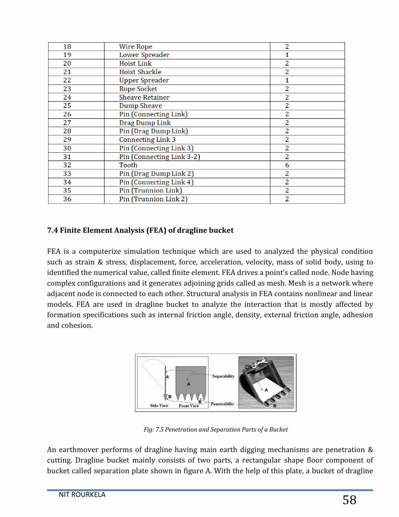
7.4 Finite Element Analysis (FEA) of dragline bucket
FEA is a computerize simulation technique which are used to analyzed the physical condition
such as strain & stress, displacement, force, acceleration, velocity, mass of solid body, using to
identified the numerical value, called finite element. FEA drives a point’s called node. Node having
complex configurations and it generates adjoining grids called as mesh. Mesh is a network where
adjacent node is connected to each other. Structural analysis in FEA contains nonlinear and linear
models. FEA are used in dragline bucket to analyze the interaction that is mostly affected by
formation specifications such as internal friction angle, density, external friction angle, adhesion
and cohesion.
Fig: 7.5 Penetration and Separation Parts of a Bucket
An earthmover performs of dragline having main earth digging mechanisms are penetration &
cutting. Dragline bucket mainly consists of two parts, a rectangular shape floor component of
bucket called separation plate shown in figure A. With the help of this plate, a bucket of dragline
NIT ROURKELA 59
is able to move the overburden by pushing or dragging (dragline bucket). Secondly, the bucket
having another mechanical component which is called teeth, shown in figure B. Bucket teeth
penetrate the overburden material to release digging mechanism. In a dragline combination of
rope and chain gives the axial motion of the bucket and also determine the digging direction of
the dragline bucket.
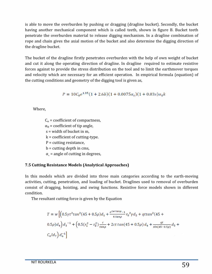
The bucket of the dragline firstly penetrates overburden with the help of own weight of bucket
and cut it along the operating direction of dragline. In dragline required to estimate resistive
forces against to provide the stress distribution on the tool and to limit the earthmover torques
and velocity which are necessary for an efficient operation. In empirical formula (equation) of
the cutting conditions and geometry of the digging tool is given as,
Where,
Cₒ = coefficient of compactness,
α₀ = coefficient of tip angle,
s = width of bucket in m,
k = coefficient of cutting-type.
P = cutting resistance,
b = cutting depth in cms,
α˛ = angle of cutting in degrees,
7.5 Cutting Resistance Models (Analytical Approaches)
In this models which are divided into three main categories according to the earth-moving
activities, cutting, penetration, and loading of bucket. Draglines used to removal of overburden
consist of dragging, hoisting, and swing functions. Resistive force models shown in different
condition.
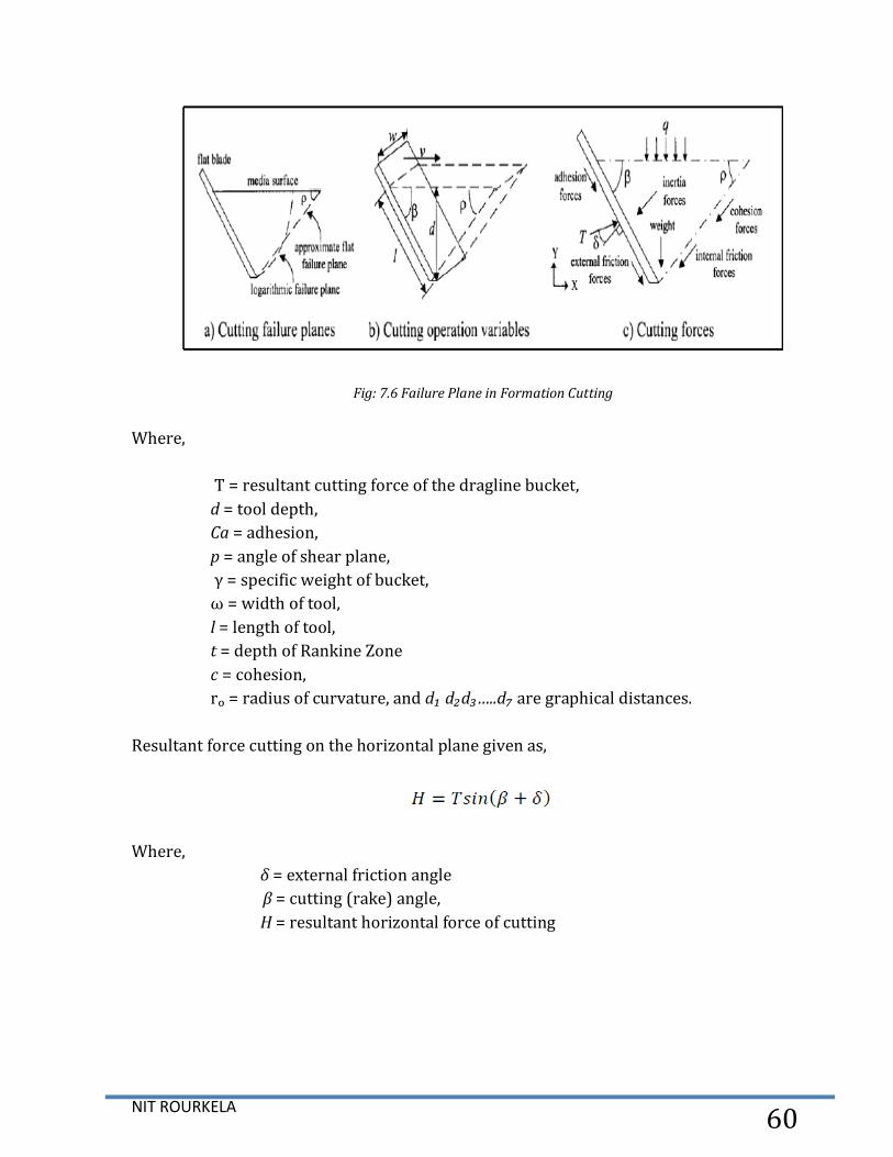
The resultant cutting force is given by the Equation
NIT ROURKELA 60
Fig: 7.6 Failure Plane in Formation Cutting
Where,
T = resultant cutting force of the dragline bucket,
d = tool depth,
Ca = adhesion,
р = angle of shear plane,
γ = specific weight of bucket,
ω = width of tool,
l = length of tool,
t = depth of Rankine Zone
c = cohesion,
rₒ = radius of curvature, and d₁ d₂d₃…..d₇ are graphical distances.
Resultant force cutting on the horizontal plane given as,
Where,
δ = external friction angle
β = cutting (rake) angle,
H = resultant horizontal force of cutting
NIT ROURKELA 61
Chapter 08
RESULTS AND DISCUSSION
NIT ROURKELA 62
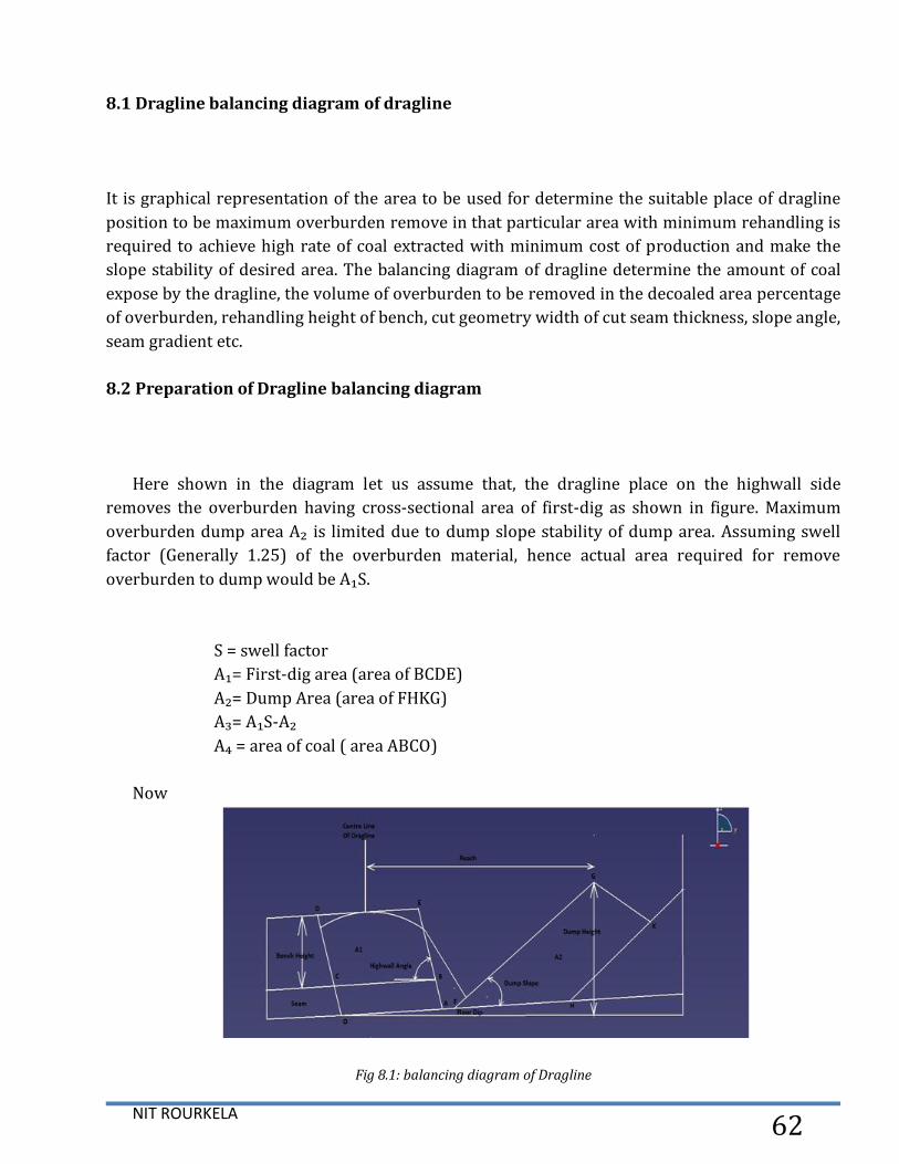
8.1 Dragline balancing diagram of dragline
It is graphical representation of the area to be used for determine the suitable place of dragline
position to be maximum overburden remove in that particular area with minimum rehandling is
required to achieve high rate of coal extracted with minimum cost of production and make the
slope stability of desired area. The balancing diagram of dragline determine the amount of coal
expose by the dragline, the volume of overburden to be removed in the decoaled area percentage
of overburden, rehandling height of bench, cut geometry width of cut seam thickness, slope angle,
seam gradient etc.
8.2 Preparation of Dragline balancing diagram
Here shown in the diagram let us assume that, the dragline place on the highwall side
removes the overburden having cross-sectional area of first-dig as shown in figure. Maximum
overburden dump area A₂ is limited due to dump slope stability of dump area. Assuming swell
factor (Generally 1.25) of the overburden material, hence actual area required for remove
overburden to dump would be A₁S.
S = swell factor
A₁= First-dig area (area of BCDE)
A₂= Dump Area (area of FHKG)
A₃= A₁S-A₂
A₄ = area of coal ( area ABCO)
Now
Fig 8.1: balancing diagram of Dragline

NIT ROURKELA 63
1. Condition (A₃<0)
In this condition dump area is not capable of accommodating OB more than the available first-
dig quantity, hence overburden rehandling is required.
2. Condition (A₃=0)
In this condition indicates an optimum solution (balance condition) of overburden removal
and in this condition having maximum coal expose with minimum cost. In this condition no
overhandling is required.
3. Condition (A₃>0)
In this condition dump area is not capable to taking the loose material of first-dig completely and
A3 amount of overburden material would be left as residual. This residual material can be
removed by two ways,
Transporting of dump material and dump to another place by using dumper.
Extra dump capacity generating this can be increased by increasing reach. In this
condition Extended bench method are used.
8.3 Calculation of annual output, operating cost, ownership, and cost per tonne of coal
exposed in dragline in Amlori project NCL Singrauli open cast mine.
Estimating Dragline Production
A basic approach to estimating the dragline production of Amlori project NCL Singrauli
open cast mine use of a standard cycle excavator equation that are used to calculate monthly
dragline output is,
Where,
O= output (bcy/month)
B= bucket size of dragline (yd)
A= maintenance availability (%)
BF= bucket fill factor of dragline
HS= hour scheduled /month

NIT ROURKELA 64
S= swell factor of overburden material / 100
C= average cycle time of bucket (second)
R= rehandling percentage /100
J= job factor (percentage of time that stripping of overburden machine is available)
8.4 Evaluation of Availability (A) and Utilization (U)
To calculate A and U field data was required and maintained on day to day on the basis of
dragline under study.
Where,
SSH = scheduled shift hour
MH = maintenance hour
ID = idle hour
BH = breakdown hour
For, NCL Singarauli Abhimanyu Dragline (24/96)
SSH = 720, WH = 507, MH = 119, BH = 33, IH = 61
Standard cycle time (second) = 60 sec, Observed cycle time (second) = 61.7 sec
= 0.7888
NIT ROURKELA 65
= 0.7041
So, we get Availability = 0.7888
Utilization = 0.7041
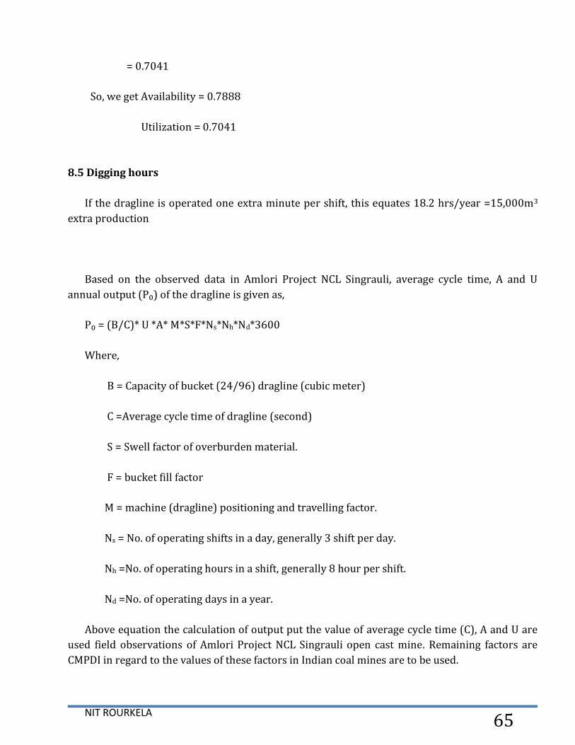
8.5 Digging hours
If the dragline is operated one extra minute per shift, this equates 18.2 hrs/year =15,000m3
extra production
Based on the observed data in Amlori Project NCL Singrauli, average cycle time, A and U
annual output (P₀) of the dragline is given as,
P₀ = (B/C)* U *A* M*S*F*Ns*Nh*Nd*3600
Where,
B = Capacity of bucket (24/96) dragline (cubic meter)
C =Average cycle time of dragline (second)
S = Swell factor of overburden material.
F = bucket fill factor
M = machine (dragline) positioning and travelling factor.
Ns = No. of operating shifts in a day, generally 3 shift per day.
Nh =No. of operating hours in a shift, generally 8 hour per shift.
Nd =No. of operating days in a year.
Above equation the calculation of output put the value of average cycle time (C), A and U are
used field observations of Amlori Project NCL Singrauli open cast mine. Remaining factors are
CMPDI in regard to the values of these factors in Indian coal mines are to be used.

NIT ROURKELA 66
Table: 8.1 Productivity factors for dragline as per CMPDI recommendations
For, NCL Singarauli Abhimanyu Dragline (24/96)
P₀ = (24/61.7)* 0.719*0.555*0.8*0.733**8*3*365*60*60
= 2.80 M cu.m.
So, the annual output of Abhimanyu dragline in Amlori Project NCl Singrauli is 2.80 M cu.m.
8.6 Computation of Efficiency of Draglines
The efficiency of dragline was calculated by using the following formula.
The determine the annual output of dragline it is necessary to prepared the balancing
diagram of horizontal tandem and vertical tandem modes of operation of dragline, respectively
8.7 Calculation of Coal Exposure of dragline
The total coal expose by the draglines working in different tandem mode of operation was
estimated by generalize the balancing diagram concept.
NIT ROURKELA 67
Where,
CE = Coal exposure of dragline (M te),
PFD = lagging dragline of annual output from the first dig (Mm³),
A = area of first dig (m²),
T = coal seam thickness (m),
W = cut width of dragline (m)
D = specific gravity of coal to be extracted,
R = recovery factor.
The term (PFD/A) represents the annual linear advance of the draglines
8.8 Estimation of Operating Cost
The Cost calculation has been made on the basis of information supplied by NCL Singrauli
Amlori Project.
Approach to the problem
No. of annual working day- 300
No. of daily shift- 3
Duration of each shift- 8 (hour)
No. of operators for dragline in each shift- 2
No. of helper- 1
Oilers, Electrician and Mechanics are including in maintenance cost.
Calculation of Operating Cost and Ownership of Abhimanyu dragline in Amlori project NCL
Singrauli,
1. Cost of Ownership per year of 24/96 dragline
(a) Equipment Cost
Cost of Abhimanyu dragline (24/96) = Rs.160 crore
(b) Depreciation Cost of Abhimanyu dragline 25 year i.e. annual flat rate of 4%
Annual depreciation cost of Abhimanyu dragline (24/96) = Rs. 6.4 crore
(c) Annual Cost of Ownership of dragline
Average annual investment of Abhimanyu dragline
NIT ROURKELA 68
×cost of Abhimanyu dragline
= ×160 crore
= Rs. 83.2 crore
Where N = Life of dragline
(d) Insurance, annual interest, and taxes of Abhimanyu dragline i.e. annual flat rate
of 12.5%
= 12.5 % of Rs. 83.2 crore
= Rs. 10.4 crore
Hence, Total Ownership Cost per year of Abhimanyu dragline = [depreciation cost per year +
annual interest, insurance and taxes]
=Rs. [6.4 +10.4] crore
= Rs. 16.8 crore
2. Operating Cost per year of Abhimanyu dragline (24/96)
(a) Annual Manpower Cost of Abhimanyu dragline (Salary & Wages)
Operator Cost @ Rs. 0.02 crore/operator for 2 operators in 3 shift = Rs. 0.12 crore
Helper cost @ Rs. 0.01 crore for 1’ 3 = Rs. 0.3 crore
Hence, Total Manpower Cost = Rs. (0.12 + 0.03)
=Rs. 0.15 crore
(b) Annual energy and power consumption on the basis of 13.65 MKWH
Annual power consumption cost @ Rs. 4.89/KWH
Rs. 4.89×13.65 MKWH
Rs. 6.675 crore
(c) Annual lubrication Cost Abhimanyu dragline
Annual lubrication cost @ 30% of cost of consumption Abhimanyu dragline
= Rs. 2.0025 crore
(d) Annual Maintenance Cost

NIT ROURKELA 69
Annual maintenance cost of Abhimanyu dragline @ 20% of depreciation cost = Rs. 1.28
crore
Major breakdown maintenance cost @ 2% of cost of equipment = Rs. 3.2 crore
Total maintenance cost of Abhimanyu dragline = Rs. 4.48 crore
Hence, Total annual Operating cost of Abhimanyu dragline = Rs. [0.15+ 6.675+ 2.0025+
4.48]
= Rs. 13.3075 crore
Total annual ownership cost and operating cost
= Rs. [16.8+ 13.3075] crore
= Rs. 30.1075 crore
Considering annual output of 24/96 dragline as 3.4Mm³
= Rs. 88.55 per/ m³
Calculation of cost per tonne of coal exposed of Abhimanyu dragline
1. Single dragline Operation without rehandling
Amount of effective overburden handled = 3.4 Mm³.
Amount of coal exposure =
= 1.36 Mte
Estimated Cost per tonne of coal exposed =

NIT ROURKELA 70
= Rs.
= Rs. 221.37/te of coal exposed
2. Single dragline extended bench operation
Percentage of rehandling is 61.23%
Total O/B handle = O/B directly exposed coal + O/B rehandled
= O/B directly exposed coal (1+ coefficient of rehandled)
Here, Coefficient of rehandling is
Therefore, 3.4 Mm³ = O/B directly exposed coal, 1.61
Hence O/B directly exposed coal removed by the dragline = 3.4/1.61
= 2.11 Mm³
Amount of effective O/B handled = 2.11 Mm³
Amount of coal exposure =
= 0.844 Mte
Estimated cost per tons of coal exposed =
= Rs. 356.72 per tonne of coal exposed
3. Horizontal Tandem Operation
When leading and lagging dragline is deployed 24/96 having annual production of 3.4

NIT ROURKELA 71
Mm³ each
Total Ownership and Operating cost per year of two dragline (24/96 + 24/96)
= Rs. 60.215 crore
Estimated cost per tonne of coal exposed in tandem dragline operation on the basis of
average stripping ratio 2.5 m³/te
Percentage rehandling is 42.48%
Amount of effective O/B removed = 6.8Mm³/ 1.425
= 4.77Mm³
Amount of coal exposed = 4.77Mm³/2.5 m³/te
= 1.91Mte
Estimated cost per tonne of coal exposed
= Rs. 315.26 per tonne of coal exposed
4. Vertical Tandem Operation
When the leading and lagging dragline having annual production 3.4 Mm³
Percentage rehandling is 25.95%
= 5.40Mm³
= 2.16 Mte
Estimated cost per tonne of coal exposed =

NIT ROURKELA 72
= Rs. 278.77 per tonne of coal exposed
Hence, different mode of operation of dragline and estimated cost calculate.
8.9 Formula of maximum depth that can be worked by a dragline is given
Thickness of coal seam in Amlori mine in working (t) = 4.5 m
Repose angle of overburden (x) = 380
Dragline Reach of (R) = 73 m
Swell factor of overburden material (S) = 1.39
Cut width (W) = 60 m
Slope angle between horizontal to highwall (y) = 700
H = 29.74 m
So, the maximum depth in that work is done = 29.74 m

NIT ROURKELA 73
8.10 In the given data of Abhimanyu dragline (24/96) in Amlori Project NCL Singrauli ,
after calculation we get
Percentage of Availability of dragline = 78.88 % Percentage of Utilization of dragline = 70.41 %
And the maximum depth in that work is done = 29.74 m
The annual output of dragline = 2.80 M cu.m.
Table 9.1 Estimated cost of dragline in different mode of operation

NIT ROURKELA 74
Chapter 9
CONCLUSION

NIT ROURKELA 75
9. CONCLUSION
9.1 About PLC in future development in dragline
The digital control system has been fully integrated with an extensive machine diagnostics
package and touch-screen controls to speed maintenance work, increase operation efficiency
and reduce down-time. A separate digital control system with its own display is used to monitor
all the different operation cycles including working time, number of cycles and buckets, walking
time and steps, etc. 3rd generation production monitors included high precision GPS technology,
used in conjunction with 3 dimensional mine plans to guide the dragline operator. Further
development of this technology has provided products that cater to the needs of the wider mine
site audience. This thesis described “production monitors” as “dragline monitors”, reflecting
their use as both a production monitor, and also providing the context for the management of
the maintenance aspects of the dragline. 4th generation dragline monitoring systems have made
full use of this wireless infrastructure. Camera video and real-time streaming data from dragline
monitoring system is now accessible through wireless infrastructure.
9.2 Drive system with PLC
A separate digital control system with its own display is used to monitor all the different
operation cycles including working time, number of cycles and buckets, walking time and steps,
etc. Temperature monitoring of motors and cooling air flux measuring is carried out. Electrical
parameters as consumed and generated active power and reactive power are recorded. Reports
for variable periods are produced. All information is transmitted wirelessly and archived to a
common Scada system where it is possible to make productivity analysis and plans for service or
repairing and data archiving.
The digital control system has been fully integrated with an extensive machine diagnostics
package and touch-screen controls to speed maintenance work, increase operation
efficiency and reduce down-time.
A separate digital control system with its own display is used to monitor all the different
operation cycles including working time, number of cycles and buckets, walking time and
steps, etc.
Temperature monitoring of motors and cooling air flux measuring is carried out.
Electrical parameters as consumed and generated active power and reactive power are
recorded.
AC upgrades of drive system will reduce total Cost of Ownership through energy savings,
reduced maintenance costs, improved productivity, increased safety, and increased
availability

NIT ROURKELA 76
References
1. Erdem B, Paşamehmetoğlu A.G, ―Dragline Cycle Time Analysis - Case Study, lä"
International Mining Congress and Exhibition of Turkey-IMCET, 2003, ISBN 975-395-605-3.
2. Rai P, Yadav U, Kumar A, ―Productivity Analysis of Draglines Operating in Horizontal and
Vertical Tandem Mode of Operation in a Coal Mine—A Case Study, Geotech Geol Eng, 2011,
29:493-504.
3. Kishore N, Pankaj D, ―Estimation of operating cost of dragline in various modes of
operation, The Indian Mining and Engineering journal, 2010.
4. Rai, P., Kishore, N. and Nath , R. Effect of cut width on performance of dragline operating in
horizontal tandem – A case study . 1999, Coal international mining & quarry world (U.K.)
Vol. -247, No. 6, Oct/Nov, pp. 216-220
5. Kishore, N. and Dewangan, P. Estimation of operating Cost of Dragline in various Mode of
operation. 2010, Mine Tech 10 .
6. Kishore N, Dewangan P, Dhekne P.Y, ―Method of drawing balancing diagram, The Indian
Mining and Engineering journal, 2012, pp. 18-21.
7. Satyamurthy M, ―Dragline deployment in opencast mines, Minetech Volume10 No.1, pp 13-
15.
8. Seymour C.A, ―Dragline stripping extended bench method.
9. Mishra G.B. Surface Mining, Geominetech Publications, 2007, PP. 439-452.
10. Reddy V R, & Dhar B B, ―Dragline performance in openpit Indian coal mines, Procs Int Conf
NIT ROURKELA 77
on Mine Planning and Equipment Selection, 1988, Balkema Pub, Rotterdam, The
Netherlands.
11. Rai V K, ―Balancing diagram—a basic planning tool for dragline operation, In: Proceedings
of the national seminar on emerging technology in surface mines and environmental
challenges, 1997, Mangalore, India, pp 85–89.
12. Internet: Ministry of Mines, 19-Nov, 2004, Dragline in opencast mines,
http://pib.nic.in/newsite/erelease.aspx?relid=4960.
13. Hartman H L, SME Mining Engineering Handbook, Colorado: Society for mining, metallurgy
and exploration, Inc., 1992, 2nd Edition, Volume 1.
14. Das S K, Surface Mining Technology, Dhanbad: Lovely Prakashan, 1994, 1st Edition.
15. Alekseeva, T. V., Artem'ev, K. A., Bromberg, A. A., Voitsekhovskii, R. I., & Ul'yanov, N. A.
(1985). Machines for Earthmoving Work: Theory and Calculations. Rotterdam: Balkema.
16. Anonymous. (2004). Dragline Excavator. Retrieved August 22, 2010, from Wikipedia:
http://www.enotes.com/topic/Dragline_excavator
17. Baafi, E. Y., Mirabediny, H., & Whitchurch, K. (1997). Computer Simulation of Complex
Dragline Operations. International Journal of Surface Mining, Reclamation and Environment,
11(1), 7-13.
NIT ROURKELA 78
Paper Published
Drive technology of an over casting dragline in an Open Cast Mine
Atma Ram Sahu * and Hrushikesh Naik**
The Indian Mining & Engineering Journal Vol. 54 No. 02, February 2015, pp. 11-20
PLC Technology of a side- casting Dragline an Open Cast Mine
Atma Ram Sahu * and Hrushikesh Naik**
Geominetech: the Indian Mineral Industry Journal Vol. 2/Q2 May 2015 pp 59-64
* M.Tech Student, Mining engg. Dept. NIT Rourkela
** Associate Professor and Head of the Mining engg. Dept. NIT Rourkela

NIT ROURKELA 79