Embed Size (px)
Citation preview

PROCEEDINGS OF ECOS 2015 - THE 28TH INTERNATIONAL CONFERENCE ON
EFFICIENCY, COST, OPTIMIZATION, SIMULATION AND ENVIRONMENTAL IMPACT OF ENERGY SYSTEMS
JUNE 30-JULY 3, 2015, PAU, FRANCE
Performance Study and Energy Saving Mechanism Analysis of
an Absorption/mechanical Hybrid Heat Pump Cycle
Na Zhang a,* , Kang Wang a,b, Noam Liorc, Wei Han a
a Institute of Engineering Thermophysics, Chinese Academy of Sciences, Beijing 100190, China.
b Graduate University of the Chinese Academy of Sciences, Beijing 100049, China.
cUniversity of Pennsylvania, Department of Mechanical Engineering and Applied Mechanics, Philadelphia, PA
19104-6315, USA
* Professor, PhD, Institute of Engineering Thermophysics, Chinese Academy of Sciences, [email protected]
Abstract:
A hybrid heat pump cycle of the heat amplifier type integrating a booster compressor between the generator and the condenser for distributed heating is simulated and analyzed. The interrelation between the two sub-cycles and the hybridization principle are explored. The theoretical analysis is demonstrated by a H2O/LiBr based hybrid cycle simulation. Investigation of the interaction mechanisms between the mechanical compression and absorption has shown that there is an optimal compression ratio of about 1.2-1.8 for which the low-temperature driving heat can be utilized most effectively (giving highest coefficients of performance). A study was also carried out to reveal the energy saving mechanism in the hybrid system as compared with an individual absorption heat pump and a simple vapor compression heat pump working within the same temperature regions. The results indicate that replacement of a part of the mechanical work with low-grade heat makes the hybrid cycle achieves not only significant energy saving of high-quality mechanical work, but also better use of low-grade waste heat because of the cascade use of the two energy inputs. The coefficient of performance (based on both power and heat input) and heat driving coefficient of performance in the hybrid cycle are found to be improved by 10.2% and 16.6%, respectively, in comparison with separate absorption and vapor compression systems.
Keywords:
low-grade heat, energy saving mechanism, hybrid heat pump cycle, thermodynamic performance, ultimate temperature lift.
1. Introduction
The absorption cycle [1] has the potential of low-temperature waste heat recovery for
refrigeration/cooling or heating applications, and its performance can be improved by integration
with a mechanical compression process driven by a small fraction of mechanical work, such
hybridization is called absorption-compression hybrid cycle [2].
Boer et al. have analyzed a hybrid refrigeration cycle that includes a low-pressure compressor
positioned between the evaporator and the absorber [3]. For a constant evaporation temperature,
they stated that it can either increase the absorption temperature or reduce the generation
temperature. On the other hand, for a constant absorption temperature, it achieves a reduced
evaporation temperature for higher quality (lower temperature) refrigeration production. Kim et al.
proposed the integration of a compressor in an H2O/LiBr-based triple-effect absorption cooling
system to avoid the corrosion problem caused by the high generator temperature [4], and found that
the resulting generator temperature decrement increases with elevated compression ratios, and that a
40 K generator temperature decrement can be obtained at the cost of 3-5%
cooling-capacity-equivalent power input for driving the compressor.

For a given condensation temperature, a high-pressure-side compressor between the generator and
the condenser lowers the generator pressure and accordingly its temperature, thus favouring
external low-temperature heat recovery. Alternatively, for a constant generation temperature, it
increases the condensation temperature, enabling heat production from the heat of condensation.
Hybrid cycles of the heat amplifier type using the ammonia/water working pair were simulated in
[5], and confirmed their capability of utilization waste heat for cooling and heating mode with a
high level of efficiency. In addition to the basic configurations, some new cycle configurations were
also proposed for further improving the hybrid cycle performance [6-8].
Most of the past research focused mainly on case studies with parametric analysis and selection of
working solutions, Zheng and Meng tried first to explore the energy saving mechanism of the
hybrid refrigeration cycle with a low-pressure side compressor, by studying the thermodynamic
ultimate state and exploring the potential of lowering evaporation temperature [9, 10]. It was
concluded that the two sub-cycles compete in their contribution to the hybrid refrigeration system,
and there is an optimal compressor outlet pressure region under specified working conditions.
In this paper, a hybrid heat pump cycle of the heat-amplifier type integrating a booster compressor
between the generator and the condenser for distributed heating is simulated and analyzed. A
high-pressure-side compressor is incorporated, which consumes more mechanical power for the
same pressure ratio due to the higher inlet temperature, but at the same time offers an advantage of
smaller size because of the reduced specific volume of refrigerant vapour. The interaction
mechanisms between the mechanical compression and thermal compression was investigated to find
the effect of the compressor compression ratio on the effectiveness of low-temperature driving heat
use that would result in the highest coefficients of performance (COP). To explore thermodynamic
performance and the energy saving mechanisms of the hybrid cycle, a comparison study was also
conducted among the hybrid cycle, the conventional vapor compression cycle, and the absorption
heat pump cycle working within the same temperature regions.
2. The absorption heat amplifier (AHA) cycle and its ultimate temperature lift
conditions
The single effect absorption heat amplifier
(AHA) cycle (Fig.1) consists of a generator,
condenser, evaporator and absorber, solution
pump, heat exchanger, and throttling valves.
Taking advantage of the large boiling point
difference between the refrigerant and the
absorbent, the loops of refrigerant
(1→2→3→4→5) and of solution
(1→6→7→8→9→10→1) are formed; they
separate in the generator and join together in
the absorber. By arranging generation and
condensation at a higher pressure, and
evaporation and absorption at a lower
pressure, the cycle has two pressure levels
and three temperature levels (assuming TA =
TC). Driven by the higher-temperature (TG)
waste heat QG in the generator, it takes
1
8
7 10
6
5
4
2
Generator
Condenser
Valve V1
EvaporatorAbsorber
Solution pump
Solution heat exchanger
Strong solution
Weak solution
Steam (g)
Water (l)
3
V2
9
QG /TG
QE /TE
QA /TA
QE /TE
Fig. 1 Schematic diagram of the absorption
heat amplifier AHA cycle

lower-temperature (TE) heat QE in the evaporator and upgrades it, and delivers mid-temperature (TC)
heat QC and QA in the condenser and absorber.
The cycle coefficient of performance (COP0) is thus defined as:
(1)
which expresses the specific heat production per unit heat input at TG, for the heat amplifier cycle,
COP0 1. There exists an internal restriction between the specific heat production COP0 and its
delivery temperature TC. For given heat source and sink temperatures (TG and TE), the higher the
delivery temperature Tc is, the lower the specific heat production COP0 will be.
The basic working principle of the AHA cycle can be explained by a logP-T diagram, as shown in
Fig. 2. Aiming at heat movement from the higher- and lower-temperature levels to the
mid-temperature level, the evaporation/ condensation of the refrigerant and the
absorption/desorption of the refrigerant with the absorbent occur at low-/high-pressure levels,
forming the refrigerant loop GiCEAGi and the solution loop GiGAiAGi , respectively. Each state
point is positioned based on its pressure and temperature. In addition, from the left to the right, the
refrigerant concentration decreases for the phase equilibrium lines (xr > xs > xw). Δx represents the
concentration difference between the strong solution and the weak solution.
For heat production at a higher temperature (T’C > TC) level, the condensation pressure needs to be
elevated. As shown in Fig. 2, under given heat source conditions (TG/PG, and TE/PE), the
condensation isobar line thus moves up from PC to
P’C, it intersects the extension of CE at point C’, and
intersects the isothermal line of TG at point G’.
Keeping T’A = T’C, another absorption cycle
G’iC’EA’G’i - G’iG’A’iA’G’i is formed, in which the
heating supply temperature is increased to T’C, and
at the same time the solution concentration
difference drops to Δx’. Following the same
procedure, along with the increasing condensation
pressure, a series new absorption cycles will be
formed with continuous drop of Δx and increase of
temperature lift (T = TC-TE). Increasing the
condensation pressure until it reaches PC,u, an
ultimate absorption cycle will eventually be reached
as GuCuEAuGu, in which Δxu=0. Correspondingly
the temperature lift is maximal for given TG, Tu0 =
TC,u0-TE. This ultimate cycle is impractical since the driving force Δx of the absorption process
drops to 0, thus no absorption occurs, and it losses the ability of heat amplification with
0lim 1ux
COP COP
.
C A0
G
Q +QCOP
Q
Fig. 2 logP-T diagram of the AHA cycle
3. The hybrid absorption compression heat amplifier (ACHA) system
and its simulation
3.1 The hybrid ACHA system description
When the single effect absorption heat
amplifier cycle is unable to meet the desired
heat production requirement, a common
solution is to devise and implement
combined cycles, either multi-effect
absorption cycles by combining several
absorption cycles (which demands
higher-temperature driving heat input), or
hybrid cycles by integrating mechanical
compression into the absorption cycle.
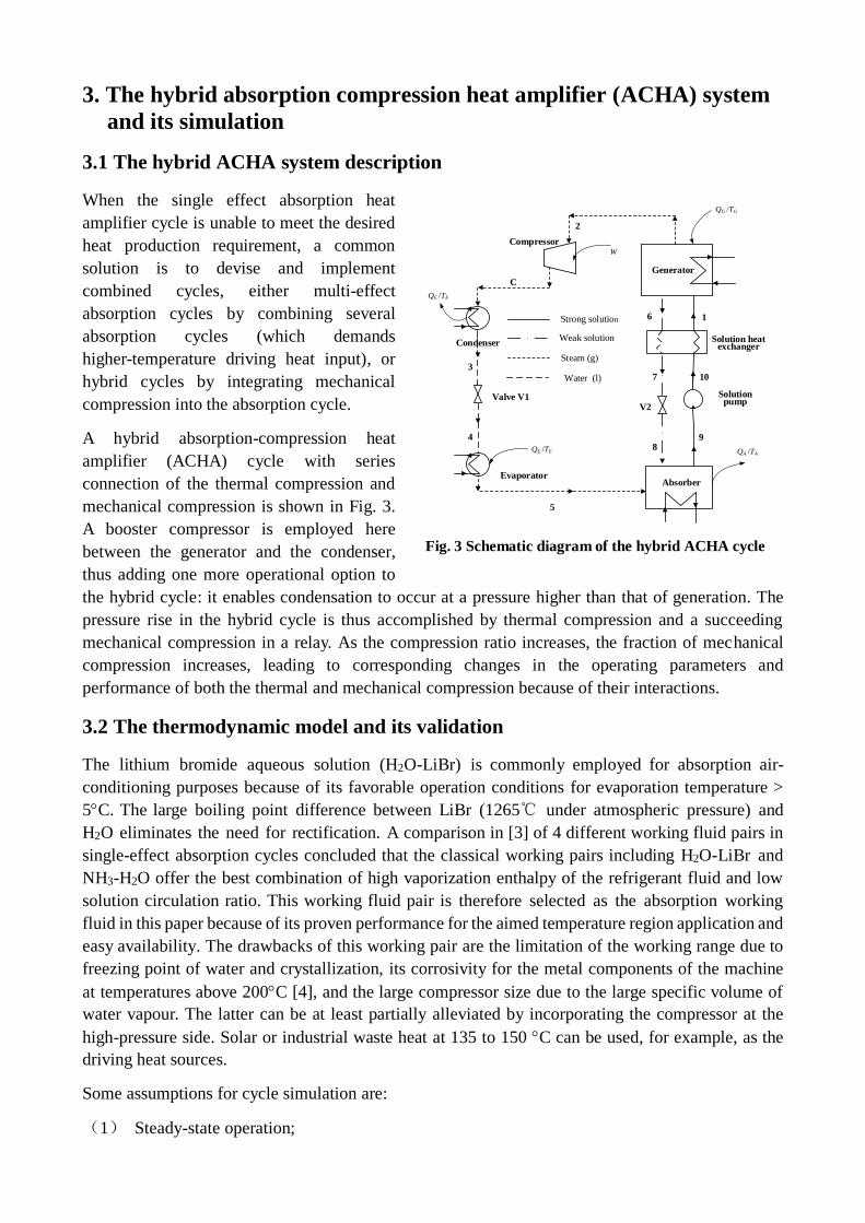
A hybrid absorption-compression heat
amplifier (ACHA) cycle with series
connection of the thermal compression and
mechanical compression is shown in Fig. 3.
A booster compressor is employed here
between the generator and the condenser,
thus adding one more operational option to
the hybrid cycle: it enables condensation to occur at a pressure higher than that of generation. The
pressure rise in the hybrid cycle is thus accomplished by thermal compression and a succeeding
mechanical compression in a relay. As the compression ratio increases, the fraction of mechanical
compression increases, leading to corresponding changes in the operating parameters and
performance of both the thermal and mechanical compression because of their interactions.
3.2 The thermodynamic model and its validation
The lithium bromide aqueous solution (H2O-LiBr) is commonly employed for absorption air-
conditioning purposes because of its favorable operation conditions for evaporation temperature >
5C. The large boiling point difference between LiBr (1265℃ under atmospheric pressure) and
H2O eliminates the need for rectification. A comparison in [3] of 4 different working fluid pairs in
single-effect absorption cycles concluded that the classical working pairs including H2O-LiBr and
NH3-H2O offer the best combination of high vaporization enthalpy of the refrigerant fluid and low
solution circulation ratio. This working fluid pair is therefore selected as the absorption working
fluid in this paper because of its proven performance for the aimed temperature region application and
easy availability. The drawbacks of this working pair are the limitation of the working range due to
freezing point of water and crystallization, its corrosivity for the metal components of the machine
at temperatures above 200C [4], and the large compressor size due to the large specific volume of
water vapour. The latter can be at least partially alleviated by incorporating the compressor at the
high-pressure side. Solar or industrial waste heat at 135 to 150 C can be used, for example, as the
driving heat sources.
Some assumptions for cycle simulation are:
(1) Steady-state operation;
1
8
7 10
6
5
4
2
Generator
Condenser
Valve V1
EvaporatorAbsorber
Solution pump
Solution heat exchanger
Strong solution
Weak solution
Steam (g)
Water (l)
3
V2
9
QG /TG
QE /TE
QA /TAQE /TE
C
CompressorW
Fig. 3 Schematic diagram of the hybrid ACHA cycle

(2) The pressure losses in the generator, condenser, evaporator and absorber are 3% of the inlet
pressure;
(3) Expansion through the throttle valve is isenthalpic;
(4) Heat losses to the ambient are ignored;
(5) The outflow solutions of the generator and absorber are at saturated states.
(6) The outlet temperatures of the absorber and condenser are set to be equal, TC = TA.
Other major equipment specifications used in the simulation are listed in Table 1.
Table 1. Specified simulation parameters of major equipment
Item Value
Minimum temperature difference in SHX, /C 5
Pump efficiency 0.7
Compressor isentropic efficiency 0.72
Mass fraction of the H2O in the refrigerant 1
The systems are simulated with the Aspen Plus process simulation software [11], in which the
component models are based on the energy balance and mass balance and species balance, with the
default relative convergence error tolerance of 0.01%, which is the specified tolerance for all tear
convergence variables. The working fluid thermal properties are calculated with the ELECNRTL for
the binary solution and the STEAM - TA for water and steam, respectively. The generator is
simulated with the “Flash/Separators” module, and the absorber with the “Mixer/Heater” module.
To validate the simulation model, the VLE (Vapor-Liquid equilibrium) data are compared with those
in [12], showing that the largest relative error is 6.93%, and that the average relative error is no more
than 2.50%.
3.3 Evaluation criteria
The coefficient of performance (COP) based on the first law of thermodynamics is defined as:
0
C A
G
Q QCOP =
Q W
(2)
This definition is for both the absorption cycle (with W being the pump power consumption) and
the hybrid cycle (with W being the sum of the pump and compressor power consumptions).
Since the two energy inputs, mechanical work W and the generator heat input QG e, are very
different in terms of their energy quality, especially when low-temperature heat or solar heat are
used as the heat source, a more proper accounting for the contribution of the low-temperature heat
input, the following heat driving coefficient of performance (COP), following [9, 10] is defined as:
C A W
G
Q Q W COPCOP
Q
(3)
Where COPW is the coefficient of performance of a vapor compression heat pump cycle operating at
the same evaporation and condensation temperatures as those of the hybrid one. The definition of
COP in Eq. (3) signifies the driving effect of low-temperature heat in the hybrid cycle, and makes it
possible to compare the performance between cycles with different configurations and parameters.

4. Discussion of System Performance and Hybridization Mechanisms
4.1 Performance of the AHA cycle
With lithium bromide aqueous solution (H2O-LiBr) as the working solution, Fig. 4 shows the
variation of the heat-driving COP, the corresponding concentration difference x and cycle
circulation ratio CR (the ratio of the strong solution mass flow rate over the refrigerant mass flow
rate) for the AHA cycle at given TE=30C and
TG=140, 145 and 150C. In Fig. 4, the ultimate heat
delivery temperature TC,u and thus ultimate
temperature lift Tu can be identified for each given
pair of TE and TG. It is found that Tu increases with
TG. When TG increases from 140C 150C for
example, Tu increases from 48C to 53 C. At the
ultimate state, the corresponding solution
concentration difference drops to 0, and the heat
amplifier has the worst performance of zero
function with COP = 1. The above observation
validates the quantitative analysis in Section 2. It is
also found that the cycle circulation ratio increases
to infinity at the ultimate state, similar to the
observation [9] that analyzes an absorption
refrigeration cycle. As the AHA cycle starts to
deviate from the ultimate state, the solution
concentration difference increase continuously, and
the circulation ratio CR first drops sharply and after
some turning point it drops very mildly. In
correspondence to the variation of CR, the cycle
COP first increase quickly and then ascends much
more gently, suggesting that the performance of the AHA cycle is mainly affected by CR and gets
deteriorated quickly at high CR.
4.2 Hybridization scheme and principle
For given high- and low-temperature heat sources
temperatures (TG and TE (PE)), and given heat
production pressure/temperature, adding a
compressor at the high pressure side allows the
generator to run under a lower pressure.
The ultimate absorption cycle for given TE and TG is
shown as the path GuCuEAGu in Fig. 5 in which
there is no heat amplification effect since x = 0 and
CR = . By introducing a compressor between the
generator and the condenser, a hybrid cycle
GiCiGuCuEAGi / GiGAiAGi is formed in which the
generation pressure drops from PG,u to PG. For
constant TG, the weak solution concentration
1.0
1.2
1.4
1.6
1.8
0.00
0.05
0.10
0.15
0.20
60 64 68 72 76 80 841
10
100
1000
10000
TE=30℃
TG=140℃
TG=145℃
TG=150℃
CO
P
TE=30℃
TG=140℃
TG=145℃
TG=150℃
x
TE=30℃
TG=140℃
TG=145℃
TG=150℃
CR
TC=T
A/℃
Fig.4 Variation of COP, x and CR
in the AHA cycle
Fig. 5 logP-T diagram of the hybrid cycle
with reduced generation temperature

decreases to xw while the strong solution concentration xs remains the same, thus leading to the
increase of the concentration difference from xu to x, and a corresponding drop of CR, where the
thermal compression becomes feasible. As the generation pressure deviates from the ultimate value,
Fig. 4 shows that the performance of the thermal compression becomes improved significantly at
first and then more mildly. The hybridization therefore enables a heat amplification effect at TC,u
without increasing the low-grade heat temperature TG. Further increase of the compression ratio
causes the generation pressure to drop to P’G, thus forming a new hybrid cycle with a higher
concentration difference, x’>x>xu. Increasing the compression ratio thus creates a series of new
hybrid cycles with continuously dropping generation pressure, increasing concentration difference,
and decreasing CR.
Theoretically, the compressor inlet pressure (which equals to PG) can be varied between given PC
and PE. Especially, when the compression ratio = 1 (PG = PC), the hybrid cycle degrades into an
absorption cycle; and when = PC/PE, (PG = PE), the hybrid cycle becomes a pure mechanical
compression one. Along with the increase of the compression ratio, the fraction of mechanical
compression increases, leading to the steady increase of the compression work, while the thermal
compression performance follows the pattern described in Fig. 4, it deviates away from the ultimate
state and exhibits changes in response to the variation of CR. Apparently, at the lower compression
ratio region, the rapid increase of the thermal compression performance overrides the steady
increase of the compression work consumption, and the hybrid cycle COP increases accordingly.
After reaching a certain pressure ratio, the gain in
the thermal compression performance becomes
more gradual so it cannot make up the rise in
compression work demand, thus causing a drop in
the hybrid cycle COP. It can thus be concluded
that there exists an optimal pressure ratio at which
a compromise is arrived between the thermal
compression and the mechanical compression, and
the hybrid cycle performance reaches the optimum
for given TE and TC. Figure 5 also shows the
influence of the generation temperature: for a
given generation pressure P’G, in correspondence
to the increase of the generation temperature from
T’G to T”G, the concentration difference increases
further from x’ to x”.
A hybrid cycle with H2O/LiBr as the working fluid
is simulated to validate the preceding results and
their discussion. Figure 6 shows the influence of
the compression ratio on the hybrid cycle
performance for the given heat delivery
temperature of TA = TC = 80C and xs = 0.376. The
generation temperature is varied between 140C
and 150C in 5C steps, the evaporation
temperatures are chosen to be 30C and 35C.
It shows the existence of an optimal compression
ratio opt for each given TG. The maximal COP
1.0 1.5 2.0 2.5
1.0
1.2
1.4
1.6
CO
P
TE=30℃
TG=140℃
TG=145℃
TG=150℃
(a)TE=30℃
1.0 1.5 2.0 2.51.30
1.35
1.40
1.45
1.50
1.55
1.60
1.65
1.70
CO
P
TE=35℃
TG=140℃
TG=145℃
TG=150℃
(b)TE=35℃
Fig.6. Influence of compression ratio in the hybrid cycle (TC= TA=80℃)

increases as TG is raised, while the corresponding opt decreases. For example, when TG is raised
from 140C to 150C, the maximal COP increase from 1.46 to 1.53, and the optimal pressure ratio
drops from 1.57 to 1.23. For the same pressure ratio, higher TG not only enhances the refrigerant
vaporization but also raises the solution concentration difference, thus favors heat generation.
Driven by the increase of both pressure ratio and TG, x increases more rapidly, and the optimal
COP is reached at a lower pressure ratio.
Comparing Figs. 6a and 6b, it is found that increase of the evaporation temperature TE has an effect
similar to that of raising TG. When TE increases from 30C to 35C, the maximal COP increases,
while the optimal pressure ratio drops. It is because when TE increases, the evaporation pressure
increases as well, leading to the reduction of the total compression requirement, thus the fraction of
mechanical compression reaches a higher level although the absolute compression ratio is still low.
5. System comparison and energy saving mechanism
5.1 System comparison
A typical hybrid ACHA cycle is simulated under the conditions of TG= 145C, TE=30C and
TC=80C with corresponding compression ratio of ε = 1.5 and compressor outlet pressure Pout =
47.4 kPa. The strong solution (in respect of the refrigerant) concentration xr = 0.376 kg/kg. Other
related assumptions are summarized in Table 1.
The parameters of the major state points in the hybrid cycle are listed in Table 2. For comparison,
an absorption heat amplifier cycle with the same working solution and a compression heat pump
cycle with H2O as working fluid are also simulated. It should be pointed out that it is very
impractical to use H2O for a compression heat pump due to the large specific volume of water vapor,
and this hypothetical cycle is simulated only for thermodynamic performance comparison. The
separate systems are assumed to operate at steady state and under the same assumption as the hybrid
cycle. The results are summarized in Table 3.
The comparison absorption heat pump has a COP of 1.29, while the CHP cycle has a much higher
performance, of COP = 4.5. As compared with the two individual systems with the same heat input
from the higher-temperature heat source and electricity input, the hybrid system produces more
mid-temperature heat, 38.1 kW as compared to 33.1 kW in the individual systems. The output
difference comes from the different heat amount taken from the low-temperature heat source. The
hybrid system takes 14.2 kW low-temperature heat at 30C and upgrades it to 80C for useful
output, which is more than double the amount in the individual AHA cycle. The low-temperature
heat contribution to the total heat input is < 22.5% in the absorption heat amplifier cycle, and > 38%
in the hybrid system, all at an energy expense of only 3% electricity input (relative to the generator
heat input).
If compared with the CHP cycle which has a much higher COP, the hybrid cycle produces more
heat for the same electricity consumption (38.1 kW vs. 3.2 kW), attributed to the contribution of the
low-temperature waste heat. Based on the data in Table 3, the electricity consumption in the hybrid
cycle is 0.73 kW to produce 38.1 kW heat at 80C. To produce the same amount of heat, the
electricity consumption in the CHP cycle will have to be increased to 8.7 kW. The mechanical work
saving ratio of the hybrid cycle is 92%. The hybrid cycle has therefore improved ability to use and
upgrade low-temperature heat as compared with either individual cycle, and achieves energy saving

with COP0 and COP higher by 10.2% and 16.6%, respectively, as compared to the sum of the two
individual systems.
Table 2. Hybrid cycle state point parameters
Stream T (℃) P (kPa) Vapor
fraction
Mass flow
rate(kg/s)
Mass fraction
LiBr H2O
1 108.5 32.1 0 1 0.642 0.358
2 145 31.6 1 0.064 0 1
C 204.2 47.4 1 0.064 0 1
3 80 46.8 0 0.064 0 1
4 30 4.2 0.086 0.064 0 1
5 29.4 4.1 1 0.064 0 1
6 145 31.6 0 0.936 0.686 0.314
7 113.5 31.4 0 0.936 0.686 0.314
8 95.3 4.2 0.018 0.936 0.686 0.314
9 80 4 0 1 0.642 0.358
10 80.1 3.21 0 1 0.642 0.358
Table 3. Performance comparison between the hybrid and individual systems
Item Hybrid Individual systems Relative increase %
AHA CHP Total* \
Input
QG kW
(145℃) 23.15 23.15 \ 23.15
\
W kW 0.73 0.73 0.73 \
QE kW
(30℃) 14.22 6.71 2.57 9.98
\
Output QC +QA kW
(80℃) 38.1 29.91 3.20 33.11
\
COP0 1.598 1.290 4.479 1.389 10.15
COP 1.507 \ \ 1.290 16.59
*The sum from the two individual systems
5.2 Analysis of energy saving mechanism
Increasing the temperature lift T causes the COP to drop for both individual absorption and vapour
compression heat pump cycles in their different patterns. The vapour compression cycle has a much
higher performance, but its COP also drops more quickly with the increase of the compression ratio.
In contrast, the COP of the absorption cycle exhibits a relatively mild variation, except the dramatic
change near its ultimate state. When integrated into a hybrid cycle, an interrelationship between
them has been established: as the compressor compression ratio increases, the fraction of the
mechanical compression increases while that of the thermal compression drops, leading to the
continuous evolution of the parameters and performance of both sub-cycles and their interrelation.
Based on the understanding of the performance of the absorption heat amplifier and the vapour
compression heat pump, the energy saving mechanism is discussed with the help of log P-h diagram
(Fig. 7). The parameters of each state point are from the simulation results described in Section 5.1.
The AHA cycle is also included for comparison, for the same evaporation (30C/4.2 kPa) and

condensation (80C/46.8 kPa) parameters values.
Fig.7 describes the diagrams of log p-T of the hybrid (solid line) and absorption heat amplifier AHA
cycle (dotted line). The two cycles share the same parameters for the condensation and evaporation
processes (represented by path 4-5-6), and the same strong solution concentration and mass flow
rate. Main differences exist for the absorption (paths 5/8-9 for hybrid vs. 5/8a-9 for AHA) and
generation processes (paths 1-2/6 for hybrid and 1a-2a/6a for AHA) due to additional pressure level
of 31.6 kPa for the generation process in the hybrid cycle. Therefore in the hybrid cycle, the
compression pressure elevation from PE to PC is accomplished by a cascade of the thermal
compression (path 9-1) and mechanical compression (path 2-C), as compared with the thermal
compression alone (path 8a-1a) in the AHA cycle. From the left to the right, there are 3 phase
equilibrium lines with decreasing refrigerant mass concentration (xr, xs and xw, respectively), and
they are 1.0, 0.358, and 0.315, for the hybrid cycle; and 1.0, 0.358 and 0.344 for the AHA cycle.
The xw line for the hybrid cycle is on the right of that for the AHA cycle, i.e., xw is lower for the
hybrid cycle, despite the same generation temperature of 145C in both cycles (T2 = T2a). For the
same strong solution concentration, lower xw indicates more refrigerant is vaporized in the
generation process, leading to more heat obtained from the evaporator and more heat delivery.
As mentioned, there exists an internal restriction between the heat production and its temperature
lift T in the absorption heat amplifier cycle. Higher temperature lift lowers the heat production. By
sharing the compression with a mechanical
process, the temperature lift of the thermal
compression drops as the compressor
compression ratio increases, thus it has
higher heat production than that in the pure
AHA cycle, and the increment comes from
the lower-temperature heat source via the
evaporation process. At the same time, the
performance of the mechanical compression
drops but very importantly is still within the
high COP region. This explains how a small
fraction of mechanical compression helps
improve the thermal compression
performance. The core is the balance of the
gain from the absorption side and the
performance deterioration in the mechanical
side, and thus the objective is to maximize the enhancement of low-temperature heat absorption for
the least input of mechanical work, by cascade use of the two energy inputs. It is concluded that the
hybrid cycle enhances the low-temperature thermal compression performance to a level which can’t
be achieved by an individual absorption heat pump cycle.
6. Conclusions
The absorption-compression hybrid cycle of heat-amplifier type was studied, focused on a
hybridization principle based on the interrelation between the two sub-cycles, and the resulting
energy saving mechanisms were analyzed. The theoretical analysis was validated by a simulation of
a hybrid cycle working with H2O/LiBr solution.
The compression in the hybrid cycle can be regarded as a combination of mechanical compression
20 40 60 80 100 120 140 160 180 200 2200.4
0.6
0.8
1.0
1.2
1.4
1.6
1.8
8a
2a,6a1a
4kPa
32kPa
48kPa
4
58
9
C
2,61
3
T/℃
logp
(p
/kP
a)
hybrid cycle
absorption cycle
Fig.7 Hybrid and absorption heat pump cycle
comparison

and thermal compression. The interrelation between the two sub-cycles determines the hybrid cycle
performance and the existence of an optimal compressor compression ratio of 1.2~1.8.
To explore the thermodynamic performance and the energy saving mechanism of the hybrid system, a
comparison was also conducted with a conventional absorption heat amplifier and a vapor
compression heat pump cycle working within the same temperature regions. With the help of a small
fraction of mechanical work (<5% to the waste heat input to the generator), the hybrid cycle accepts
much more heat from the lower-temperature heat source than does the absorption heat amplifier
cycle, and upgrades it to useful output. If compared with the vapor compression cycle which has a
much higher COP, the hybrid cycle produces more heat for the same electricity consumption,
attributed to the contribution of the low-temperature waste heat. The mechanical work saving ratio
reaches up to 92%. The hybrid cycle has therefore improved ability to use and upgrade
low-temperature heat, and achieves energy saving exhibited by COP0 and COP higher by 10.2%
and 16.6%, respectively, as compared to the sum of the two individual systems.
It was concluded that the hybrid cycle achieves significant energy saving of high-quality
mechanical work, and also improves the low-temperature thermal compression performance to a
level which can’t be achieved in an individual absorption heat pump cycle, i.e, it achieves
simultaneously the better use of low-grade waste heat and energy saving of mechanical work, both
attributed to the thermodynamically efficient cascade use to two energy inputs.
Acknowledgments
The authors gratefully acknowledge support of the National Key Fundamental Research Project of
China (No. 2013CB228302;No.2014CB249202)
Nomenclature
ACHA Hybrid absorption-compression heat amplifier cycle
AHA Absorption heat amplifier cycle
CHP Compression heat pump
COP Coefficient of performance, dimensionless
CR Cycle circulation ratio, dimensionless
m Mass flow rate, kg/s
P Pressure, kPa
Q Heat duty, kW
T Temperature,℃
W Power consumption, kW
x Solution concentration, kg/kg
Δx Solution concentration difference, kg/kg
Greek symbols
ε Compressor pressure ratio, dimensionless
Subscripts
A Absorber
C Condenser
E Evaporator G Generator
opt Optimal value
r Refrigerant
s Strong solution

u Ultimate state
w Weak solution
References
[1]Y. Fan, L. Luo, B. Souyri, Review of solar sorption refrigeration technologies: development and
applications, Renewable & Sustainable Energy Reviews, 2007,11: 1758-1775.
[2]R. Ventas, A. Lecuona, A. Zacarias, M. Venegas, Ammonia-Lithium nitrate absorption chiller
with an integrated low-pressure compression booster cycle for low driving temperature, Applied
Thermal Engineering, 2010, 30: 1351-1359.
[3]D. Boer, M. Valles and A. Coronas, Performance of double effect absorption compression cycles
for air-conditioning using methanol-TEGDME and TFE-TEGDME systems as working pairs, Int.
J. Refrig., 1998, 21(7): 542-555.
[4]Jin-Soo Kim, Felix Ziegler, Huen Lee, Simulation of the compression-assisted triple-effect
H2O/LiBr absorption cooling cycles, Applied Thermal Engineering, 2002,22:295-308.
[5]Norio Sawada, Kazuaki Minato, Yoshifumi Kunigi, Teiichi Mochizuki, Takao Kashiwagi, Cycle
simulation and COP evaluation of absorption-compression hybrid heat pumps: heat amplifier
type, International Absorption Heat Pump Conference ASME, 1993, 31:471-476.
[6]Daliang Hong, Limin Tang, Yijian He, Guangming Chen, A novel absorption refrigeration cycle,
Applied Thermal Engineering, 2010, 30: 2045-2050.
[7]Guangming Chen, Eiji Hihara, A new absorption refrigeration cycle solar energy, Solar Energy,
1999, 66(6): 479-482.
[8]Wei Han, Liuli Sun, Danxing Zheng, Hongguang Jin, Sijun Ma, Xuye Jing, New hybrid
absorption-compression refrigeration system based on cascade use of mid-temperature waste
heat, Applied Energy, 2013, 106: 383-390.
[9]Danxing Zheng, Xuelin Meng, Ultimate refrigerating conditions, behavior turning and a
thermodynamic analysis for absorption-compression hybrid refrigeration cycle, Energy
Conversion and Management, 2012, 56: 166-174.
[10]Xuelin Meng, Danxing Zheng, Jianzhao Wang, Xinru Li, Energy saving mechanism analysis of
the absorption-compression hybrid refrigeration cycle, Renewable Energy,2013, 57: 43-50.
[11]Aspen Plus. Aspen Technology, Inc., version 7.3. See also: http://www.aspentech.com/.
[12]J. Patek, J. Klomfar A computationally effective formulation of the thermodynamics properties
of LiBr–H2O solutions from 273 to 500 K over full composition range Int. J. Refrig., 29 (2006),
pp. 566–578.