Embed Size (px)
Citation preview

2
ILC RDR baseline schematic

Parameters:
• Optimize the positron yields for known technologies: – Superconducting helical undulator.
• Undulator parameter: K=0.92, u=1.15cm
– Capturing magnets • Optical matching device: FC and ¼ wave transformer
– Targets: 0.4 X0 Ti, W and liquid Pb also considered (not covered in this talk).
• Damping ring acceptance– Energy spread < 1%– emittance_x+emittance_y < 0.09 m-rad
• Goal:– Achieve yield of 1.5 positrons per electron in the drive beam.
• No polarization required.• Polarization required.

Status of the critical hardware components
• 4 meter cryo-module, two 1.7m long RDR undulator. (Completed, STFC/RAL/Daresbury)
• Target wheel prototype design and test. (Lancaster/Cockcroft/STFC/LLNL)• Rotating vacuum seal prototype test. (LLNL, ongoing)• Capturing RF structure. (SLAC, Completed)• Flux Concentrator prototype design. (LLNL, ongoing)• New short period, high K undulator. (Cockcroft/STFC, ongoing).

EuCard Meeting, 7-4, University of
Geneva, 8/9 June5
7th Positron Source Collaboration Meeting, DESY
4 metre Cryomodule• Two 1.7 metre helical undulator
magnets have been successfully made using NbTi.
• Magnets positioned back to back in cryostat.

Target Prototype Design and Testing (Ian Bailey, Lancaster/Cockcroft/STFC/LLNL):1 meter diameter; 2000 rpm,Work Completed.
Torque transducer
15kW motor
Dipole magnet
mwheel~18kg
Accelerometers
ILC Real target:
Wheel diameter: 2m
Spinning Speed ~ 900 rpm
Thickness: 1.4 cm

Target Prototype at LLNLPrototype II - Rotating vacuum seal test
• Current design has rotating ferrofluidic vacuum seals
• Cooling water flows along the shaft
• Test leakage of vaccum/fluids from:– Vibration
– Magnetic field effects
11/11/2010 Global Design Effort 7

Vacuum seal test
Altered layout after discussions with Rigaku Single-shaft design, larger bore Hollow shaft motor Rigaku has used previously Water union may not be in this test configuration
Daresbury prototype wheel does not have cooling channels Water in shaft only
11/11/2010 Global Design Effort 8
Water Union
Drive Motor
Support Bearing
Rotating Ferrofluidic
Vacuum Seal
Cooling water
connection

Vacuum seal test
• Rotordynamics analysis and design for cantilevered layout– Changed layout from Daresbury test– Requires re-evaluation of vibration modes due
to new components and configuration
• Diagnostics setup (pressure sensors, filter and witness plate chemical analysis, mechanical behavior)
• Developing drawings• Acquire LLNL ES & H approval for operating
plan
11/11/2010 Global Design Effort 9

From Juwen Wang/SLAC
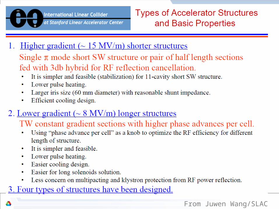
Prototyping a SW cavity for ILC e+ source.
• Fabricated and conditioned at SLAC, achieved 13.8 MV/m with breakdown of 1/hr.• Figures from Juwen Wang and Faya Wang

ILC Positron source optimization: Cases Studied:
• Common Input Parameters:– Undulator parameter: K=0.92, u=1.15cm– Target: 0.4 X0 Ti– Drift between undulator and target: 400m– Photon collimator: None
• OMD:– Flux Concentrator Capturing (137 m long Undulator).– Quarter Wave Transformer Capturing (231 m long undulator).
• Undulator Impacts on Drive Beam– Energy Spread and, – Emittance
• Target Energy Deposition.• Path toward higher polarizations
– Photon collimators

A pulsed flux concentrator
• Pulsing the exterior coil enhances the magnetic field in the center.– Needs ~ 1ms pulse width flattop– Similar device built 40 years ago.
Cryogenic nitrogen cooling of the concentrator plates.

Yield Calculations Using RDR Undulator Parameters (137 meter and FC without photon collimators )
Drive beam energy
Yield Polarization
Required Undulator Length for 1.5 Yield
Emittance Growth X/Y for 1.5 Yield*
Energy Spread from Undulator for 1.5
Yield
50 GeV 0.0033 0.42 Very long
100 GeV 0.2911 0.39 685 m
150 GeV 1.531 0.34 137 m ~ -2.5%/-1.6% 0.17%
200 GeV 3.336 0.27 61 m
250 GeV 5.053 0.23 40 m ~-1%/-0.4% 0.18%
* No Quads misalignment included.

Emittance growth due to BPM to Quad misalignments-- From Jim Clark’s report
17
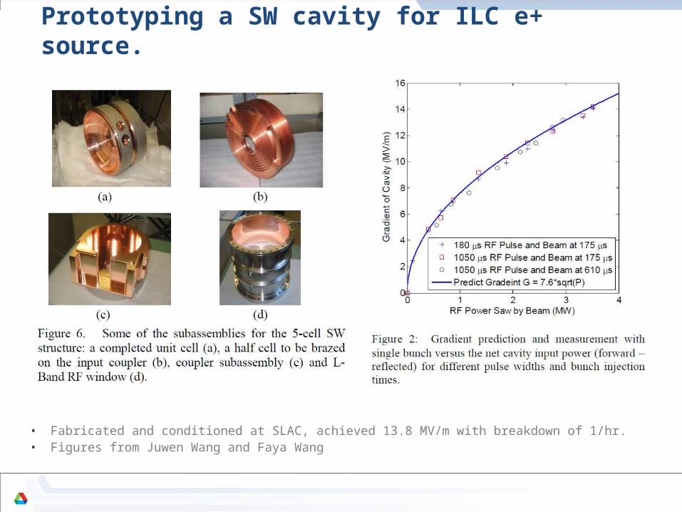
RDR undulator, Quarter Wave Capturing Magnet (SB2009)
• Undulator: RDR undulator, K=0.92, u=1.15cm• Length of undulator: 231m• Target to end of undulator:400m• Target: 0.4X0, Ti• Drive beam energies: 50GeV to 250GeV (SB2009)• Reference: 150 GeV

18
¼ wave solenoid
• Low field, 1 Tesla on axis, tapers down to 1/2 T.
• Capture efficiency is only 25% less than flux concentrator
• Low field at the target reduces eddy currents
• This is probably easier to engineer than flux concentrator
• SC, NC or pulsed NC?
ANL ¼ wave solenoid simulations
W. LiuThe target will be rotating in a B field of about 0.2T

19
Yield and polarization of RDR configuration for different drive beam energy (for SB2009)
Drive beam energy
Yield Polarization
50GeV 0.0041 0.403
100GeV 0.3138 0.373
150GeV 1.572 0.314
200GeV 3.298 0.265
250GeV 4.898 0.221
Drive beam energy
Energy lost per 100m
Energy lost for 1.5 yield
50GeV ~225MeV N/A
100GeV ~900MeV ~9.9GeV
150GeV ~2GeV ~4.6GeV
200GeV ~3.6GeV ~3.7GeV
250GeV ~5.6GeV ~3.96GeV

20
OMD comparison• Same target • Beam and accelerator phase optimized for each OMD• OMD compared:
– AMD– Flux concentrator– ¼ wave transformer– Lithium lens
OMD Capture efficiency
Immersed target, AMD
(6T-0.5T in 20 cm)
~30%
Non-immersed target, flux concentrator
(0-3.5T in 2cm, 3.5T-0.5T 14cm)
~26%
1/4 wave transformer
(1T, 2cm)
~15%
0.5T Back ground solenoid only ~10%
Lithium lens ~29%

Energy deposition/accumulation on Target with RDR undulator
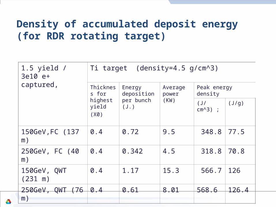
Density of accumulated deposit energy (for RDR rotating target)
1.5 yield / 3e10 e+ captured,
Ti target (density=4.5 g/cm^3)
Thickness for highest yield (X0)
Energy deposition per bunch (J.)
Average power (KW)
Peak energy density
(J/cm^3) ; (J/g)
150GeV,FC (137 m) 0.4 0.72 9.5 348.8 77.5
250GeV, FC (40 m) 0.4 0.342 4.5 318.8 70.8
150GeV, QWT (231 m) 0.4 1.17 15.3 566.7 126
250GeV, QWT (76 m) 0.4 0.61 8.01 568.6 126.4

Shockwaves in the target• Energy deposition causes shockwaves
in the material– If shock exceeds strain limit of material
chunks can spall from the face• The SLC target showed spall damage
after radiation damage had weakened the target material.
• Initial calculations from LLNL had shown no problem in Titanium target
• Two groups are trying to reconfirm result– FlexPDE (S. Hesselbach, Durham
DESY)– ANSYS (L. Fernandez-Hernando,
Daresbury)– No definative results yet
• Investigating possible shockwave experiments– FLASH(?)– https://znwiki3.ifh.de/LCpositrons/
TargetShockWaveStudy
SLC positron target after decommissioning
S. Hesselbach, Durham
11/11/2010 JGronberg, LLNL
Global Design Effort 23

High K and short period Undulator Option
• Important to SB2009 scenarios.• Assumptions:
– Length of undulator: 231m– Drive beam energy: 100GeV– Target: 0.4X0, Ti– Photon Collimation: None– Drift to target: 400m from end of undulator– OMD:FC, 14cm long, ramping up from 0.5T to over 3T in 2cm and decrease adiabatically
down to 0.5T in 12cm.
• Probably aperture will be relative small (no number yet). Impact to the drive beam to be studied.
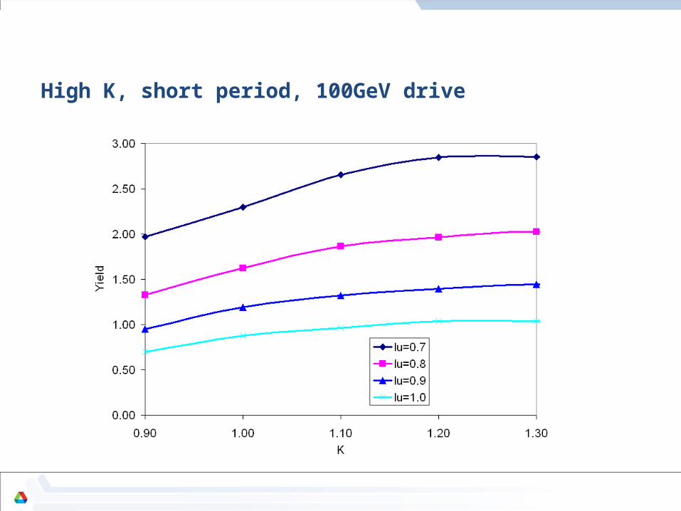
High K, short period, 100GeV drive

Towards High Polarizations

• Most sensitive parameter: Transverse photon distribution:– Photon Collimation would eliminate unwanted off axis photons that
have low polarization.– Other parameters (drive beam energy and low K undulator) also have
influences, but not dominate (skipped from this presentation).

28
Drive beam energy
Energy lost per 100m
Energy lost for 1.5 yield and 60% polarization
150GeV ~2GeV ~8.8GeV
231m RDR undulator, 150GeV drive beam, ¼ wave transformer
Polarization upgrade
With QWT, with a photon collimator to upgrade the polarization to 60%, the positron yield will drop to ~0.8

Yield with 60% Pol. As function of drive beam energy. 231m long RDR undulator
• Yield of 1.5 with 60% yield can be reached with drive beam energy of ~162GeV
Flux concentrator is used as OMD

30
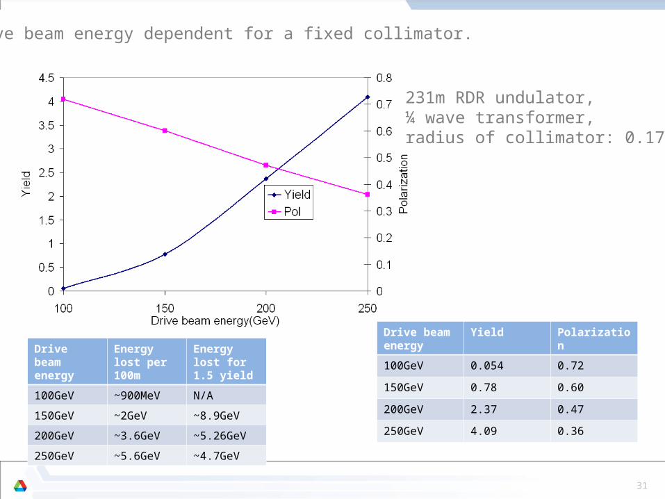
Polarization dependents on Collimator for 250GeV drive beam energy
Drive beam energy
Energy lost per 100m
Energy lost for 1.5 yield and 60% polarization
250GeV ~5.6GeV ~13.8GeV
231 RDR undulator driving with 250GeV beamOMD is QWT. Target is 0.4X0 Ti
31
Drive beam energy
Yield Polarization
100GeV 0.054 0.72
150GeV 0.78 0.60
200GeV 2.37 0.47
250GeV 4.09 0.36
Drive beam energy
Energy lost per 100m
Energy lost for 1.5 yield
100GeV ~900MeV N/A
150GeV ~2GeV ~8.9GeV
200GeV ~3.6GeV ~5.26GeV
250GeV ~5.6GeV ~4.7GeV
Drive beam energy dependent for a fixed collimator.
231m RDR undulator,¼ wave transformer,radius of collimator: 0.17cm

Drive beam energy 150GeV, K=0.9,u=0.9, 231 meter undulator and Flux concentrator
For 150GeV drive beam, 60% polarization required a photon collimator with an iris of ~1.6mm in radius. The corresponding yield is ~2 for 231m long undulator

Yield with 60% Pol. As function of drive beam energy
• With 231m long undulator with K=0.9, u=0.9, 1.5 yield with 60% polarization can be achieved with drive beam energy of about 132GeV
Flux concentrator is used as OMD

R/Ds of Alternative
Solutions(from Omori-san)

R/Ds are on going for Alternative Solutions as well• Why Alternative Solutions?
• Pursuit better/advanced solutions • Mitigate Risks
• Back Up
• Alternative Solutions• Compton (French-CERN-Japanese Collab.)
• Conventional• only e+ source which we have experience in real accelerators
• Independent Source with Polarization(1) French 4-Mirror Cavity installed in ATF: F-J Collab.(2) Multi-bunch observation with 2-Mirror Cavity
(3) Liquid Target : Russian-Japanese Collab. (4) Hybrid Target : French-CERN-Japanese Collab. (5) Truly Conventional (Slow Rotation Target: 4m/s)
• 300 Hz scheme (expansion in time) to mitigate target issue
note: In following each slide, (1), (2), (3), (4), (5), progress in recent 6 months is described.
“ILC-CLIC e+ generation” group works also for the alternative schemes.

Compton R/Ds
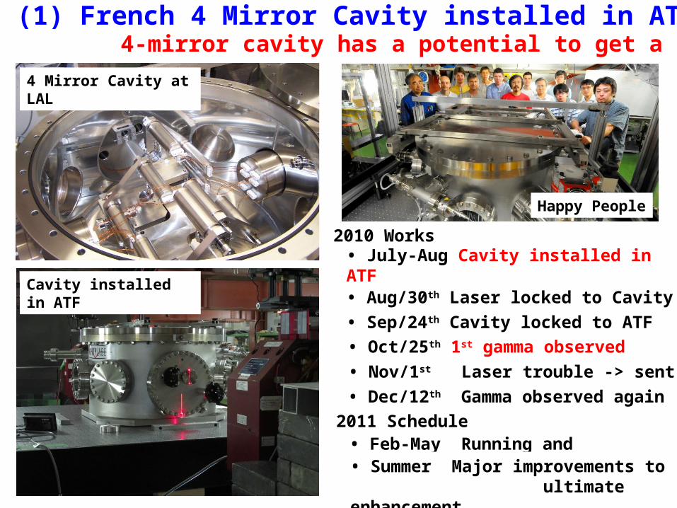
(1) French 4 Mirror Cavity installed in ATF: 4-mirror cavity has a potential to get a smaller spot4 Mirror Cavity at LAL
Cavity installed in ATF
• July-Aug Cavity installed in ATF French Team (9 persons) at KEK • Aug/30th Laser locked to Cavity
• Sep/24th Cavity locked to ATF • Oct/25th 1st gamma observed
2010 Works
2011 Schedule
• Nov/1st Laser trouble -> sent to Zurich • Dec/12th Gamma observed again
• Feb-May Running and improvements
Happy People
• Summer Major improvements to ultimate enhancement

(2) Multi-bunch -ray measurement with 2-M Cavity: aiming to check bunch-by-bunch uniformity
Time (n sec)
<- Bunch-by-bunch data of number of -rays. Each peak corresponds each bunch. (10 bunches/train) A new -ray detector was installed to measure bunch-by- bunch-ray data.
Bunch number vs number of -rays. ->
Bunch-by-bunch number of -rays were observed to be approx. uniform
Conventional R/Ds

(3) Hybrid Target : get data and compare with simulation
We took systematic data.– Hybrid target
– 1-mm thick tungsten single crystal– amorphous tungsten plate with various thicknesses
– Conventional target (for comparison)– with various thicknesses
– impinging 8-GeV electron beams – e+ momentum 5, 10, 20 MeV/c– temperature
• at equilibrium • single bunch temp. rise
– beam profile
oscillation is due to AC power noise (50Hz at KEK)
e- e+, e-,
e-
e+
Time (m sec)
Hybrid target test was performed at KEK linac.
Tem
p. (
deg
. C)
single bunch temperature rise
• Hybrid: The systematic data allows us to test the simulation.• Conventional: the data is also useful to evaluate conventional target. • We seek a possibility for both hybrid and conventional.
note: the idea of hybrid target is resulting from long-term investigations with experiments in CERN (Franco-Russian collab.)

No damage, defect, or crack was observed.
(4) Liquid Target : destructive test of the BN window
Sample S:3 (charge=2)
2 spots (reduced brilliance) were observed by eyes. We can see them in photo.
2 spots (reduced brilliance) were observed by eyes. We can see them in photo.
W radiator (acting Liq. lead)
BN window
BN window test of liquid target was performed at KEKB 8 GeV ring. charge =2:
2 x "instantaneous E deposit" (by 132 bunches) of 300 Hz scheme (2x96J/g)

e- directly on to Tungsten=4.0mm
(5) Truly Conventional (Slow Rotation Target 4 m/s):
Both an analytic estimation (*) and a simulation ( by PPS-SIM developed by DESY) shows that there is no show stopper in the truly conventional solution.
: PEDD J/g
: Total deposit kW
colored band:accepted e+/e-
: dT/triplet (132 bunch)
Parameter Plots for 300 Hz scheme
Ttarget (mm)
Ebeam (GeV)
explore "Ttarget – Ebaem" space to seek a solution
colored band
Def: Truly conventional solution :no hybrid target, no liquid target, we only assume tungsten target with slow rotation (single target).
(*) analytic estimation based on the formula of CLIC‐note 465 (T. Kamitani & L. Rinolfi)

Summary
– Systematic parameters scans studied for the RDR undulator using Quarter Wave and Flux concentrator
• Flux concentrator scheme (under-development) uses undulator length to 137 m. A conservative scheme that uses quarter wave magnet (no development required) uses 231 m.
• Also FC reduces the target energy deposition load when compared with quarter wave.
• Impact on the drive beam parameters from undulator investigated and no major effect observed for both schemes.
• Target energy deposition issues explored. For the required yield, power and peak energy depositions calculated. Further investigations are needed for the target damage thresholds.
• Polarization issues are investigated, and it is a complex process and key is the collimation technology development
– For SB2009, which has low energy option, a new undulator might simplify the schemes proposed (10 Hz operation).
– Alternative technologies are being investigated as backup plans.