Embed Size (px)
Citation preview
Performance STOL, LLC. Manual No. PSTOL-013
1 Manual Revision A June 1, 2017
THIS MANUAL INCLUDES INFORMATION PROPRIETY TO PERFORMANCE STOL, LLC. AND SHALL NOT BE USED TO MANUFACTURE OR REPRODUCE ANY PART OR ASSEMBLY WITHOUT THE PRIOR WRITTEN PERMISSION OF PERFORMANCE STOL, LLC.
performance
S T O L
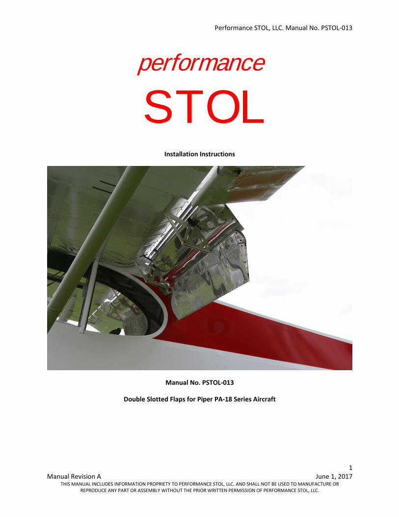
Installation Instructions
Manual No. PSTOL-013
Double Slotted Flaps for Piper PA-18 Series Aircraft
Performance STOL, LLC. Manual No. PSTOL-013
2 Manual Revision A June 1, 2017
THIS MANUAL INCLUDES INFORMATION PROPRIETY TO PERFORMANCE STOL, LLC. AND SHALL NOT BE USED TO MANUFACTURE OR REPRODUCE ANY PART OR ASSEMBLY WITHOUT THE PRIOR WRITTEN PERMISSION OF PERFORMANCE STOL, LLC.
This Page Intentionally Left Blank
Performance STOL, LLC. Manual No. PSTOL-013
3 Manual Revision A June 1, 2017
THIS MANUAL INCLUDES INFORMATION PROPRIETY TO PERFORMANCE STOL, LLC. AND SHALL NOT BE USED TO MANUFACTURE OR REPRODUCE ANY PART OR ASSEMBLY WITHOUT THE PRIOR WRITTEN PERMISSION OF PERFORMANCE STOL, LLC.
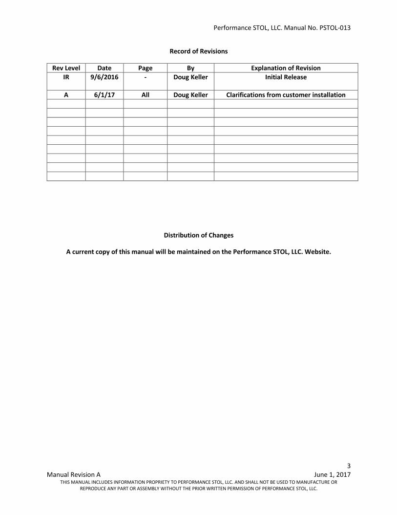
Record of Revisions
Rev Level Date Page By Explanation of Revision IR 9/6/2016
- Doug Keller Initial Release
A 6/1/17 All Doug Keller Clarifications from customer installation
Distribution of Changes
A current copy of this manual will be maintained on the Performance STOL, LLC. Website.
Performance STOL, LLC. Manual No. PSTOL-013
4 Manual Revision A June 1, 2017
THIS MANUAL INCLUDES INFORMATION PROPRIETY TO PERFORMANCE STOL, LLC. AND SHALL NOT BE USED TO MANUFACTURE OR REPRODUCE ANY PART OR ASSEMBLY WITHOUT THE PRIOR WRITTEN PERMISSION OF PERFORMANCE STOL, LLC.
Contents
Introduction and Description ............................................................................................................ 5
Placards and Marking ........................................................................................................................ 5
Installation Instructions .................................................................................................................... 6
Weight and Balance ........................................................................................................................ 23
Trouble Shooting ............................................................................................................................. 23
Drawings and Diagrams .................................................................................................................. 24
Engineering Changes and Amendments ......................................................................................... 24
Figure 1: Four rivets to drill out in inboard flap false spar ........................................................................... 7 Figure 2: Four rivets to drill out in outboard flap false spar ......................................................................... 8 Figure 3: Inboard False Spar Doubler Position .............................................................................................. 8 Figure 4: Outboard False Spar Doubler Position ........................................................................................... 9 Figure 5: Match drilling existing rivet holes in inboard doubler from template .......................................... 9 Figure 6: Rivet doublers to false spar ......................................................................................................... 10 Figure 7: Rib Flange Doubler Location ........................................................................................................ 11 Figure 8: Rib Flange Doubler Installation Detail ......................................................................................... 11 Figure 9: Rib Flange Doubler Installation Photo ......................................................................................... 12 Figure 10: Install flap hangar extender and cleco both aft holes ............................................................... 13 Figure 11: Insert flap channel stiffener into flap hangar ............................................................................ 14 Figure 12: Extender and stiffener bolted to flap hanger ............................................................................ 14 Figure 13: Flap Hanger Extender installed .................................................................................................. 15 Figure 15: Inboard Vane hanger installed on flap hanger extender ........................................................... 16 Figure 16: Vane push rod installed ............................................................................................................. 17 Figure 17: Flap Element installed ................................................................................................................ 18 Figure 18: Mount turnbuckle assemblies ................................................................................................... 19 Figure 19: Maximum Flap Deployment Angles ........................................................................................... 20 Figure 20: Install Gap Seals ......................................................................................................................... 20 Figure 21: Upper wing root fairing modification ........................................................................................ 21 Figure 22: Lower wing root fairing modification ........................................................................................ 22
Performance STOL, LLC. Manual No. PSTOL-013
5 Manual Revision A June 1, 2017
THIS MANUAL INCLUDES INFORMATION PROPRIETY TO PERFORMANCE STOL, LLC. AND SHALL NOT BE USED TO MANUFACTURE OR REPRODUCE ANY PART OR ASSEMBLY WITHOUT THE PRIOR WRITTEN PERMISSION OF PERFORMANCE STOL, LLC.
Introduction and Description
Introduction:
The performance STOL PA-18 Double Slotted Flap system is a replacement flap system with enhanced performance over the original PA-18 flap system.
Description:
The Performance STOL PA-18 Double Slotted flap system is composed of three key components:
1. New flap hinges which replace the original flap hinges. The installer simply drills out the original flap hinges and installs the Performance STOL flap hinges, along with a flap hanger stiffener and inboard and outboard false spar doublers.
2. A vane element, the first of the two flap elements, mounts directly to the newly installed flap hinges. A new push rod is provided to connect the vane element to the existing original flap bell crank inside the wing.
3. The flap element, the second of the two element flap system, mounts directly onto the vane element. A new push rod (called “link turnbuckle assembly”), is provided to control the flap element and is attached to the new flap hinge.
Instructions for installation of this kit are detailed within this manual.
Placards and Marking
The following information must be displayed in the form of a placard in addition to those specified in the operator’s basic handbook.
DO NOT EXCEED 70 MPH IAS WITH FULL FLAPS DEPLOYED
This placard is placed on the instrument panel immediately adjacent to the airspeed indicator and in full view of pilot as part of the installation instructions.
Performance STOL, LLC. Manual No. PSTOL-013
6 Manual Revision A June 1, 2017
THIS MANUAL INCLUDES INFORMATION PROPRIETY TO PERFORMANCE STOL, LLC. AND SHALL NOT BE USED TO MANUFACTURE OR REPRODUCE ANY PART OR ASSEMBLY WITHOUT THE PRIOR WRITTEN PERMISSION OF PERFORMANCE STOL, LLC.
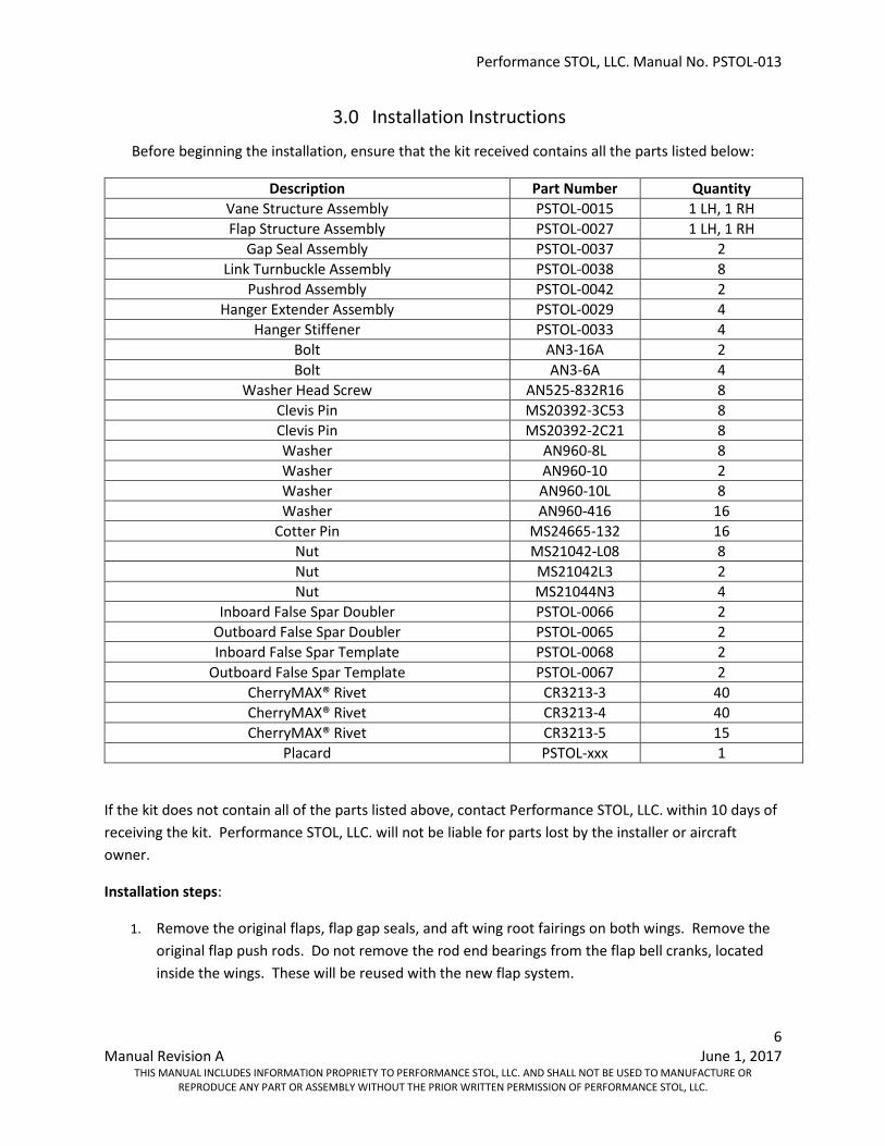
Installation Instructions
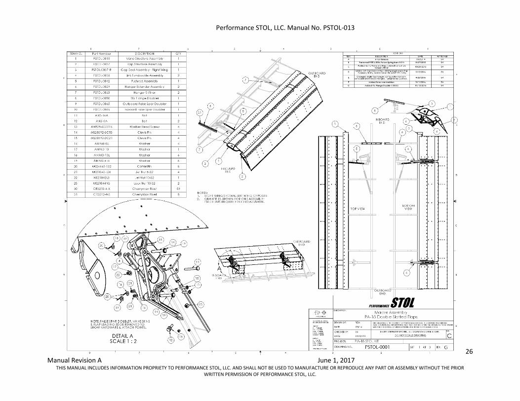
Before beginning the installation, ensure that the kit received contains all the parts listed below:
Description Part Number Quantity Vane Structure Assembly PSTOL-0015 1 LH, 1 RH Flap Structure Assembly PSTOL-0027 1 LH, 1 RH
Gap Seal Assembly PSTOL-0037 2 Link Turnbuckle Assembly PSTOL-0038 8
Pushrod Assembly PSTOL-0042 2 Hanger Extender Assembly PSTOL-0029 4
Hanger Stiffener PSTOL-0033 4 Bolt AN3-16A 2 Bolt AN3-6A 4
Washer Head Screw AN525-832R16 8 Clevis Pin MS20392-3C53 8 Clevis Pin MS20392-2C21 8 Washer AN960-8L 8 Washer AN960-10 2 Washer AN960-10L 8 Washer AN960-416 16
Cotter Pin MS24665-132 16 Nut MS21042-L08 8 Nut MS21042L3 2 Nut MS21044N3 4
Inboard False Spar Doubler PSTOL-0066 2 Outboard False Spar Doubler PSTOL-0065 2 Inboard False Spar Template PSTOL-0068 2
Outboard False Spar Template PSTOL-0067 2 CherryMAX® Rivet CR3213-3 40 CherryMAX® Rivet CR3213-4 40 CherryMAX® Rivet CR3213-5 15
Placard PSTOL-xxx 1
If the kit does not contain all of the parts listed above, contact Performance STOL, LLC. within 10 days of receiving the kit. Performance STOL, LLC. will not be liable for parts lost by the installer or aircraft owner.
Installation steps:
1. Remove the original flaps, flap gap seals, and aft wing root fairings on both wings. Remove the original flap push rods. Do not remove the rod end bearings from the flap bell cranks, located inside the wings. These will be reused with the new flap system.
Performance STOL, LLC. Manual No. PSTOL-013
7 Manual Revision A June 1, 2017
THIS MANUAL INCLUDES INFORMATION PROPRIETY TO PERFORMANCE STOL, LLC. AND SHALL NOT BE USED TO MANUFACTURE OR REPRODUCE ANY PART OR ASSEMBLY WITHOUT THE PRIOR WRITTEN PERMISSION OF PERFORMANCE STOL, LLC.
2. Drill out the original aluminum flap hinge block rivets from the flap hangers (two rivets per hanger). Use caution when drilling so as to not create oblong rivet holes. The rivets are steel. A #40 drill bit is recommended. Drill through the rivet head and opposing shop head only far enough to get through the flap hanger. Use a #30 drill bit to remove the rivet head and opposing shop head. Use pliers to grip the flap hinge block and pry it out of the flap hanger.
3. Clean the area where the flap hinges were located with a wire brush, if necessary, to remove
any surface corrosion. The flap hangers are steel and will corrode if not painted.
Note: If aircraft has Dakota Cub wings, remove the cross screw that passes through the flap hanger channel, inside the wing.
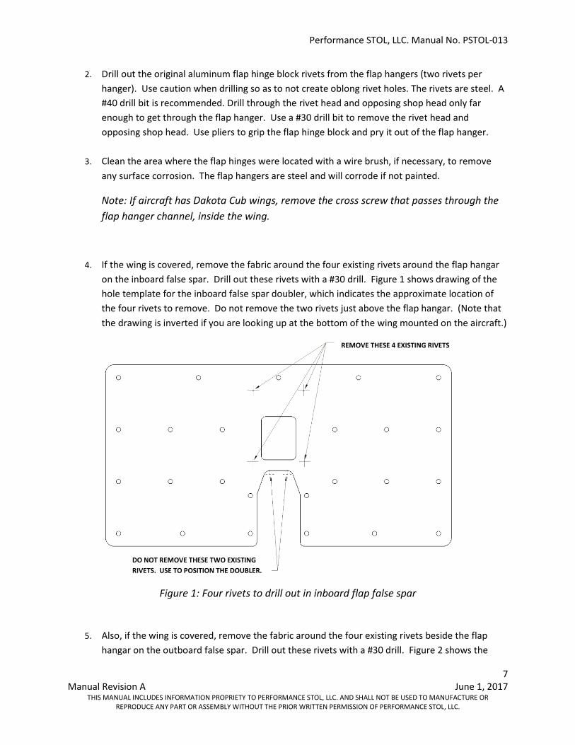
4. If the wing is covered, remove the fabric around the four existing rivets around the flap hangar on the inboard false spar. Drill out these rivets with a #30 drill. Figure 1 shows drawing of the hole template for the inboard false spar doubler, which indicates the approximate location of the four rivets to remove. Do not remove the two rivets just above the flap hangar. (Note that the drawing is inverted if you are looking up at the bottom of the wing mounted on the aircraft.)
Figure 1: Four rivets to drill out in inboard flap false spar
5. Also, if the wing is covered, remove the fabric around the four existing rivets beside the flap hangar on the outboard false spar. Drill out these rivets with a #30 drill. Figure 2 shows the
DO NOT REMOVE THESE TWO EXISTING RIVETS. USE TO POSITION THE DOUBLER.
REMOVE THESE 4 EXISTING RIVETS
Performance STOL, LLC. Manual No. PSTOL-013
8 Manual Revision A June 1, 2017
THIS MANUAL INCLUDES INFORMATION PROPRIETY TO PERFORMANCE STOL, LLC. AND SHALL NOT BE USED TO MANUFACTURE OR REPRODUCE ANY PART OR ASSEMBLY WITHOUT THE PRIOR WRITTEN PERMISSION OF PERFORMANCE STOL, LLC.
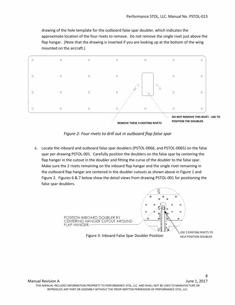
drawing of the hole template for the outboard false spar doubler, which indicates the approximate location of the four rivets to remove. Do not remove the single rivet just above the flap hangar. (Note that the drawing is inverted if you are looking up at the bottom of the wing mounted on the aircraft.)
Figure 2: Four rivets to drill out in outboard flap false spar
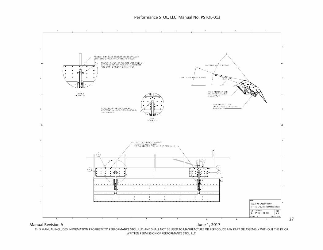
6. Locate the inboard and outboard false spar doublers (PSTOL-0066, and PSTOL-0065) on the false
spar per drawing PSTOL-001. Carefully position the doublers on the false spar by centering the flap hanger in the cutout in the doubler and fitting the curve of the doubler to the false spar. Make sure the 2 rivets remaining on the inboard flap hangar and the single rivet remaining in the outboard flap hangar are centered in the doubler cutouts as shown above in Figure 1 and Figure 2. Figures 6 & 7 below show the detail views from drawing PSTOL-001 for positioning the false spar doublers.
Figure 3: Inboard False Spar Doubler Position
DO NOT REMOVE THIS RIVET. USE TO POSITION THE DOUBLER. REMOVE THESE 4 EXISTING RIVETS
USE 2 EXISTING RIVETS TO HELP POSITION DOUBLER.
Performance STOL, LLC. Manual No. PSTOL-013
9 Manual Revision A June 1, 2017
THIS MANUAL INCLUDES INFORMATION PROPRIETY TO PERFORMANCE STOL, LLC. AND SHALL NOT BE USED TO MANUFACTURE OR REPRODUCE ANY PART OR ASSEMBLY WITHOUT THE PRIOR WRITTEN PERMISSION OF PERFORMANCE STOL, LLC.
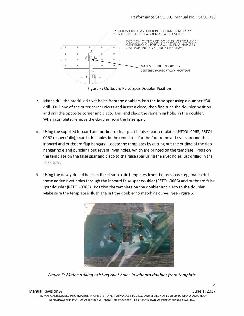
Figure 4: Outboard False Spar Doubler Position
7. Match drill the predrilled rivet holes from the doublers into the false spar using a number #30
drill. Drill one of the outer corner rivets and insert a cleco, then fine tune the doubler position and drill the opposite corner and cleco. Drill and cleco the remaining holes in the doubler. When complete, remove the doubler from the false spar.
8. Using the supplied inboard and outboard clear plastic false spar templates (PSTOL-0068, PSTOL-0067 respectfully), match drill holes in the templates for the four removed rivets around the inboard and outboard flap hangars. Locate the templates by cutting out the outline of the flap hangar hole and punching out several rivet holes, which are printed on the template. Position the template on the false spar and cleco to the false spar using the rivet holes just drilled in the false spar.
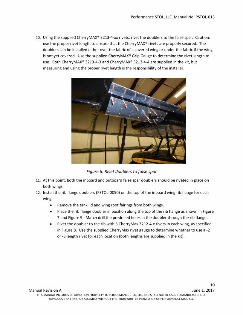
9. Using the newly drilled holes in the clear plastic templates from the previous step, match drill
these added rivet holes through the inboard false spar doubler (PSTOL-0066) and outboard false spar doubler (PSTOL-0065). Position the template on the doubler and cleco to the doubler. Make sure the template is flush against the doubler to match its curve. See Figure 5.
Figure 5: Match drilling existing rivet holes in inboard doubler from template
MAKE SURE EXISTING RIVET IS CENTERED HORIZONTALLY IN CUTOUT.
Performance STOL, LLC. Manual No. PSTOL-013
10 Manual Revision A June 1, 2017
THIS MANUAL INCLUDES INFORMATION PROPRIETY TO PERFORMANCE STOL, LLC. AND SHALL NOT BE USED TO MANUFACTURE OR REPRODUCE ANY PART OR ASSEMBLY WITHOUT THE PRIOR WRITTEN PERMISSION OF PERFORMANCE STOL, LLC.
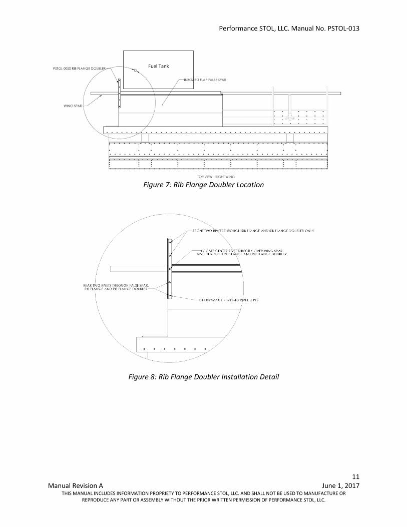
10. Using the supplied CherryMAX® 3213-4-xx rivets, rivet the doublers to the false spar. Caution:
use the proper rivet length to ensure that the CherryMAX® rivets are properly secured. The doublers can be installed either over the fabric of a covered wing or under the fabric if the wing is not yet covered. Use the supplied CherryMAX® Grip Gauge to determine the rivet length to use. Both CherryMAX® 3213-4-3 and CherryMAX® 3213-4-4 are supplied in the kit, but measuring and using the proper rivet length is the responsibility of the installer.
Figure 6: Rivet doublers to false spar
11. At this point, both the inboard and outboard false spar doublers should be riveted in place on both wings.
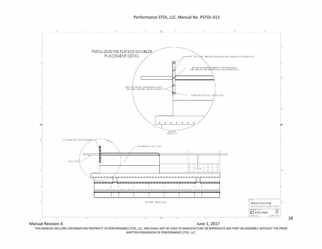
12. Install the rib flange doublers (PSTOL-0050) on the top of the inboard wing rib flange for each wing:
• Remove the tank lid and wing root fairings from both wings. • Place the rib flange doubler in position along the top of the rib flange as shown in Figure
7 and Figure 9. Match drill the predrilled holes in the doubler through the rib flange. • Rivet the doubler to the rib with 5 CherryMax 3212-4-x rivets in each wing, as specified
in Figure 8. Use the supplied CherryMax rivet gauge to determine whether to use a -2 or -3 length rivet for each location (both lengths are supplied in the kit).
Performance STOL, LLC. Manual No. PSTOL-013
11 Manual Revision A June 1, 2017
THIS MANUAL INCLUDES INFORMATION PROPRIETY TO PERFORMANCE STOL, LLC. AND SHALL NOT BE USED TO MANUFACTURE OR REPRODUCE ANY PART OR ASSEMBLY WITHOUT THE PRIOR WRITTEN PERMISSION OF PERFORMANCE STOL, LLC.
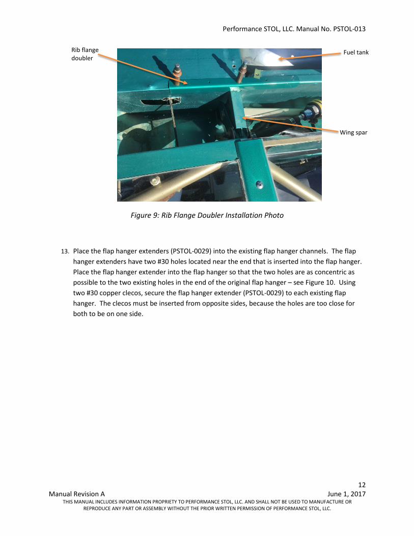
Figure 7: Rib Flange Doubler Location
Figure 8: Rib Flange Doubler Installation Detail
Fuel Tank
Performance STOL, LLC. Manual No. PSTOL-013
12 Manual Revision A June 1, 2017
THIS MANUAL INCLUDES INFORMATION PROPRIETY TO PERFORMANCE STOL, LLC. AND SHALL NOT BE USED TO MANUFACTURE OR REPRODUCE ANY PART OR ASSEMBLY WITHOUT THE PRIOR WRITTEN PERMISSION OF PERFORMANCE STOL, LLC.
Figure 9: Rib Flange Doubler Installation Photo
13. Place the flap hanger extenders (PSTOL-0029) into the existing flap hanger channels. The flap hanger extenders have two #30 holes located near the end that is inserted into the flap hanger. Place the flap hanger extender into the flap hanger so that the two holes are as concentric as possible to the two existing holes in the end of the original flap hanger – see Figure 10. Using two #30 copper clecos, secure the flap hanger extender (PSTOL-0029) to each existing flap hanger. The clecos must be inserted from opposite sides, because the holes are too close for both to be on one side.
Rib flange doubler
Wing spar
Fuel tank
Performance STOL, LLC. Manual No. PSTOL-013
13 Manual Revision A June 1, 2017
THIS MANUAL INCLUDES INFORMATION PROPRIETY TO PERFORMANCE STOL, LLC. AND SHALL NOT BE USED TO MANUFACTURE OR REPRODUCE ANY PART OR ASSEMBLY WITHOUT THE PRIOR WRITTEN PERMISSION OF PERFORMANCE STOL, LLC.
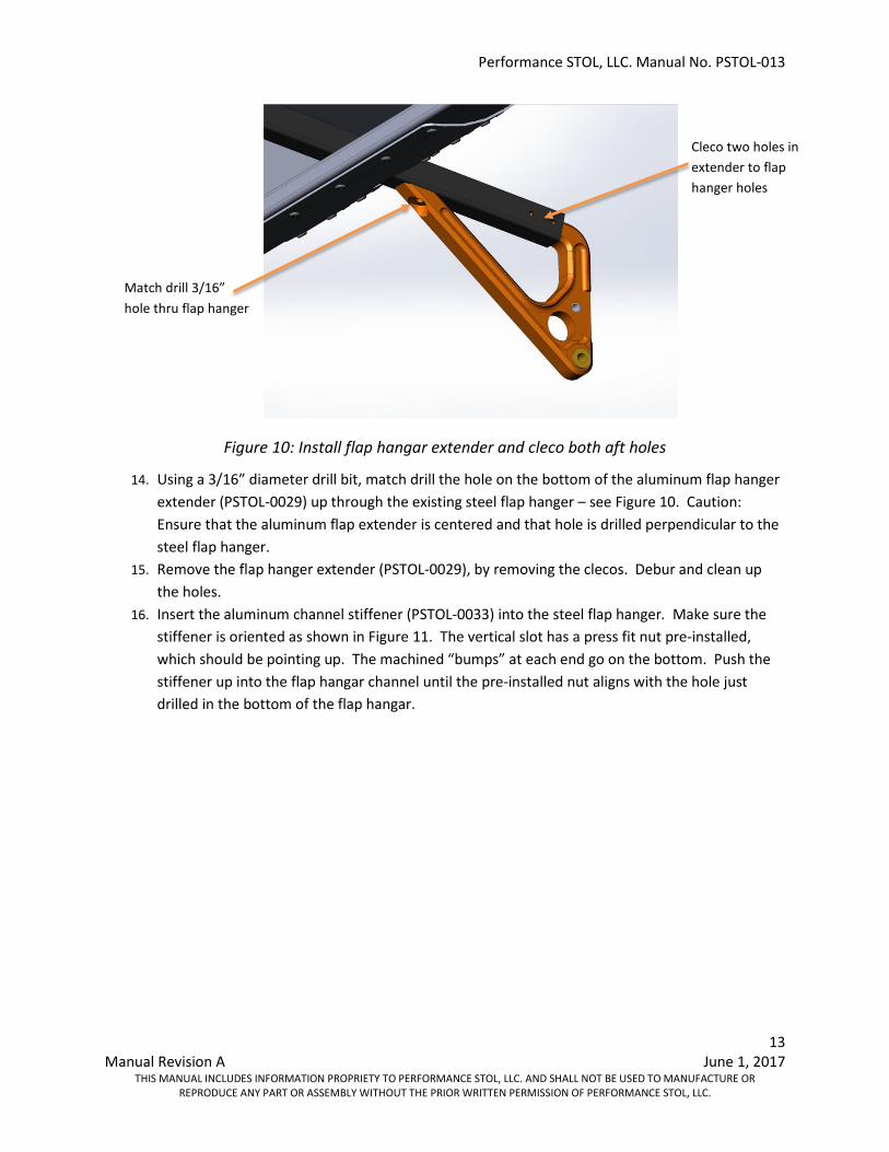
Figure 10: Install flap hangar extender and cleco both aft holes
14. Using a 3/16” diameter drill bit, match drill the hole on the bottom of the aluminum flap hanger extender (PSTOL-0029) up through the existing steel flap hanger – see Figure 10. Caution: Ensure that the aluminum flap extender is centered and that hole is drilled perpendicular to the steel flap hanger.
15. Remove the flap hanger extender (PSTOL-0029), by removing the clecos. Debur and clean up the holes.
16. Insert the aluminum channel stiffener (PSTOL-0033) into the steel flap hanger. Make sure the stiffener is oriented as shown in Figure 11. The vertical slot has a press fit nut pre-installed, which should be pointing up. The machined “bumps” at each end go on the bottom. Push the stiffener up into the flap hangar channel until the pre-installed nut aligns with the hole just drilled in the bottom of the flap hangar.
Match drill 3/16” hole thru flap hanger
Cleco two holes in extender to flap hanger holes
Performance STOL, LLC. Manual No. PSTOL-013
14 Manual Revision A June 1, 2017
THIS MANUAL INCLUDES INFORMATION PROPRIETY TO PERFORMANCE STOL, LLC. AND SHALL NOT BE USED TO MANUFACTURE OR REPRODUCE ANY PART OR ASSEMBLY WITHOUT THE PRIOR WRITTEN PERMISSION OF PERFORMANCE STOL, LLC.
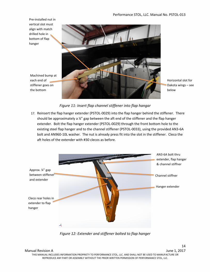
Figure 11: Insert flap channel stiffener into flap hangar
17. Reinsert the flap hanger extender (PSTOL-0029) into the flap hanger behind the stiffener. There should be approximately a ¼” gap between the aft end of the stiffener and the flap hanger extender. Bolt the flap hanger extender (PSTOL-0029) through the front bottom hole to the existing steel flap hanger and to the channel stiffener (PSTOL-0033), using the provided AN3-6A bolt and AN960-10L washer. The nut is already press fit into the slot in the stiffener. Cleco the aft holes of the extender with #30 clecos as before.
Figure 12: Extender and stiffener bolted to flap hanger
Pre-installed nut in vertical slot must align with match drilled hole in bottom of flap hanger
Horizontal slot for Dakota wings – see below
AN3-6A bolt thru extender, flap hanger & channel stiffner
Cleco rear holes in extender to flap hanger
Channel stiffner
Hanger extender
Machined bump at each end of stiffener goes on the bottom
Approx. ¼” gap between stiffener and extender
Performance STOL, LLC. Manual No. PSTOL-013
15 Manual Revision A June 1, 2017
THIS MANUAL INCLUDES INFORMATION PROPRIETY TO PERFORMANCE STOL, LLC. AND SHALL NOT BE USED TO MANUFACTURE OR REPRODUCE ANY PART OR ASSEMBLY WITHOUT THE PRIOR WRITTEN PERMISSION OF PERFORMANCE STOL, LLC.
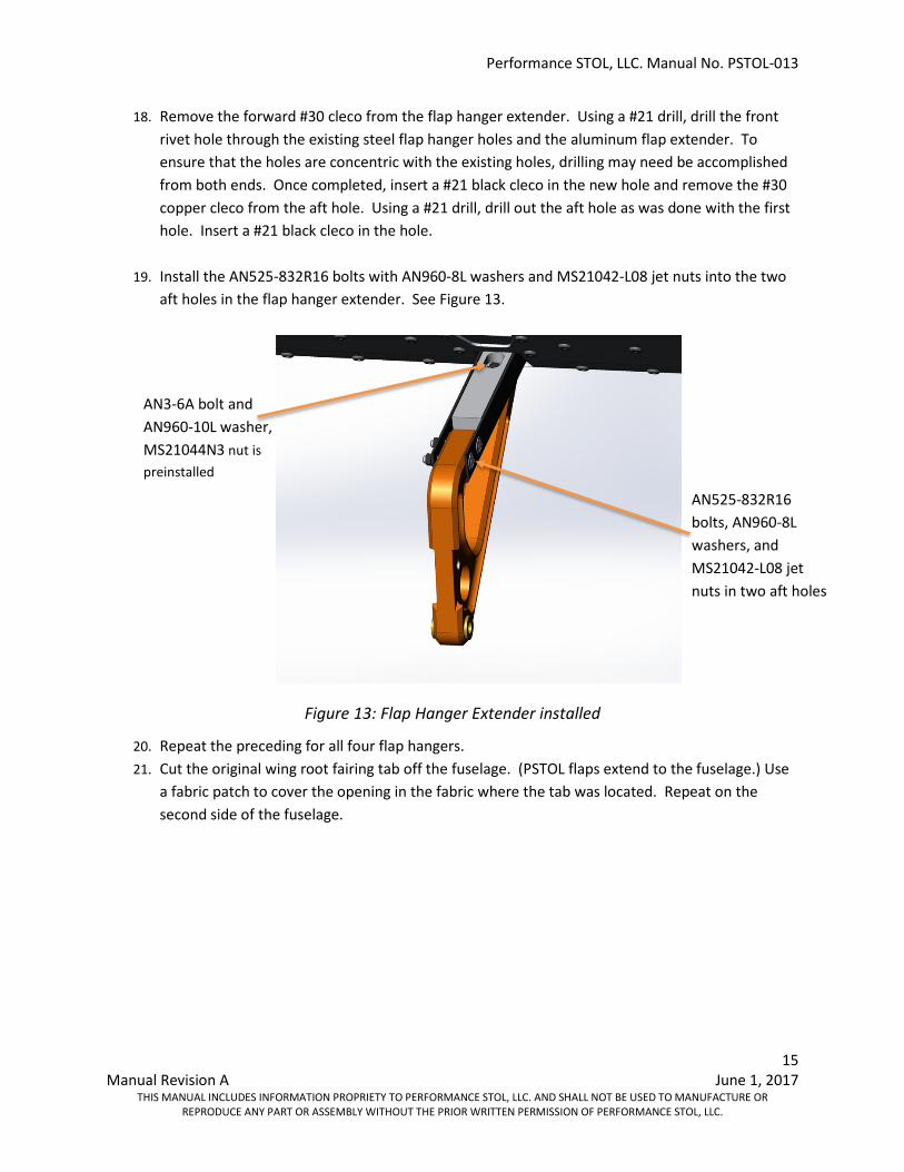
18. Remove the forward #30 cleco from the flap hanger extender. Using a #21 drill, drill the front rivet hole through the existing steel flap hanger holes and the aluminum flap extender. To ensure that the holes are concentric with the existing holes, drilling may need be accomplished from both ends. Once completed, insert a #21 black cleco in the new hole and remove the #30 copper cleco from the aft hole. Using a #21 drill, drill out the aft hole as was done with the first hole. Insert a #21 black cleco in the hole.
19. Install the AN525-832R16 bolts with AN960-8L washers and MS21042-L08 jet nuts into the two
aft holes in the flap hanger extender. See Figure 13.
Figure 13: Flap Hanger Extender installed
20. Repeat the preceding for all four flap hangers. 21. Cut the original wing root fairing tab off the fuselage. (PSTOL flaps extend to the fuselage.) Use
a fabric patch to cover the opening in the fabric where the tab was located. Repeat on the second side of the fuselage.
AN525-832R16 bolts, AN960-8L washers, and MS21042-L08 jet nuts in two aft holes
AN3-6A bolt and AN960-10L washer, MS21044N3 nut is preinstalled
Performance STOL, LLC. Manual No. PSTOL-013
16 Manual Revision A June 1, 2017
THIS MANUAL INCLUDES INFORMATION PROPRIETY TO PERFORMANCE STOL, LLC. AND SHALL NOT BE USED TO MANUFACTURE OR REPRODUCE ANY PART OR ASSEMBLY WITHOUT THE PRIOR WRITTEN PERMISSION OF PERFORMANCE STOL, LLC.
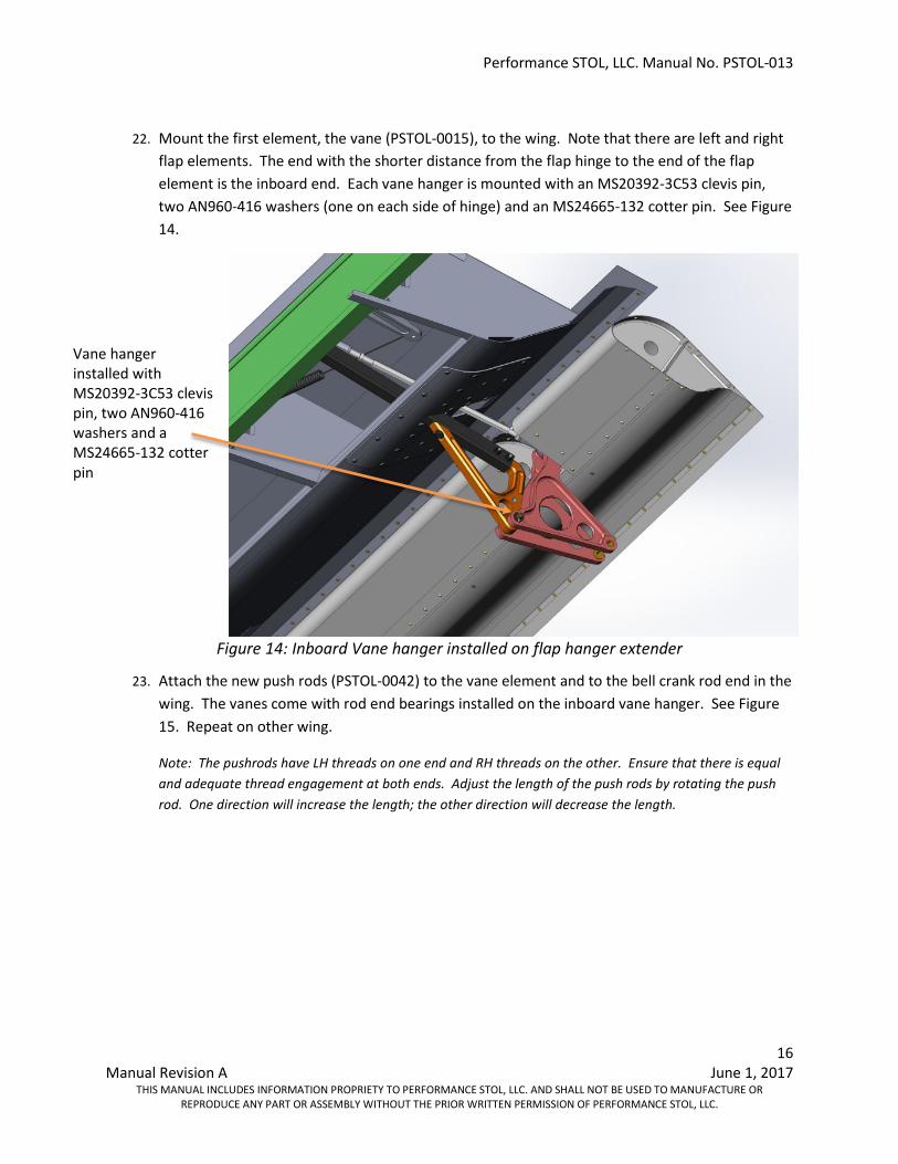
22. Mount the first element, the vane (PSTOL-0015), to the wing. Note that there are left and right
flap elements. The end with the shorter distance from the flap hinge to the end of the flap element is the inboard end. Each vane hanger is mounted with an MS20392-3C53 clevis pin, two AN960-416 washers (one on each side of hinge) and an MS24665-132 cotter pin. See Figure 14.
Figure 14: Inboard Vane hanger installed on flap hanger extender
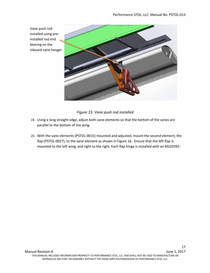
23. Attach the new push rods (PSTOL-0042) to the vane element and to the bell crank rod end in the wing. The vanes come with rod end bearings installed on the inboard vane hanger. See Figure 15. Repeat on other wing.
Note: The pushrods have LH threads on one end and RH threads on the other. Ensure that there is equal and adequate thread engagement at both ends. Adjust the length of the push rods by rotating the push rod. One direction will increase the length; the other direction will decrease the length.
Vane hanger installed with MS20392-3C53 clevis pin, two AN960-416 washers and a MS24665-132 cotter pin
Performance STOL, LLC. Manual No. PSTOL-013
17 Manual Revision A June 1, 2017
THIS MANUAL INCLUDES INFORMATION PROPRIETY TO PERFORMANCE STOL, LLC. AND SHALL NOT BE USED TO MANUFACTURE OR REPRODUCE ANY PART OR ASSEMBLY WITHOUT THE PRIOR WRITTEN PERMISSION OF PERFORMANCE STOL, LLC.
Figure 15: Vane push rod installed
24. Using a long straight edge, adjust both vane elements so that the bottom of the vanes are parallel to the bottom of the wing.
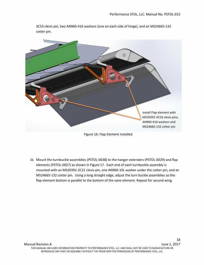
25. With the vane elements (PSTOL-0015) mounted and adjusted, mount the second element, the flap (PSTOL-0027), to the vane element as shown in Figure 16. Ensure that the left flap is mounted to the left wing, and right to the right. Each flap hinge is installed with an MS20392-
Vane push rod installed using pre-installed rod end bearing on the inboard vane hanger
Performance STOL, LLC. Manual No. PSTOL-013
18 Manual Revision A June 1, 2017
THIS MANUAL INCLUDES INFORMATION PROPRIETY TO PERFORMANCE STOL, LLC. AND SHALL NOT BE USED TO MANUFACTURE OR REPRODUCE ANY PART OR ASSEMBLY WITHOUT THE PRIOR WRITTEN PERMISSION OF PERFORMANCE STOL, LLC.
3C53 clevis pin, two AN960-416 washers (one on each side of hinge), and an MS24665-132 cotter pin.
Figure 16: Flap Element installed
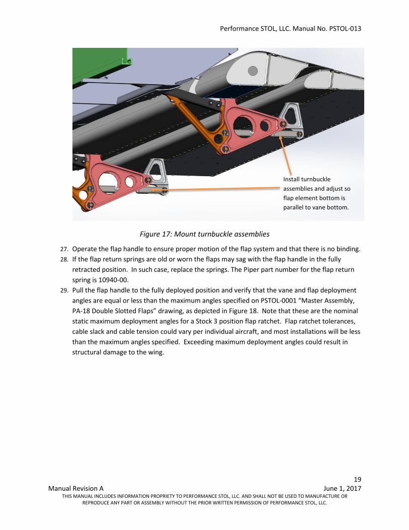
26. Mount the turnbuckle assemblies (PSTOL-0038) to the hanger extenders (PSTOL-0029) and flap elements (PSTOL-0027) as shown in Figure 17. Each end of each turnbuckle assembly is mounted with an MS20392-2C21 clevis pin, one AN960-10L washer under the cotter pin, and an MS24665-132 cotter pin. Using a long straight edge, adjust the turn buckle assemblies so the flap element bottom is parallel to the bottom of the vane element. Repeat for second wing.
Install Flap element with MS20392-3C53 clevis pins, AN960-416 washers and MS24665-132 cotter pin
Performance STOL, LLC. Manual No. PSTOL-013
19 Manual Revision A June 1, 2017
THIS MANUAL INCLUDES INFORMATION PROPRIETY TO PERFORMANCE STOL, LLC. AND SHALL NOT BE USED TO MANUFACTURE OR REPRODUCE ANY PART OR ASSEMBLY WITHOUT THE PRIOR WRITTEN PERMISSION OF PERFORMANCE STOL, LLC.
Figure 17: Mount turnbuckle assemblies
27. Operate the flap handle to ensure proper motion of the flap system and that there is no binding. 28. If the flap return springs are old or worn the flaps may sag with the flap handle in the fully
retracted position. In such case, replace the springs. The Piper part number for the flap return spring is 10940-00.
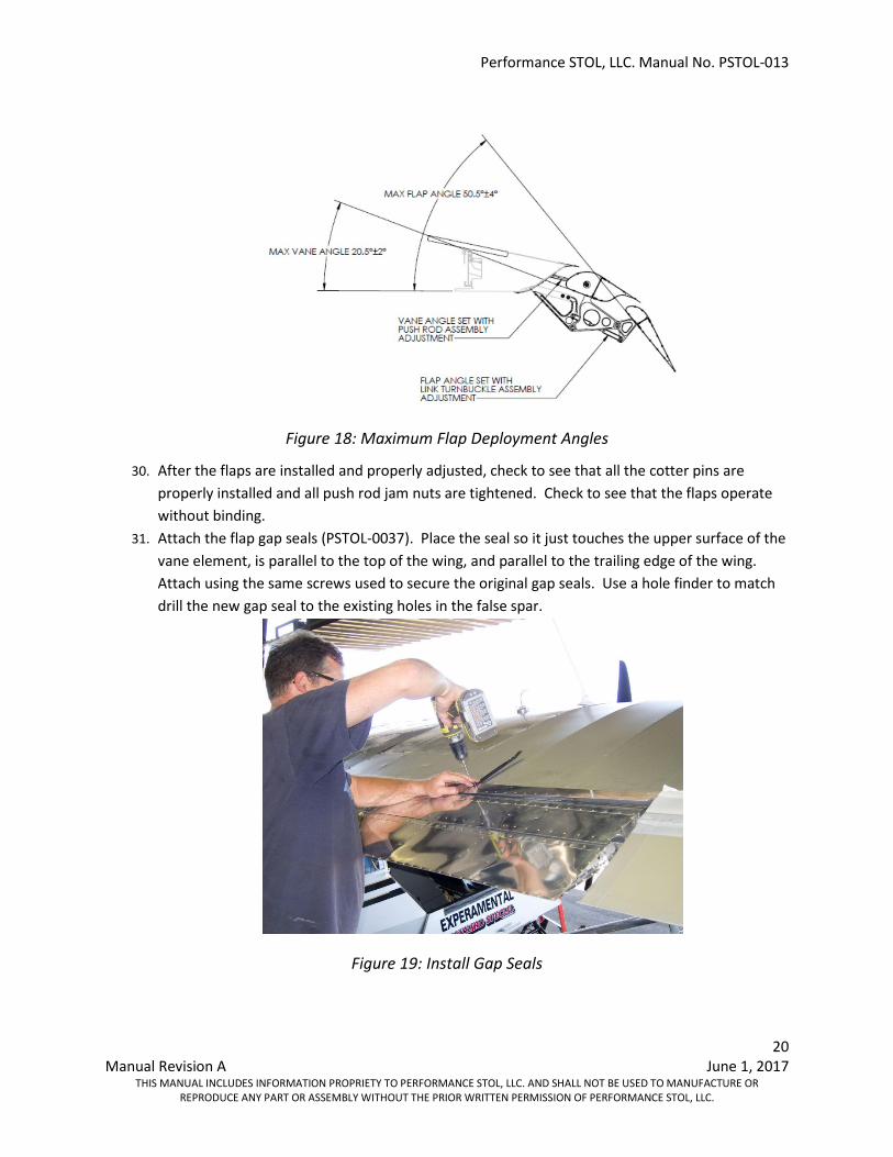
29. Pull the flap handle to the fully deployed position and verify that the vane and flap deployment angles are equal or less than the maximum angles specified on PSTOL-0001 “Master Assembly, PA-18 Double Slotted Flaps” drawing, as depicted in Figure 18. Note that these are the nominal static maximum deployment angles for a Stock 3 position flap ratchet. Flap ratchet tolerances, cable slack and cable tension could vary per individual aircraft, and most installations will be less than the maximum angles specified. Exceeding maximum deployment angles could result in structural damage to the wing.
Install turnbuckle assemblies and adjust so flap element bottom is parallel to vane bottom.
Performance STOL, LLC. Manual No. PSTOL-013
20 Manual Revision A June 1, 2017
THIS MANUAL INCLUDES INFORMATION PROPRIETY TO PERFORMANCE STOL, LLC. AND SHALL NOT BE USED TO MANUFACTURE OR REPRODUCE ANY PART OR ASSEMBLY WITHOUT THE PRIOR WRITTEN PERMISSION OF PERFORMANCE STOL, LLC.
Figure 18: Maximum Flap Deployment Angles
30. After the flaps are installed and properly adjusted, check to see that all the cotter pins are properly installed and all push rod jam nuts are tightened. Check to see that the flaps operate without binding.
31. Attach the flap gap seals (PSTOL-0037). Place the seal so it just touches the upper surface of the vane element, is parallel to the top of the wing, and parallel to the trailing edge of the wing. Attach using the same screws used to secure the original gap seals. Use a hole finder to match drill the new gap seal to the existing holes in the false spar.
Figure 19: Install Gap Seals
Performance STOL, LLC. Manual No. PSTOL-013
21 Manual Revision A June 1, 2017
THIS MANUAL INCLUDES INFORMATION PROPRIETY TO PERFORMANCE STOL, LLC. AND SHALL NOT BE USED TO MANUFACTURE OR REPRODUCE ANY PART OR ASSEMBLY WITHOUT THE PRIOR WRITTEN PERMISSION OF PERFORMANCE STOL, LLC.
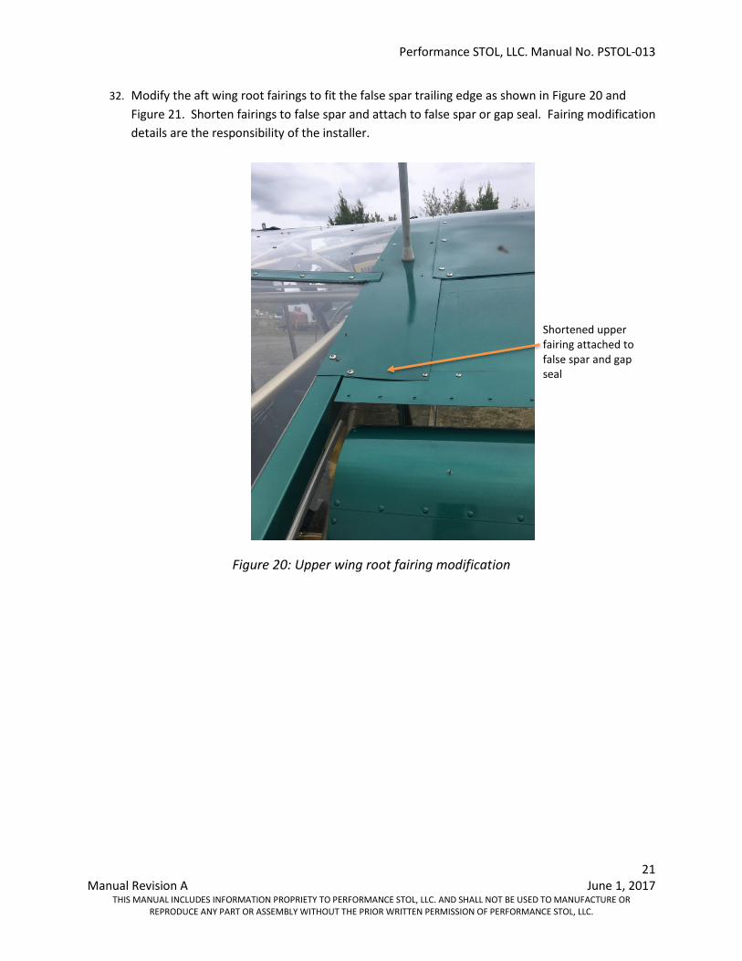
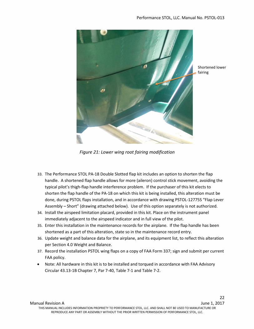
32. Modify the aft wing root fairings to fit the false spar trailing edge as shown in Figure 20 and Figure 21. Shorten fairings to false spar and attach to false spar or gap seal. Fairing modification details are the responsibility of the installer.
Figure 20: Upper wing root fairing modification
Shortened upper fairing attached to false spar and gap seal
Performance STOL, LLC. Manual No. PSTOL-013
22 Manual Revision A June 1, 2017
THIS MANUAL INCLUDES INFORMATION PROPRIETY TO PERFORMANCE STOL, LLC. AND SHALL NOT BE USED TO MANUFACTURE OR REPRODUCE ANY PART OR ASSEMBLY WITHOUT THE PRIOR WRITTEN PERMISSION OF PERFORMANCE STOL, LLC.
Figure 21: Lower wing root fairing modification
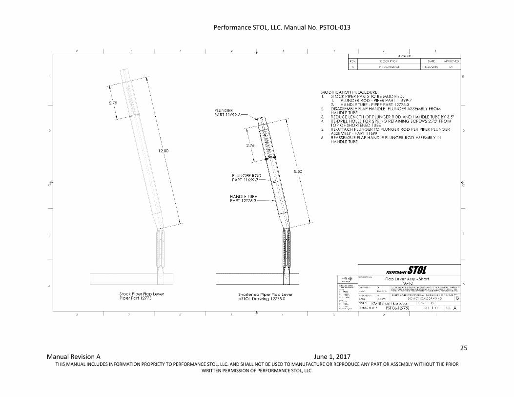
33. The Performance STOL PA-18 Double Slotted flap kit includes an option to shorten the flap handle. A shortened flap handle allows for more (aileron) control stick movement, avoiding the typical pilot’s thigh-flap handle interference problem. If the purchaser of this kit elects to shorten the flap handle of the PA-18 on which this kit is being installed, this alteration must be done, during PSTOL flaps installation, and in accordance with drawing PSTOL-12775S “Flap Lever Assembly – Short” (drawing attached below). Use of this option separately is not authorized.
34. Install the airspeed limitation placard, provided in this kit. Place on the instrument panel immediately adjacent to the airspeed indicator and in full view of the pilot.
35. Enter this installation in the maintenance records for the airplane. If the flap handle has been shortened as a part of this alteration, state so in the maintenance record entry.
36. Update weight and balance data for the airplane, and its equipment list, to reflect this alteration per Section 4.0 Weight and Balance.
37. Record the installation PSTOL wing flaps on a copy of FAA Form 337; sign and submit per current FAA policy.
• Note: All hardware in this kit is to be installed and torqued in accordance with FAA Advisory Circular 43.13-1B Chapter 7, Par 7-40, Table 7-1 and Table 7-2.
Shortened lower fairing
Performance STOL, LLC. Manual No. PSTOL-013
23 Manual Revision A June 1, 2017
THIS MANUAL INCLUDES INFORMATION PROPRIETY TO PERFORMANCE STOL, LLC. AND SHALL NOT BE USED TO MANUFACTURE OR REPRODUCE ANY PART OR ASSEMBLY WITHOUT THE PRIOR WRITTEN PERMISSION OF PERFORMANCE STOL, LLC.
Weight and Balance
The Performance STOL PA-18 Double Slotted Flap system has an exchange weight increase of 12 lbs when exchanged for the OEM flaps. The C.G. location for the added weight is at 56.0 inches aft of the leading edge of the wing. Add this weight and moment arm to the latest aircraft Weight and Balance Sheet and retain it in the aircraft.
Weight of Performance STOL, PA-18, Double Slotted flaps: 21 lb 12 oz - Weight of PA-18 OEM flaps: 9 lb 12 oz Added exchange weight: 12 lb 00 oz
Trouble Shooting
Problem: The flap elements and/or gap seal rub and cause wear marks.
Correction: Bend the vane and/or flap elements and/or gap seal trailing edges up where wear is occurring. Bend up until the wear/rubbing is eliminated. Make sure not to crease any component.
Problem: The flaps do not deploy down to the specified angle.
Correction: Tighten the flap cable turn buckles to eliminate any slop in the cable. Make sure that the cables are not tightened so much as to move the flap bell cranks off their stops when the flaps are not deployed. It is possible that the flap pawl and or ratchet are worn and are in need of replacement.
Problem: The flaps do not retract flush with the bottom of the wing when fully retracted.
Correction: The flap springs are worn and in need of replacement. As the flap springs age, they lose stiffness. Drooping flaps in the static non-retracted position is not a hazard to flight, but may be problematic when parked outside in strong winds.
Problem: The aircraft turns to the left or right and/or the inclinator ball is not centered in cruise flight.
Correction: The flaps are not adjusted properly in the non-deployed position. Adjust the pushrods so that the vane and flap elements are parallel to the bottom of the wing. The addition of the Performance STOL flaps should not alter the aircraft rigging as long as the bottom of each element is parallel to the bottom of their respective wing. Ensure that the aircraft is properly rigged according to the aircraft’s TCDS.
Problem: The bottom of the flaps are lower or higher than the bottom of the wing.
Performance STOL, LLC. Manual No. PSTOL-013
24 Manual Revision A June 1, 2017
THIS MANUAL INCLUDES INFORMATION PROPRIETY TO PERFORMANCE STOL, LLC. AND SHALL NOT BE USED TO MANUFACTURE OR REPRODUCE ANY PART OR ASSEMBLY WITHOUT THE PRIOR WRITTEN PERMISSION OF PERFORMANCE STOL, LLC.
Correction: All aircraft have build tolerances and they vary drastically from one aircraft to another. There is no correction for this problem and it is acceptable. It is important that the bottom of the flap elements are parallel with the bottom of the wing.
Drawings and Diagrams
Descriptive Data List
Document Title Document Number Revision Level Pages Date Instructions for Continued Airworthiness Including Installation, maintenance and Service Instructions
Manual PSTOL-010 IR 1-17 9/6/2016
Flap Lever Assembly - Short Drawing PSTOL-12775S
IR 8/26/2015
PA-18 Double Slotted Flaps - Master Assembly
Drawing PSTOL-0001
F 1-2 9/11/2016
Flight Manual Supplement Manual PSTOL-011 IR 1-4 9/6/2016 AML Manual PSTOL-012 IR 1 9/6/2016
Engineering Changes and Amendments
In the event that a change or amendment is made to the design, components, or procedures contained within this manual or the STC that affect airworthiness of the flap installation; Performance STOL, LLC. will notify the recorded owner in writing of the affected element(s) and provide the necessary data for compliance.
Performance STOL, LLC. Manual No. PSTOL-013
25 Manual Revision A June 1, 2017
THIS MANUAL INCLUDES INFORMATION PROPRIETY TO PERFORMANCE STOL, LLC. AND SHALL NOT BE USED TO MANUFACTURE OR REPRODUCE ANY PART OR ASSEMBLY WITHOUT THE PRIOR WRITTEN PERMISSION OF PERFORMANCE STOL, LLC.
Performance STOL, LLC. Manual No. PSTOL-013
26 Manual Revision A June 1, 2017
THIS MANUAL INCLUDES INFORMATION PROPRIETY TO PERFORMANCE STOL, LLC. AND SHALL NOT BE USED TO MANUFACTURE OR REPRODUCE ANY PART OR ASSEMBLY WITHOUT THE PRIOR WRITTEN PERMISSION OF PERFORMANCE STOL, LLC.
Performance STOL, LLC. Manual No. PSTOL-013
27 Manual Revision A June 1, 2017
THIS MANUAL INCLUDES INFORMATION PROPRIETY TO PERFORMANCE STOL, LLC. AND SHALL NOT BE USED TO MANUFACTURE OR REPRODUCE ANY PART OR ASSEMBLY WITHOUT THE PRIOR WRITTEN PERMISSION OF PERFORMANCE STOL, LLC.
Performance STOL, LLC. Manual No. PSTOL-013
28 Manual Revision A June 1, 2017
THIS MANUAL INCLUDES INFORMATION PROPRIETY TO PERFORMANCE STOL, LLC. AND SHALL NOT BE USED TO MANUFACTURE OR REPRODUCE ANY PART OR ASSEMBLY WITHOUT THE PRIOR WRITTEN PERMISSION OF PERFORMANCE STOL, LLC.
Performance STOL, LLC. Manual No. PSTOL-013
29 Manual Revision A June 1, 2017
THIS MANUAL INCLUDES INFORMATION PROPRIETY TO PERFORMANCE STOL, LLC. AND SHALL NOT BE USED TO MANUFACTURE OR REPRODUCE ANY PART OR ASSEMBLY WITHOUT THE PRIOR WRITTEN PERMISSION OF PERFORMANCE STOL, LLC.
-END-


![[013] ass 013 [1880]](https://img.pdfslide.us/doc/110x75/5695d38c1a28ab9b029e54d8/013-ass-013-1880.jpg)