Embed Size (px)
Citation preview
CORROSION ENGINEERING SECTION
640 CORROSION—JULY 20030010-9312/03/000127/$5.00+$0.50/0
© 2003, NACE International
Submitted for publication April 2002; in revised form, January2003. Presented as paper no. 02048 at CORROSION 2002, April2002, Denver, CO.
‡ Corresponding author.* Fontana Corrosion Center, The Ohio State University, 477 Watts
Hall, 2041 College Rd., Columbus, OH 43210.** Edison Welding Institute, 1250 Arthur E. Adams Dr., Columbus,
OH 43221.*** CC Technologies, Inc., 6141 Avery Rd., Dublin, OH 43016.
Performance of Welded High-Strength Low-AlloySteels in Sour Environments
G.M. Omweg,* G.S. Frankel,‡,* W.A. Bruce,** J.E. Ramirez,** and G. Koch***
ABSTRACT
Sulfide stress cracking (SSC) susceptibility of gas metal arcwelded API 5L X70 and X80 line pipe steel was tested usingstandard and modified NACE TM0177 (Method A) testing.Two applied stresses and three concentrations of dissolvedhydrogen sulfide (H2S) were used. The effect of peak weldhardness was examined by using three weld conditions. Sev-eral welds meeting the HRC 22 requirement failed by SSC.Welds containing hardness exceeding 248 HV were resistantto SSC at low H2S concentrations. The centerline segregationregion (CSR) observed in the X70 pipe steel played an impor-tant role in the SSC and hydrogen-induced cracking (HIC)susceptibility of the welds. The X80 material was more sus-ceptible at lower hardness values due to localized softeningduring welding, and subsequent plastic deformation uponloading. An extrapolation to in-service weldments indicatedthat the NACE MR0175 requirements may be conservative forhigh-strength low-alloy steel welds not in direct contact withthe sour environment.
KEY WORDS: hydrogen embrittlement, hydrogen sulfidecracking test, pipelines, steel, sulfide stress cracking, weld
INTRODUCTION
Steels with hardness higher than HRC 22 have beenshown to be susceptible to sulfide stress cracking(SSC), a form of hydrogen embrittlement (HE),1-3 insour service environments. The suitable sour servicematerials listed in NACE MR01754 are based on theirresistance to SSC either in actual field applicationsor on laboratory testing performed using the NACETM0177 test method, which is a severe, acceleratedexposure test.5 Many high-strength low-alloy (HSLA)steels are precluded from NACE MR0175, especiallyin the as-welded condition, due to either high parentmaterial hardness or to the formation of localizedhigh-hardness weld regions in the weld heat-affectedzone (HAZ). HAZ regions have exhibited high suscep-tibility to SSC in both service and laboratory environ-ments.2 Because of the inherent toughness affordedby HSLA steels, the NACE MR0175 requirement maybe overly conservative for this class of alloys.
Oil and gas transport conditions are becomingincreasingly sour (higher hydrogen sulfide [H2S] con-centrations) and the use of higher strength HSLAgrades is prevented where NACE MR0175 is used asa governmental regulation. The performance of pipe-line girth welds used to connect pipe segments in thefield is of interest. Multi-pass circumferential girthwelds cause tempering in underlying hard HAZ re-gions, leaving the hardest HAZ regions in the finaluntempered cap passes. On the pipeline exterior,welds are exposed to lower hydrogen concentrations
CORROSION ENGINEERING SECTION
CORROSION—Vol. 59, No. 7 641
than weld regions in contact with the sour environ-ment on the inner pipe surface. SSC is a HE mecha-nism, so higher hardness values (exceeding HRC 22)should be tolerable in hard weld cap regions, whichare exposed to relatively low hydrogen concentra-tions. In fact, it has been shown that hard externalweld regions exceeding 300 HV (248 HV = HRC 22)were resistant to SSC in a stressed pipe filled withthe NACE test solution.6 This investigation wasaimed at assessing the conservatism of the NACErequirements for HSLA weldments. Aspects of thiswork focused on welding parameters and microstruc-ture are given elsewhere.7-8
EXPERIMENTAL PROCEDURES
The materials investigated were API 5L X70 andX80 spiral-welded HSLA line pipe materials. Thesealloys are designated by their specified minimumyield strength (e.g., YS for X70 is 70 ksi). The compo-sitions of the alloys are given in Table 1 along withvalues of carbon equivalents CEIIW and Pcm, and thepertinent pipe dimensions, including outer diameter(OD) and wall thickness (t). The carbon equivalent isconvenient for comparing the weldability of differentsteels. The X80 was very low in carbon, just abovesaturation in ferrite (0.022 wt% C) at the eutectoidtemperature. Both alloys were low-sulfur steels.9
The primary carbo-nitride (CN) forming elementsin the X70 and X80 were vanadium and niobium,respectively.
The as-received microstructure of the X70 pipesteel consisted of banded, fine-grained ferrite + pearl-ite as shown by the long transverse section in Figure1(a). The X70 pipe steel contained a heavily bandedcenterline segregation region (CSR) characterized bythicker, more continuous banding, as shown in Fig-ure 1(b). The CSR region was compositionally differ-ent due to segregation of elements like C and Mn.10
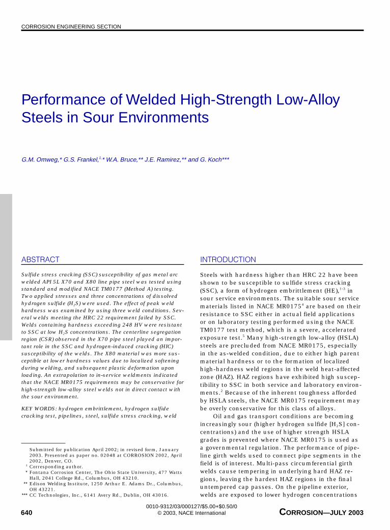
As a result, the alloy-rich bands are more hardenablethan the alloy-lean bands. In contrast, the X80 didnot contain large amounts of carbide, a bandedmicrostructure, or a visible CSR. Figure 2 revealsfine-grained ferrite, large secondary ferrite grains,and granular bainite in the X80 parent material.Although susceptibility to SSC generally increaseswith increasing hardness, some microstructures aremore susceptible to cracking than others at the same
hardness. For example, tempered martensite is moreresistant than tempered bainite or mixed microstruc-ture at the same hardness level. The observed differ-ences in microstructure between X70 and X80 steelpipes is a result of different chemical compositionsand different steel processing routes.
The through-wall hardness profile of each pipe-line steel was measured using the Rockwell C andVickers 10-kg hardness test methods. Neither parentmaterial exceeded HRC 22.8
TABLE 1Base Alloy Compositions and Pipe Dimensions
Alloy C Mn P S Si Ni Cr Mo Cu V Al Ti Nb CEIIW Pcm OD(A) t(A)
X70 0.16 1.6 0.013 <0.003 0.32 <0.01 0.02 <0.01 0.01 0.08 0.03 0.01 0.04 0.47 0.26 34.75 0.75X80 0.029 1.86 0.008 0.003 0.35 0.11 0.06 0.25 0.22 <0.005 0.03 0.02 0.10 0.45 0.170 42 0.55
(A) Measurements in inches.
API 5L Steel Pipeline Compositions (wt%) and Dimensions
(a)
(b)
FIGURE 1. X70 long transverse section, 2% nital etch (a) fine grainedferrite (F) and pearlite bands (P) and (b) CSR.
CORROSION ENGINEERING SECTION
642 CORROSION—JULY 2003
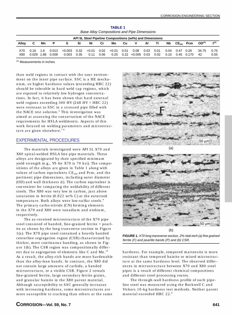
Because of difficulties in making actual girthwelds on large pipe sections without the proper auto-mated gas metal arc welding (GMAW) equipment,simulated girth welds were used for this work. Two6-in.-by-24-in. (15.2-cm-by-61-cm) unflattenedplates cut from the pipe stock were utilized for eachjoint. The plates were tack-welded to a 2-in. (5.1-cm)-thick steel plate to provide the necessary constraintduring cooling. A schematic of the weld geometry isshown in Figure 3. The joint geometry was chosen to
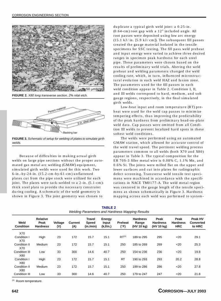
duplicate a typical girth weld joint: a 0.25-in.(0.64-cm) root gap with a 12° included angle. Allroot passes were deposited using low arc energy(15.1 kJ/in. [5.9 kJ/cm]). The subsequent fill passescreated the gauge material isolated in the tensilespecimens for SSC testing. The fill pass weld preheatand input energy were varied to achieve three desiredranges in specimen peak hardness for each steelpipe. These parameters were chosen based on theresults of preliminary weld trials. Altering the weldpreheat and welding parameters changed the weldcooling rate, which, in turn, influenced microstruc-tural evolution in each weld HAZ and fusion zone.The parameters used for the fill passes in eachweld condition appear in Table 2. Condition I, II,and III welds correspond to hard, medium, and softgauge regions, respectively, in the final simulatedgirth welds.
Low-heat input and room temperature (RT) pre-heat were used for the weld cap passes to minimizetempering effects, thus improving the predictabilityof the peak hardness from preliminary bead-on-plateweld data. Cap passes were omitted from all Condi-tion III welds to prevent localized hard spots in thesesoftest weld conditions.
The welds were performed using an automatedGMAW station, which allowed for accurate control ofthe weld travel speed. The pertinent welding processparameters common to all welds (both X70 and X80)appear in Table 3. The typical composition for theER 70S-3 filler metal wire is 0.08% C, 1.1% Mn, and0.6% Si. The joints were milled flat on the upper andlower surfaces and cut into plates for radiographicdefect screening. Transverse weld tensile test speci-mens were machined in accordance with the specifi-cations in NACE TM0177-A. The weld metal regionwas centered in the gauge length of the tensile speci-mens as shown schematically in Figure 3. Hardnessmapping across each weld was performed to system-
TABLE 2Welding Parameters and Hardness Mapping Results
Relative Travel Energy Hardness Peak Peak Peak HVWeld Peak Voltage Current Speed Input Preheat Range Hardness Hardness Converted
Condition Hardness (V) (A) (in./min) (kJ/in.) (°F) (HV 10 kg) (HV 10 kg) HRC to HRC
X70Condition I High 23 172 15.7 15.1 RT(A) 189 to 295 295 <20 29.1
X70Condition II Medium 23 172 15.7 15.1 250 185 to 269 269 <20 25.3
X70Condition III Low 33 300 14.6 40.7 250 154 to 236 236 <20 19.8
X80Condition I High 23 172 15.7 15.1 RT 190 to 293 293 20.2 28.8
X80Condition II Medium 23 172 15.7 15.1 250 199 to 286 286 <20 27.8
X80Condition III Low 33 300 14.6 40.7 250 179 to 247 247 <20 21.8
(A) Room temperature.
FIGURE 2. X80 long transverse section, 2% nital etch.
FIGURE 3. Schematic of setup for welding of plates to simulate girthwelds.
CORROSION ENGINEERING SECTION
CORROSION—Vol. 59, No. 7 643
atically quantify both the peak weld hardness andhardness distribution in the tensile samples. Specif-ics concerning the hardness mapping procedure arediscussed elsewhere.7-8
SSC resistance was evaluated using a test matrixin which weld hardness, applied stress, and H2S con-centration and base material were varied. X70 andX80 plates were welded with three weld conditions toproduce a range in specimen peak weld hardness.Two stresses, 80% or 100% of the specified minimumparent yield, were applied to the samples. These highstresses were used to duplicate the high residual ten-sile stresses encountered in as-welded in-serviceweldments.11 The NACE TM0177-A solution was usedas a base solution: 5 wt% sodium chloride (NaCl) +0.5 wt% glacial acetic acid (CH3COOH) in deionizedwater.5 A range in H2S concentration was achieved bysaturating the solution with different gas mixtures:100%, 30%, or 10% H2S (balance N2). The conditionof 100% H2S exactly reproduced the standard NACETM0177-A test condition, but the H2S-N2 mixturescreated a major modification. Proving rings wereused for static load application and nitrogen wasused for solution deaeration. The time-to-failure(TTF) for complete fractures was measured automati-cally. All testing procedures outlined in NACETM0177 were followed, except the fact that dilutedH2S gas mixtures were used for several testingschedules. The H2S testing was performed in aspecial H2S lab.
After 720 h (30 days) or complete fracture, eachspecimen was removed from the respective corrosioncell. Any corrosion product was removed from theshanks of each tensile bar with an abrasive pad. Thegauge was not abrasively treated, but was rubbedvigorously by hand with a rubber glove. The masswas measured for weight-loss determination. Dimen-sional measurements were made on each sampleto determine the exposure area for calculation ofcorrosion rate.7
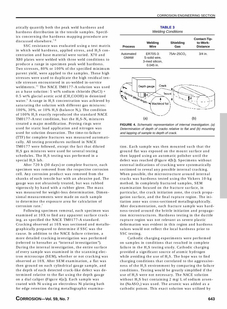
Following specimen removal, each specimen wasexamined at 10X to find any apparent surface crack-ing, as specified the NACE TM0177-A standard.Cracking observed at 10X was sectioned and metallo-graphically prepared to determine if SSC was thecause. In addition to the NACE failure criterion, amore detailed cracking investigation was performed(referred to hereafter as “internal investigation”).During the internal investigation, the entire surfaceof every sample was examined in the scanning elec-tron microscope (SEM), whether or not cracking wasobserved at 10X. After SEM examination, a flat wasthen ground on each cylindrical gauge sample, andthe depth of each detected crack-like defect was de-termined relative to the flat using the depth gaugeon a dial caliper (Figure 4[a]). Each sample wascoated with Ni using an electroless Ni plating bathfor edge retention during metallographic examina-
tion. Each sample was then mounted such that theground flat was exposed on the mount surface andthen lapped using an automatic polisher until thedefect was reached (Figure 4[b]). Specimens withoutexternal indications of cracking were systematicallysectioned to reveal any possible internal cracking.When possible, the microstructure around internalcracks was hardness tested using the Vickers 10-kgmethod. In completely fractured samples, SEMexamination focused on the fracture surface, inparticular, the crack initiation zone, the crack propa-gation surface, and the final rupture region. The ini-tiation zone was cross-sectioned metallographically.After documentation, each fracture sample was hard-ness-tested around the brittle initiation and propaga-tion microstructures. Hardness testing in the ductilerupture region was not relevant as severe plasticdeformation was evident in this region and hardnessvalues would not reflect the local hardness prior toSSC testing.
Cathodic charging experiments were performedon samples in conditions that resulted in completefailure in the H2S testing study. Cathodic chargingprovided a significant source of atomic hydrogenwhile avoiding the use of H2S. The hope was to findcharging conditions that correlated to the aggressive-ness of the H2S environment by comparing the failureconditions. Testing would be greatly simplified if theuse of H2S were not necessary. The NACE solutionwithout H2S but containing 2 mg/L of sodium arsen-ite (NaASO2) was used. The arsenic was added as acathodic poison. This exact solution was utilized by
TABLE 3Welding Conditions
Contact-Tip-Welding Shielding to-Work-
Process Wire Gas Distance
Automated ER70S-3: 75Ar-25CO2 3/4 in.GMAW S-solid wire,
3-med silicon,0.045 in.
FIGURE 4. Schematic representation of internal investigation. (a)Determination of depth of cracks relative to flat and (b) mountingand lapping of sample to depth of crack.
(a) (b)
CORROSION ENGINEERING SECTION
644 CORROSION—JULY 2003
Berkowitz and Heubaum to determine the role ofhydrogen in SSC.1 The tensile samples that wereused for the cathodic charging evaluation were iden-tical to the SSC specimens. The tensile shanks andfillet regions were masked and the area of the ex-posed gauge was then determined to specify the ap-plied current density (A/cm2) in the chargingexperiments. Samples were loaded into the same typeof corrosion cell that was used for the SSC testing. Inthis case, however, a platinum counter electrode(CE), a Luggin probe/reference electrode (REF) setup,and a dual inlet/outlet bubbler for nitrogen spargingwere included. The tensile sample served as theworking electrode (WE). The tensile load was appliedwith a proving ring. The solution was deaerated priorto testing with high-purity N2 and a constant flow ofN2 was supplied during testing. The applied currentdensity was stepped from an initial value in incre-ments (∆i) of 25 µA/cm2 or 50 µA/cm2 every 12 h inan attempt to determine the charging current re-quired to cause double-ended fracture for each re-spective weld condition. It was assumed that anincrease in the charging current would create a cor-responding increase in the amount of hydrogen en-tering the sample. The 12-h hold time at eachcurrent density value was determined to be sufficientto allow the hydrogen concentration to become equili-brated throughout the weld sample.7 The testing pa-rameters (∆i, imax, solution) used for each samplevaried due to time constraints and the fact that fail-ure could not be induced. Testing was limited to sur-plus samples from the SSC study and could not beconducted on each weld condition. Table 4 presentsthe cathodic charging conditions that were used forthe various weld conditions.
Two samples were originally tested in the NACEsolution without the sodium arsenite addition. So-dium arsenite was added prior to impressing thelarge cathodic currents (up to 3 mA/cm2) in an at-tempt to cause fracture. These currents were main-tained for 24 h.
RESULTS
Hardness MappingTable 2 presents the HV and HRC hardness data
produced from the hardness mapping investigation.There is a general reduction in peak sample hard-ness from Condition I through Condition III in bothmaterials, indicating that the change in weldingparameters had the desired effect. The hardnessmapping results are discussed elsewhere.7-8
SSCResults of the SSC testing were grouped as dis-
cussed based on three evaluation criteria as follows:double-ended fracture or samples that experiencedcomplete separation, NACE criterion failure, andinternal investigation. The results of the SSC evalua-tion are summarized and reported in the full SSCfailure matrix in Table 5.
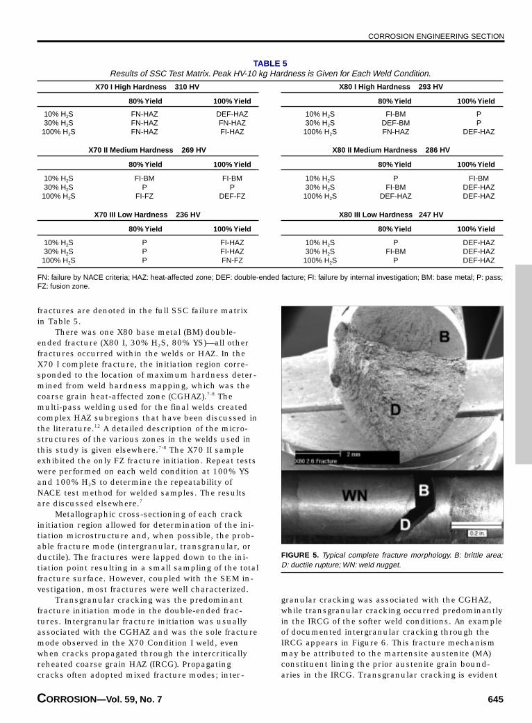
Double-Ended Fracture — All samples that frac-tured into two parts (double-ended fracture) exhib-ited the same general cracking morphology, which isshown in Figure 5. A surface-initiated thumbnailcrack propagated by a brittle fracture mode (B) per-pendicular to the applied stress until it reached acritical size. Ductile (D) rupture characterized by aductile dimple fracture surface then occurred, usu-ally at 45° to the tensile axis. This general fracturemorphology was exhibited regardless of whetherfracture initiated in the base metal (BM), fusion zone(FZ), or heat-affected zone (HAZ). In fractures thatinitiated in the FZ or a HAZ region, final ductile rup-ture always occurred in the FZ.
Post-fracture exposure of the fracture surfaceto the corrosive solution caused the formation of aniron sulfide corrosion product in most cases, makingdetermination of fracture mode at times difficultor impossible in the SEM. Some detailed transgranu-lar features were observed in samples that wereremoved shortly after failure. Intergranular crackingfeatures were more easily discerned. The complete
TABLE 4Cathodic Charging Testing Parameters
Sample Solution Applied Stress (% YS) ∆i (µA/cm2) imax (µA/cm2)
X70 I NACE + As 100 50 700X70 II NACE + As 100 50 700X70 III NACE + As 100 25 625X80 III NACE + As 100 25 625X70 I NACE + As 100 25 850X80 III NACE + As 100 25 850X70 I NACE 100 50 625X80 II NACE 100 50 625X70 I NACE + As 100 — 2,000/24 hX80 II NACE + As 100 — 2,000/24 hX70 I NACE + As 100 — 3,000/24 hX80 II NACE + As 100 — 3,000/24 h
CORROSION ENGINEERING SECTION
CORROSION—Vol. 59, No. 7 645
fractures are denoted in the full SSC failure matrixin Table 5.
There was one X80 base metal (BM) double-ended fracture (X80 I, 30% H2S, 80% YS)—all otherfractures occurred within the welds or HAZ. In theX70 I complete fracture, the initiation region corre-sponded to the location of maximum hardness deter-mined from weld hardness mapping, which was thecoarse grain heat-affected zone (CGHAZ).7-8 Themulti-pass welding used for the final welds createdcomplex HAZ subregions that have been discussed inthe literature.12 A detailed description of the micro-structures of the various zones in the welds used inthis study is given elsewhere.7-8 The X70 II sampleexhibited the only FZ fracture initiation. Repeat testswere performed on each weld condition at 100% YSand 100% H2S to determine the repeatability ofNACE test method for welded samples. The resultsare discussed elsewhere.7
Metallographic cross-sectioning of each crackinitiation region allowed for determination of the ini-tiation microstructure and, when possible, the prob-able fracture mode (intergranular, transgranular, orductile). The fractures were lapped down to the ini-tiation point resulting in a small sampling of the totalfracture surface. However, coupled with the SEM in-vestigation, most fractures were well characterized.
Transgranular cracking was the predominantfracture initiation mode in the double-ended frac-tures. Intergranular fracture initiation was usuallyassociated with the CGHAZ and was the sole fracturemode observed in the X70 Condition I weld, evenwhen cracks propagated through the intercriticallyreheated coarse grain HAZ (IRCG). Propagatingcracks often adopted mixed fracture modes; inter-
granular cracking was associated with the CGHAZ,while transgranular cracking occurred predominantlyin the IRCG of the softer weld conditions. An exampleof documented intergranular cracking through theIRCG appears in Figure 6. This fracture mechanismmay be attributed to the martensite austenite (MA)constituent lining the prior austenite grain bound-aries in the IRCG. Transgranular cracking is evident
FIGURE 5. Typical complete fracture morphology. B: brittle area;D: ductile rupture; WN: weld nugget.
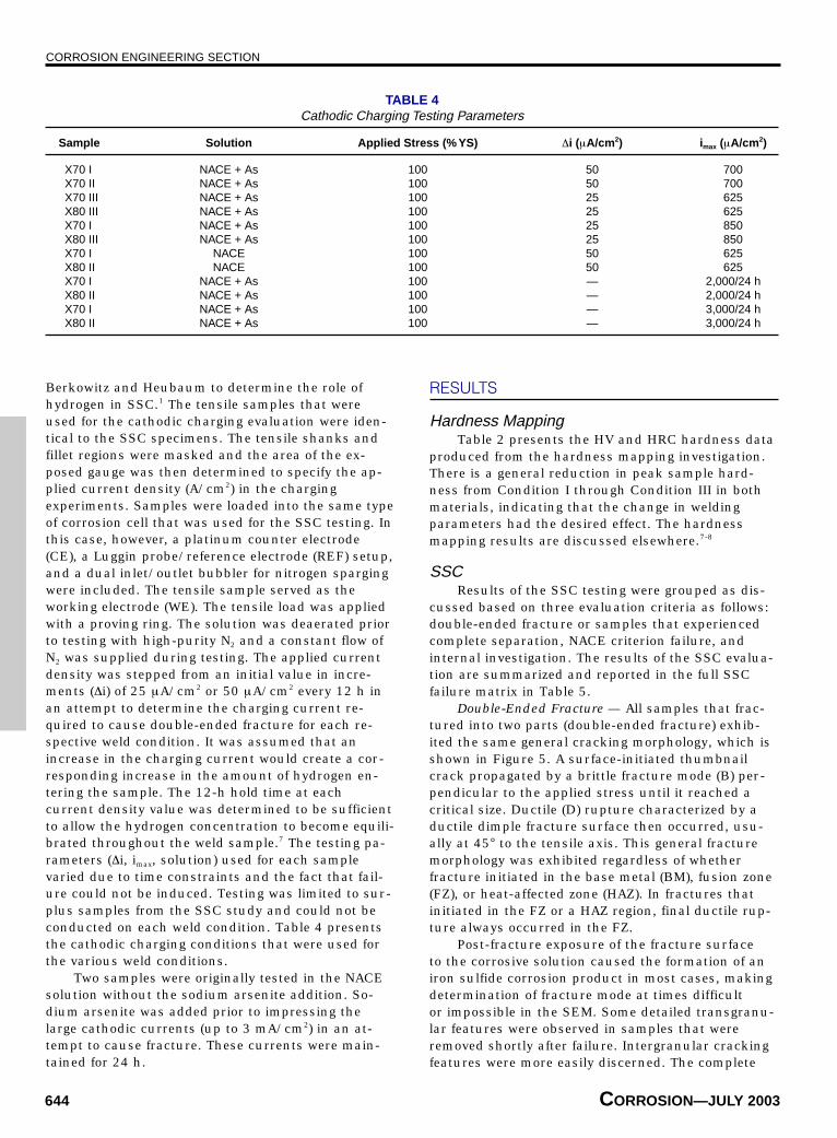
TABLE 5Results of SSC Test Matrix. Peak HV-10 kg Hardness is Given for Each Weld Condition.
10% H2S FN-HAZ DEF-HAZ 10% H2S FI-BM P30% H2S FN-HAZ FN-HAZ 30% H2S DEF-BM P
100% H2S FN-HAZ FI-HAZ 100% H2S FN-HAZ DEF-HAZ
10% H2S FI-BM FI-BM 10% H2S P FI-BM30% H2S P P 30% H2S FI-BM DEF-HAZ
100% H2S FI-FZ DEF-FZ 100% H2S DEF-HAZ DEF-HAZ
10% H2S P FI-HAZ 10% H2S P DEF-HAZ30% H2S P FI-HAZ 30% H2S FI-BM DEF-HAZ
100% H2S P FN-FZ 100% H2S P DEF-HAZ
FN: failure by NACE criteria; HAZ: heat-affected zone; DEF: double-ended facture; FI: failure by internal investigation; BM: base metal; P: pass;FZ: fusion zone.
80% Yield 100% Yield 80% Yield 100% Yield
X70 I High Hardness 310 HV
80% Yield 100% Yield 80% Yield 100% Yield
80% Yield 100% Yield 80% Yield 100% Yield
X70 II Medium Hardness 269 HV X80 II Medium Hardness 286 HV
X70 III Low Hardness 236 HV X80 III Low Hardness 247 HV
X80 I High Hardness 293 HV
CORROSION ENGINEERING SECTION
646 CORROSION—JULY 2003
along the crack path through upper bainite (UB)shown in Figure 7. The most severe X70 II test condi-tion (100% YS, 100% H2S) produced crack initiationin the fusion zone (FZ) and propagation along thefusion boundary.
Crack initiation regions varied between theCGHAZ and IRCG in the X80 Condition I and IIwelds. Cracking initiated in the IRCG in all X80 IIIwelds and propagation also occurred through thisweld region. The most severe test (100% YS, 100%H2S) conditions produced brittle crack propagationthrough the fusion zone in the X80 I and II welds. FZcrack propagation adopted an intergranular morphol-ogy in the FZ coarse grain HAZ (FZCG). Completefracture in the weld was caused only by an appliedstress equivalent to 100% of the specified parent ma-terial minimum yield strength for all weld conditions.The X80 welds were much more susceptible to com-
plete failure, as they constituted a majority of thedouble-ended fractures.
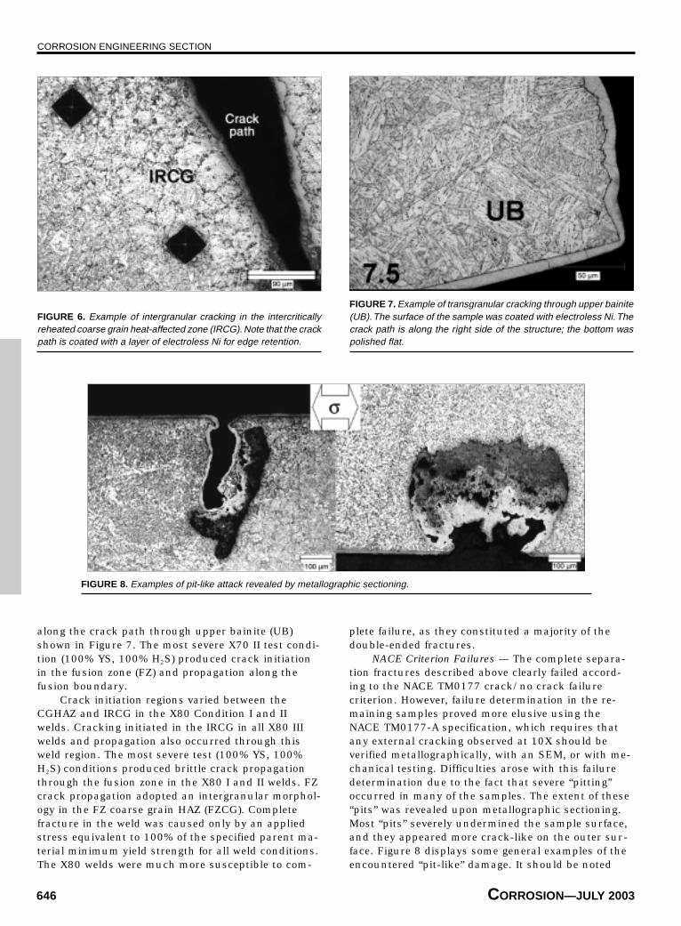
NACE Criterion Failures — The complete separa-tion fractures described above clearly failed accord-ing to the NACE TM0177 crack/no crack failurecriterion. However, failure determination in the re-maining samples proved more elusive using theNACE TM0177-A specification, which requires thatany external cracking observed at 10X should beverified metallographically, with an SEM, or with me-chanical testing. Difficulties arose with this failuredetermination due to the fact that severe “pitting”occurred in many of the samples. The extent of these“pits” was revealed upon metallographic sectioning.Most “pits” severely undermined the sample surface,and they appeared more crack-like on the outer sur-face. Figure 8 displays some general examples of theencountered “pit-like” damage. It should be noted
FIGURE 6. Example of intergranular cracking in the intercriticallyreheated coarse grain heat-affected zone (IRCG). Note that the crackpath is coated with a layer of electroless Ni for edge retention.
FIGURE 7. Example of transgranular cracking through upper bainite(UB). The surface of the sample was coated with electroless Ni. Thecrack path is along the right side of the structure; the bottom waspolished flat.
FIGURE 8. Examples of pit-like attack revealed by metallographic sectioning.
CORROSION ENGINEERING SECTION
CORROSION—Vol. 59, No. 7 647
that the standard usage of the term “pitting” refers tothe localized breakdown of a thin protective passivefilm. Such films do not form on carbon steels at lowpotentials in acidic sour environments. The observedattack might be better described as localized generalcorrosion that occurs at a break in the somewhatprotective iron sulfide film. Nonetheless, the term“pitting” was used.
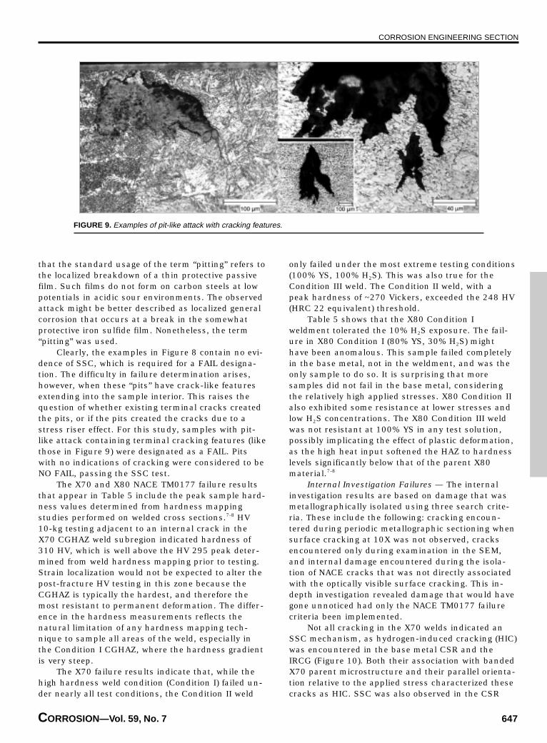
Clearly, the examples in Figure 8 contain no evi-dence of SSC, which is required for a FAIL designa-tion. The difficulty in failure determination arises,however, when these “pits” have crack-like featuresextending into the sample interior. This raises thequestion of whether existing terminal cracks createdthe pits, or if the pits created the cracks due to astress riser effect. For this study, samples with pit-like attack containing terminal cracking features (likethose in Figure 9) were designated as a FAIL. Pitswith no indications of cracking were considered to beNO FAIL, passing the SSC test.
The X70 and X80 NACE TM0177 failure resultsthat appear in Table 5 include the peak sample hard-ness values determined from hardness mappingstudies performed on welded cross sections.7-8 HV10-kg testing adjacent to an internal crack in theX70 CGHAZ weld subregion indicated hardness of310 HV, which is well above the HV 295 peak deter-mined from weld hardness mapping prior to testing.Strain localization would not be expected to alter thepost-fracture HV testing in this zone because theCGHAZ is typically the hardest, and therefore themost resistant to permanent deformation. The differ-ence in the hardness measurements reflects thenatural limitation of any hardness mapping tech-nique to sample all areas of the weld, especially inthe Condition I CGHAZ, where the hardness gradientis very steep.
The X70 failure results indicate that, while thehigh hardness weld condition (Condition I) failed un-der nearly all test conditions, the Condition II weld
only failed under the most extreme testing conditions(100% YS, 100% H2S). This was also true for theCondition III weld. The Condition II weld, with apeak hardness of ~270 Vickers, exceeded the 248 HV(HRC 22 equivalent) threshold.
Table 5 shows that the X80 Condition Iweldment tolerated the 10% H2S exposure. The fail-ure in X80 Condition I (80% YS, 30% H2S) mighthave been anomalous. This sample failed completelyin the base metal, not in the weldment, and was theonly sample to do so. It is surprising that moresamples did not fail in the base metal, consideringthe relatively high applied stresses. X80 Condition IIalso exhibited some resistance at lower stresses andlow H2S concentrations. The X80 Condition III weldwas not resistant at 100% YS in any test solution,possibly implicating the effect of plastic deformation,as the high heat input softened the HAZ to hardnesslevels significantly below that of the parent X80material.7-8
Internal Investigation Failures — The internalinvestigation results are based on damage that wasmetallographically isolated using three search crite-ria. These include the following: cracking encoun-tered during periodic metallographic sectioning whensurface cracking at 10X was not observed, cracksencountered only during examination in the SEM,and internal damage encountered during the isola-tion of NACE cracks that was not directly associatedwith the optically visible surface cracking. This in-depth investigation revealed damage that would havegone unnoticed had only the NACE TM0177 failurecriteria been implemented.
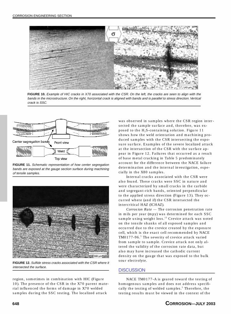
Not all cracking in the X70 welds indicated anSSC mechanism, as hydrogen-induced cracking (HIC)was encountered in the base metal CSR and theIRCG (Figure 10). Both their association with bandedX70 parent microstructure and their parallel orienta-tion relative to the applied stress characterized thesecracks as HIC. SSC was also observed in the CSR
FIGURE 9. Examples of pit-like attack with cracking features.
CORROSION ENGINEERING SECTION
648 CORROSION—JULY 2003
region, sometimes in combination with HIC (Figure10). The presence of the CSR in the X70 parent mate-rial influenced the forms of damage in X70 weldedsamples during the SSC testing. The localized attack
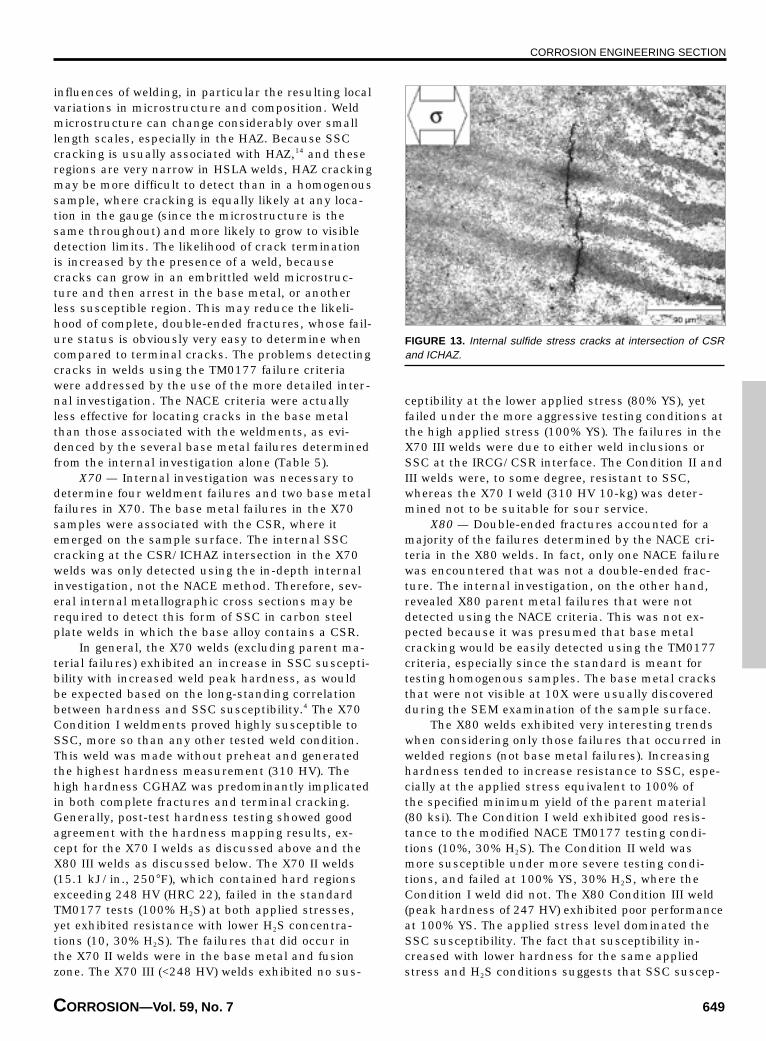
was observed in samples where the CSR region inter-sected the sample surface and, therefore, was ex-posed to the H2S-containing solution. Figure 11shows how the weld orientation and machining pro-duced samples with the CSR intersecting the expo-sure surface. Examples of the severe localized attackat the intersection of the CSR with the surface ap-pear in Figure 12. Failures that occurred as a resultof base metal cracking in Table 5 predominatelyaccount for the difference between the NACE failuredetermination and the internal investigation, espe-cially in the X80 samples.
Internal cracks associated with the CSR werealso found. These cracks were SSC in nature andwere characterized by small cracks in the carbideand segregant-rich bands, oriented perpendicularto the applied stress direction (Figure 13). They oc-curred where (and if) the CSR intersected theintercritical HAZ (ICHAZ).
Corrosion Rate — The corrosion penetration ratein mils per year (mpy) was determined for each SSCsample using weight loss.13 Crevice attack was notedon the tensile shanks of all exposed samples andoccurred due to the crevice created by the exposurecell, which is the exact cell recommended by NACETM0177-96.5 The severity of crevice attack variedfrom sample to sample. Crevice attack not only al-tered the validity of the corrosion rate data, butalso may have increased the cathodic currentdensity on the gauge that was exposed to the bulksour electrolyte.
DISCUSSION
NACE TM0177-A is geared toward the testing ofhomogenous samples and does not address specifi-cally the testing of welded samples.5 Therefore, thetesting results must be viewed in the context of the
FIGURE 10. Example of HIC cracks in X70 associated with the CSR. On the left, the cracks are seen to align with thebands in the microstructure. On the right, horizontal crack is aligned with bands and is parallel to stress direction. Verticalcrack is SSC.
FIGURE 12. Sulfide stress cracks associated with the CSR where itintersected the surface.
FIGURE 11. Schematic representation of how center segregationbands are exposed at the gauge section surface during machiningof tensile samples.
CORROSION ENGINEERING SECTION
CORROSION—Vol. 59, No. 7 649
influences of welding, in particular the resulting localvariations in microstructure and composition. Weldmicrostructure can change considerably over smalllength scales, especially in the HAZ. Because SSCcracking is usually associated with HAZ,14 and theseregions are very narrow in HSLA welds, HAZ crackingmay be more difficult to detect than in a homogenoussample, where cracking is equally likely at any loca-tion in the gauge (since the microstructure is thesame throughout) and more likely to grow to visibledetection limits. The likelihood of crack terminationis increased by the presence of a weld, becausecracks can grow in an embrittled weld microstruc-ture and then arrest in the base metal, or anotherless susceptible region. This may reduce the likeli-hood of complete, double-ended fractures, whose fail-ure status is obviously very easy to determine whencompared to terminal cracks. The problems detectingcracks in welds using the TM0177 failure criteriawere addressed by the use of the more detailed inter-nal investigation. The NACE criteria were actuallyless effective for locating cracks in the base metalthan those associated with the weldments, as evi-denced by the several base metal failures determinedfrom the internal investigation alone (Table 5).
X70 — Internal investigation was necessary todetermine four weldment failures and two base metalfailures in X70. The base metal failures in the X70samples were associated with the CSR, where itemerged on the sample surface. The internal SSCcracking at the CSR/ICHAZ intersection in the X70welds was only detected using the in-depth internalinvestigation, not the NACE method. Therefore, sev-eral internal metallographic cross sections may berequired to detect this form of SSC in carbon steelplate welds in which the base alloy contains a CSR.
In general, the X70 welds (excluding parent ma-terial failures) exhibited an increase in SSC suscepti-bility with increased weld peak hardness, as wouldbe expected based on the long-standing correlationbetween hardness and SSC susceptibility.4 The X70Condition I weldments proved highly susceptible toSSC, more so than any other tested weld condition.This weld was made without preheat and generatedthe highest hardness measurement (310 HV). Thehigh hardness CGHAZ was predominantly implicatedin both complete fractures and terminal cracking.Generally, post-test hardness testing showed goodagreement with the hardness mapping results, ex-cept for the X70 I welds as discussed above and theX80 III welds as discussed below. The X70 II welds(15.1 kJ/in., 250°F), which contained hard regionsexceeding 248 HV (HRC 22), failed in the standardTM0177 tests (100% H2S) at both applied stresses,yet exhibited resistance with lower H2S concentra-tions (10, 30% H2S). The failures that did occur inthe X70 II welds were in the base metal and fusionzone. The X70 III (<248 HV) welds exhibited no sus-
ceptibility at the lower applied stress (80% YS), yetfailed under the more aggressive testing conditions atthe high applied stress (100% YS). The failures in theX70 III welds were due to either weld inclusions orSSC at the IRCG/CSR interface. The Condition II andIII welds were, to some degree, resistant to SSC,whereas the X70 I weld (310 HV 10-kg) was deter-mined not to be suitable for sour service.
X80 — Double-ended fractures accounted for amajority of the failures determined by the NACE cri-teria in the X80 welds. In fact, only one NACE failurewas encountered that was not a double-ended frac-ture. The internal investigation, on the other hand,revealed X80 parent metal failures that were notdetected using the NACE criteria. This was not ex-pected because it was presumed that base metalcracking would be easily detected using the TM0177criteria, especially since the standard is meant fortesting homogenous samples. The base metal cracksthat were not visible at 10X were usually discoveredduring the SEM examination of the sample surface.
The X80 welds exhibited very interesting trendswhen considering only those failures that occurred inwelded regions (not base metal failures). Increasinghardness tended to increase resistance to SSC, espe-cially at the applied stress equivalent to 100% ofthe specified minimum yield of the parent material(80 ksi). The Condition I weld exhibited good resis-tance to the modified NACE TM0177 testing condi-tions (10%, 30% H2S). The Condition II weld wasmore susceptible under more severe testing condi-tions, and failed at 100% YS, 30% H2S, where theCondition I weld did not. The X80 Condition III weld(peak hardness of 247 HV) exhibited poor performanceat 100% YS. The applied stress level dominated theSSC susceptibility. The fact that susceptibility in-creased with lower hardness for the same appliedstress and H2S conditions suggests that SSC suscep-
FIGURE 13. Internal sulfide stress cracks at intersection of CSRand ICHAZ.
CORROSION ENGINEERING SECTION
650 CORROSION—JULY 2003
tibility for the X80 welds might be controlled bylocalized ICHAZ and intercritically reheated (IRHAZ)softening, which was observed in the hardnessmapping.7-8
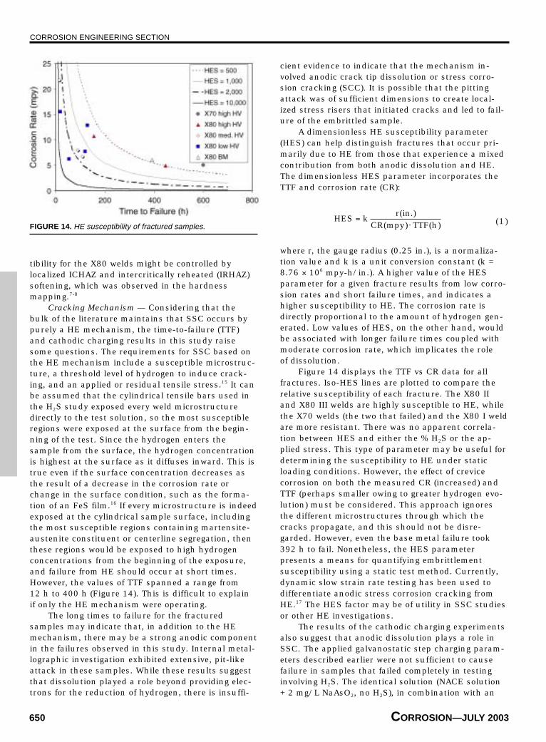
Cracking Mechanism — Considering that thebulk of the literature maintains that SSC occurs bypurely a HE mechanism, the time-to-failure (TTF)and cathodic charging results in this study raisesome questions. The requirements for SSC based onthe HE mechanism include a susceptible microstruc-ture, a threshold level of hydrogen to induce crack-ing, and an applied or residual tensile stress.15 It canbe assumed that the cylindrical tensile bars used inthe H2S study exposed every weld microstructuredirectly to the test solution, so the most susceptibleregions were exposed at the surface from the begin-ning of the test. Since the hydrogen enters thesample from the surface, the hydrogen concentrationis highest at the surface as it diffuses inward. This istrue even if the surface concentration decreases asthe result of a decrease in the corrosion rate orchange in the surface condition, such as the forma-tion of an FeS film.16 If every microstructure is indeedexposed at the cylindrical sample surface, includingthe most susceptible regions containing martensite-austenite constituent or centerline segregation, thenthese regions would be exposed to high hydrogenconcentrations from the beginning of the exposure,and failure from HE should occur at short times.However, the values of TTF spanned a range from12 h to 400 h (Figure 14). This is difficult to explainif only the HE mechanism were operating.
The long times to failure for the fracturedsamples may indicate that, in addition to the HEmechanism, there may be a strong anodic componentin the failures observed in this study. Internal metal-lographic investigation exhibited extensive, pit-likeattack in these samples. While these results suggestthat dissolution played a role beyond providing elec-trons for the reduction of hydrogen, there is insuffi-
cient evidence to indicate that the mechanism in-volved anodic crack tip dissolution or stress corro-sion cracking (SCC). It is possible that the pittingattack was of sufficient dimensions to create local-ized stress risers that initiated cracks and led to fail-ure of the embrittled sample.
A dimensionless HE susceptibility parameter(HES) can help distinguish fractures that occur pri-marily due to HE from those that experience a mixedcontribution from both anodic dissolution and HE.The dimensionless HES parameter incorporates theTTF and corrosion rate (CR):
HES kr in
CR mpy TTF h=
⋅( .)
( ) ( ) (1)
where r, the gauge radius (0.25 in.), is a normaliza-tion value and k is a unit conversion constant (k =8.76 × 10⁶ mpy-h/in.). A higher value of the HESparameter for a given fracture results from low corro-sion rates and short failure times, and indicates ahigher susceptibility to HE. The corrosion rate isdirectly proportional to the amount of hydrogen gen-erated. Low values of HES, on the other hand, wouldbe associated with longer failure times coupled withmoderate corrosion rate, which implicates the roleof dissolution.
Figure 14 displays the TTF vs CR data for allfractures. Iso-HES lines are plotted to compare therelative susceptibility of each fracture. The X80 IIand X80 III welds are highly susceptible to HE, whilethe X70 welds (the two that failed) and the X80 I weldare more resistant. There was no apparent correla-tion between HES and either the % H2S or the ap-plied stress. This type of parameter may be useful fordetermining the susceptibility to HE under staticloading conditions. However, the effect of crevicecorrosion on both the measured CR (increased) andTTF (perhaps smaller owing to greater hydrogen evo-lution) must be considered. This approach ignoresthe different microstructures through which thecracks propagate, and this should not be disre-garded. However, even the base metal failure took392 h to fail. Nonetheless, the HES parameterpresents a means for quantifying embrittlementsusceptibility using a static test method. Currently,dynamic slow strain rate testing has been used todifferentiate anodic stress corrosion cracking fromHE.17 The HES factor may be of utility in SSC studiesor other HE investigations.
The results of the cathodic charging experimentsalso suggest that anodic dissolution plays a role inSSC. The applied galvanostatic step charging param-eters described earlier were not sufficient to causefailure in samples that failed completely in testinginvolving H2S. The identical solution (NACE solution+ 2 mg/L NaAsO2, no H2S), in combination with an
FIGURE 14. HE susceptibility of fractured samples.
CORROSION ENGINEERING SECTION
CORROSION—Vol. 59, No. 7 651
impressed current of –140 µA/cm2, created a steady-state hydrogen permeation flux equivalent to thatproduced at open circuit with the standard H2S solu-tion in a steel tested by Berkowitz and Heubaum.1 Allexperimental cathodic currents eventually exceededthis current density, going to at least –625 µA/cm2.
The hold time was even extended to 24 h for thehighest applied currents. However, the cathodicallycharged samples did not fail. If the SSC mechanismrelied solely on the concentration of absorbed hydro-gen in the double-ended fractures, then the severehydrogen charging conditions should have been suf-ficient to reproduce these failures. The impressedcathodic currents effectively eliminated anodic disso-lution (especially at higher applied currents) and anypossible anodic contribution to the cracking mecha-nism. Apparently, dynamic straining is required toembrittle cathodically charged samples, but staticstress is sufficient in sour environments.
Extrapolation to Service — Due to the physicalconstraints that prevented the actual untemperedcap passes from being isolated in the gauge sectionsof the tested tensile samples, it may not be prudentto extrapolate data from this study to in-service weldcap regions. This is particularly true for the X70Condition I welds, which exhibited significant tem-pering responses as evidenced by the considerablylower peak sample hardness (310 HV) relative to thepeak weld hardness (336 HV). Regardless, the X70Condition I welds did not pass any SSC test, whenconsidering both failure criteria. The use of the lowheat input (15.1 kJ/in.) without preheat is not sug-gested for the X70 material in sour service. The X80Condition I weld exhibited considerably lower tem-pering responses, such that the machined samplecontained hardness similar to the hardest weld capregions (only 2 HV difference). This weld conditionexhibited base metal anomalous failures at 80% YS,but not at 100% YS (Table 5). The reason this oc-curred is unclear, because samples that failed at80% YS would be expected to fail at even higherapplied stresses.
Heeding the failures determined according to theNACE criteria and internal investigation, yet ignoringthe base metal failures, both the X80 Condition I andX70 Condition II welds were resistant to SSC in the10% and 30% H2S solutions. Additionally, the X80Condition II weld was resistant in only the 10% H2Ssolution. The base metal failures in the X70 I and IIwelds were attributed to surface emergence of theCSR. This region would not be directly exposed to theservice environment in a welded service pipe.
Assuming that the reduction in the dissolved H2Sin the NACE solution produces a corresponding re-duction in the absorbed hydrogen content in the SSCtest samples, it may be possible to predict the loca-tions in an in-service pipe wall where elevated hard-ness (>HV 248) can be tolerated. Asahi, et al.,
determined a correlation between the absorbed con-centration of hydrogen, CH, solution pH, and the con-centration of H2S in solution to quantify the severityof a particular sour environment:18
C K H H SH = ⋅+( ) .2
0 26 (2)
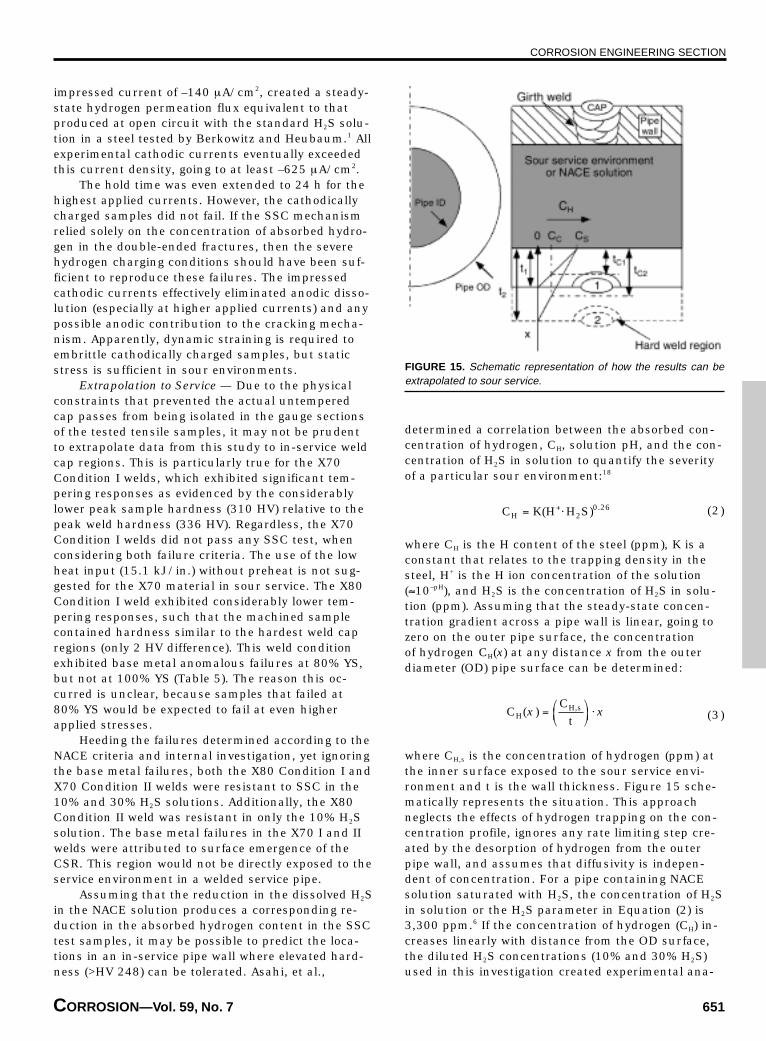
where CH is the H content of the steel (ppm), K is aconstant that relates to the trapping density in thesteel, H+ is the H ion concentration of the solution(≈10–pH), and H2S is the concentration of H2S in solu-tion (ppm). Assuming that the steady-state concen-tration gradient across a pipe wall is linear, going tozero on the outer pipe surface, the concentrationof hydrogen CH(x) at any distance x from the outerdiameter (OD) pipe surface can be determined:
CC
tHH s( ) ,x x=
⋅ (3)
where CH,s is the concentration of hydrogen (ppm) atthe inner surface exposed to the sour service envi-ronment and t is the wall thickness. Figure 15 sche-matically represents the situation. This approachneglects the effects of hydrogen trapping on the con-centration profile, ignores any rate limiting step cre-ated by the desorption of hydrogen from the outerpipe wall, and assumes that diffusivity is indepen-dent of concentration. For a pipe containing NACEsolution saturated with H2S, the concentration of H2Sin solution or the H2S parameter in Equation (2) is3,300 ppm.6 If the concentration of hydrogen (CH) in-creases linearly with distance from the OD surface,the diluted H2S concentrations (10% and 30% H2S)used in this investigation created experimental ana-
FIGURE 15. Schematic representation of how the results can beextrapolated to sour service.
CORROSION ENGINEERING SECTION
652 CORROSION—JULY 2003
logs to two different x positions within the pipe wall.To determine the value of x at which the SSC-resis-tant welds would be tolerated in terms of the pipewall thickness, t, Equation (2) is substituted for bothCH(x) and CH,s in Equation (3), which is then rear-ranged to solve for x:
x x x
.
=
⋅ =
⋅
( )( )
( ),
.H SH S
tH S
ppmt
s
2
2
0 26
2
0 26
3 300 (4)
The term (H2S)x in the numerator is a variable thatrelates to the absorbed hydrogen concentration cre-ated by either of the diluted test solutions and corre-sponds to the concentration at a specific location inthe full-scale pipe wall. The term in the denominator,(H2S)s = 3,300 ppm, is the absorbed hydrogen con-centration created at the inner pipe surface in con-tact with the process stream containing saturatedH2S. The H+ factor drops out because the pH is iden-tical in both the NACE solution and the hypotheticalprocess stream.
If the concentration of H2S (ppm) in one of thetests in this study for which a sample received apassing indication is inputted for the (H2S)x value inEquation (4), then the resulting value of x can beused to determine the depth from the OD that thegiven microstructure with a given hardness could beexpected to survive if the inside of the pipe were ex-posed to a 100% H2S environment. For example, the269 HV peak hardness in the X70 II samples thatpassed the 10% H2S exposure (H2S = 330 ppm) couldbe tolerated up to 0.55t in from the OD. Samplespassing the 30% H2S exposure (H2S = 990 ppm) indi-cate that the peak weld hardness could be toleratedup to 0.73t in from the OD. Samples that passedthe NACE TM0177 standard exposure (100% H2S =3,300 ppm), like the X70 and X80 Condition III weldsat 80% YS, could tolerate direct contact with thesolution in a full-scale test, if the residual stressesare not excessive.
The complex interactions among microstructure,corrosion, HE, and mechanical stress states makealmost any experimental investigation of SSC inweldments very complicated. The simplified approachadopted by this investigation has several possiblesources of inherent weakness. Of these, the mostimportant limitations were on the inability of thedogbone tensile samples to isolate actual cap weldregions, the uncharacterized relationship betweenH2S concentration and absorbed hydrogen content,and the duplication of residual weld stresses. In lightof these limitations, and those present in other SSCstudies, care should and must be taken when ex-trapolating laboratory testing results to anticipatedservice performance. The environmental, safety, andmonetary implications of SSC service failures can be,to say the least, enormous.
CONCLUSIONS
❖ The susceptibility to SSC of welded X70 and X80line pipe steel was studied under conditions of vary-ing applied stress, H2S concentration, and peak weldhardness. Several important observations were madein this work.❖ Except for the internal SSC cracks associated withthe CSR/weld intersection, the NACE TM0177 failurecriteria were found to be adequate for detectingweldment cracks in narrow HAZ.❖ A maximum hardness of 248 HV should be main-tained for carbon steel parent materials and regionsof carbon steel weldments that are in direct contactwith sour service environments.❖ A relaxation in the allowable hardness of outer capregions in sour service girth welds is reasonable, asoriginally recommended by TWI, as long as the wallthickness is sufficient and the performance of theas-welded material is characterized with laboratoryscreening.❖ The low-carbon (~0.03 wt% C) X80 steel wassubject to HAZ softening relative to the base metal,which increased SSC susceptibility due to strainlocalization. A minimum HAZ hardness may be justi-fied for these types of steels.❖ The low-carbon (~0.03 wt% C) X80 steel was moreresistant to SSC in the as-welded condition and tol-erated much higher absolute tensile stresses thanthe as-welded X70 steel.❖ SSC experiments showed that the CSR in control-rolled steels is susceptible to SSC, and may dictateboth alloy and weld susceptibility. Cracking in theCSR went unnoticed when applying only the NACEfailure criteria.❖ Cathodic charging results, TTF observations, andan observed localized breakdown in the somewhatprotective iron sulfide film suggest that there is ananodic component to SSC.❖ Laboratory screening may permit the use of steelwelds with regions exceeding 248 HV in sour serviceenvironments, provided these high hardness regionsare not in contact with the sour environment and thelocal residual stresses are well characterized.
ACKNOWLEDGMENTS
This project was funded by an Edison WeldingInstitute Cooperative Research Program, 43564-IRP.The authors acknowledge personal contributionsfrom C. Ribardo (formerly at EWI) and G. Todd (CCTechnologies). CC Technologies donated the use oftheir laboratory facility for H2S testing performed inthis study. The welds were made by Edison WeldingInstitute.
REFERENCES
1. B.J. Berkowitz, F.H. Heubaum, Corrosion 40, 5 (1984): p. 240.
CORROSION ENGINEERING SECTION
CORROSION—Vol. 59, No. 7 653
2. R.D. Kane, Int. Met. Rev. 30, 6 (1985): p. 291.3. J.C. Turn, B.E. Wilde, C.A. Troianos, Corrosion 39, 9 (1983):
p. 364.4. NACE Standard Materials Requirements, “Sulfide Stress Crack-
ing Resistant Metallic Materials for Oilfield Equipment” (Hous-ton, TX: NACE International, 1994), p. 1.
5. NACE Standard Test Method, “Laboratory Testing of Metals forResistance to Specific Forms of Environmental Cracking in H2SEnvironments” (Houston, TX: NACE International, 1996).
6. R.A. Walker, The Significance of Local Hard Zones on the Out-side of Pipeline Girth Welds (Cambridge, U.K.: The Welding In-stitute, 1989), p. 1.
7. G. Omweg, “Sulfide Stress Cracking Resistance of Welded High-Strength Low-Alloy Steels” (MS thesis, Materials Science andEngineering Department, The Ohio State University, 2001).
8. G.M. Omweg, G.S. Frankel, W.A. Bruce, G. Koch, Weld J. 82(2003): p. 136-144S.
9. M.S. Cayard, R.D. Kane, Corrosion 53, 3 (1997): p. 227.10. W.B. Morrison, “Status of Microalloyed (HSLA) Steel Develop-
ment,” eds. J.T. Hickey, D.G. Howden, M.D. Randall, Proc. Int.
Conf. Metall., Weld., Qualif. Microalloyed (HSLA) SteelWeldments (Miami, FL: American Welding Society, 1990).
11. “Sulfide Stress Cracking Resistance of Pipeline Welds,” Mater.Perform. 32, 1 (1993): p. 58-64.
12. D.P. Fairchild, N.V. Bangaru, J.Y. Koo, P.L. Harrison, A.Ozekcin, Weld. Res. 70 (1991): p. 321s.
13. D.A. Jones, Principles and Prevention of Corrosion, 2nd ed.(Upper Saddle River, NJ: Prentice-Hall, 1996), p. 572.
14. R.D. Kane, J.P. Ribble, M.J. Schofield, Weld. J. 70 (1991): p.56.
15. H.H. Tang, M.S. Cayard, “Test Methods for the Evaluation ofMaterials for Wet H2S Service,” CORROSION/99, paper no. 421(Houston, TX: NACE, 1999).
16. S.Y. Tsai, H.C. Shih, Corros. Sci. 38, 5 (1996): p. 705.17. C.D. Kim, B.E. Wilde, “A Review of the Strain-Rate Stress Cor-
rosion Cracking Test,” Stress Corrosion Cracking—The SlowStrain-Rate Technique, in ASTM STP 665, eds. G.M. Ugiansky,J.H. Payer (West Conshohocken, PA: ASTM International,1979), p. 97.
18. H. Asahi, M. Ueno, T. Yonezawa, Corrosion 50, 7 (1994): p. 537.
CORROSION RESEARCH CALENDAR
CORROSION is a technical research journal devoted to furthering the knowledge of corrosion science and engineering. Withinthat context, CORROSION accepts notices of calls for papers and upcoming research grants, meetings, symposia, andconferences. All pertinent information, including the date, time, location, and sponsor of an event should be sent as far inadvance as possible to: Angela Jarrell, Managing Editor, CORROSION, 1440 South Creek Drive, Houston, TX 77084-4906.Notices that are not accompanied by the contributor’s name, daytime telephone number, and complete address will not beconsidered for publication.
2003
July 14-17—RUST 2003, 13th U.S. Navyand Industry Corrosion Technology—Louisville, NY; Contact Don Hileman,E-mail: [email protected]; Website: http://cte-online.org.
July 15-17—1st InternationalConference on Concrete Repair—St.Malo, Brittany; Contact ConferenceSecretariat, Phone: +44 (0) 208381 1429;E-mail: [email protected].
August 10-14—SeaHorse 2003, TheMarine Corrosion Conference—Wrightsville Beach, NC; Contact LisaWeiss, Phone: 910/256-2271, ext. 300;E-mail: [email protected]; Website: www.marine-corrosion.com.
August 18-20—2003 InternationalMaintenance Conference—Chicago, IL;Contact Brent Lancaster, Phone: 704/547-6017; E-mail: [email protected]; Website: www.epri.com.
August 19-22—7th Corrosion andProtection Congress and 2ndInternational Materials Congress—Bucaramanga, Colombia; Contact DariaPena, Phone: +57 7 6320471; E-mail:[email protected].
August 21-22—Maritime EnvironmentalEngineering Technical Symposium2003—Arlington, VA; Contact HenryWilson, 410/764-6065.
August 28-29—28th Conference on OurWorld in Concrete and Structures—Singapore; Contact ConferenceSecretariat, Phone: +(065) 67332922; E-mail: [email protected]; Web site:www.cipremier.com.
* September 7-11—NACE CorrosionTechnology Week—Pittsburgh, PA;Contact NACE, 281/228-6200.
* September 14-17—NACE Northern AreaEastern Conference—Ottawa, ON,Canada; Contact Bruce Baldock, Phone:613/998-4396; E-mail: [email protected].
September 15-18—The 2nd ASMInternational Surface EngineeringCongress and Exposition—Indian-apolis, IN; Contact ASM CustomerService, Phone: 440/338-5151, dial 6;E-mail: [email protected].
* September 21-24—NACE Eastern AreaConference—Columbus, OH; ContactJeff Didas, Phone: 804/672-2718; E-mail:[email protected].
September 28-October 2—Eurocorr2003—Budapest, Hungary; Contact ErikaKalman, Phone: +36 1 3257548; E-mail:[email protected]; Web site:www.chemres.hu/eurocorr.
* October 5-9—NACE Central AreaConference—Houston, TX; Contact JaneBrown, 713/468-4765.
October 6-8—Water Middle East 2003—Manama, Bahrain; Contact Amy Schur,Phone: 613/549-0404; E-mail:[email protected].
October 13-16—ASM International’sMaterials Solutions Conference andExposition—Pittsburgh, PA; ContactASM Customer Service, Phone: 440/338-5151, dial 6; E-mail: [email protected].
* October 20-24—LATINCORR-2003, 5thNACE Latin American Region CorrosionCongress, 8th Ibero American Congressof Corrosion and Protection—Santiago,Chile; Contact Laura Lillo, E-mail:[email protected]; Web site:www.latincorr.cl.
October 26-30—SSPC AnnualConference—New Orleans, LA; ContactRose Mary Surgent, Phone: 412/281-2331;Fax: 412/281-9993; E-mail: [email protected].
November 11-13—3rd Stainless SteelWorld Conference and Expo,Maastricht, The Netherlands; ContactSjef Roymans, Phone: +31 575 585286;E-mail: [email protected].
November 12-14—ICE 2003–FSCT 81stAnnual Meeting and InternationalCoatings Expo—Blue Bell, PA; ContactMark Moon, Phone: 610/940-0777; E-mail:[email protected].
* Sponsored or cosponsored by NACEInternational.