Embed Size (px)
Citation preview

International Research Journal of Engineering and Technology (IRJET) e-ISSN: 2395-0056
Volume: 02 Issue: 06 | Sep-2015 www.irjet.net p-ISSN: 2395-0072
© 2015, IRJET ISO 9001:2008 Certified Journal Page 457
Performance of PLC controlled pneumatic elevator
Hadeel Safa'a Hussein1, Maher Yahya Salloom 2, Roaa abbas3
1 Hadeel H., Mechatronics Engineering Department, Al-Khwarizmiy College of Engineering, University Of Baghdad, Diyala, Iraq
2Maher S., Mechatronics Engineering Department, Al-Khwarizmiy College of Engineering, University Of Baghdad, Baghdad, Iraq
3 Roaa , Mechatronics Engineering,Technological university, Baghdad, Iraq
---------------------------------------------------------------------***---------------------------------------------------------------------Abstract - An elevator is a type of vertical transport
equipment that efficiently transports people or
commodities between floors (levels, decks) of a
building, silo, or other structure. Elevators are
generally powered by electric motors that drive
traction cables with counterweight systems like a hoist.
Other types of elevators powered using hydraulic
system to raise a hydraulic cylindrical piston. This
paper present a system can be controlled using the
programmable logic controller PLC to implement the
orders of the elevator that are received through the use
of push button switches. This model serves the
educational purpose to learn the student about PLC and
arduino programming as well as the pneumatic circuits
building, the test work of this system in the real world is
to serve the special buildings that didn't have more
than four floors. The performance of pneumatic
elevator is studied. As the results the best parameters
are obtained.
Key Words: pneumatic-elevator, PLC, Electro-
pneumatic
1. Introduction A pneumatic elevator is a machine that relies on air pressure changes to transport passengers up and down to various levels within a building. These machines are much less complex than traditional elevators, which rely on elaborate pulley and cable systems in order to operate. Pneumatic elevators are typically used in residential applications that range from two to four stories such as In houses , small hotels, small communities, shops, and some public commerce such as private clinics, geriatrics , etc due to their compact design because excavating a pit, and rodless cylinder way are not required. The pneumatic elevator is a prototype model that employs the pneumatic, electronic and electrical components see (figure 1). The
elevator can be controlled manually by the external bush buttons or by the smart phone application. The central operating unit consists of a PLC that controls the pneumatic rodless cylinder which carries the elevator car; also control the four valves of pneumatic elevator doors in each floor. The bush buttons that are connected to the PLC gives the signals of calling the car to the appropriate floor.
Fig-1: pneumatic elevator block diagram [1] has suggested the model of pneumatic elevator that is a combines of pneumatic and electrical components, The central operating unit consists of a PLC that controls the air flow rate into central unit (rodless pneumatic cylinder), which carries the car of the elevator controlled by a directional control valve, also four directional control valves controlling the floor doors. [2] Have described the using of Programmable Logic Controller to instruct a four-floor elevator system. Elevator is an appropriate system where we can explore a lot of features of the PLC. The PLC system just makes things easier for the design and maintenance engineer. [3] Developed that Elevator is a perpendicular conveyance which widely used in high layer buildings nowadays? Computer control technology in the lift on a wide range of applications, so that the lift operating efficiency and reliability has been greatly improved, but only through the traditional manual found fault and fault handling methods become increasingly are

International Research Journal of Engineering and Technology (IRJET) e-ISSN: 2395-0056
Volume: 02 Issue: 06 | Sep-2015 www.irjet.net p-ISSN: 2395-0072
© 2015, IRJET ISO 9001:2008 Certified Journal Page 458
not suited, and the efficiency is low. [4] Mentioned that the car parking is a big issue which in turn causes traffic jam problem. To overcome this problem, “Automatic Multistoried Car Parking System” is best solution. The system is based on PLC and pneumatic system operates. There is facility of lift to carry the car to up and down. In this system human power is not used therefore error is less also required low space with provides highest security and greatest flexibility. [5] Automation is a technology to control the particular process in order to increase reliability and efficiency by means of programmed commands combined with automatic feedback control. PLCs now have a much longer service life. Therefore, little maintenance is required. Almost in any production line, machine function or process can be automated using a PLC. The objective of the work is to study the performance of pneumatic elevator that controlled PLC.
2. Pneumatic systems The reason for using pneumatics, or any other type of energy transmission on a machine, is to perform work. The accomplishment of work requires the application of kinetic energy to a resisting object resulting in the object moving through a distance. In a pneumatic system, energy is stored in a potential state under the condition of compressed air. The air distribution system is sized to carry the required air flow with minimum friction losses through parts of pipe and various fittings. The compressor pumps air from the atmosphere into the receiver, reducing its volume and raising its pressure level. [6]
2.1 Pneumatic cylinder Pneumatic cylinders (sometimes known as air cylinders) are mechanical devices which use the power of compressed gas to produce a force in a reciprocating linear motion. Like hydraulic cylinders, something forces a piston to move in the desired direction. The piston is a disc or cylinder, and the piston rod transfers the force it develops to the object to be moved. Engineers sometimes prefer to use pneumatics because they are quieter, cleaner, and do not require large amounts of space for fluid storage. [7]
2.2 Rodless Band Cylinders Like the rodless magnetically coupled cylinders, the band cylinder saves space by using a carriage that is coupled to the piston and rides over the body of the cylinder. In this case the piston is rigidly coupled to the carriage, and rides inside the bore of the body extrusion. As the piston moves, it opens and closes a seal at the top of the cylinder. The seal works like a zipper, minimizing leakage. Compared to
magnetically coupled cylinders, band types leak more, but are not subject to decoupling. [8]
2.3 Directional control valve Control valves are valves used to control conditions such as flow, pressure, temperature, and liquid level by fully or partially opening or closing in response to signals received from controllers that compare a "set point" to a "process variable" whose value is provided by sensors that monitor changes in such conditions. Control Valve is also termed as the Final Control Element. [9]
3. Programmable logic controller The programmable logic controller (PLC) is basically a digital computer designed for use in machine control. Unlike a personal computer, it has been designed to operate in the industrial environment and is equipped with special input/output interfaces and a control programming language. A PLC is an example of a real-time system since the output of the system controlled by the PLC depends on the input conditions. [10] More recently electricity has been used for control and early electrical control was based on relays. These relays allow power to be switched on and off without a mechanical switch. It is common to use relays to make simple logical control decisions. The development of low cost computer has brought the most recent revolution, the Programmable Logic Controller (PLC). PLCs have been gaining popularity on the factory floor and will probably remain predominant for some time to come. Most of this is because of the advantages they offer. • Cost effective for controlling complex systems. • Flexible and can be reapplied to control other systems quickly and easily. • Computational abilities allow more sophisticated control. • Trouble shooting aids make programming easier and reduce downtime. • Reliable components make these likely to operate for years before failure. [11]
4. Construction The construction designed in Automation studio software 5.2 as electrical circuit connecting PLC and pneumatic circuit to operate in simulation see (figure 2). The structure of the model was made of aluminous, whereas the basic proportions come from the chosen such as the pneumatic rodless cylinder that carrying the elevator car from top to bottom and vice versa as a part of this structure. The front side is separated into four floors by aluminous profiles that carry the door pistons. Highs carrying the elevator door are fasten to the right side of the frame. The door is filled by black boards of polymer; the rest sides are properly modified and made from black boards of polymer. The elevator car are made the same as the structure form and directly attached to the rodless

International Research Journal of Engineering and Technology (IRJET) e-ISSN: 2395-0056
Volume: 02 Issue: 06 | Sep-2015 www.irjet.net p-ISSN: 2395-0072
© 2015, IRJET ISO 9001:2008 Certified Journal Page 459
cylinder. Electrical and pneumatic circuits are subjected to a fixed board inside the elevator. The PLC used for this elevator is an industrial Mitsubishi type MELSEC FX2N-48MR that receive project requirements, consist of 27 I/Ps and 27O/Ps almost of them used to accomplish the connections of the sensors on the inputs of PLC and the valves terminals on the outputs of the PLC, (figure 3) shows the MITSUBISHI PLC that has been used in this work.
Fig-2: pneumatic circuit by automation studio 5.2
Fig-3: programmable logic controller PLC
5. Control of pneumatic components The regulation of air piped from the compressor ensures the regulation set. This set is composed of (air filter, air lubricator, pressure regulator) and placed at the compressor stage outside the elevator. The PLC connected to the valve terminals that contain 5/2 way valves, where each of them controls the motion of the piston carrying the floor door of the elevator model, 5/3 way valve is also connected to the PLC to control the motion of rodless cylinder see (figure 4) all of these valves are connected to the o/p PLC stage see (figure 5). Motion of these door floor pistons and the rodless piston is attached by the limit switches contacts that connected to the PLC I/p stage. The PLC is programmed by ladder language using special software of the Mitsubishi PLC type (Gx developer), outside control buttons are also connected to the PLC to control the elevator motion that are placed at the front side elevator board.
Fig-4: elevator car and doors

International Research Journal of Engineering and Technology (IRJET) e-ISSN: 2395-0056
Volume: 02 Issue: 06 | Sep-2015 www.irjet.net p-ISSN: 2395-0072
© 2015, IRJET ISO 9001:2008 Certified Journal Page 460
Fig-5: pneumatic and electrical circuit
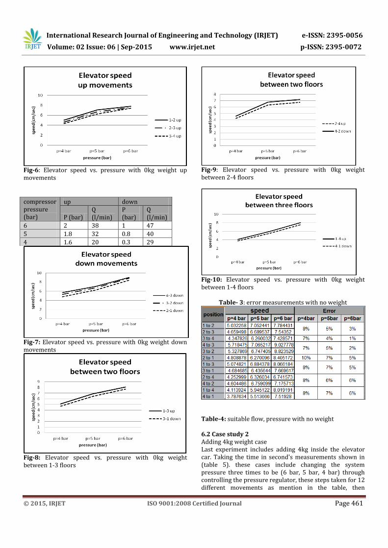
6. Results 6.1 Case study 1 Starting by the first case that done without adding any weight inside the elevator car, taking the time in seconds measurements shown in (table 1). these cases include changing the system pressure three times to be (6 bar, 5 bar, 4 bar) through controlling the pressure regulator, these steps taken for 12 different movements as mention in the table, then measuring the speed for the same cases shown in (table 2). To make the results more obvious its viewed in graphical shape, (figure 6) shows the elevator speed vs. pressure with 0kg weight up movements, (figure 7) shows the elevator speed vs. pressure with 0kg weight down movements, (figure 8) shows the elevator speed vs. pressure with 0kg weight between 1-3 floors, (figure 9) shows the elevator speed vs. pressure with 0kg weight between 2-4 floors, (figure 10) shows the elevator speed vs. pressure with 0kg weight between 1-4 floors. The next measurements were about the percentage error between each two case as shown in (table 3). Then taking the best reading of flow, pressure for up and down movements in this weight case, see (table 4).
Table-1: time measurements with no weight
position time (sec)
pr=6bar pr=5bar pr=4bar
1 to 2 5.01 5.53 7.75
2 to 3 5.17 5.83 8.37
3 to 4 5.25 6.23 8.97
4 to 3 4.32 5.52 6.82
3 to 2 4.42 5.78 7.12
2 to 1 4.64 6.22 8.11
1 to 3 9.67 11.54 15.37
3 to 1 10.17 12.12 16.65
2 to 4 11.57 12.33 18.34
4 to 2 10.87 11.54 16.94
1 to 4 14.59 19.68 28.44
4 to 1 15.56 21.22 30.89
Table-2: speed measurements with no weight
position speed
p=4 bar p=5 bar p=6 bar
1 to 2 5.032258 7.052441 7.784431
2 to 3 4.659498 6.689537 7.54352
3 to 4 4.347826 6.260032 7.428571
4 to 3 5.718475 7.065217 9.027778
3 to 2 5.327869 6.747405 8.823529
2 to 1 4.808878 6.270096 8.405172
1 to 3 5.074821 6.884378 8.066184
3 to 1 4.684685 6.435644 7.669617
2 to 4 4.252999 6.326034 6.741573
4 to 2 4.604486 6.759099 7.175713
1 to 4 4.113924 5.945122 8.019191
4 to 1 3.787634 5.513666 7.51928
International Research Journal of Engineering and Technology (IRJET) e-ISSN: 2395-0056
Volume: 02 Issue: 06 | Sep-2015 www.irjet.net p-ISSN: 2395-0072
© 2015, IRJET ISO 9001:2008 Certified Journal Page 461
Fig-6: Elevator speed vs. pressure with 0kg weight up movements
Fig-7: Elevator speed vs. pressure with 0kg weight down movements
Fig-8: Elevator speed vs. pressure with 0kg weight between 1-3 floors
Fig-9: Elevator speed vs. pressure with 0kg weight between 2-4 floors
Fig-10: Elevator speed vs. pressure with 0kg weight between 1-4 floors
Table- 3: error measurements with no weight
Table-4: suitable flow, pressure with no weight 6.2 Case study 2 Adding 4kg weight case Last experiment includes adding 4kg inside the elevator car. Taking the time in second's measurements shown in (table 5). these cases include changing the system pressure three times to be (6 bar, 5 bar, 4 bar) through controlling the pressure regulator, these steps taken for 12 different movements as mention in the table, then
compressor pressure (bar)
up down
P (bar) Q (l/min)
P (bar)
Q (l/min)
6 2 38 1 47
5 1.8 32 0.8 40
4 1.6 20 0.3 29

International Research Journal of Engineering and Technology (IRJET) e-ISSN: 2395-0056
Volume: 02 Issue: 06 | Sep-2015 www.irjet.net p-ISSN: 2395-0072
© 2015, IRJET ISO 9001:2008 Certified Journal Page 462
measuring the speed for the same cases shown in (table 6). To make the results more obvious its viewed in graphical shape, (figure 11) shows the elevator speed vs. pressure with 4kg weight up movements, (figure 12) shows the elevator speed vs. pressure with 4kg weight down movements, (figure 13) shows the elevator speed vs. pressure with 4kg weight between 1-3 floors, (figure 14) shows the elevator speed vs. pressure with 4kg weight between 2-4 floors, (figure 15) shows the elevator speed vs. pressure with 4kg weight between 1-4 floors. The next measurements were about the percentage error between each two case as shown in (table 7). Then taking the best reading of flow, pressure for up and down movements in this weight case, see (table 8). Table-6: time measurements with 4kg weight
position time (sec)
pr=6bar pr=5bar pr=4bar
1 to 2 7.33 10.27 14.35
2 to 3 6.95 9.57 13.32
3 to 4 7.11 10.21 15.93
4 to 3 1.65 1.97 2.13
3 to 2 1.74 2.11 2.33
2 to 1 1.79 2.22 2.43
1 to 3 9.29 10.67 12.45
3 to 1 8.63 9.78 11.32
2 to 4 10.13 11.45 12.21
4 to 2 9.72 10.87 11.12
1 to 4 10.12 11.63 12.71
4 to 1 9.87 10.98 11.57
Table-7: speed measurements with 4kg weight
position speed (cm/sec) 4 bar 5 bar 6 bar
1 to 2 2.662116 3.797468 5.3206
2 to 3 2.927928 4.075235 5.611511
3 to 4 2.62273 3.819785 5.485232
4 to 3 18.30986 19.79695 23.63636
3 to 2 16.7382 18.48341 22.41379
2 to 1 16.04938 17.56757 21.78771
1 to 3 6.26506 7.310216 8.396125
3 to 1 6.890459 7.97546 9.038239
2 to 4 6.388206 6.812227 7.699901
4 to 2 7.014388 7.175713 8.024691
1 to 4 9.20535 10.06019 11.56126
4 to 1 10.11236 10.65574 11.8541
Fig-11: Elevator speed vs. pressure with 4kg weight up movements
Fig-12: Elevator speed vs. pressure with 4kg weight down movements
Fig-13: Elevator speed vs. pressure with 4kg weight between 1-3 floors

International Research Journal of Engineering and Technology (IRJET) e-ISSN: 2395-0056
Volume: 02 Issue: 06 | Sep-2015 www.irjet.net p-ISSN: 2395-0072
© 2015, IRJET ISO 9001:2008 Certified Journal Page 463
Fig-14: Elevator speed vs. pressure with 4kg weight between 2-4 floors
Fig-15: Elevator speed vs. pressure with 4kg weight between 1-4 floors Table-8: error measurements with 4kg weight
(Table 9) suitable flow, pressure with 4kg weight
(a)
(b)
Compressor pressure (bar)
up down P (bar) Q (l/min)
P (bar)
Q (l/min)
6 3.7 50 0.1 25
5 3.2 42 0.05 20
4 2.6 34 0.02 13

International Research Journal of Engineering and Technology (IRJET) e-ISSN: 2395-0056
Volume: 02 Issue: 06 | Sep-2015 www.irjet.net p-ISSN: 2395-0072
© 2015, IRJET ISO 9001:2008 Certified Journal Page 464
Fig-16: pneumatic elevator (a) front side view (b) back
side view
7. CONCLUSIONS We noticed through the previous case study that the overall impact of increased weight on the movement of (smooth) vehicle elevator was clear and through results. So that when increasing the weight is increasing pressure of going down and decreasing the going up pressure leading to the elevator or the system need to adjust the flow, and this is done manually by the throttle. Reduce the flow down and increase the flow of going up is the best solution for consistent movement between up and down and get a true stopping at each floor, as the weight being more its lead to the descent of the vehicle a distance of more than required of them at each stop limit, in spite of the delivery of the matter and stop the compressed air supply all of this is due to the increased weight. We have also noticed that reduce the system pressure through the pressure regulator cause difficulty in the rise of the vehicle significantly, so you must increase the flow of going up in this case.
ACKNOWLEDGEMENT We thanks Mechatronics Engineering Department, Al-Khwarizmiy College of Engineering, University of Baghdad for support this project.
REFERENCES [1] MATOUŠEK, 2009. Model of electro - pneumatic
elevator with the possibility of control by mobile phone, Technical University of Liberec.
[2] PRASHANTH.K, et all, 2014. Lift control using Siemens' plc. Bachelor of technology in electrical and electronics engineering.
[3] Dawei E, et all, 2011. The Design and Implementation of Remote Elevator Monitoring System Based on GPRS and Embedded Technology, School of Computer Engineering, Jimei University, Xiamen, China.
[4] Rohan Mithari, et all, 2014. Automatic multistoried car parking system, Department of Instrumentation & control Engineering PDEAs College of Engineering, Manjari (Bk), Pune.
[5] SHANMUKHA NAGARAJ, et all, 2013. Automated sequential controlling of modular workstations. Professor, Department of Mechanical Engineering, R V College of Engineering, Bangalore, Karnataka, India.
[6] Sullivan, 1989. FLUID POWER Theory and Applications Southern Illinois University Carbondale, Illinois.
[7] Majumdar, S.R. (1995). Pneumatic System, Principles and Maintenance. New Delhi: Tata McGraw-Hill.
[8] www.bimba.com , 2012 [9] Liptak, 2003. Process Measurement and Analysis [10] Petruzella, 2011. Programmable logic controllers,
McGraw-Hill, a business unit of The McGraw-Hill Companies.
[11] Hugh Jack , 2008. Automating Manufacturing Systems with PLCs .