Embed Size (px)
Citation preview

International Journal of Engineering Science Invention (IJESI)
ISSN (Online): 2319 – 6734, ISSN (Print): 2319 – 6726
www.ijesi.org ||Volume 7 Issue 2|| February 2018 || PP. 67-80
www.ijesi.org 67 | Page
Performance of Hollow Sections with and Without Infill under
Compression and Flexure
Mukesh Ghadge1, Abhijeet Galatage
2, Suraj Bavdhankar
3
1Assistant Professor, Department of Civil Engineering, GIT, Khed, Mumbai 2Assistant Professor, Department of Civil Engineering, FIT, SPPU, PUNE
3Lecturer, Department of Civil Engineering, GP, Ratnagiri
Corresponding Author: Mukesh Ghadge
Abstract:Composite column are structural members, which are mainly subjected to forces and end moments.
The steel tube serves as a formwork for casting the concrete, which reduces the construction cost. No other
reinforcement is needed since the tube itself act as a longitudinal and lateral reinforcement for the concrete
core. The Concrete filled steel tube member has many advantages compared with the conventional concrete
structural member made of steel reinforcement. Concrete filled steel tubes are frequently used for columns,
caissons, piers & deep foundations because of their large compressive stiffness. These composite sections have
the rigidity and formability of reinforced concrete with the strength and speed of construction associated with
structure, thereby making them economical. In the present study, an experiment is conducted on rectangular
and square hollow structural steel with and without infill under compression and flexure. The infill material
used in the hollow sections is conventional concrete and light weight concrete with chemical bond and
mechanical bond. Compression and flexure tests are performed on the specimens and the behavior of the
specimens are plotted. The behavior of hollow specimens with and without infill is observed from the experiment
also effect of bonding between the concrete and steel is obtained. The results obtained from the experimental
work are compared with numerical study by Finite Element Modeling using ANSYS.
Keywords:Concrete Filled Steel Tube Column, Compression, Flexure, Chemical Bonding, Mechanical Bonding,
Araldite GY 257 IN, ARADUR 140, Angles
---------------------------------------------------------------------------------------------------------------------------------------
Date of Submission: 22-01-2018 Date of acceptance: 12-02-2018
---------------------------------------------------------------------------------------------------------------------------------------
I. Introduction A steel-concrete composite structural member contains both structural steel and concrete elements
which work together..A concrete-filled steel tubular (CFST) column is formed by filling a steel tube with
concrete. It is well known that concrete-filled steel tubular (CFST) columns are currently being increasingly
used in the construction of buildings, due to their excellent static and earthquake-resistant properties, such as
high strength, high ductility, large energy absorption capacity, bending stiffness, fire performance along with
favorable construction ability etc. Recently, the behavior of the CFST columns has become of great interest to
design engineers, infrastructure owners and researchers. Two types of composite columns, those with steel
section encased in concrete and those with steel section in-filled with concrete are commonly used in buildings.
There exist applications in Japan and Europe where CFST are also used as bridge piers. Recently in
Australia, Singapore, and other developed nations, concrete-filled steel columns have experienced a renaissance
in their use. The major reasons for this renewed interest are the savings in construction time, which can be
achieved with this method. Concrete filled steel tubular columns have been utilized in dwelling houses, tall
buildings and many types of arch bridges. Steel hollow sections used as reinforcement in this composite
structure. CFST columns have established an appropriate loading capacity, ductility and energy absorption
capacity. The steel tube acts as the formwork for casting the concrete and hence, construction cost is reduced.
There is no other reinforcement and the tube acts as longitudinal and lateral reinforcement for the concrete core.
An evaluation of available experimental studies shows that the main parameters influencing the behaviour and
strength of concrete filled steel tubular columns are slenderness, the diameter to wall thickness (D/t) ratio and
the initial geometry of the column. The major benefits include:
The steel column acts as permanent and integral formwork.
The steel column provides external reinforcement.
The steel column supports several levels of construction prior to concrete being pumped.
II. Experimental Investigation The tests were performed in four series in each series consist of 12 specimens. First two series are for
compression test consist of square and rectangular cross sections column. Other two series are for flexure test

Performance of Hollow Sections with and Without Infill under Compression….
www.ijesi.org 68 | Page
consist of square and rectangular cross sections beams. Square columns and beams having sizes 72 mm x 72
mm x 2.4 mm and having lengths 432 mm and 500 mm respectively. Rectangular columns and beams having
sizes 95 mm X 50 mm x 2.4 mm having lengths are 300 mm and 500 mm respectively. Each Series consist of 12
specimens of which 3 specimens were cast for normal concrete with chemical bonding, 3 specimens were cast
for normal concrete with mechanical bond, 3 specimens were cast for no-fines concrete with chemical bond, and
last 3 specimens were cast without infill. The thicknesses of all hollow section used were 2.4 mm. Table 1 and
table 2 shows the specimens used for compression and flexure tests.
Table 1. Specifications for composite column
Table 2. Specifications for composite beam
III. Results and Discussion 3.1 Observation on Compression Test
The observations made during the experimental work are as follows.
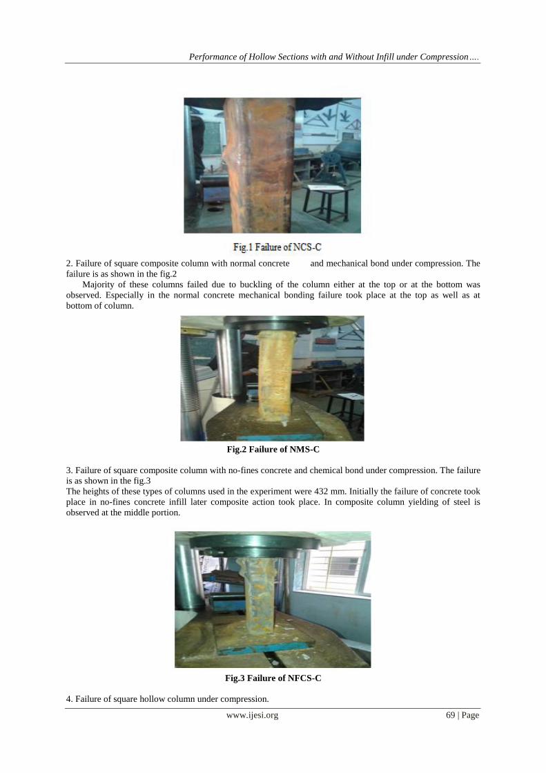
1. Failure of square composite column with normal concrete and chemical bond under compression. The
failure is as shown in the fig.1
The heights of these types of columns used in the experiment were 432 mm. majority of the column failed due
to buckling of the column near to middle portion. Especially in the normal concrete mostly failure took place at
the middle of the column.
Performance of Hollow Sections with and Without Infill under Compression….
www.ijesi.org 69 | Page
2. Failure of square composite column with normal concrete and mechanical bond under compression. The
failure is as shown in the fig.2
Majority of these columns failed due to buckling of the column either at the top or at the bottom was
observed. Especially in the normal concrete mechanical bonding failure took place at the top as well as at
bottom of column.
Fig.2 Failure of NMS-C
3. Failure of square composite column with no-fines concrete and chemical bond under compression. The failure
is as shown in the fig.3
The heights of these types of columns used in the experiment were 432 mm. Initially the failure of concrete took
place in no-fines concrete infill later composite action took place. In composite column yielding of steel is
observed at the middle portion.
Fig.3 Failure of NFCS-C
4. Failure of square hollow column under compression.

Performance of Hollow Sections with and Without Infill under Compression….
www.ijesi.org 70 | Page
Majority of these columns failed due to buckling of the column either at the top or at the bottom was
observed. Especially in the hollow square column buckling failure took place at the bottom of the column. The
failure is as shown in the fig.4
Fig.4 Failure of HS-C
5. Failure of rectangular composite column with normal
concrete and chemical bond under compression. The failure is as shown in the fig. 5
The heights of these types of columns used in the experiment were 300 mm. majority of the column failed due
to buckling of the column either at the top or at the bottom. Especially in the normal concrete mostly failure
took place at the top of the column due to buckling.
Fig.5 Failure of NCR-C
6. Failure of rectangular composite column with normal concrete and mechanical bond under compression. The
failure is as shown in the fig.6
The heights of these types of columns used in the experiment were 300 mm. majority of the column failed due
to buckling of the column either at the top or at the bottom. Especially in the normal concrete mostly failure
took place at the top of the column.

Performance of Hollow Sections with and Without Infill under Compression….
www.ijesi.org 71 | Page
Fig.6 Failure of NMR-C
7. Failure of rectangular composite column with no-fines concrete and chemical bond under compression. The
failure is as shown in the fig.7
The height of the column used in the experiment was 300 mm. Initially the failure of concrete took place in no-
fines concrete infill later composite action took place. In composite column yielding of steel is observed at the
middle portion.
Fig.7 Failure of NFCR-C
8. Failure of rectangular hollow column under compression.
Majority of these columns failed due to buckling of the column either at the top or at the bottom was observed.
Especially in the hollow rectangular column failure took place at the bottom of the column. The failure is as
shown in the fig.8
Fig.8 Failure of HR-C
3.2 Observation on Flexure Test
The flexure test is performed in the universal testing machine by applying concentrated load at the center of
the specimen. The span of the composite specimen used for flexure test is 400 mm. the specimens were
observed to fail at 110 kN. The crack pattern of the specimen occurred at the bottom of specimen. The observed
failure pattern is as shown in the figure below.

Performance of Hollow Sections with and Without Infill under Compression….
www.ijesi.org 72 | Page
Fig.9 Failure of the composite beam section
3.3 Load v/s Deflection Relationship between all types of square columns for compression test
Fig.10 Load v/s deflection relationship for HS-C, NCS-C, NMS-C, NFCS-C
Table 3. Summary of compression test results
Infill
type
Bonding
type Column Specifications
Ultim
ate
Load
(kN)
max
.defor
matio
n
(mm)
Hollow
Square
HSC1 182.0
5 2.32 HSC2
HSC3
Rectangular
HRC1 129.5
8 2.06 HRC2
HRC3
Normal
concret
e
Chemica
l Bond
Square
NCSC1 358.6
1 20.84 NCSC2
NCSC3
Rectangular
NCRC1 259.7
6 15.46 NCRC2
NCRC3
Normal
concret
e
Mechani
cal Bond
Square
NMSC1 456.7
8 19.91 NMSC2
NMSC3
Rectangular
NMRC1 325.4
4 14.68 NMRC2
NMRC3

Performance of Hollow Sections with and Without Infill under Compression….
www.ijesi.org 73 | Page
3.4 Load v/s lection
Relationship between all types of rectangular columns for compression test
Fig.11 Load v/s deflection relationship for HR-C, NCR-C, NMR-C, NFCRC
3.5 Load v/s Deflection Relationship between all types of square beams for flexure test
Fig.12 Load v/s deflection relationship for HS-F, NCS-F, NMS-F, NFCS-F
3.6 Load v/s Deflection Relationship between all types of rectangular beams for flexure test
Fig.13 Load v/s deflection relationship for HR-F, NCR-F, NMR-F, NFCR-F
Table 3. Summary of compression test results
No-
fines
concret
e
Chemica
l Bond
Square
NFCSC1
204.4 5.42 NFCSC2
NFCSC3
Rectangular
NFCRC1 171.5
5 5.18 NFCRC2
NFCRC3

Performance of Hollow Sections with and Without Infill under Compression….
www.ijesi.org 74 | Page
Table 4. Summary of flexure test results
IV. Numerical Analysis The nonlinear analysis of composite sections is done by using ansys workbench release 16.2.
Element type
In this step selection of materials has been done i.e. concrete and structural steel.
4.1 Concrete (Solid 65)
SOLID65 is used for the three-dimensional modeling of solids with or without reinforcing bars
(rebar’s). The solid is capable of cracking in tension and crushing in compression. In concrete applications, for
example, the solid capability of the element may be used to model the concrete while the rebar capability is
available for modeling reinforcement behavior. Other cases for which the element is also applicable would be
reinforced composites (such as fiberglass), and geological materials (such as rock). The element is defined by
eight nodes having three degrees of freedom at each node: translations in the nodal x, y, and z directions. Up to
three different rebar specifications may be defined.
Infill
type
Bondi
ng
type
Beam Specifications
Ultima
te
Load
(kN)
Max.
Defle
ction
(mm)
Hollow
Square
HSF1
25.23 12.24 HSF2
HSF3
Rectangula
r
HRF1
21.90 3.44 HRF2
HRF3
Normal
concret
e
Chem
ical
Bond
Square
NCSF1
88.7 33.40 NCSF2
NCSF3
Rectangula
r
NCRF1
84.46 44.13 NCRF2
NCRF3
Normal
concret
e
Mech
anical
Bond
Square
NMSF1
103.71 31.40 NMSF2
NMSF3
Rectangula
r
NMRF1
106.18 58.52 NMRF2
NMRF3
No-
fines
concret
e
Chem
ical
Bond
Square
NFCSF1
58.11 66.82 NFCSF2
NFCSF3
Rectangula
r
NFCRF1
59.71 70.19 NFCRF2
NFCRF3

Performance of Hollow Sections with and Without Infill under Compression….
www.ijesi.org 75 | Page
Fig.14 Solid 65 element
4.2 Steel (Link 8)
A link 8 element is used to model steel reinforcement. This element is a 3-D spar element and it has two nodes
with three degrees of freedom translations in the nodal x, y and z directions. This element is capable of plastic
deformation and element is shown in figure below,
Fig.15 Link 8 element
Table 5. Compressiontest results for NCS-C
Column
name Experimental Numerical
Normal
chemical
square
Load
(kN)
Deformation
(mm)
Load
(kN)
Deformation
(mm)
0 0 0 0
40 0.16 40 0.1520
80 0.57 80 0.5446
120 1.03 120 0.9683
160 1.49 160 1.406
200 1.97 200 1.8429
240 2.89 240 2.7015
280 5.93 280 5.5564
320 17.2 320 15.621
340 19.15 340 17.183

Performance of Hollow Sections with and Without Infill under Compression….
www.ijesi.org 76 | Page
Fig.16 Deformation of NCS-C
Fig.17 Deformation of NCS-C

Performance of Hollow Sections with and Without Infill under Compression….
www.ijesi.org 77 | Page
Fig.18 Deformation of NCS-C
Fig.19 Comparison of experimental and FEA results of NCS-C under compression
Table 6. Flexural test results for NCR-F
Column
Name Experimental Numerical
Normal
chemical
rectangular
Load
(kN)
Deflection
(mm)
Load
(kN)
Deflection
(mm)
0 0 0 0
10 0.09 10 0.08858
20 0.20 20 0.1890
30 0.53 30 0.4977
40 1.01 40 0.9863
50 1.30 50 1.2679
60 1.96 60 1.8323
70 3.80 70 3.4098

Performance of Hollow Sections with and Without Infill under Compression….
www.ijesi.org 78 | Page
Fig.20 Deflection of NCR-F
Fig.21 Deflection of NCR-F
Fig.22 Deflection of NCR-F

Performance of Hollow Sections with and Without Infill under Compression….
www.ijesi.org 79 | Page
Fig.23 Comparison of experimental and FEA results of NCR-F under flexure
V. Conclusions
From experimental investigation of hollow as well as composite columns and beams following conclusions are
derived,
1. The strength of the hollow section with infillednormal concrete is observed to be greater than the hollow
section without infilled concrete and other forms of composite section in compression as well as in flexure.
The percentage increase in the compressive strength of the square composite section as compare to hollow
section is as shown below,
Composite columns with chemical bonding - 45 to 50%.
composite columns with mechanical bonding - 60 to 65%
Composite columns with No-fines concrete - 10 to 20%
The percentage increases in the flexural strength of rectangular composite section as compare to hollow section
isas shown below,
Composite section with chemical bonding -70 to75%
Composite section with mechanical bonding –70 to 80%
Composite columns with No-fines concrete – 55 to 65%
2. The compressive strength of square normal concrete composite section with mechanical bonding is maximum
as compared to the other types of square and rectangular hollow sections, square and rectangular composite
sections such as chemical bond with No-fines concrete and chemical bond with normal concrete
3. The flexural strength of rectangular normal concrete composite section with mechanical bonding is maximum
as compared to the other types of square and rectangular hollowsections, square and rectangular composite
sections such as chemical bond with No-fines concrete, chemical bond with normal concrete.
4. The experimental results of NCS-C and NCR-F are compared with the numerical analysis results of same
composite sections. In comparison with the experimental results the numerical study shows similar variation.
References [1]. S. Mathankumar and M. Anbarasan, “Finite element analysis of steel tubularsection filled with concrete”,International Journal of
Innovative Research in Science,Engineering and Technology, Vol. 05, Issue 06, 2016, pp. 11775-11779.
[2]. S. Kurian, D. Paulose and S. Mohan, “Studyon concrete filled steel tube”, IOSR Journal of Mechanical and Civil Engineering,
2016, pp. 25-33.
[3]. S. Das, G. Vimalanandan and S. Selvan, “Investigation on flexural behaviour of GGBS concreteinfilled steel tubular sections”, International Research Journal of Engineering and Technology, Vol. 03, Issue: 04, 2016,pp. 2663-2669.
[4]. ShehdehGhannam “Buckling of concrete filled steel tubular slender column”, International Journal of Research in Civil
Engineering, Architecture and Design, 2015, Vol. 3, Issue 1, pp. 41-47. [5]. R. Bharteshand B. Sureshchandra, “Experimental and numerical investigation of hollow section with and without infill under
compression and flexure” International Journal of Engineering Research & Technology, Vol. 03, Issue 07, 2014, pp.869-873.
[6]. B.Vijaylaxmiand M. Chitawadag, “Finite element analysis of concrete filled steel tube subjected to flexure”,International Journal of Engineering Inventions, Vol. 3, Issue 12, 2014,PP: 18-28.
[7]. F. TittarelliandA. Mobili, “Sustainable and durable no-fines concrete for vertical applications”,International Journal of Chemical,
Environmental & Biological Sciences, Vol. 1, Issue 5, 2013, pp. 784-788. [8]. K. Chithiraand K. Baskar, “Experimental and numerical investigation on circular CFSTs columns under eccentric load condition
with and without shear connectors”, International Journal of Earth Sciences and Engineering, Vol. 05, No. 01, 2012, pp. 169-179.
[9]. A. Patidar, “Behavior of concrete filled rectangular steel tube column”, IOSR Journal of Mechanical and Civil Engineering, Vol. 4, Issue 2, 2012, pp. 46-52.

Performance of Hollow Sections with and Without Infill under Compression….
www.ijesi.org 80 | Page
[10]. E. MohanrajandS. Kandasamy, “Experimental behavior of axially loaded slender hollow steel columns in-filled with rubber
concrete”, 2010, pp. 1-6. [11]. S. ArivalaganandS. Kandasamy, “Finite element analysis on the flexural behaviour of concrete filled steel tube beams”, Journal of
Theoretical and Applied Mechanics, Vol. 08, Issue-02, 2010,pp. 505-516.
[12]. T. ZhongandH. Lin-Hai Han, “Compressive and flexural behaviour of CFRP-repaired concrete-filled steel tubes after exposure to fire”, Journal of Constructional Steel Research 63, 2007, pp. 1116–1126.
[13]. H. Lin, H. Lu, G. Yao and F. Liao, “Flexural behavior of concrete-filled steel tubes”, Journal of Constructional Steel Research,
2004, pp. 313–337. [14]. K. Sakino, H. Nakahara, S. Morinoand I. Nishiyama, “Behavior of Centrally Loaded Concrete-Filled Steel-Tube Short
Columns”,Journal of Structural Engineering, ASCE, 2004, pp. 180-188.
[15]. C. Huang, Y. Yeh, G. Liu, H. Hu, K. Tsai, Y. Weng, S. Wang and M. Wu, “Axial load behavior of stiffened concrete-filled steel columns”,Journal of Structural Engineering, 2002, pp. 1222-1230.
[16]. A. Famand S. Rizkalla, “Flexural behavior of concrete-filled fiber reinforced polymer circular tubes”,Journal of Composites
Construction, 2002, pp. 123-132. [17]. N. Shanmugamand B. Lakshmi, “State of the art report on steel–concrete composite columns”, Journal of Constructional Steel
Research, 2001, pp.1041–1080.
Q. YueandD. Kennedy, “The flexural behaviour of concrete-filled hollow structural sections”,Canada Journal of Civil Engineering, Vol. 21, 1994, pp. 111-130.
[18]. Bureau of Indian Standards. “Guidelines for Concrete Mix Design Proportioning”, IS 10262-2009, First Revised Edition, New
Delhi.
[19]. Bureau of Indian Standards. “Hollow Steel Sections for Structural Use Specifications”, IS 4923-1997, First Revised Edition, New
Delhi.
[20]. Indian Standard Institution. “Code of Practice for Composite Construction in Structural Steel and Concrete”, IS 11384-1985, New Delhi.
[21]. American Institute of Steel Construction. “Specifications for Structural Steel Buildings”, AISC-2005, Chicago.
[22]. British Standards. “Design of Composite Steel and Concrete Structures”, BS EN 1994-2005, Europe.
International Journal of Engineering Science Invention (IJESI) is UGC approved Journal with Sl. No.
3822, Journal no. 43302.
Mukesh Ghadge “Performance of Hollow Sections with and Without Infill under Compression and
Flexure” International Journal of Engineering Science Invention (IJESI), vol. 07, no. 02, 2018, pp. 67–
80.