Embed Size (px)
Citation preview
Brigham Young University Brigham Young University
BYU ScholarsArchive BYU ScholarsArchive
Theses and Dissertations
2005-01-04
Performance of Concrete Bridge Deck Joints Performance of Concrete Bridge Deck Joints
Lik Hang Yuen Brigham Young University - Provo
Follow this and additional works at: https://scholarsarchive.byu.edu/etd
Part of the Civil and Environmental Engineering Commons
BYU ScholarsArchive Citation BYU ScholarsArchive Citation Yuen, Lik Hang, "Performance of Concrete Bridge Deck Joints" (2005). Theses and Dissertations. 236. https://scholarsarchive.byu.edu/etd/236
This Thesis is brought to you for free and open access by BYU ScholarsArchive. It has been accepted for inclusion in Theses and Dissertations by an authorized administrator of BYU ScholarsArchive. For more information, please contact [email protected], [email protected].

PERFORMANCE OF CONCRETE BRIDGE DECK JOINTS
by
Lik Hang Yuen
A thesis submitted to the faculty of
Brigham Young University
in partial fulfillment of the requirement for the degree of
Master of Science
Department of Civil and Environmental Engineering
Brigham Young University
April 2005
BRIGHAM YOUNG UNIVERSITY
GRADUATE COMMITTEE APPROVAL
of a thesis submitted by
Lik Hang Yuen
This thesis has been read by each member of the following graduate committee and by majority vote has been found to be satisfactory. Date W. Spencer Guthrie, Chair Date Mitsuru Saito Date Fernando S. Fonseca
BRIGHAM YOUNG UNIVERSITY
As chair of the candidate’s graduate committee, I have read the thesis of Lik Hang Yuen in its final form and have found that (1) its format, citations, and bibliographical style are consistent and acceptable and fulfill university and department style requirement; (2) its illustrative materials including figures, tables, and charts are in place; and (3) the final manuscript is satisfactory to the graduate committee and is ready for submission to the university library. Date W. Spencer Guthrie Chair, Graduate Committee Accepted for the Department E. James Nelson Graduate Coordinator Accepted for the College Douglas M. Chabries
Dean, Ira A. Fulton College of Engineering and Technology
ABSTRACT
PERFORMANCE OF CONCRETE BRIDGE DECK JOINTS
Lik Hang Yuen
Department of Civil and Environmental Engineering
Master of Science
The purpose of this research was to identify the types of joints available for use
on concrete bridge decks and to investigate the performance characteristics of each type,
including primary functions and movement ranges. Eleven reports on joint performance
published by state departments of transportation and universities nationwide were
analyzed in order to obtain information on joint performance problems typically
encountered by state transportation agencies. In addition, test methods and specifications
provided by the American Society for Testing and Materials (ASTM) were reviewed for
application by bridge engineers to ensure the adequacy of deck joints.
The research indicates that compression seals should be used to accommodate
movements less than 2 in., while strip seals should be used for movements up to 4 in. A
lubricant conforming to ASTM D 4070, Standard Specification for Adhesive Lubricant
for Installation of Preformed Elastomeric Bridge Compression Seals in Concrete
Structures, should be applied during installation of compression and strip seals. Finger
joints with troughs should be used instead of reinforced elastomeric joints and modular
elastomeric joints for movements greater than 4 in. To maximize the performance of
finger joints, ensuring adequate structural properties of the finger plates and proper
installation of the troughs is necessary.

When Utah Department of Transportation (UDOT) engineers conduct in-house
experiments on bridge deck joints in the future, they should be more consistent and
provide more information about the bridge structures in reports, including, for example,
the anticipated deck movements, average daily traffic, and design loads for the bridges.
Also, UDOT should establish a consistent evaluation program for investigating joint
products during the approval process. The program should include quantitative
measurements including, but not limited to, debris accumulation, adhesion and cohesion
of the joint material, condition of anchorages and header materials, watertightness of the
joints, condition of the concrete edges of the deck, deterioration of substructures, ride
quality, noise level under travel, and general appearance of the joints. These
experimental data should then be thoroughly documented in the resulting reports.
ACKNOWLEDGMENTS
The author wishes to express sincere thanks and appreciation to Dr. W. Spencer
Guthrie for providing invaluable insight and direction throughout the course of this
research. A thank-you is also extended to Dr. Mitsuru Saito and Dr. Fernando S. Fonseca
for serving on the graduate committee.
The author also wishes to thank the Utah Department of Transportation for
funding this research.
Last but not least, a heartfelt gratitude is extended to my wife, Wing See Lam,
whose continual support and encouragement have enabled me to complete this phase of
my education.
TABLE OF CONTENTS
ABSTRACT....................................................................................................................... iv ACKNOWLEDGMENTS ................................................................................................. vi LIST OF FIGURES .............................................................................................................x CHAPTER 1. INTRODUCTION .......................................................................................1 1.1 Problem Statement .............................................................................................1 1.2 Outline of Report ...............................................................................................2 CHAPTER 2. TYPES OF BRIDGE DECK JOINTS.........................................................3 2.1 Purpose of Bridge Deck Joints...........................................................................3 2.2 Open Joints.........................................................................................................3 2.2.1 Butt Joints ...........................................................................................4 2.2.2 Sliding Plate Joints..............................................................................5 2.2.3 Finger Joints........................................................................................5 2.2.4 Drainage Troughs................................................................................6 2.3 Closed Joints ......................................................................................................7 2.3.1 Poured Seals........................................................................................7 2.3.2 Asphalt Plug Joints .............................................................................8 2.3.3 Compression Seals ..............................................................................9 2.3.4 Strip Seals .........................................................................................10 2.3.5 Reinforced Elastomeric Joints ..........................................................11 2.3.6 Modular Elastomeric Joints ..............................................................13 2.4 Summary ..........................................................................................................13 CHAPTER 3. PERFORMANCE EVALUATIONS OF BRIDGE DECK JOINTS ........15 3.1 Performance History ........................................................................................15 3.2 Compression Seals ...........................................................................................17 3.3 Strip Seals ........................................................................................................18 3.4 Reinforced Elastomeric Joints .........................................................................20 3.5 Modular Elastomeric Joints .............................................................................21 3.6 Finger Joints with Troughs ..............................................................................23 3.7 Elastomeric Nosing Materials..........................................................................25 3.8 Summary ..........................................................................................................28
vii
CHAPTER 4. UDOT EXPERIMENTAL JOINT EVALUATIONS ..............................31 4.1 In-House UDOT Research...............................................................................31 4.2 Koch-Bestway Bridge Joint Repair System.....................................................31 4.3 Dow Corning Silicone Joint Sealant ................................................................32 4.4 Silspec Polymer Nosing System with Dow Corning Silicone Joint Sealant ...32 4.5 Sikaflex Low-Modulus Elastomeric Polyurethane Joint Sealant.....................33 4.6 Flexcon 2000 Joint Sealant System with Flexcon A/C Nosing .......................33 4.7 Summary ..........................................................................................................34 CHAPTER 5. STANDARD SPECIFICATIONS AND TESTS ......................................37 5.1 Sources of Specifications and Tests.................................................................37 5.2 Poured Seals.....................................................................................................38 5.2.1 Specimen Preparation .......................................................................38 5.2.2 Sealant Curing...................................................................................39 5.2.3 Testing...............................................................................................40 5.2.4 Sealant Selection...............................................................................40 5.3 Compression Seals ...........................................................................................41 5.3.1 Recovery ...........................................................................................41 5.3.2 Compression-Deflection Properties ..................................................42 5.3.3 Tensile Strength ................................................................................43 5.3.4 Durometer Hardness .........................................................................43 5.3.5 Oven Aging.......................................................................................44 5.3.6 Oil Swell ...........................................................................................44 5.3.7 Ozone Resistance ..............................................................................44 5.4 Strip Seals ........................................................................................................45 5.4.1 Tensile Strength ................................................................................45 5.4.2 Durometer Hardness .........................................................................46 5.4.3 Oven Aging.......................................................................................46 5.4.4 Oil Swell ...........................................................................................46 5.4.5 Ozone Resistance ..............................................................................46 5.4.6 Low Temperature Stiffening.............................................................46 5.4.7 Compression Set ...............................................................................47 5.5 Adhesive Lubricants ........................................................................................47 5.5.1 Solids Content...................................................................................48 5.5.2 Viscosity and Shear Ratio.................................................................49 5.5.3 Lubricating Life ................................................................................49 5.5.4 Sag.....................................................................................................49 5.5.5 Peel Strength .....................................................................................49 5.6 Summary ..........................................................................................................50 CHAPTER 6. DESIGN, INSTALLATION, AND MAINTENANCE OF JOINTS AND ANCHORAGES ..........................................................51 6.1 Procedural Recommendations .........................................................................51 6.2 Finger Joints.....................................................................................................51 6.2.1 Design ...............................................................................................52 6.2.2 Installation.........................................................................................52
viii

6.2.3 Maintenance......................................................................................53 6.3 Poured Seals.....................................................................................................53 6.3.1 Design ...............................................................................................53 6.3.2 Installation.........................................................................................54 6.3.3 Maintenance......................................................................................55 6.4 Asphalt Plug Joints ..........................................................................................55 6.4.1 Design ...............................................................................................55 6.4.2 Installation.........................................................................................55 6.4.3 Maintenance......................................................................................56 6.5 Compression Seals ...........................................................................................56 6.5.1 Design ...............................................................................................56 6.5.2 Installation.........................................................................................57 6.5.3 Maintenance......................................................................................57 6.6 Strip Seals ........................................................................................................57 6.6.1 Design ...............................................................................................57 6.6.2 Installation.........................................................................................58 6.6.3 Maintenance......................................................................................58 6.7 Reinforced Elastomeric Joints .........................................................................58 6.7.1 Design ...............................................................................................58 6.7.2 Installation.........................................................................................59 6.7.3 Maintenance......................................................................................59 6.8 General Recommendations for Joints ..............................................................59 6.8.1 Design ...............................................................................................60 6.8.2 Installation.........................................................................................60 6.8.3 Maintenance......................................................................................61 6.9 General Recommendations for Anchorage Systems........................................61 6.9.1 Design ...............................................................................................61 6.9.2 Installation.........................................................................................62 6.10 Summary ........................................................................................................62 CHAPTER 7. CONCLUSION..........................................................................................63 7.1 Summary ..........................................................................................................63 7.2 Findings............................................................................................................64 7.3 Recommendations............................................................................................66 CHAPTER 8. REFERENCES ..........................................................................................69
ix
LIST OF FIGURES
Figure 2.1 Armored Butt Joint ......................................................................................4 Figure 2.2 Sliding Plate Joint ........................................................................................5 Figure 2.3 Finger Joint ..................................................................................................6 Figure 2.4 Poured Seal ..................................................................................................8 Figure 2.5 Asphalt Plug Joint ........................................................................................9 Figure 2.6 Cellular Compression Joint........................................................................10 Figure 2.7 ACME Strip Seal .......................................................................................11 Figure 2.8 Fel Span T30 Sheet Seal ............................................................................12 Figure 2.9 Transflex 400A Plank Seal ........................................................................12 Figure 2.10 ACME Modular Elastomeric Joint ............................................................13 Figure 3.1 Design of First Closed Joint.......................................................................16 Figure 3.2 Design of First Compression Seal..............................................................16 Figure 3.3 X.J.S. Expansion Joint System ..................................................................27 Figure 3.4 Delcrete Elastomeric Concrete/Steelflex Strip Seal System......................28
x
CHAPTER 1
INTRODUCTION
1.1 PROBLEM STATEMENT
The purpose of this research was to identify the types of joints available for use on
concrete bridge decks and to investigate the performance characteristics of each type,
including primary functions and movement ranges. Bridge deck joints are used to protect
the edges of the concrete deck from vehicle loads, seal the joint openings, and
accommodate concrete deck movements that are produced by temperature changes and
creep and shrinkage of concrete. Although the joints are among the smallest components
in a bridge structure, the integrity of the whole structure is affected when the joints fail.
The Utah Department of Transportation (UDOT) has increasing need for rapid and
reliable joint treatments to prevent water ingress and subsequent deterioration of bridge
components through the corrosive action of deicing salts and to ensure an adequate riding
surface for the traveling public.
Many factors contribute to the failure of bridge deck joints. The failure is not
necessarily caused by the joint material itself; it can also be caused by careless design,
improper installation, and inadequate maintenance. Joint failure is a nationwide problem
in the United States; therefore, methods used to remedy joint failure by other state
departments of transportation are important considerations in this research.
In past years, UDOT conducted several in-house bridge deck joint experiments in
order to evaluate new joint products. These experiments are reviewed in this report to
identify important findings relative to past joint performance on Utah bridges. In
addition to guidelines utilized by state transportation agencies, test methods and
specifications are available through the American Society for Testing and Materials
(ASTM). If strictly followed, these specifications should ensure that adequate joint
1
materials are used in bridge deck joint systems. Besides joint materials, UDOT is also
interested in identifying and evaluating joint header materials and methods for use when
replacing entire joint systems.
1.2 OUTLINE OF REPORT
Chapter 2 of this report provides an overview of the components of joint types
that are available in the bridge industry, including the primary functions of these joints.
In addition, a comprehensive review of joint studies published by researchers at
universities and state departments of transportation (DOTs) nationwide is given in
Chapter 3; the chapter provides background information on the performance of joints and
joint headers. Furthermore, reports of in-house experiments on bridge deck joints
performed by UDOT between 1992 and 1999 are reviewed in Chapter 4. Additionally,
information obtained from a review of ASTM standards is given in Chapter 5 for
consideration by UDOT. Numerous important practices employed by transportation
agencies for the design, installation, and maintenance of joint systems are highlighted in
Chapter 6. If these practices are closely followed, the service lives of bridge deck joints
should be maximized. Conclusions and recommendations are given in Chapter 7 of this
report.
2
CHAPTER 2
TYPES OF BRIDGE DECK JOINTS
2.1 PURPOSE OF BRIDGE DECK JOINTS
Concrete bridge decks experience contraction and expansion as a result of exposure to the
environment and the imposition of loads (1). If the contraction movements are
excessively restrained, cracking may occur in the concrete. On the other hand, if
expansion movements are restrained, distortion or crushing may result (1). One of the
means for accommodating contraction and expansion without compromising the integrity
of the structure is to provide joints between the bridge deck slabs (1).
Bridge deck joints can be classified as either open-joint or closed-joint types (2).
The ability to allow water and debris to pass through joint openings is the main
characteristic distinguishing open joints from closed joints. Because each joint type has
advantages and disadvantages, bridge engineers need to be very familiar with the
characteristics of the various joints available for use in concrete bridge decks. This
chapter presents a comprehensive review of both open-joint and closed-joint types. As
the performance of several common joints is discussed in Chapter 3, no attempt is made
to compare joints in this chapter.
2.2 OPEN JOINTS
Open joints were primarily designed to permit cyclic and long-term movement, support
traffic, pass water and debris, and survive service (3). Butt joints (either with or without
armor angles), sliding plate joints, and finger joints, which are listed in order of
increasing amounts of movement they can effectively accommodate, are the most
3
commonly used open joints (2). Details are provided for these types of open joints, as
well as for drainage troughs, in the following sections.
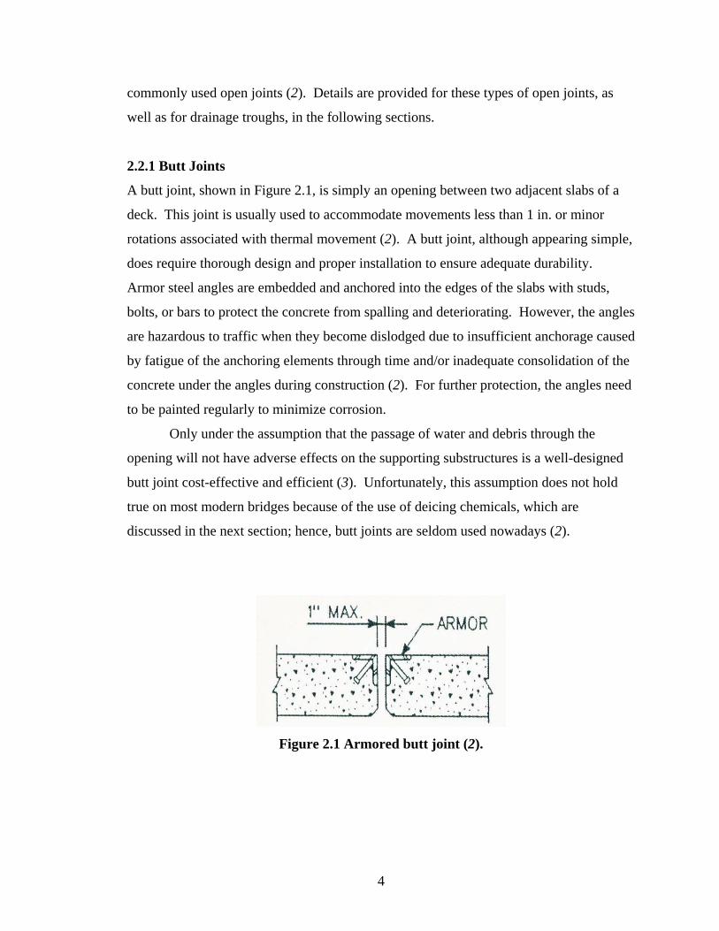
2.2.1 Butt Joints
A butt joint, shown in Figure 2.1, is simply an opening between two adjacent slabs of a
deck. This joint is usually used to accommodate movements less than 1 in. or minor
rotations associated with thermal movement (2). A butt joint, although appearing simple,
does require thorough design and proper installation to ensure adequate durability.
Armor steel angles are embedded and anchored into the edges of the slabs with studs,
bolts, or bars to protect the concrete from spalling and deteriorating. However, the angles
are hazardous to traffic when they become dislodged due to insufficient anchorage caused
by fatigue of the anchoring elements through time and/or inadequate consolidation of the
concrete under the angles during construction (2). For further protection, the angles need
to be painted regularly to minimize corrosion.
Only under the assumption that the passage of water and debris through the
opening will not have adverse effects on the supporting substructures is a well-designed
butt joint cost-effective and efficient (3). Unfortunately, this assumption does not hold
true on most modern bridges because of the use of deicing chemicals, which are
discussed in the next section; hence, butt joints are seldom used nowadays (2).
Figure 2.1 Armored butt joint (2).
4
2.2.2 Sliding Plate Joints
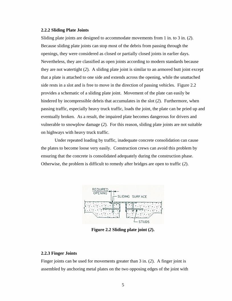
Sliding plate joints are designed to accommodate movements from 1 in. to 3 in. (2).
Because sliding plate joints can stop most of the debris from passing through the
openings, they were considered as closed or partially closed joints in earlier days.
Nevertheless, they are classified as open joints according to modern standards because
they are not watertight (2). A sliding plate joint is similar to an armored butt joint except
that a plate is attached to one side and extends across the opening, while the unattached
side rests in a slot and is free to move in the direction of passing vehicles. Figure 2.2
provides a schematic of a sliding plate joint. Movement of the plate can easily be
hindered by incompressible debris that accumulates in the slot (2). Furthermore, when
passing traffic, especially heavy truck traffic, loads the joint, the plate can be pried up and
eventually broken. As a result, the impaired plate becomes dangerous for drivers and
vulnerable to snowplow damage (2). For this reason, sliding plate joints are not suitable
on highways with heavy truck traffic.
Under repeated loading by traffic, inadequate concrete consolidation can cause
the plates to become loose very easily. Construction crews can avoid this problem by
ensuring that the concrete is consolidated adequately during the construction phase.
Otherwise, the problem is difficult to remedy after bridges are open to traffic (2).
Figure 2.2 Sliding plate joint (2).
2.2.3 Finger Joints
Finger joints can be used for movements greater than 3 in. (2). A finger joint is
assembled by anchoring metal plates on the two opposing edges of the joint with
5
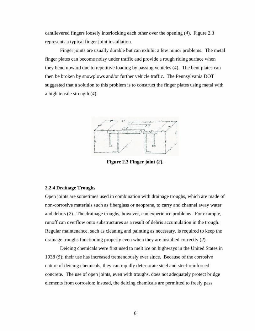
cantilevered fingers loosely interlocking each other over the opening (4). Figure 2.3
represents a typical finger joint installation.
Finger joints are usually durable but can exhibit a few minor problems. The metal
finger plates can become noisy under traffic and provide a rough riding surface when
they bend upward due to repetitive loading by passing vehicles (4). The bent plates can
then be broken by snowplows and/or further vehicle traffic. The Pennsylvania DOT
suggested that a solution to this problem is to construct the finger plates using metal with
a high tensile strength (4).
Figure 2.3 Finger joint (2).
2.2.4 Drainage Troughs
Open joints are sometimes used in combination with drainage troughs, which are made of
non-corrosive materials such as fiberglass or neoprene, to carry and channel away water
and debris (2). The drainage troughs, however, can experience problems. For example,
runoff can overflow onto substructures as a result of debris accumulation in the trough.
Regular maintenance, such as cleaning and painting as necessary, is required to keep the
drainage troughs functioning properly even when they are installed correctly (2).
Deicing chemicals were first used to melt ice on highways in the United States in
1938 (5); their use has increased tremendously ever since. Because of the corrosive
nature of deicing chemicals, they can rapidly deteriorate steel and steel-reinforced
concrete. The use of open joints, even with troughs, does not adequately protect bridge
elements from corrosion; instead, the deicing chemicals are permitted to freely pass
6

through the deck openings. For this reason, open joints have lost favor with most bridge
engineers, particularly in locations where deicing chemicals are used extensively (2).
2.3 CLOSED JOINTS
Preventing the passage of water, deicing salts, and debris through bridge deck joints has
become increasingly important in bridge engineering. The challenge is to develop a cost-
effective, durable, and watertight joint that can stop water intrusion while still
accommodating the anticipated contraction and expansion movements of the decks and
providing good riding quality. Many kinds of closed joints have been invented to provide
these functions, including poured seals, asphalt plug joints, compression seals, strip seals,
reinforced elastomeric joints, and modular elastomeric seals as discussed in the following
sections.
2.3.1 Poured Seals
As the name indicates, the poured seal is a pour-in-place sealer. A typical poured seal is
shown in Figure 2.4. Poured seals can only accommodate movements of 0.25 in. or less
(3). Heated asphalt or coal-tar products were used to construct poured seals in earlier
days, but silicone is used today (3). Modern poured seals generally consist of a viscous,
adhesive, and pourable waterproof silicone placed near the top of the joint opening. A
pre-formed filler material, or backer rod, is pressed into the opening before the sealant is
poured to prevent the sealant from flowing down the joint.
After the sealant cures, it should remain flexible and retain its bond to the
concrete joint faces (3). Bonding is enhanced when the joint is thoroughly cleaned prior
to placement of the sealant (6). Also, poured seals work best if the sealant is poured
when the ambient temperature is at the middle of the historical temperature range so that
the opening is at its midpoint (2).
Poured seals are easy to repair, as only the failed portions need to be removed and
replaced. Furthermore, the repair of poured seals minimizes traffic delay because it does
not require closure of all the traffic lanes (7).
7
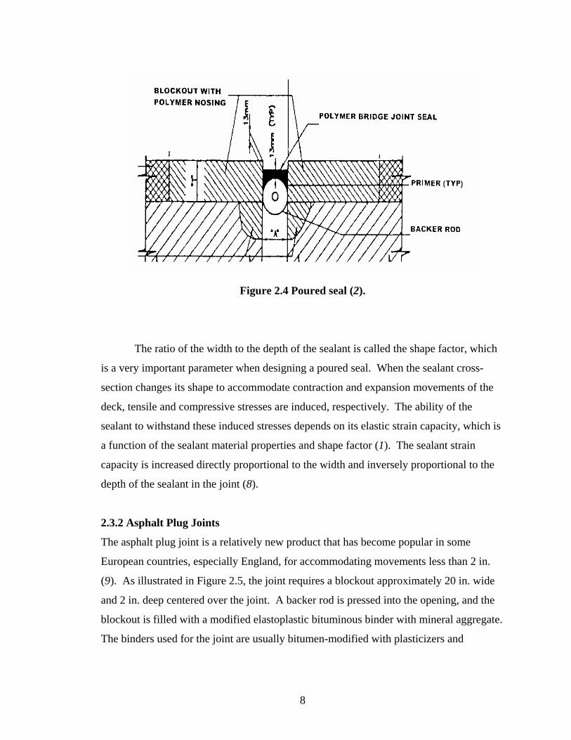
Figure 2.4 Poured seal (2).
The ratio of the width to the depth of the sealant is called the shape factor, which
is a very important parameter when designing a poured seal. When the sealant cross-
section changes its shape to accommodate contraction and expansion movements of the
deck, tensile and compressive stresses are induced, respectively. The ability of the
sealant to withstand these induced stresses depends on its elastic strain capacity, which is
a function of the sealant material properties and shape factor (1). The sealant strain
capacity is increased directly proportional to the width and inversely proportional to the
depth of the sealant in the joint (8).
2.3.2 Asphalt Plug Joints
The asphalt plug joint is a relatively new product that has become popular in some
European countries, especially England, for accommodating movements less than 2 in.
(9). As illustrated in Figure 2.5, the joint requires a blockout approximately 20 in. wide
and 2 in. deep centered over the joint. A backer rod is pressed into the opening, and the
blockout is filled with a modified elastoplastic bituminous binder with mineral aggregate.
The binders used for the joint are usually bitumen-modified with plasticizers and
8
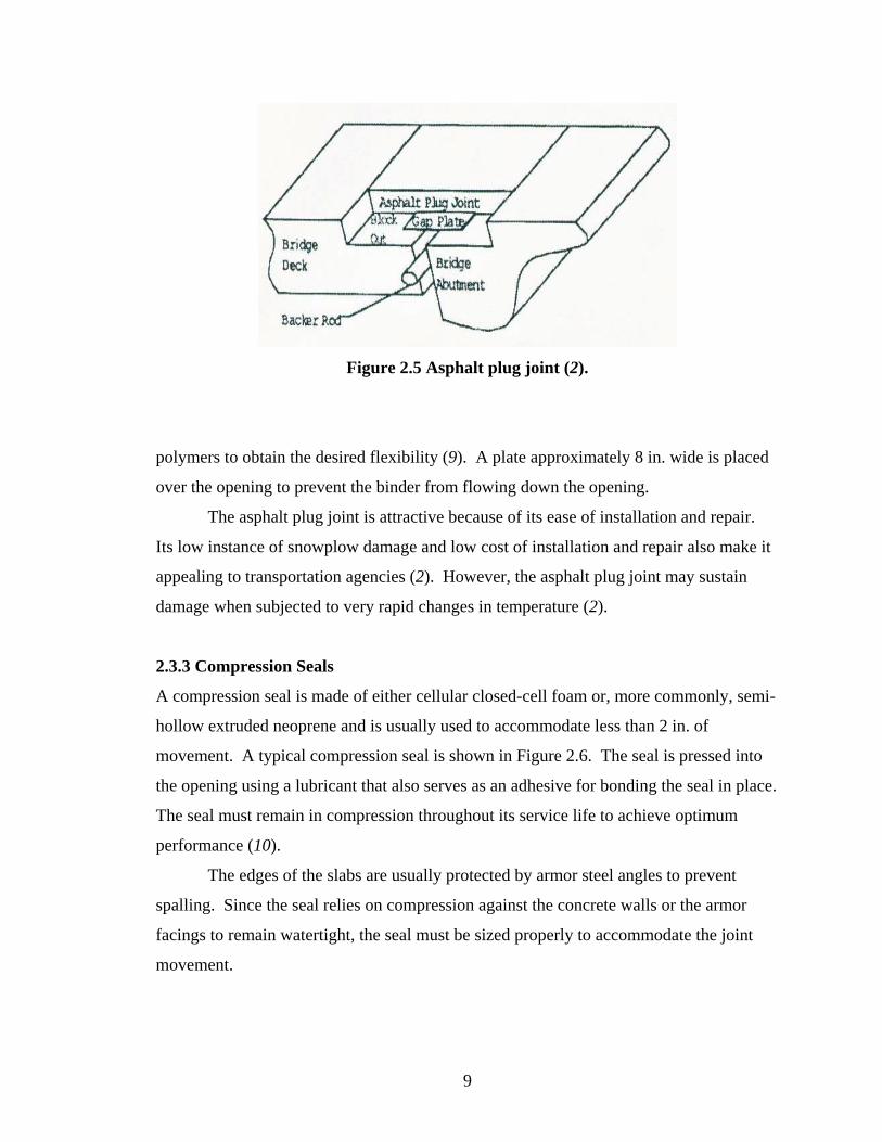
Figure 2.5 Asphalt plug joint (2).
polymers to obtain the desired flexibility (9). A plate approximately 8 in. wide is placed
over the opening to prevent the binder from flowing down the opening.
The asphalt plug joint is attractive because of its ease of installation and repair.
Its low instance of snowplow damage and low cost of installation and repair also make it
appealing to transportation agencies (2). However, the asphalt plug joint may sustain
damage when subjected to very rapid changes in temperature (2).
2.3.3 Compression Seals
A compression seal is made of either cellular closed-cell foam or, more commonly, semi-
hollow extruded neoprene and is usually used to accommodate less than 2 in. of
movement. A typical compression seal is shown in Figure 2.6. The seal is pressed into
the opening using a lubricant that also serves as an adhesive for bonding the seal in place.
The seal must remain in compression throughout its service life to achieve optimum
performance (10).
The edges of the slabs are usually protected by armor steel angles to prevent
spalling. Since the seal relies on compression against the concrete walls or the armor
facings to remain watertight, the seal must be sized properly to accommodate the joint
movement.
9

Figure 2.6 Cellular compression joint (2).
The overall advantages of compression seals are watertightness, relative ease of
installation, and cost effectiveness (11). The performance of a compression seal depends
on the quality of the installation and the selection of the seal size and material. Some
compression seal materials may be ozone-sensitive (11).
2.3.4 Strip Seals
As shown in Figure 2.7, a strip seal consists of a flexible neoprene membrane attached to
two opposing side rails. The neoprene membrane is pre-molded into a “V” shape that
folds as the slabs expand and unfolds as the slabs contract. The joint can accommodate
movements up to 4 in. (2).
If a strip seal is set too far below the riding surface, incompressible debris can
accumulate in the joint quickly. Consequently, the neoprene membrane can be torn,
punctured, or pulled from its attachment location when passing traffic impacts the
contaminated joint (12). Nonetheless, when the strip seal is installed and maintained
properly, it has a relatively long service life and adequate watertightness.
10
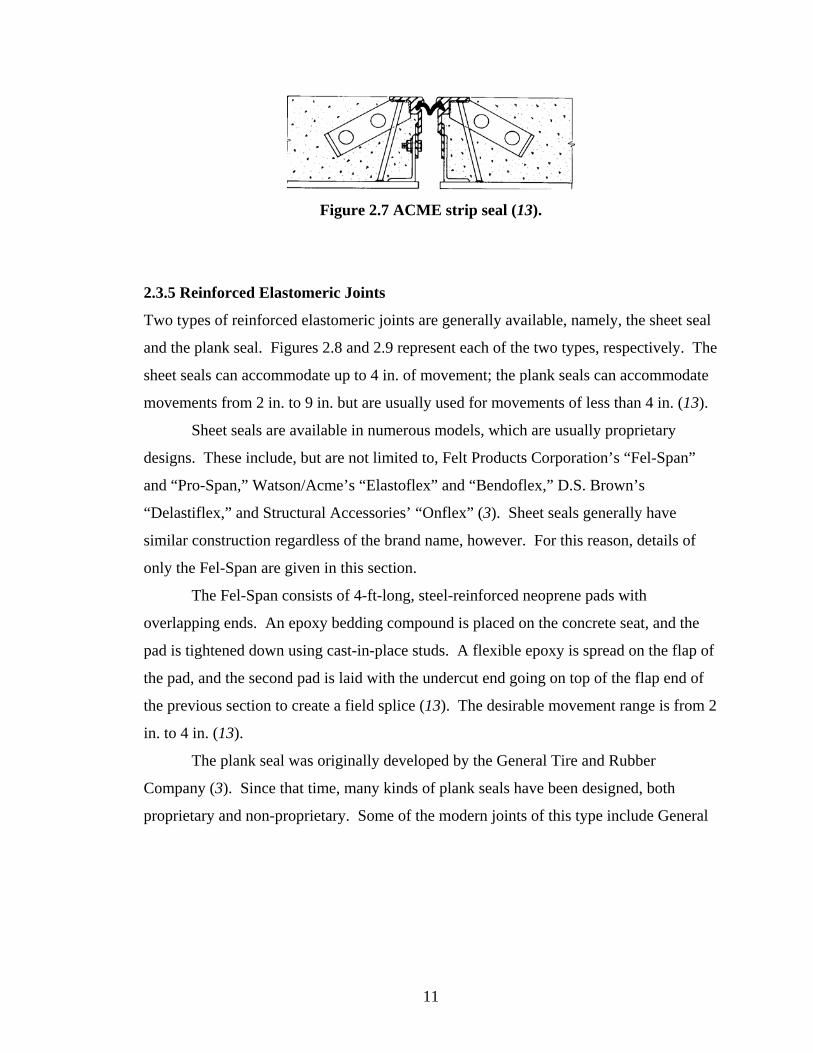
Figure 2.7 ACME strip seal (13).
2.3.5 Reinforced Elastomeric Joints
Two types of reinforced elastomeric joints are generally available, namely, the sheet seal
and the plank seal. Figures 2.8 and 2.9 represent each of the two types, respectively. The
sheet seals can accommodate up to 4 in. of movement; the plank seals can accommodate
movements from 2 in. to 9 in. but are usually used for movements of less than 4 in. (13).
Sheet seals are available in numerous models, which are usually proprietary
designs. These include, but are not limited to, Felt Products Corporation’s “Fel-Span”
and “Pro-Span,” Watson/Acme’s “Elastoflex” and “Bendoflex,” D.S. Brown’s
“Delastiflex,” and Structural Accessories’ “Onflex” (3). Sheet seals generally have
similar construction regardless of the brand name, however. For this reason, details of
only the Fel-Span are given in this section.
The Fel-Span consists of 4-ft-long, steel-reinforced neoprene pads with
overlapping ends. An epoxy bedding compound is placed on the concrete seat, and the
pad is tightened down using cast-in-place studs. A flexible epoxy is spread on the flap of
the pad, and the second pad is laid with the undercut end going on top of the flap end of
the previous section to create a field splice (13). The desirable movement range is from 2
in. to 4 in. (13).
The plank seal was originally developed by the General Tire and Rubber
Company (3). Since that time, many kinds of plank seals have been designed, both
proprietary and non-proprietary. Some of the modern joints of this type include General
11

Figure 2.8 Fel Span T30 sheet seal (13).
Figure 2.9 Transflex 400A plank seal (13).
Tire’s “Transflex,” Watson/Acme’s “Waboflex,” and Royston’s “Unidam” (3). Details
of only the Transflex product are given in this section.
The Transflex joint consists of 6-ft-long, metal-reinforced neoprene pads with
tongue-and-groove ends. A sealant is spread on the concrete seat in the non-movable
portion of the pad, and the pad is bolted down using cast-in-place studs. A flexible epoxy
is spread on the tongue-and-groove section, and the second pad is jacked in the transverse
direction against the previous pad and bolted down to construct a field splice. The stud
wells are sealed with a molded polychloroprene plug (13). The desirable movement
range is from 2 in. to 6.5 in. (13).
Regardless of the type of reinforced elastomeric joint used, reports state that the
most important factor contributing to the success of the joint is proper installation (14).
Contractors should closely follow the instructions provided by the manufacturer to
maximize joint service life.
12
2.3.6 Modular Elastomeric Joints
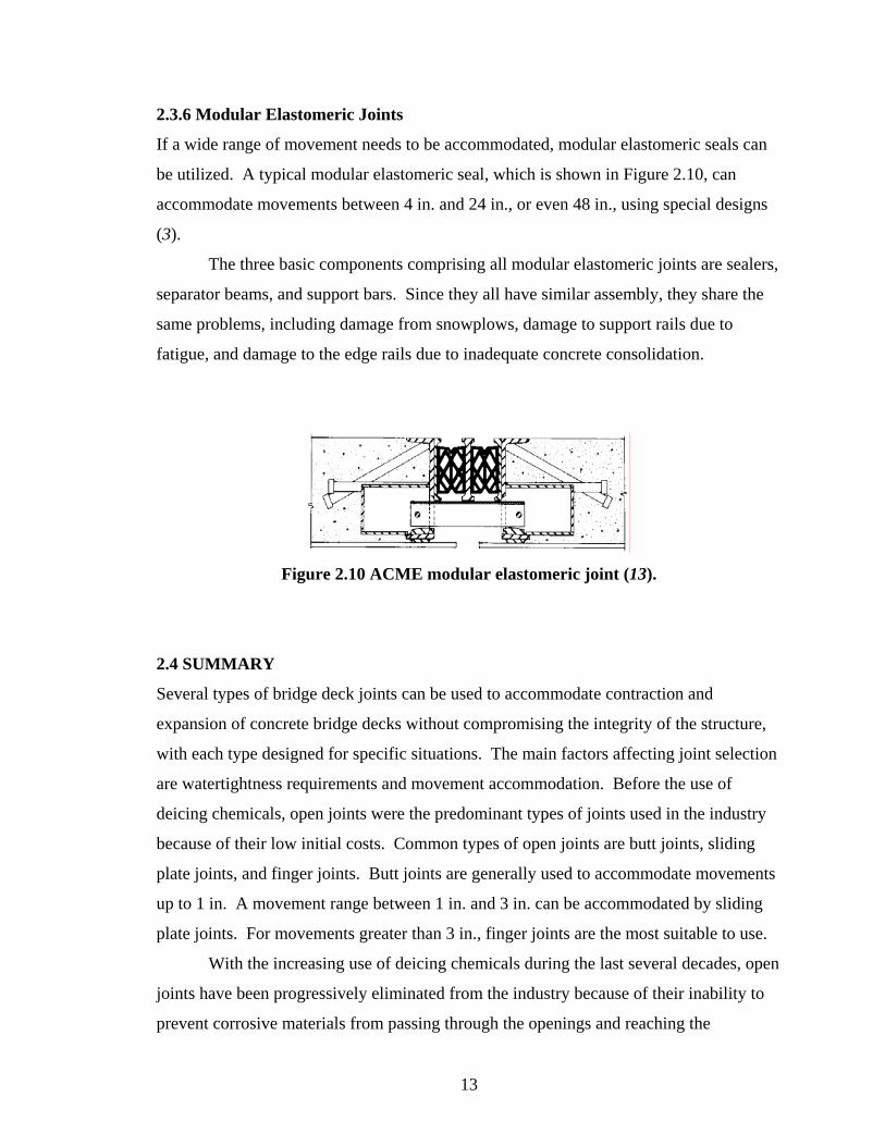
If a wide range of movement needs to be accommodated, modular elastomeric seals can
be utilized. A typical modular elastomeric seal, which is shown in Figure 2.10, can
accommodate movements between 4 in. and 24 in., or even 48 in., using special designs
(3).
The three basic components comprising all modular elastomeric joints are sealers,
separator beams, and support bars. Since they all have similar assembly, they share the
same problems, including damage from snowplows, damage to support rails due to
fatigue, and damage to the edge rails due to inadequate concrete consolidation.
Figure 2.10 ACME modular elastomeric joint (13).
2.4 SUMMARY
Several types of bridge deck joints can be used to accommodate contraction and
expansion of concrete bridge decks without compromising the integrity of the structure,
with each type designed for specific situations. The main factors affecting joint selection
are watertightness requirements and movement accommodation. Before the use of
deicing chemicals, open joints were the predominant types of joints used in the industry
because of their low initial costs. Common types of open joints are butt joints, sliding
plate joints, and finger joints. Butt joints are generally used to accommodate movements
up to 1 in. A movement range between 1 in. and 3 in. can be accommodated by sliding
plate joints. For movements greater than 3 in., finger joints are the most suitable to use.
With the increasing use of deicing chemicals during the last several decades, open
joints have been progressively eliminated from the industry because of their inability to
prevent corrosive materials from passing through the openings and reaching the
13

substructure elements. Indeed, the use of open joints was shown to be a major factor
shortening the service lives of bridges. Bridge designers therefore began to require the
use of closed joints to seal the openings. Six types of closed joints are typically used in
modern bridges. Among the six types, poured seals can accommodate movements up to
only 0.25 in. Asphalt plug seals and compression seals can accommodate movements up
to 2 in., while strip seals are used for movements up to 4 in. Sheet seals and planks seals
can be used when movements are up to 4 in. Modular elastomeric seals accommodate
movements from 4 in. to 24 in. and occasionally up to 48 in.
Joint service life can be maximized through utilization of correct construction
practices. Proper installation is the most significant factor contributing to joint
performance. Also, careful determination of the expected deck movements and informed
selection of the types of joints for use can increase the overall bridge life.
14
CHAPTER 3
PERFORMANCE EVALUATIONS OF BRIDGE DECK JOINTS
3.1 PERFORMANCE HISTORY
As stated in Chapter 2, open bridge deck joints are prone to cause concrete deck
deterioration and corrosion of reinforcing bars and substructures by allowing water,
debris, and deicing chemicals to pass through the joint openings. Approximately four
decades ago, these problems attracted the attention of bridge engineers and maintenance
crews, who began searching for bridge deck joints that could seal the openings and
ultimately remedy the deterioration and corrosion problems associated with open joints
(15). The ability of a bridge deck joint to remain watertight became the most dominant
factor in measuring joint performance (4).
The first closed joint was used as early as 1914 (16). The joint, as shown in
Figure 3.1, consisted of a flexible strip of copper sheet metal for spanning the opening
and a sealing compound for filling the gap. Very soon transportation agencies found that
the method was inefficient and required frequent maintenance (16).
In 1936, the B.F. Goodrich Industrial Products Company invented a sealing
element having a hollow section. Although this sealing element had marginally
improved success over the previous joint, modifications and improvements were still
needed (16). In 1960, the first compression seal, as shown in Figure 3.2, was developed
by the ACME Highway Product Corporation (16).
In time, many other proprietary deck joints were also produced and installed.
Being used for the first time, however, the joints lacked performance histories. For this
reason, state DOTs and universities set up evaluation programs to assess the performance
of the newly installed joints. In performing the assessments, they specifically sought to
identify the types of joints they should continue to use.
15
Figure 3.1 Design of first closed joint (16).
Figure 3.2 Design of first compression seal (16).
Eleven reports generated from these joint evaluations were identified in the
literature and reviewed in this research. A summary of findings is given in this chapter.
Consistent with Chapter 2, compression seals, strip seals, reinforced elastomeric joints,
and modular elastomeric joints are discussed. In addition, the performance
characteristics of finger joints with drainage troughs and joints with elastomeric nosing
are addressed.
16
3.2 COMPRESSION SEALS
Compression seals without armor steel angles were first used in approximately 1960 (16).
Soon afterwards, bridge engineers and maintenance crews realized that the unprotected
concrete adjacent to the openings spalled quite rapidly due to the impacts of heavy traffic.
During the next 10 years, modifications were made to install armor steel angles adjacent
to the seals. Among the eleven evaluations identified in the literature review in this
research, eight agencies evaluated the condition of a total of 519 in-service compression
seals between the years 1980 and 1990 (4, 15, 16, 17, 18, 19, 20, 21). Each inspected
compression seal was installed with armor steel angles.
Compression seals can generally be classified as cellular or neoprene (17).
Cellular compression seals are used primarily at the joint between the bridge deck and the
approach slab. At this location, approach slab movement and settlement are the main
sources of problems, which include debris accumulation, damaged armor angles and
anchorages, concrete spalling, and joint leakage (17). In spite of these problems,
however, the cellular compression seal is probably the best kind of seal for this location
because of its comparatively low cost.
Neoprene compression seals received very good ratings in overall performance.
Agencies in both Colorado and Ohio reported that the neoprene compression seals
performed the best, with only minor leakage problems, among all the joints used (16, 18).
The Colorado DOT continues to use the neoprene compression seal for movements less
than 2 in. because of its durability and low cost. Researchers reported that one of the key
advantages of neoprene compression seals is their ease of installation, although this
observation does not imply that correct installation procedures can be neglected. Indeed,
the Pennsylvania, Maine, and Arizona DOTs reported that problems with their neoprene
compression seals were associated with poor construction workmanship (4, 15, 19). For
example, the seals leaked due to being twisted while they were pressed into place, and the
armor steel angles became loose under heavy traffic loads because of inadequate concrete
consolidation under and around the armor steel angles.
Even though compression seals are not very susceptible to debris accumulation
and snowplow damage, careless installation can increase the vulnerability of the seals to
these types of damage mechanisms. For example, if the compression seals are set too far
17
below the riding surface, debris can easily accumulate on the seals. The incompressible
debris can then hinder the seals from expanding and contracting. The Nebraska,
Arkansas, and Maryland DOTs observed serious problems of this kind on some of their
compression seals (17, 20, 21).
On the other hand, if the compression seals are installed above the roadway
surface, the seals can be damaged or torn by snowplows and traffic. When the
compression seals are damaged or torn, the seals become leaky and thus lose their
watertightness function. Both the Arizona and Maryland DOTs reported that some
compression seals in their jurisdictions were damaged by snowplows to such a degree
that the seals needed to be replaced (19, 21).
3.3 STRIP SEALS
Many of the strip seals are proprietary products. The types of strip seals reviewed in this
research include the ACME Strip Seal, Wabo-Maurer Strip Seal, and Delastiflex MT
Strip Seal. In the literature review conducted in his research, only six reports discussing
strip seals could be identified. Among all the evaluations, a total of 206 strip seals were
inspected by six agencies during the period between 1980 and 1990 (4, 13, 15, 16, 18,
20).
The ACME and Wabo-Maurer strip seals received fair to good ratings by
inspectors, except that the Arkansas DOT had some problems associated with poor
construction workmanship and manufacturing defects. Both the Pennsylvania and
Colorado DOTs stated that they would continue to use strip seals for accommodating
movements less than 4 in. (4, 18). The only problem the Colorado DOT observed with
the strip seals was that the neoprene membranes were very difficult to slip into the
grooves of the side rails; however, if the neoprene membranes were correctly installed,
the seals exhibited a very high degree of watertightness. The Pennsylvania DOT reported
that they would continue to use strip seals for movements less than 4 in. because the seals
were cost effective. The only problems the Pennsylvania DOT encountered were very
minor, such as noise being produced when traffic crossed the joints, small amounts of
leakage, and debris accumulation (4).
18
The ACME and Wabo-Maurer strip seals are the standard joints in Ohio for
movements less than 4 in. (16). The Ohio DOT inspected 34 strip seals throughout the
state and found that they were in excellent condition. The strip seals had a very high
degree of watertightness and very good anchorage with only minimal surface damage.
The Maine DOT had both the ACME and Wabo-Maurer strip seals on their
inspection list as well. The ACME strip seals performed well in general, with problems
limited to minor debris accumulation and leakage, for example, that did not prevent the
seals from functioning properly. However, periodic maintenance of the seals was
necessary; otherwise, the accumulated incompressible debris would tear the neoprene
membranes when heavy traffic traversed the joints (15). The two inspected Wabo-
Maurer strip seals in Maine had failed. The failure was not related to the neoprene
membranes or the side rails, however. Instead, the highway approaches were not paved
during the construction phase, and heavy traffic carried gravel onto the seals, causing the
seals to be pulled out of the grooves.
The Arkansas DOT, unlike others, had negative experience with using strip seals.
They evaluated 26 ACME strips seals and 16 Wabo-Maurer strip seals. Inspectors
reported that debris accumulation was severe. In fact, the rate of debris accumulation
was so rapid that cleaning was not economically feasible (20). Also, inspectors reported
that approximately half of the joints had locations where the neoprene membranes were
pulled out of the grooves to an extent that the seals were no longer watertight.
The Michigan DOT was the only agency that reported experience using the
Delastiflex MT Strip Seals. Comments given by its inspectors were negative. The major
concern was that the seals were very susceptible to snowplow damage even though they
were set below the riding surface (13). Oftentimes the neoprene membranes were pulled
out of the grooves in the side rails. Damage to the neoprene membranes by snowplows
progressed with increasing length of service. When the neoprene membranes detached
from the grooves, the seals would completely lose their watertightness.
19
3.4 REINFORCED ELASTOMERIC JOINTS
As with strip seals, most of the reinforced elastomeric joints are proprietary products.
They are designed to accommodate movements up to 4 in. Among the eleven reports
reviewed, nine of them included reinforced elastomeric joints. A cumulative total of 616
joints were installed and inspected by the nine agencies. The most widely used
reinforced elastomeric joints are Fel Span, Transflex, and Waboflex.
According to the reports, reinforced elastomeric joints provided more trouble than
benefit to transportation agencies participating in the evaluation program. Except for the
observation that the joints were effective at preventing debris from accumulating in the
joints, comments on the joints were all negative (4, 13, 15, 16, 17, 18, 21, 22, 23). The
Virginia DOT reported that the performance of their reinforced elastomeric joints was
worse than less expensive joints installed on similar bridges (22), and the Maine DOT
even considered their reinforced elastomeric joints to be a complete failure (15).
Of the 616 reinforced elastomeric joints inspected by the agencies, all except two
in Maryland were leaking extensively (21). The two Fel Span joints installed in
Maryland had been in service for only 2 years at the time of inspection. Also, the traffic
volume on the two Fel Span joints was considered to be light, whereas all the other
reinforced elastomeric joints were installed on heavily trafficked roads (21).
In most cases, the longitudinal butt joints between sections at the locations of field
splices were prone to extensive leakage. The Michigan and Nebraska DOTs and the
University of Cincinnati reported that leakage at the interface was serious and happened
very rapidly after the joints were installed, even though flexible epoxy sealants were used
(13, 16, 17). The recommended solution to this problem was to reduce the number of
field splices by carefully laying out the system during the design phase (13).
The interface between the pads and the concrete was another location where
leakage occurred. The leakage was most likely due to poor caulking used at the interface,
poorly shaped concrete surfaces with which the joint material was in contact, and/or
loosening anchor bolts that held the pads in contact with the top of the abutment and deck
slab (15). The specification for reinforced elastomeric joints was discontinued in Maine
due to the associated leakage problems and relatively high costs of the joint (15).
20
The Pennsylvania, Nebraska, Maryland, and Virginia DOTs reported that the
reinforced elastomeric joints were difficult and expensive to install and maintain (4, 17,
21, 22). Because of the difficulty to install them correctly, the joints are often misaligned
horizontally and/or vertically. Serious leakage occurred at the misaligned areas on some
of the joints in Michigan and Kentucky (13, 23). Sometimes the misalignment was
caused by inaccurately constructed blockouts in the concrete.
In order to minimize corrosion of the bolts, bolt plugs are often used to seal the
bolt holes. Nowadays, the bolt holes are required to be filled with flexible epoxy.
However, when heavy traffic tranverses the joints, the flexible epoxy bolt plugs can
become loose. Consequently, the unfilled bolt holes become another source of leakage
and increase the probability of anchor bolt corrosion.
Unlike compression seals, reinforced elastomeric joints are apparently very
susceptible to snowplow damage. Except for the two joints installed in Maryland, all of
the other inspected reinforced elastomeric joints were damaged by snowplows regardless
of the quality of the installation. The Michigan DOT reported that the surfaces of the
pads were torn by snowplows so that the reinforcing metal was exposed, creating a
potential traffic hazard (13). Due to their many performance problems, difficulty of
installation, and high initial and replacement costs, reinforced elastomeric joints are not
typically recommended by engineers for modern bridge designs.
3.5 MODULAR ELASTOMERIC JOINTS
Modular elastomeric joints are essentially combinations of single compression seals or
strip seals (23). Greater numbers of single units can be used to accommodate larger
movements, typically greater than 4 in. Five agencies with experience using modular
elastomeric joints were identified in this research (4, 13, 15, 21, 23). A total of 200
modular joints were inspected and evaluated in these five states, including ACME,
Wabo-Maurer, and Delastiflex DL modular joints.
The ACME modular joint is available in two models, namely the ACME-ACMA
and ACME-BETA. The latter one is a modification of the former one. They are both
constructed using a series of single compression seals. Even though the ACME-BETA
21
modular joints are newer than the ACME-ACMA modular joints, some agencies such as
the Michigan and Kentucky DOTs are still using the ACME-ACMA product. Both
DOTs encountered very similar problems with the performance of this model, with
leakage between the compression seals and the steel supports as the first concern (13, 23).
In Michigan, some joints were found to be leaking over the entire joint length (13). The
other commonly observed problem was uneven compression of the neoprene modules.
The Maine and Maryland DOTs used both the ACME-ACMA and ACME-BETA
modular joints, but their ratings were quite different. The Maine DOT reported that the
performance of ACME-ACMA modular joints was poor, while the Maryland DOT said
that they performed well (15, 21). The joints in Maine were installed in accordance with
the manufacturer’s recommendations, but they were destroyed by traffic. The inspectors
did not know the cause of the poor durability. In Maryland, the joints were in good
condition with no snowplow or other damage. Comments on the ACME-BETA modular
joints were also different between the two DOTs, except that both reported that debris
accumulated in the joints. The Maine DOT reported that the joints were noisy under
traffic, while the Maryland DOT found no signs of any loose parts that might potentially
cause a noise problem (15, 21).
While the ACME joints received mixed reviews, the Wabo-Maurer modular joints
were all consistently given similar good ratings by agencies from Pennsylvania,
Maryland, and Kentucky. None of the agencies found evidence of leakage. They also
observed that no cuts or other damage occurred to the joints if the joints were recessed
between 0.125 in. and 0.25 in. below the riding surface (4, 21, 23). However, the
University of Kentucky reported that if the joints were set too far below the riding
surface, debris would accumulate in the cavity. If too much debris accumulates in the
joints, the probability of the modules being punctured increases. Researchers also
observed that as the number of single strip seals increased, vertical misalignment of the
support bars became problematic. Consequently, noise and ride discomfort were
produced, and uneven compression of the neoprene modules also occurred (23).
As with the Delastiflex MT strip seals, the Delastiflex DL modular joints did not
receive good ratings (4, 13). Evaluations were performed on eight Delastiflex DL
modular joints, among which three were evaluated by the Pennsylvania DOT and the
22
other five by the Michigan DOT. The greatest concern was that the Delastiflex DL
modular joints were very susceptible to snowplow damage (4, 13). Some neoprene
materials had been damaged so severely that they needed to be replaced. However, the
replacement was no less resistant to snowplow damage due to its equally high elevation
above the deck surface (13). The excessive exposure of neoprene material surfaces had
made the joints unsuitable for installation in areas using snowplows. In many cases,
Delastiflex DL modular joints were found to be leaky soon after installation. Due to the
poor performance of these joints, their installation difficulty, and their high initial cost,
the Michigan DOT decided to stop using Delastiflex DL modular joints after the
evaluation.
When modular joints were invented, designers were desirous to replace
conventional finger joints. Unfortunately, however, researchers reported, “Experience
with these systems shows that, while some of these expensive systems have performed
fairly well, most have had problems no less troublesome than those they were supposed
to eliminate when using the conventional finger dam systems” (4). Many transportation
agencies have therefore returned to using finger joints, placing more emphasis on
drainage troughs (2). For this reason, reports on the performance of finger joints with
troughs were also reviewed in this study. A summary is given in the following section.
3.6 FINGER JOINTS WITH TROUGHS
Finger joints were designed to accommodate movements greater than 3 in. (2). Among
the eleven reports reviewed in this research, only three, which were authored by the
Maine, Arkansas, and Pennsylvania DOTs, reported on the performance of finger joints.
These agencies had a total of 41 finger joints in service within their jurisdictions. Most
of the ratings of the 41 joints were good; the few low ratings were due to poor
construction.
The Maine DOT evaluated four of their finger joints, and all four joints performed
well. The joints had been in service from 6 to 22 years. One maintenance manager
remarked that this type of joint is the best in service (15). On structures with large skews,
the heavy finger joints were observed to keep the structure in alignment; the movement of
23
the structure destroyed other types of joints (15). While many other types of joints were
susceptible to snowplow damage, finger joints appeared to be very durable relative to
snowplow damage. The finger joints also fulfilled one of the main purposes and
functions of bridge deck joints by providing smooth transitions across deck slabs in terms
of ride quality (15). The only concern the Maine DOT had with finger joints was ice
build-up in the troughs. The built-up ice would restrict expansion movements. No
suggestion on how to prevent ice from building up in the troughs was provided, however.
The Arkansas DOT evaluated 15 finger joints that had been in service from 6 to
13 years (20). The report written by the inspector was simple, but clear. The report
stated that finger joints with neoprene or metal gutters provided the best performance
(20). The watertightness performance rating of the finger joints with troughs was in most
cases excellent. The only problem with finger joints reported by the Arkansas DOT was
debris accumulation (20).
The Pennsylvania DOT evaluated 22 finger joints that had been in service from 1
to 18 years (4). The report stated that the 22 finger joints had average performance
ratings higher than the ACME modular joints, Delastiflex DL modular joints, and Wabo-
Maurer modular joints (4). Problems the Pennsylvania DOT had with finger joints were
mostly due to poor construction. Horizontal misalignment during construction caused the
fingers to jam when the joint closed due to deck expansion, while vertical misalignment
caused poor ride quality, noise, and sometimes bending or breakage of some fingers. The
other problem related to poor construction was blockage of the joints by debris
accumulation. They observed that this problem arose when the trough did not have
sufficient slope to drain the contaminated water and flush the loose debris before it had a
chance to accumulate and harden. The Arkansas DOT stated, “When a finger joint had a
trough sloping at eight percent, there was no debris accumulation six years after
placement, but when the trough had a slope of one percent it was filled with debris in six
months” (20). The problem of debris accumulation can also be alleviated by periodic
maintenance. All three DOTs said that the neoprene or metal troughs generally require
cleaning on an annual basis (4, 15, 20).
The Pennsylvania DOT also observed that the fingers in the finger joints could
sometimes be bent or even broken under the continuous pounding of heavy traffic (4).
24
They suggested that fingers should be designed with sufficient tensile strength, well
aligned, and properly anchored during construction to minimize bending and breaking.
Even though the Pennsylvania DOT had encountered the problems with finger
joints mentioned above, they continued to use finger joints for movements over 4 in.
because, based on a comparison of initial costs and general performance, finger joints
were the most cost effective.
Based on the reports given by the three agencies on the performance of finger
joints, the joints should perform according to design and better than most types of
modular joints if the joints and the trough underneath are installed correctly, periodic
maintenance is performed at least once a year, and ice is prevented from building up in
the troughs.
3.7 ELASTOMERIC NOSING MATERIALS
While steel-armored bridge deck joints function well at times, steel angles can cause
performance problems. Some transportation agencies tried to replace the steel angles by
using elastomeric concrete, especially after 1980. During this period of time, elastomer
technology was developing rapidly. The Florida DOT conducted a 2-year bridge deck
joint evaluation program that began in the spring of 1993 and concluded in December of
1995 (24). The purpose of the program was to assist bridge engineers in Florida with
selecting expansion joint systems. Ratings of the selected joints were based on four
components: performance evaluation, load test evaluation, installation and maintenance
evaluation, and overall product evaluation by the state materials office. The test included
joint sealants, compression seals, strip seals, and buried joint systems installed with steel
armor or elastomeric nosing. The following are the joint sealants or systems evaluated in
the program:
1. Chemcrete 1000 Expansion Joint System
2. Delcrete Elastomeric Concrete/Steelflex Strip Seal System
3. Dow Corning 902 RCS Joint Sealant
4. X.J.S. Expansion Joint System
25

5. Ceva 250 Joint System
6. Ceva 300 Joint System
7. Evazote 380 ESP
8. Jeene Structural Sealing Joint System (PC35)
9. Jeene Structural Sealing Joint System (PC92M)
10. Sylcrete 10 Minute Joint Sealant
11. Resurf IV
12. Expandex Buried Joint System
13. Wabocrete ACM Expansion Joint
14. Koch 2000 SL Bridge Joint Sealant
15. Koch BJS Joint System
16. Flexcon 2000 Joint Sealing System
17. Techstar Elastomeric Strip Seal
Among these 17 joint sealants and systems in the project, only the Koch BJS and
Expandex Buried Joint System are asphalt plug joints. Four of the products are sealants,
including the Dow Corning 902 RCS Joint Sealant, Evazote 380 ESP, Koch 2000 SL
Bridge Joint Sealant, and Sylcrete 10-Minute Joint Sealant. The other ten products are
complete joint systems.
From the results of the 2-year evaluation program, the following joint sealants and
joint systems were approved for use in Florida:
1. Dow Corning 902 RCS Joint Sealant (poured silicone seal with armored edges)
2. X.J.S. Expansion Joint System (poured silicone seal with polymer blockout)
3. Ceva 300 Joint System (closed cell compression seal with armored edges)
4. Expandex Buried Joint System
5. Koch BJS Joint System
6. Delcrete Elastomeric Concrete/Steelflex Strip Seal System (strip seal with
polymer blockout)
7. Jenne Structural Seal (seal only, not the system).
26
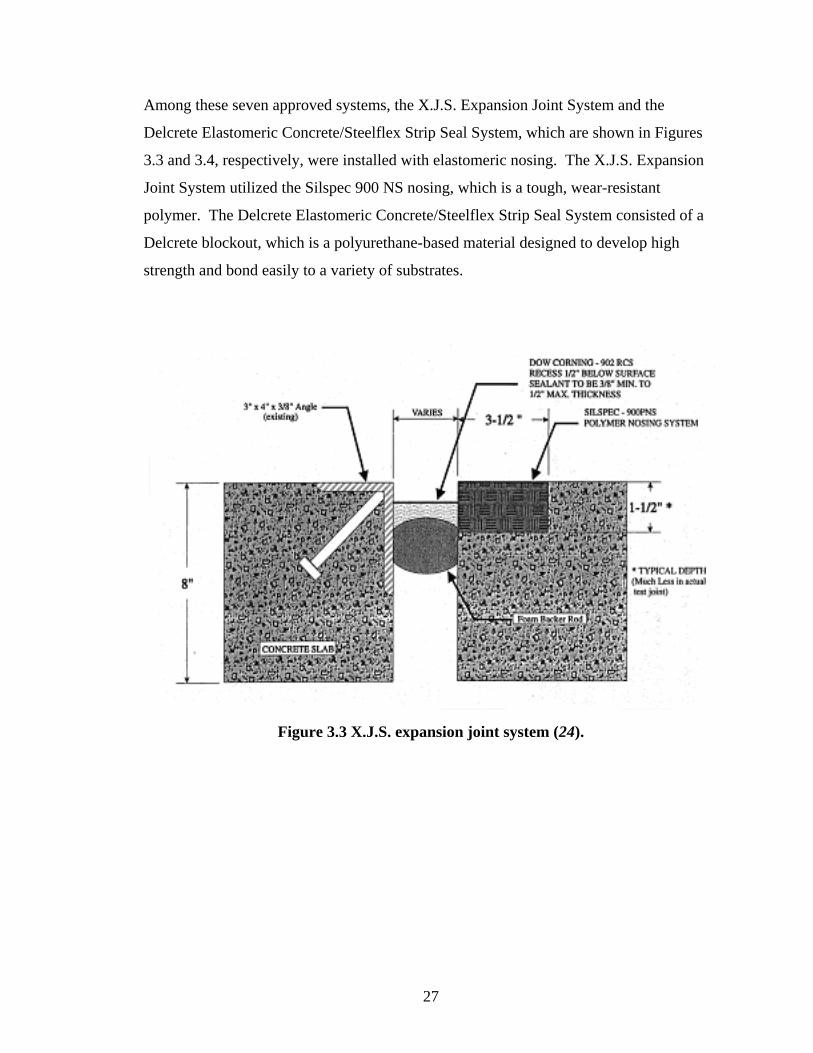
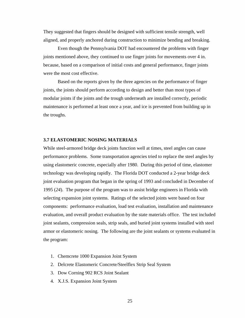
Among these seven approved systems, the X.J.S. Expansion Joint System and the
Delcrete Elastomeric Concrete/Steelflex Strip Seal System, which are shown in Figures
3.3 and 3.4, respectively, were installed with elastomeric nosing. The X.J.S. Expansion
Joint System utilized the Silspec 900 NS nosing, which is a tough, wear-resistant
polymer. The Delcrete Elastomeric Concrete/Steelflex Strip Seal System consisted of a
Delcrete blockout, which is a polyurethane-based material designed to develop high
strength and bond easily to a variety of substrates.
Figure 3.3 X.J.S. expansion joint system (24).
27
Figure 3.4 Delcrete elastomeric concrete/Steelflex strip seal system (24).
3.8 SUMMARY
Concrete deck deterioration and corrosion of reinforcing bars and substructures due to the
intrusion of water, debris, and deicing chemicals are significant factors in overall bridge
performance. In response to these issues, closed joints have been increasingly used to
replace conventional open joints in order to seal deck openings. Watertightness is now
widely recognized as an important joint characteristic.
Among the three types of closed joints commonly used in the United States for
accommodating small movements, reinforced elastomeric joints are not recommended by
most of the agencies who had experience with using them. Reinforced elastomeric joints
are susceptible to snowplow damage, making them unsuitable for locations where
snowplows are used. These joints are also difficult and expensive to install and maintain.
They are not cost effective since the performance of these joints is generally worse than
the performance of other functionally similar joints that are less expensive. All of these
28
shortcomings of the reinforced elastomeric joints caused them to be eliminated from
common use.
For movements less than 2 in., compression seals with armor steel angles are
recommended. The installation cost of compression seals is low compared to other types
of joints. They can be installed without significant difficulty; however, the installation
must be performed correctly to ensure good performance. During construction, concrete
around and under the armor steel angles must be adequately consolidated, and the seals
must not be twisted during installation.
Many agencies recommend continued use of strip seals for movements less than 4
in., except the Delastiflex MT model. This model is not recommended because it is very
susceptible to snowplow damage even if it is set below the riding surface. The other strip
seal models perform very well with only minor leakage problems. As with compression
seals, care must be taken when installing the strip seals. Components most sensitive to
construction errors are the neoprene membranes and the grooves in the side rails. If the
neoprene membranes are not slipped into the grooves tightly, they can be detached by
snowplows or traffic very easily.
Modular elastomeric joints are designed to accommodate deck movements larger
than 4 in. However, they can exhibit numerous problems, including leakage, damage
from snowplows, damage to the neoprene sealant material, and damage to the supports.
Among the three common types of modular joints, the Delastiflex DL modular joints
perform the worst. Characterized by numerous problems, modular joints do not presently
appeal to bridge engineers. Until modular elastomeric joints can be improved adequately,
finger joints are the type most bridge engineers prefer to use for large movements. If
finger joints are installed carefully, maintained periodically, and provided with drainage
troughs having sufficient slope, they can provide high levels of performance for many
years.
Steel armor angles often become dislodged and thus become leaky and hazardous
to traffic. To avoid these problems, some transportation agencies utilize elastomeric
concrete nosing instead of armor angles. The evaluation performed by the Florida DOT
suggested that the X.J.S. Expansion Joint System with the Silspec 900 NS nosing and the
29

Delcrete Elastomeric Concrete/Steelflex Strip Seal System with the Delcrete blockout can
be successfully used to replace conventional joints with steel armor angles.
30
CHAPTER 4
UDOT EXPERIMENTAL JOINT EVALUATIONS
4.1 IN-HOUSE UDOT RESEARCH
According to information provided by UDOT, only five in-house experiments on bridge
deck joint systems, which were performed between 1992 and 1999, have been recorded.
Without any exceptions in these experiments, UDOT endeavored to identify new joint
products that met required standards while attempting to replace failed systems.
However, not every new product performed satisfactorily. Even though some of the new
products performed well, only a few were later included in the UDOT standard
specification for bridge deck joints.
The following sections present a brief summary of each of the five joint products
evaluated by UDOT, including the Koch-Bestway bridge joint repair system, the Dow
Corning 902 RCS silicone joint sealant, the Silspec 900 PNS polymer nosing system with
Dow Corning 902 RCS silicone joint sealant, the Sikaflex 15LM low-modulus
elastomeric polyurethane joint sealant, and the Flexcon 2000 joint sealant system with
Flexcon A/C nosing.
4.2 KOCH-BESTWAY BRIDGE JOINT REPAIR SYSTEM
The first joint on the west abutment of structure F-298 located eastbound on Interstate 80
at Parley’s Summit failed and needed to be replaced. A Koch-Bestway bridge joint repair
system was installed by Koch-Bestway of Greeley, Colorado, on April 2, 1992. The new
joint system required 2 days to install and was inspected once a year for 3 years after
installation.
31
The first inspection was made in April of 1993, by which time failure had already
occurred. The supplier of the joint requested that another joint be installed and claimed
that the previous installation was performed incorrectly. The supplier was allowed to
replace the failed joint at no cost to UDOT outside of traffic control. The new joint was
installed on July 12, 1993, and it was also inspected once a year. In July of 1995, the
inspectors agreed that the joint was performing well enough to be approved.
4.3 DOW CORNING SILICONE JOINT SEALANT
When the original joint on the structure located 1 mile east of Interstate 15 on State Route
175 failed, a Dow Corning 902 RCS silicone joint sealant was installed in conjunction
with a large backer rod as a replacement. This new joint seal material was evaluated for
adhesion and durability on 6-month intervals to investigate its potential utility for future
bridge joint repairs.
On May 11, 1992, UDOT evaluated this silicone joint repair and found that the
material had been pulled away from the receptacle gland. Because the joint system failed
in less than 6 months, the inspector recommended that UDOT continue to entertain other
bridge deck joint companies.
4.4 SILSPEC POLYMER NOSING SYSTEM WITH DOW CORNING SILICONE
JOINT SEALANT
The eastbound lane of structure C-629 on Interstate 215 at mile post (MP) 16.69 required
bridge deck joint repairs in 1993. The joint system used to repair the failed one consisted
of the Silspec 900 PNS polymer nosing system with the Dow Corning 902 RCS silicone
joint sealant. Visual inspections of both materials were performed once every 3 months
in the first year and once every 6 months in the second year. During each inspection,
joint leakage; bonding between the nosing material, substrates, and joint sealant material;
distresses in the nosing material and silicone sealant; and overall performance of the
materials were observed.
32
Final inspection was performed on October 12, 1994, by UDOT. The joint
system showed no signs of leakage, the bonding of the Silspec 900 PNS polymer nosing
to the concrete substrate and the bonding of the joint sealant material to the nosing
material “looked good,” the nosing material showed no signs of distress, the joint sealant
material was soft and pliable, and the overall performance of the materials was good.
Since this repair joint system was successful, it was approved for future use on similar
structures.
4.5 SIKAFLEX LOW-MODULUS ELASTOMERIC POLYURETHANE JOINT
SEALANT
Until 1994, the silicone joint sealant was the only joint system permitted in the UDOT
standard specification. Ten Sikaflex 15LM low-modulus elastomeric polyurethane joint
sealants, which were installed by Sika Corporation on October 12, 1994, on northbound
Interstate 15 at approximately MP 207.5, were evaluated to determine whether the
products could be added into the UDOT standard specification. The joints were
inspected every 6 months for at least 5 years. The performance of the new joints was
compared with the silicone joint sealants installed in the adjacent lane.
In September of 1997, only the third year of a 5-year guarantee, five of the ten
joints showed elongation failure, and the evaluation team agreed that the performance
would worsen through time since stretch marks in the joint seal material were already
present. This final evaluation suggested that these Sikaflex joint sealants could not be
approved for inclusion in the UDOT standard specification.
4.6 FLEXCON 2000 JOINT SEALANT SYSTEM WITH FLEXCON A/C NOSING
A Flexcon 2000 joint sealant system with Flexcon A/C nosing material was used to
replace a failed joint system on structure C-745 over the Green River along State Route
45 at MP 32.74. After the installation, visual inspection of the materials was performed
once every 3 months during the first year and once every 6 months during the second
year.
33

After two inspections had been performed, the UDOT Structures Division
reported that no signs of failure were observed in either evaluation and decided that the
Flexcon 2000 joint sealant system was an acceptable bridge joint repair system for future
use on similar structures.
4.7 SUMMARY
Among the five bridge deck joint products evaluated by UDOT between 1992 and 1999,
three performed satisfactorily and were permitted for future use on similar structures.
The three approved systems were the Koch-Bestway bridge joint repair system, the
Silspec 900 PNS polymer nosing system with the Dow Corning 902 RCS silicone joint
sealant, and the Flexcon 2000 joint sealant system with Flexcon A/C nosing material.
Outside of this information, other conclusions related to the present research objective
could not be drawn from the reports since they were unclearly written, inconsistent, and
lacked detailed information relevant to the experimentation.
In order to properly document experiments for future reference, UDOT should
include the ADT of the bridges during the year of testing, the anticipated joint
movements that need to be accommodated, the reason for repairing or replacing the
existing joints, and the procedures utilized for selecting specific products for evaluation.
Furthermore, the contact information of the person who was in charge of the
rehabilitation project, as well as the manufacturer representative who installed the joint,
should also be given for future inquiry. With this additional information, engineers
making future decisions about joint rehabilitations for similar structures can refer back to
the reports and find meaningful data.
Besides increasing the amount of engineering data provided in UDOT reports
about the bridges and experimental products, a consistent evaluation program should also
be established. For example, inspections of experimental joints should follow a
standardized checklist of relevant performance characteristics. Among these
requirements could be debris accumulation, adhesion and cohesion of the joint materials,
condition of anchorages and/or header materials, watertightness of the joints, condition of
the concrete edges of the deck joints, deterioration of substructures, riding quality, noise
34

level under travel, and general appearance of the joints, for example. With a consistent
evaluation program, UDOT should be able to achieve greater objectivity and reliability in
the process of approving new joint products for inclusion in the UDOT standard
specification.
35

36
CHAPTER 5
STANDARD SPECIFICATIONS AND TESTS
5.1 SOURCES OF SPECIFICATIONS AND TESTS
Bridge deck joint companies often claim that their products are durable and can withstand
various traffic and environmental conditions. However, as described in Chapters 3 and 4,
many products perform unsatisfactorily and fail prematurely. Specifications and tests are
therefore necessary to assess the performance qualities of bridge deck joints.
Unfortunately, among all types of joints used today, only poured seals, compression
seals, and strip seals have such specifications and tests available for assessing and
controlling their characteristics. Even though specifications for poured seals are
described in the ASTM standards, results from research and laboratory testing show that
the specifications and test methods may not effectively identify poor sealants (7).
Therefore, some modifications to the test methods for poured seals have been
recommended by researchers. No studies on the effectiveness and accuracy of the
specifications and test methods for compression seals or strip seals were identified in the
literature; therefore, the tests outlined in the ASTM standards are apparently the only
sources available for evaluating these kinds of seals.
Adhesive lubricants are often used to facilitate the installation of both
compression seals and strip seals. The ASTM standards also describe tests designed to
evaluate whether the adhesive lubricants will function properly. The specifications for
poured seals, compression seals, strip seals, and adhesion lubricants are discussed in the
following sections.
37
5.2 POURED SEALS
Specifications and test methods for poured seals are not readily available in the ASTM
standards. The most relevant standard is ASTM C 719, Test Method for Adhesion and
Cohesion of Elastomeric Joint Sealants Under Cyclic Movement (Hockman Cycle).
However, this test method particularly addresses building seals and sealants, which have
less rigorous performance requirements, so inadequate poured seals may pass the test and
be mistakenly approved for installation on bridge decks. Therefore, in order to improve
performance predictions of poured seals, researchers have modified the test methods
based on the results of laboratory testing (7). The modifications are suitable for use in
states that have climates similar to the state of Wyoming. All recommendations are
based on a 0.5-in. sealant width (7). The proposed sealant evaluation process consists of
specimen preparation, sealant curing, and testing as described in the following sections.
Criteria for sealant selection are also discussed.
5.2.1 Specimen Preparation
The dimensions of mortar briquettes and sealant specimens should follow the
recommendations outlined in ASTM C 719. Cement should be Type III Portland Cement
conforming to ASTM C 150, Standard Specification for Portland Cement. Fine
aggregate should be sand conforming to ASTM C 33, Standard Specification for
Concrete Aggregates. The 3-in. by 2-in. by 1-in. mortar cubes should be cast in
accordance with ASTM D 1985, Standard Practice for Preparing Concrete Blocks for
Testing Sealant for Joints and Cracks. After casting, a dry diamond blade should be used
to saw the mortar cubes in half to a final dimension of 3 in. by 1 in. by 1 in. The use of a
dry diamond blade in this laboratory test replicates actual joint installation on a bridge
deck.
After the mortar briquettes are formed, they should be cleaned using pressurized
water to remove concrete dust and other debris. Then, both joint faces should be
sandblasted and cleaned with a blast of compressed air (7). When the briquettes are
completely dry, the two halves should then be sealed as described in ASTM C 719.
Whether a primer is used prior to sealing is dependent on the sealant manufacturers’
recommendations.
38
5.2.2 Sealant Curing
ASTM C 719 outlines the curing and conditioning environment for both single- and
multi-component sealants. Standard conditions in this test are defined as a temperature of
73.4 ± 3.6°F and a relative humidity of 50 ± 5 percent. For single-component sealants,
the curing period consists of 7 days at standard conditions, followed by 7 days at 100 ±
3.6°F and 95 percent relative humidity, followed by 7 days at standard conditions. Multi-
component sealants should be cured at standard conditions for 14 days only. After the
curing period, both the single- and multi-component sealants should be immersed in
distilled or deionized water for 7 days and then placed into a 158°F oven under
compression for 7 days.
The heat-aging process is designed to determine the amount of compression set a
sealant will experience. The more compression set a sealant experiences, the more strain
capacity it loses. Therefore, the curing and conditioning process specified in ASTM C
719 is necessary to determine whether the sealants can accommodate joint movements
during the hottest summer days. However, some test results show that the heat-aging
process will improve the adhesion strength of certain kinds of sealants. For this reason,
tests should also be performed on sealants that are cured in accordance with ASTM C
719, but with the water immersion and heat-aging steps omitted (25). Sealants without
heat aging are representative of installations in the fall (7). All the sealant specimens to
be cured without subjection to the water immersion and heat-aging steps should be placed
at standard conditions for 14 days after curing so that they can be tested with the sealants
that have experienced the water immersion and heat-aging processes at the same age on
the 35th day and the 28th day for single-component and multi-component sealants,
respectively.
In addition to the two curing and conditioning environments mentioned above,
single-component sealants should also be cured at standard conditions for 21 consecutive
days, followed by subjection to standard conditions for 14 days in order to be tested
together with other single-component sealants on the 35th day. Removal of the 7-day
period of elevated temperature conditions and humidity in this case is performed because
the curing time for most single-component sealants is mainly dependent on the amount of
moisture in the atmosphere. The curing condition in this testing scenario is intended to
39
simulate the curing of sealants in dry climatic areas, such as Utah, where longer curing
time is required than in humid areas (7).
5.2.3 Testing
The original test method specified in ASTM C 719 requires subjection of the sealant
specimens to compression and extension cycles; however, researchers observed that this
method is unable to accurately test the strain capacity of the field-molded bridge joint
sealants (7). The sealants should instead be subjected to pure tension until failure instead
of cyclic compressive and tensile strains. Tests should then be performed at two different
temperatures, the standard temperature as outlined in ASTM C 719 and –40°F (7). Three
specimens for each curing and conditioning environment described in the above
paragraph should be tested at each temperature.
5.2.4 Sealant Selection
Guidelines for sealant acceptance are based on sealant strain capacity (7). To evaluate
sealant strain capacity, results from the tension test on specimens cured in accordance
with ASTM C 719, including the water immersion and heat-aging steps, should be used.
The test conducted at –40°F represents the worst scenario, where the sealants are strained
to their maximum extension in the winter after experiencing compression set during the
summer. In order to pass, the sealant must exhibit a minimum of 100 percent strain
before failure.
To evaluate sealant adhesion strength, tension tests should be performed on
single-component sealant specimens cured for 21 days at standard conditions and on
multi-component sealants specimens cured for 14 days at standard conditions. As
mentioned earlier, specimens are not immersed in water nor heated in an oven because
heat aging may increase adhesion strength. Results from testing at standard conditions
and at –40°F should be used to determine the adhesion strength. In order to pass, a given
sealant must exhibit a minimum of 200 percent strain without detaching from the mortar
briquettes.
Researchers also suggest that the length of time for a sealant to cure should be
limited because the amount of time a lane needs to be closed is an important construction
40
issue. The time for a sealant to develop a top skin should be less than 6 hours, and the
time required from joint face preparation to trafficking should be limited to 24 hours (7).
5.3 COMPRESSION SEALS
Numerous performance characteristics for compression seals are described in the ASTM
standards. The particular document is ASTM D 3542, Standard Specification for
Preformed Polychloroprene Elastomeric Joint Seals for Bridges. The specification is
only applicable to seals in which the height exceeds 90 percent of the nominal width.
Material properties evaluated for qualifying compression seals for use in bridge joint
systems include recovery, compression-deflection properties, tensile strength, durometer
hardness, oven aging, oil swell, and ozone resistance. Brief explanations of the
corresponding tests are given in the following sections.
5.3.1 Recovery
Both high- and low-recovery tests are used to determine the degree of recovery of a
compression seal after it has been compressed to 50 percent of its nominal width for a
specific amount of time under extreme temperatures. The percentage of recovery should
be calculated using Equation 1:
100⋅=n
r
wwR (1)
where R = recovery, %
= recovered width, in. rw
= nominal width, in. nw
According to the test protocol, a total of six specimens are prepared by cutting
and buffing a sample of preformed seal. Two of them are used for the high-recovery test,
and the remaining four are used for the low-recovery test. Tooth-blade devices or
guillotine-type cutters cannot be used for specimen trimming because they eliminate
natural irregularities that affect the bonding between the sealant and the concrete face.
41
Also, when the samples are buffed, care should be taken so that the specimens are not
overheated.
Specimens should be deflected to 50 percent of their nominal width using the
assembly specified in Method B of ASTM D 395, Standard Test Methods for Rubber
Property—Compression Set. For the high-recovery test, two compressed specimens are
placed in an oven conforming to ASTM D 573, Standard Test Method for Rubber—
Deterioration in an Air Oven, for 70 hours. The oven should be capable of maintaining a
temperature of 212 ± 2°F. The specimens should not be preheated. After the test, the
compressive force is removed, and the specimens are allowed to recover at 73 ± 4°F for 1
hour before the recovered width is measured for calculation of the recovery. ASTM D
3542 requires 85 percent of high recovery.
According to ASTM D 3542, compression seals should be tested in two
conditions for the low-recovery test, 14 ± 2°F for 72 hours and –20 ± 2°F for 22 hours.
Two specimens are required to be tested under each of the two conditions. For each
condition, two compressed specimens are placed in a refrigerated box to maintain the
specified temperature. After the test, the compressive force is removed, and the
specimens are allowed to recover for 1 hour at the same temperature before the recovered
width is measured and the recovery is calculated. ASTM D 3542 requires 88 percent of
low recovery in tests performed at 14 ± 2°F and 83 percent at –20 ± 2°F.
5.3.2 Compression-Deflection Properties
The purpose of the compression-deflection test is to determine the movement range of a
compression seal. The results of the test are given in terms of Minimum Limit of
Compressibility (LC min) and Maximum Limit of Compressibility (LC max). Both the
LC min and LC max are expressed as percentages of the nominal width. LC min is
defined as the compressed width corresponding to a contact pressure of 3 psi. LC max is
defined as the compressed width corresponding to contact pressure of 35 psi.
Test specimens for the compression-deflection tests are prepared in the same way
as those for the high- and low-recovery tests. Forces required to compress the specimen
to LC min and LC max should be determined by multiplying the contact area by 3 psi and
35 psi, respectively. The forces should be applied to the specimens in accordance with
42
Method A of ASTM D 575, Standard Test Methods for Rubber Properties in
Compression, except that the rate of force application should be 0.5 ± 0.05 in./minute and
the use of sandpaper specified in the document should be omitted. During the course of
compression, the tendency of the top surface of the specimen to become horizontally
misaligned should be observed. If misalignment exceeds 0.25 in., the seal should be
rejected. The difference between LC min and LC max is the permissible range of
movement for the specimen.
5.3.3 Tensile Strength
Tensile strength and elongation at break are two important parameters in determining
whether seals will perform well in the field. The test method is explicitly detailed in
ASTM D 412, Standard Test Methods for Vulcanized Rubber and Thermoplastic
Elastomers—Tension.
The test specimens should be formed in the shape of a standard dumbbell using
Die C described in ASTM D 412 unless the flat sections of the seal are too small for Die
C. In this case, Die D may be used. A machine able to provide a uniform rate of grip
separation of 20 ± 2 in. should be used in the test. The test should be run at a temperature
of 73.4 ± 3.6°F, and the relative humidity should be maintained at 50 ± 5 percent
throughout the test if the material is affected by moisture. The specimens should be
placed under these conditions at least 24 hours before the test starts. For a compression
seal to pass the requirements of ASTM D 3542, it must exhibit a minimum tensile
strength of 2,000 psi and a minimum elongation at break of 250 percent.
5.3.4 Durometer Hardness
Indentation hardness of sealants should be tested by a Type A durometer as specified in
ASTM D 2240, Standard Test Method for Rubber Property—Durometer Hardness. The
test specimens should be at least 0.25-in. thick. This thickness may be obtained by a
composition of plied pieces. The surfaces of the specimen should be flat and parallel
over a sufficient area so that the presser foot is allowed to have a minimum 0.5-in.-
diameter contact area on the specimen. Also, the surfaces of the specimen should not be
43
rounded, uneven, or rough. ASTM D 3542 requires that sealants exhibit 55 ± 5 points of
hardness.
5.3.5 Oven Aging
The tensile and durometer hardness tests should also be conducted on specimens that are
placed in an oven at 212°F for 70 hours. Preparation of specimens is exactly the same as
mentioned in the sections given earlier for each test. After the specimens are heated for
70 hours, they are then tested for tensile strength and elongation at break in accordance
with ASTM D 412 and tested for durometer hardness in accordance with ASTM 2240. In
order to pass the test, sealants must not lose more than 20 percent of their tensile strength
or elongation at break and must not have an increase in hardness exceeding 10 points
compared to the results from tests under normal conditions.
5.3.6 Oil Swell
The oil swell test is used to determine the ability of sealant materials to withstand the
effect of liquids. The test method is detailed in ASTM D 471, Standard Test Method for
Rubber Property—Effect of Liquids. Unless otherwise specified, the specimens should
be prepared in accordance with the requirements of ASTM D 3182, Standard Practice for
Rubber—Materials, Equipment, and Procedures for Mixing Standard Compounds and
Preparing Standard Vulcanized Sheets, and D 3183, Standard Practice for Rubber—
Preparation of Pieces for Test Purposes from Products. The type of oil used in the test
should be ASTM Oil No. 3. The test should be conducted at 212°F for 70 hours. ASTM
D 3542 specifies that the sealant must not experience a weight increase greater than 45
percent.
5.3.7 Ozone Resistance
The ozone resistance test is used to estimate the resistance of sealant materials to
cracking when exposed to an atmosphere containing ozone. The test method is explained
in ASTM D 1149, Standard Test Method for Rubber Deterioration—Surface Ozone
Cracking in a Chamber. The specimens for the test should be prepared in accordance
with Method A of ASTM D 518, Standard Test Method for Rubber Deterioration—
44
Surface Cracking. The specimens should be cleaned with toluene to remove surface
contamination prior to testing. The prepared specimens should then be subjected to a
surface tensile strain of 20 percent in a chamber containing 300 parts per hundred million
(pphm) in air at 104°F for 70 hours. ASTM D 3542 specifies that sealants should exhibit
no cracks after the test. Specimens fail the test if cracking, splitting, or sticking occurs
during either the high- or low- recovery tests described earlier.
5.4 STRIP SEALS
Specifications for strip seals are described in ASTM D 5973, Standard Specification for
Elastomeric Strip Seals with Steel Locking Edge Rails Used in Expansion Joint Sealing.
The use of structural steel locking edge rails should conform to ASTM A 588, Standard
Specification for High-Strength Low-Alloy Structural Steel with 50 ksi [345 MPa]
Minimum Yield Point to 4-in. [100-mm] Thick; ASTM A 36, Standard Specification for
Carbon Structural Steel; ASTM A 572, Standard Specification for High-Strength Low-
Alloy Columbium-Vanadium Structural Steel; or as specified by the purchaser.
Many of the strip seal tests are the same as those mentioned in ASTM D 3542 for
compression seals, although a couple of tests specified in ASTM D 5973 are not
mentioned in D 3542. The tests that are excluded in ASTM D 5973 are the high- and
low-recovery tests and the compression-deflection test. Instead, a low-temperature
stiffening test and a compression-set test are included in ASTM D 5973. Therefore, the
following sections provide brief explanations of tests used to measure tensile strength,
durometer hardness, oven aging, oil swell, ozone resistance, low-temperature stiffening,
and compression set for strip seal materials. Details concerning specimen preparation are
not given if the method is the same as one previously described for compression seals.
5.4.1 Tensile Strength
Tensile strength and elongation at break for strip seal materials should be tested in
accordance with ASTM D 412. ASTM D 5973 requires that strip seal materials exhibit a
minimum tensile strength of 2,000 psi and a minimum elongation at break of 250 percent.
45
5.4.2 Durometer Hardness
Indentation hardness of sealants should be tested by a Type A durometer as specified in
ASTM D 2240. ASTM D 3542 requires that strip seal materials exhibit 55 to 65 points
of hardness.
5.4.3 Oven Aging
As with compression seal materials, the tensile strength, elongation at break, and
durometer hardness of strip seal materials should also be tested after the materials have
been conditioned in an oven at 212°F. After the specimens are heated for 70 hours, the
specimens are then tested for tensile strength and elongation at break in accordance with
ASTM D 412 and for durometer hardness in accordance with ASTM D 2240.
For a strip seal material to pass the tests, the material must not lose more than 20
percent of its tensile strength or elongation at break and must not have an increase in
hardness exceeding 10 points compared to the results from tests under normal conditions.
5.4.4 Oil Swell
The oil swell test should be performed in accordance with ASTM D 471. The type of oil
used in this test should be Industry Reference Materials (IRM) 903, however, instead of
ASTM Oil No. 3, which is specified for testing of compression seals. The test should be
performed at 212°F for 70 hours. ASTM D 5973 requires that the weight increase of
strip seal materials not exceed 45 percent.
5.4.5 Ozone Resistance
Strip seal materials need to be tested for ozone resistance. Procedures described in
ASTM D 1149 should be followed. ASTM D 5973 requires that strip seal materials
exhibit no cracks after the test. A specimen fails the test if cracking, splitting, or sticking
occurs during either the high- or low- recovery tests described earlier.
5.4.6 Low-Temperature Stiffening
The low-temperature stiffening test is used to determine the change in hardness of strip
seal materials after they are conditioned at 14°F for 7 days. The test should be performed
46
in accordance with ASTM D 2240. ASTM D 5973 requires that strip seal materials not
have an increase in hardness exceeding 15 points after low-temperature conditioning.
5.4.7 Compression Set
The compression set of strip seal materials should be tested according to Method B of
ASTM D 395. The test specimens should be cylindrical disks cut from a laboratory-
prepared slab. The standard dimensions of the specimens are 0.24 ± 0.01 in. in thickness
and 0.51 ± 0.01 in. in diameter. All specimens should be conditioned at 73.4 ± 3.6°F for
at least 3 hours prior to testing. If compression set has been shown through past
experience to be affected by atmospheric moisture, the specimens should also be
conditioned at a relative humidity of 50 ± 5 percent for at least 24 hours before the test is
conducted.
After the specimens are conditioned for the specified duration of time, they
should be compressed to constant deflection by using a compression clamp at 212°F for
70 hours before the compression set is calculated using Equation 2:
1000
0 ⋅−
=t
ttCS f (2)
where = compression set, % CS
= original thickness, in. 0t
= final thickness, in. ft
ASTM D 5973 requires that strip seal materials not exhibit compression set exceeding 35
percent.
5.5 ADHESIVE LUBRICANTS
Adhesive lubricants are necessary for installation of both compression seals and strip
seals to ensure adequate bonding to the bridge deck. Adhesive lubricants for these
applications should conform to ASTM D 4070, Standard Specification for Adhesive
47

Lubricant for Installation of Preformed Elastomeric Bridge Compression Seals in
Concrete Structures. ASTM D 4070 can generally be divided into two parts, which
include general requirements and physical requirements.
The general requirements state that the adhesive lubricant shall be a single-
component, moisture-curing, polyurethane compound extended with aromatic
hydrocarbon solvent. The compound must provide adequate lubrication for insertion of
the seal into the joint and, in the actual field application, must bond the seal to the joint
face throughout repeated cycles of expansion and contraction, effectively sealing the joint
against moisture ingress (26).
The second part of the specification describes a series of tests for evaluating the
physical properties of the adhesive lubricants, including solids content, viscosity and
shear ratio, lubricating life, sag, and peel strength. Specimens of the adhesive lubricant to
be tested should each be 1 quart in volume and consist of a composite sampled from three
or more separate containers chosen at random from the same batch. The following
sections describe each test briefly.
5.5.1 Solids Content
The solids-content test is conducted by placing approximately 0.0035 lb of the adhesive
lubricant uniformly over the bottom of an aluminum-foil drying dish using a rod. Then,
the dish with the rod and contents are placed in a circulating-air oven at 221 ± 3.6°F for
approximately 3 hours. Afterwards, the warm dish with the rod and lubricant sample are
placed in a desiccator for cooling to room temperature before the solids content is
calculated using Equation 3:
100⋅=s
r
wwSC (3)
where = solids content, % SC
= weight of residue, lb rw
= weight of specimen, lb sw
48
ASTM D 4070 requires that the solids content of the adhesive lubricant be at least 60
percent.
5.5.2 Viscosity and Shear Ratio
The Brookfield viscosity of the material is determined at 73.4 ± 3.6°F in accordance with
Method B of ASTM D 1084, Standard Test Methods for Viscosity of Adhesives. ASTM
D 4070 requires a viscosity of between 20,000 and 300,000 cP. The shear ratio of the
material can be calculated by dividing the viscosity at 0.5 rpm by the viscosity at 2.5 rpm.
For lubricant materials to meet the requirements, they must have minimum shear ratios of
1.5, 2.0, and 2.5 for viscosities in the range of 20,000 to 100,000 cP, 100,001 to 200,000
cP, and 200,001 to 300,000 cP, respectively. However, in any range of viscosity, the
lubricant material must not have a shear ratio greater than 4.0.
5.5.3 Lubricating Life
In the lubricating-life test, a 2.5-in. to 3-in. wide by 6-in. long by 0.030 ± 0.004-in. thick
strip of the adhesive lubricant is applied to a glass plate or smooth-surface paper test
chart. The lubricating life of the adhesive lubricant is then tested by finger-rubbing the
coated chart at 30-minute intervals. The time at which the drag or friction increases
noticeably and the material starts to thicken or become tacky is recorded as the
lubricating life of the lubricant. In order to pass the test, a lubricant must have at least 2
hours of lubricating life as specified in ASTM D 4070.
5.5.4 Sag
Specimens used in the sagging test are prepared in the same manner as described in the
lubricating-life test. After the lubricant specimen is applied to the glass plate or the
smooth-surface paper test chart, it is supported vertically with the 6-in side horizontal for
1 hour. The lubricant should be rejected if sagging occurs within the first hour of the test.
5.5.5 Peel Strength
The procedures of the peel strength test are detailed in ASTM D 4070. In the test, rubber
strips, concrete blocks, a steel roller, steel blocks, and 1.1-lb and 2.2-lb weights are used.
49

A 1-in.-wide rubber strip is roughened with a coarse grinding wheel. A brush coat of
freshly mixed lubricant adhesive is then applied to the roughened surface of the rubber
strip and to a concrete block surface. A 2-in. steel roller weighing 10 lb is then used to
roll down the rubber strip after the coated surfaces are placed together. After six passes
of rolling, a 2-in.-wide steel block weighing 10 lb is placed on the strip, and the specimen
is cured for 48 hours. After curing, the steel block is removed, and about 1 in. of one end
of the rubber strip is separated from the concrete. The concrete block is then rotated so
that the rubber strip is still horizontal but facing downward. A 1.1-lb weight is then
suspended from the free end of the rubber strip for 3 minutes. The distance the rubber
strip peels away from the concrete is measured, and the weight is removed. The
procedure is then repeated for a 2.2-lb weight. ASTM D 4070 requires the maximum
lengths peeled from the concrete within 3 minutes to be 0.0 in. and 0.5 in. for 1.1-lb and
2.2-lb weights, respectively.
5.6 SUMMARY
In order to identify adequate bridge deck joint products, samples of joint products should
be tested. Test methods for poured seals, compression seals, and strip seals are published
in the Annual Book of ASTM Standards. However, research and laboratory testing have
shown that certain test methods for poured seals need to be modified to improve the
reliability of the resulting performance characterizations of sealants proposed for bridge
deck applications.
Unlike tests for poured seals, research on evaluation procedures for compression
seals and strip seals has apparently not been conducted. Therefore, the test methods
outlined in the ASTM standards should be used. Research investigating the reliability of
ASTM test methods for compression seals and strip seals is nonetheless recommended.
50
CHAPTER 6
DESIGN, INSTALLATION, AND MAINTENANCE
OF JOINTS AND ANCHORAGES
6.1 PROCEDURAL RECOMMENDATIONS
A well-sealed joint requires accurate design, proper installation, and regular maintenance.
Researchers have affirmed that, while the sealing products may have room for
improvement, the solution to the problem of obtaining well-sealed joints is not simply to
require improvement of the products (27). In this chapter, suggestions on design,
installation, and maintenance given by numerous transportation agencies are provided for
several joint types, including finger joints, poured seals, asphalt plug joints, compression
seals, strips seals, and reinforced elastomeric joints. Suggestions generally applicable to
all joint types are also summarized.
While the integrity of the bridge deck joint itself contributes to its success, the
quality of the anchorage systems is equally important. For example, researchers at the
Pennsylvania DOT observed in their studies that numerous installations were listed as
failures because the anchorages had failed (4). For this reason, a summary of general
anchorage design and installation procedures recommended by several transportation
agencies is also given in this chapter.
6.2 FINGER JOINTS
The design, installation, and maintenance of finger joints are discussed in the following
sections.
51

6.2.1 Design
1. For traffic safety considerations, the following requirements should be followed
(28):
a. The minimum joint opening in the longitudinal direction should be limited
to 1 in.
b. At the maximum joint opening, teeth should overlap at least 2 in.
c. Floor plates should be used in the shoulder and sidewalk areas when
bicycle use is anticipated.
2. Finger plates cannot account for differential deflection, rotation, or settlement
across the joint; if these types of movements are expected, finger joints should not
be used (28).
3. Finger plates should have adequate stiffness to avoid excessive vibration (28).
4. Finger plates should have sufficient tensile strength to avoid bending (4).
5. Anchorages should be designed with sufficient tensile strength to handle loads
from heavy traffic and snowplows (4).
6. The slope of the trough should be at least 8 percent to prevent debris
accumulation (4, 28).
7. Corrosion protection should be used on steel troughs. Steel surfaces should be
repainted periodically (1).
8. When using elastomeric troughs, low-durometer elastomeric materials should be
used to help prevent tearing (1).
9. Stainless steel bolts, nuts, and washers should be used (1).
6.2.2 Installation
1. Cantilever fingers should be aligned properly (4).
2. The top of the steel fingers should be placed between 0.125 in. and 0.156 in. (5/32
in.) below the roadway surface; the fingers should be tapered slightly downward
to prevent snowplow damage (28).
3. Concrete edges along the joint should be chamfered (28).
4. Finger plates should not be covered by paving concrete (4).
52

6.2.3 Maintenance
1. Troughs should be cleaned at least once a year or more often if needed (28).
2. The joint must be kept free of corrosion, and damaged fingers must be repaired
(29).
6.3 POURED SEALS
The design, installation, and maintenance of poured seals are discussed in the following
sections.
6.3.1 Design
1. Sealants should have a shape factor between 1.0 and 1.5 to ensure an adequate
bond area and strain capacity. Sealant thickness should not be less than 0.5 in. (1,
30, 31).
2. ACI suggests that a sealant should have the following properties (1):
a. Be impermeable.
b. Deform to accommodate the design magnitude and rate of movement.
c. Have the ability to retain its original shape.
d. Adhere to concrete.
e. Not internally rupture or fail in cohesion.
f. Resist flow due to gravity.
g. Resist unacceptable softening at high service temperatures.
h. Not harden or become unacceptably brittle at low service temperatures.
i. Not contain substances that are harmful to users or concrete.
3. Backer rods should be soft and flexible, not adhere to or react with the sealant,
and not absorb water (6, 31).
4. Backer rods must be compressible so that they will not expel the sealant when the
decks expand (1).
5. Backer rods should be at least 25 percent greater in width than the maximum joint
opening to ensure constant compressive pressure on the concrete surface through
time (6).
53
6. Backer rods must recover to maintain contact with the joint faces when the joint is
open (1).
7. Extra caution should be used in choosing a sealant that will adhere to steel-
armored joints. In general, sealants adhere better to a concrete substrate than to a
steel substrate (32).
8. Selection of sealants should be based on the specified strain capacity of the
sealant material and the predicted allowable joint openings and movements (1).
9. Sealants with adequate strain capacity at low temperatures should be selected (7).
6.3.2 Installation
1. Manufacturers’ installation specifications should always be followed (7).
2. Joints should be sawn to the required depth and width (1).
3. Concrete joints must be sawed at the proper time. Early sawing can result in edge
spalling and plucked aggregate, but late sawing can cause random cracks to occur
(1).
4. Curing compounds should not be allowed to contaminate the joint faces (1).
5. Concrete should be sand-blasted so that the prepared surface is free of all original
adhesives or sealants, tar and asphalt, discoloration and stain, and any other
contamination, leaving a clean, newly exposed concrete surface (6).
6. Blasting sand should be removed from the vicinity of the joint prior to installation
of the sealant (6).
7. Sealants should never be applied to a joint that is damp or wet (1, 30).
8. Sealants should have a minimum installation width of 0.25 in. Maximum
installation widths vary with the type of sealant used. Mastics, thermoplastics,
and solvent-release thermosetting sealants can be used in a joint opening up to 1.5
in. with allowable movements of 0.25 in. Chemically-curing thermosetting
sealants can be used in a joint opening up to 4-in. wide and accommodate up to 2-
in. movements (1).
9. Two-component sealants should be mixed thoroughly. Once mixed, two-
component sealants have a limited working (pot) life and typically cure faster on
hot days (1).
54
10. Joint width and temperature should be checked against joint design assumptions.
Joint sealant compounds should not be installed if the bridge deck joint
temperature is below 40°F or above 90°F (1).
11. A sealant should be tooled after it is placed in the joint to ensure that it is set to
the proper depth, all voids are removed, and it is adequately pressed against the
joint walls (30).
12. If priming is needed, sealants should not be installed before the primers are dry
(1).
13. Backer rods must be set at the correct depth, must be installed without twisting,
and must not contaminate the cleaned joint faces (1).
6.3.3 Maintenance
1. To obtain maximum sealant performance, sealants should be repaired in the
spring or fall to reduce the strain imposed on the seal (33).
6.4 ASPHALT PLUG JOINTS
The design, installation, and maintenance of asphalt plug joints are discussed in the
following sections.
6.4.1 Design
1. Joints for roads with significant cross-sectional or profile gradients should be
designed using relatively stiff binders to reduce debonding and binder flow (9).
2. Joints should be linear with uniform widths of at least 20 in. (9).
3. Localized widening should be avoided especially on heavily trafficked roads (9).
4. If widening is unavoidable, stiffer binders should be used to minimize
deformation and binder flow (9).
6.4.2 Installation
1. Before the joint is installed, all loose material should be removed from the deck,
and the deck substrate should be thoroughly dry (9).
55

2. Bridging plates should be installed across the expansion gap to prevent extrusion
of the joint material into the gap under traffic loads (9).
3. Joints should be continued straight through the curb. The depth of the curb over
the joint should be reduced to ensure that the full joint depth can be maintained
under the curb (9).
4. The joint and transition strips should be approximately level with the adjacent
deck surfaces to provide good ride quality (9).
6.4.3 Maintenance
1. If the surfacing adjacent to a failed joint deteriorates, both the joint and the
deteriorated surfacing should be replaced to improve ride quality and overall
durability (9).
6.5 COMPRESSION SEALS
The design, installation, and maintenance of compression seals are discussed in the
following sections.
6.5.1 Design
1. Anchorage steel armor should be used to protect the joint and the surrounding
concrete on bridges subject to high traffic volume, heavy truck traffic, and
snowplows (3).
2. A compression seal should be sized in a working range of 40 percent to 85
percent of its uncompressed width to ensure that positive contact pressure is
exerted against the joint faces at all times (1, 10, 28).
3. Compression seals should not be used on skewed joints angled more than 45
degrees, measured from the transverse direction (28).
4. The seal should be continuous across the bridge deck and reach high enough into
the parapet sections to prevent accumulated snow from leaking over the top of the
joint (21).
56
5. Proper tools should be used during installation; otherwise, seals may be
vulnerable to damage (29).
6.5.2 Installation
1. Compression seals should be set below the joint so they do not protrude above the
roadway surface when the seal is fully compressed (3).
2. An installing machine such as the Delastall Auto-Installer, for example, should be
used to set the seal at a uniform depth without causing excessive longitudinal
stretching (10).
3. Armor plates should be coated with epoxy in the shop during the manufacturing
process (4).
6.5.3 Maintenance
1. Armor should be repainted periodically or coated with epoxy in the shop during
manufacturing (4).
6.6 STRIP SEALS
The design, installation, and maintenance of strip seals are discussed in the following
sections.
6.6.1 Design
1. The recommended maximum width is 4 in. A 4-in. maximum width will reduce
traffic impacts on the joint, improve the ride, and reduce the hazard to
motorcycles (28).
2. Strip seals should not be used on bridges with skews greater than 30 degrees (28).
3. Joints should not be field-spliced. Continuous seals should be used if possible
(34).
4. Split-steel extrusions should be used for curb installations, and traffic barriers and
sliding steel plates should be used for sidewalk installations to protect the seals
from damage (28).
57
5. Bolted anchorage systems should not be used (28).
6. Anchorages should be designed to resist the expected impact loads, not merely the
static loads (28).
7. Fasteners with conical-shaped heads should be used to hold down the retainer
plates to prevent slippage between the retainer plates and the fasteners (34).
8. Strip seals should not be dependent on bonding agents to hold them in place (34).
6.6.2 Installation
1. Strip seals usually have a 1.5-in. minimum required installation width normal to
the joint (28).
2. Proper bonding of the anchorage to the concrete should be ensured. Concrete
should be thoroughly consolidated in order to remove entrapped air voids.
Ventholes should be added to the armor to allow the air to escape (3, 9).
3. Field splices should not be used (34).
4. A continuous seal should be inserted across the complete bridge deck from
parapet to parapet to improve the watertightness of the joint (9).
6.6.3 Maintenance
1. Concrete overlays should not be placed over the anchorage system (9).
2. If partial repairs are necessary, seals should be patched by a new piece of seal
(35).
6.7 REINFORCED ELASTOMERIC JOINTS
The design, installation, and maintenance of reinforced elastomeric joints are discussed in
the following sections.
6.7.1 Design
1. Tensioned, cast-in-place bolts should be used when possible (9).
2. Cast-in-place or epoxy-resin anchors should be used to reduce anchorage failure
(36).
58

3. Continuous seals should be used when possible (29).
4. When the use of a segmental seal is unavoidable, a continuous sheet trough
should be placed underneath the seal along the entire length of the joint to prevent
water from damaging the structure. Adequate depth and slope for the trough
should be ensured (36).
5. When replacing concrete around a joint, temperature reinforcing steel should be
used to minimize cracking in the concrete (9).
6.7.2 Installation
1. Seals should be placed 0.125 in. to 0.156 in. (5/32 in.) below the adjacent deck
surfaces to reduce impact loads from traffic and snowplows (9).
2. Segmental panels should be jacked together to limit leaking between the segments
(36).
3. Any steel reinforcing plates that have sharp edges should be removed to prevent
seal tearing (9).
4. An adhesive sealant should be applied on butt joints between segments (9).
5. Concrete edges adjacent to the joint should be chamfered to reduce wheel impact
loads (9).
6.7.3 Maintenance
1. The bolts should be re-torqued after at least 7 days following initial installation to
compensate for the creep of the elastomer, and all bolts should be re-tightened
annually (37).
2. Any damaged sections on segmental seals should be replaced (37).
3. All lost bolt plugs should be replaced (37).
6.8 GENERAL RECOMMENDATIONS FOR JOINTS
The following section gives suggestions generally applicable to the design, installation,
and maintenance of all types of joints.
59

6.8.1 Design
1. Joints details should be described and shown on the work plan (31).
2. Drains should be placed uphill of the joint in the sidewalk or curb to prevent as
much water as possible from reaching the joint. (9)
3. The use of aluminum components is not recommended, as they are easily
damaged (19).
4. Steel devices must be protected with a coating such as paint or galvanization (35).
5. Joints should be designed for movements that are likely to occur (3).
6. Deck joints with little or no tolerance for unanticipated foundation movements
should not be used (3).
7. Joints sensitive to skews should not be used in bridges with large skews (3).
8. Sliding plate joints should not be used where vertical movements and rotations are
probable (3).
9. Only joints that have been subjected to successful load tests should be used on
highway bridges (3).
10. Bridging-type joints should only be used if they can survive the application of
substantial vehicular overloads (3).
11. Wide elastomeric joints should not be used in snowplow environments (3).
12. Joints with expansion anchor bolts exposed at the roadway surface should not be
used (3).
13. Substantial joint edge armor and armor anchorage should be used on all joints (3).
6.8.2 Installation
1. Adequate time should be available to the contractor to complete the installation
without rushing and without opening the road to traffic prematurely (9).
2. Inspection should be enforced at all times during installation (31).
3. Joints and joint armor should be placed between 0.125 in. and 0.156 in. (5/32 in.)
below the deck surface to eliminate exposure to snowplow impacts (3, 37).
4. Ventholes or bleeder holes should be placed in joint-edge armor to enable
expulsion of entrapped air during concrete placement (3).
60

5. Concrete under the armor should be consolidated properly to ensure elimination
of voids (3).
6. Concrete buffer strips should be used adjacent to joint edge armor to minimize
rutting (3).
7. Armor anchor bars should be properly positioned to resist snowplow impacts (3).
8. The armor anchors should be of sufficient length to prevent pull-out (3).
9. The joint armor should be of sufficient width to allow proper attachment of the
anchorage (3).
10. Continuous seals should be used (3).
11. A concrete saw should be used to cut the joint opening for unarmored
compression seals to ensure a constant joint width (3).
12. Armors that are thick enough to avoid welding distortion should be used (3).
6.8.3 Maintenance
1. A failed joint should be entirely replaced since completely sealing the interface
between existing and new joints is very difficult (9).
2. Areas in the approach slab and deck that exhibit excessive vehicle wear should be
repaired immediately to reduce impact loads on the joint (37).
3. A regular maintenance program should be established, including cleaning of
drains and removal of debris from around the joints (9).
6.9 GENERAL RECOMMENDATIONS FOR ANCHORAGE SYSTEMS
The following section provides recommendations applicable to the design and installation
of anchorage systems in general.
6.9.1 Design
1. Cast-in-place anchors should be used to increase resistance to pull-out (37).
2. Anchorages should be placed in materials with strength similar to that of the
structural concrete, but preferably with greater ductility and energy absorption.
Elastomeric concrete, glass-fiber-reinforced concrete, and slurry-infiltrated
61
concrete have sufficient strength and ductility that they can be classified as shock-
absorbing embedment materials. While the use of glass-fiber-reinforced concrete
and slurry-infiltrated fiber concrete is still in experimental stages, elastomeric
concrete has already been proven to be reliable in the field (37).
6.9.2 Installation
1. Proper consolidation of the concrete surrounding the armor is critical. Placing
ventholes in the top of the armor aids in the removal of entrapped air from
beneath the armor (19).
6.10 SUMMARY
The performance of bridge deck joints does not depend strictly on the quality of the joint
materials. Performance is also heavily dependent on the design skills of the bridge
engineer, the use of specialty contractors for proper installation, and the establishment of
a maintenance program. In addition, joint performance also depends on the quality of the
support available form the anchorage system, which should also be designed
appropriately, installed properly, and maintained regularly. The suggestions given in this
chapter on design, installation, and maintenance of bridge deck joints and their anchorage
systems are based on experience and research. If the suggestions are strictly followed,
the service lives of bridge deck joints should be maximized.
62
CHAPTER 7
CONCLUSION
7.1 SUMMARY
UDOT has increasing need for rapid and reliable joint treatments to prevent water ingress
and subsequent deterioration of bridge components through the corrosive action of
deicing salts and to ensure an adequate riding surface for the traveling public. Bridge
deck joints are essential elements in bridge structures; they are used to protect the edges
of the concrete deck, seal the joint openings, and accommodate concrete deck
movements. The effect of a failed bridge deck joint can be costly because, if a failed
joint is not repaired or replaced, the substructure components may be seriously damaged
due to the intrusion of damaging substances through the joint openings. UDOT funded
this research to specifically identify the types of joints available for use on concrete
bridge decks and to investigate the performance characteristics of each type.
Research on bridge deck joints was performed to investigate types of commonly
used joints and their primary functions and movement ranges. Eleven reports on joint
performance published by DOTs and universities were reviewed in order to obtain
information on joint and joint header performance problems commonly encountered by
state transportation agencies. Joint rehabilitation strategies were also investigated.
UDOT may greatly benefit by considering the recommendations of these states to avoid
using the types of joints and joint headers that have not been proven reliable. The
utilization of appropriate joints and joint headers should yield increased service lives with
attendant reductions in costs.
Five reports related to in-house experiments performed by UDOT from 1992 to
1999 on bridge deck joints were identified and reviewed with the intention to summarize
the objectives, procedures, and conclusions of these experiments. However, because the
63
experiments were performed inconsistently and the reports were written with inadequate
information, meaningful conclusions about the value of the experimentation could not be
drawn; the types of joints that were accepted by UDOT for replacements or repairs were
simply stated, but data supporting the decisions were sparse.
The length of the service life of a bridge deck joint depends to a large degree on
the strength and durability of the joint material. ASTM provides useful test methods and
specifications for application by bridge engineers to ensure the adequacy of the joints. In
order for a joint to be used, it should pass a series of tests outlined in these ASTM
documents.
This research identified many important practices utilized by state departments of
transportation for the design, installation, and maintenance of bridge deck joints. These
important practices are outlined in this report for possible implementation by UDOT.
7.2 FINDINGS
Bridge deck joints can generally be classified as open joints or closed joints. Butt joints,
sliding plate joints, and finger joints are categorized as open joints. Because open joints
allow water, debris, and deicing salts to pass through the joint openings, the joints are
usually installed with troughs, which are used to collect the substances passing through
the joint openings. Open joints lost their popularity in the 1960s and were rapidly
replaced by closed joints as the runoff of deicing salts applied during winter became an
increasingly important consideration. Six types of closed joints are commonly used,
including poured seals, asphalt plug joints, compression seals, strip seals, reinforced
elastomeric joints, and modular elastomeric joints.
The literature review performed in this research suggests that compression seals
are most commonly used to accommodate movements less than 2 in. Before being
approved for use, the seal material should be tested according to ASTM D 3542. To
avoid snowplow damage to the seal, the seal should be set between 0.125 in. and 0.156
in. (5/32 in.) below the deck surface. The seal should be sized in a working range of 40
percent to 85 percent of its uncompressed width to ensure positive contact pressure is
exerted against the joint faces at all times. Steel armor angles should be installed with
64
compression seals to protect the edges of the concrete deck. The armor angles should be
repainted periodically to prevent the steel from rusting. The seals should be continuous
across the bridge deck and should reach high enough into the parapet sections to prevent
accumulated snow from leaking over the top of the joint. In addition, a lubricant
conforming to ASTM D 4070 should be applied to facilitate installation.
For joint movements less than 4 in., strip seals are the most commonly used. A
sample of the strip seal should be subjected to the tests outlined in ASTM D 5973. The
strip seals should be installed as a continuous piece across the width of the deck and set
high enough in the parapets to ensure watertightness. The seals should be set between
0.125 in. and 0.156 in. (5/32 in.) below the deck surface to prevent the seals from being
damaged by snowplow blades. A lubricant conforming to ASTM D 4070 should be
applied during installation. For both compression seals and strip seals, elastomeric
nosing should be used instead of steel armor angles because the elastomeric materials
typically exhibit fewer problems than the armor angles.
Reinforced elastomeric seals are also designed to accommodate movements up to
4 in. However, performance reports available in the literature suggest that these joints
perform unsatisfactorily. More than 99 percent of the tested joints were prone to
snowplow damage and leaked extensively. Leakage occurred between the joint and the
concrete substrate and between the butt joints where the seals were spliced. Modular
elastomeric joints designed to replace finger joints for accommodating movements more
than 4 in. also experienced serious leakage problems and snowplow damage. Bridge
engineers currently prefer using finger joints with troughs rather than reinforced
elastomeric joints or modular elastomeric joints for movements greater than 4 in. due to
the above-mentioned problems. To maximize the performance of finger joints, ensuring
adequate structural properties of the finger plates and proper installation of the troughs is
necessary. Finger plates should have adequate stiffness to avoid excessive vibration and
should have sufficient tensile strength to avoid bending. The steel surfaces should be
repainted periodically to avoid corrosion. The trough should be placed with a slope of at
least 8 percent to prevent debris accumulation and should be cleaned at least once a year.
Tests and specifications published by ASTM may be used by transportation
agencies to test the adequacy of joint materials of interest. Unfortunately, however,
65
ASTM only presents test methods and specifications for poured seals, compression seals,
and strip seals, including ASTM C 719, ASTM D 3542, and ASTM D 5973, respectively.
Researchers have suggested modifications to ASTM C 719 to improve the
characterization of poured seals proposed for use on bridge decks, however. Suggested
modifications address specimen preparation, sealant curing, and testing. No research
concerning the adequacy of ASTM D 3542 and ASTM D 5973 for evaluating
compression seals and strip seals, respectively, was identified.
Although the installation of bridge deck joints is among the last tasks associated
with bridge construction, the installation should not be rushed. In such cases, contractors
sometimes fail to follow plan drawings and manufacturers’ instructions. Furthermore,
manufacturer representatives should remain on the site throughout the joint installation
process.
7.3 RECOMMENDATIONS
This research suggests that UDOT should use compression seals with protecting steel
armor angles to accommodate deck movements less than 2 in. and strip seals for
movements less than 4 in. When a joint is damaged and needs to be replaced, the whole
length of the joint should be replaced to avoid serious leakage problems. Before a seal
material is permitted for use in the joint system, it should be tested according to relevant
ASTM test methods. Compression seals should be tested in accordance with ASTM D
3542, while strip seals should be tested in accordance with ASTM D 5973. The lubricant
used for installation should conform to ASTM D 4070. When movements greater than 4
in. must be accommodated, finger joints with troughs are recommended. The trough
should be placed with a slope of at least 8 percent and cleaned at least once a year or
more often if needed. All steel materials should be painted in the shop and repainted
regularly to prevent corrosion, and all joints should be set between 0.125 in. and 0.156 in.
(5/32 in.) below the roadway surface to avoid snowplow damage. For a given deck repair
or rehabilitation, adequate time should be allotted in the joint construction schedule to
ensure proper installation of the joint system, including curing time for concrete headers,
66

primers, joint materials, and lubricants, before the deck is opened to traffic.
Manufacturer representatives should be present to inspect the entire installation process.
When UDOT conducts in-house experiments on bridge deck joints in the future,
engineers should be more consistent and include more information about the bridge
structures, including the anticipated deck movements, ADT, and design loads for the
bridges, for example. Also, UDOT should establish a consistent evaluation program for
investigating joint products during the approval process. The program should include
quantitative measurements including, but not limited to, debris accumulation, adhesion
and cohesion of the joint material, condition of anchorages and header materials,
watertightness of the joints, condition of the concrete edges of the deck, deterioration of
substructures, ride quality, noise level under travel, and general appearance of the joints.
These experimental data should then be thoroughly documented in the resulting reports.
67

68
REFERENCES
1. Guide to Sealing Joints in Concrete Structures. Publication ACI 504R-90.
American Concrete Institute, Detroit, MI, 1990.
2. Purvis, R. NCHRP Synthesis of Highway Practice 319: Bridge Deck Joint
Performance. TRB, National Research Council, Washington, D.C., 1989, pp. 1-
47.
3. Burke, M. P., Jr. NCHRP Synthesis of Highway Practice 141: Bridge Deck
Joints. TRB, National Research Council, Washington, D.C., 1989, pp. 1-66.
4. Dahir, S. H., and D. B. Mellot. Bridge Deck Expansion Joints. Publication
FHWA-PA-85-023. FHWA, U.S. Department of Transportation, Harrisburg, PA,
1985.
5. Guthrie, W. S. Effects of Deicing Salt on Physical Properties of Aggregate Base
Material. Ph.D. dissertation. Texas A&M University, College Station, TX, 2002.
6. Bugler, J. W. Rigid Pavement Joint Resealing: Field Application, State of the
Art. In Transportation Research Record: Journal of the Transport Research
Board, No. 990, TRB, National Research Council, Washington, D.C., 1984, pp.
16-20.
7. Merchant, R. W. Evaluation and Performance of Elastomeric Bridge Joint
Sealants. M.S. thesis. University of Wyoming, Laramie, WY, 1994.
69
8. Tons, E. A Theoretical Approach to Design of a Roadway Joint Seal. Highway
Research Board, Bulletin No. 229. Massachusetts Institute of Technology,
Cambridge, MA, 1959.
9. Johnson, I. D., and S. P. McAndrew. Research into the Condition and
Performance of Bridge Deck Expansion Joints. Publication E434A/BC. Bridge
Resource Centre, Transport Research Laboratory, Browthorne, Berkshire,
England, 1993.
10. Brown, D. The Proven Seal. Joint Sealing and Bearing Systems for Concrete
Structures, Vol. 2, 1986, pp. 1009-1016.
11. Chang, L. M., and Y. J. Lee. Evaluation and Policy for Bridge Deck Expansion
Joints. Publication No. C-36-56UU. Purdue University, Springfield, VA, 2001.
12. Minkarah, I., F. Weisgerber, and J. Cook. Bridge Deck Expansion Joints. Final
Report. University of Cincinnati, Cincinnati, OH, 1987.
13. Bashore, F. J., D. E. Branch, and A. W. Price. Evaluation of Various Bridge Deck
Joint Sealing Systems. Report No. R-1121. Michigan Department of
Transportation, Lansing, MI, 1979.
14. Fincher, H. Evaluation of Rubber Expansion Joints for Bridges. Report No.
RTC-83-1. Indiana Department of Highways, West Lafayette, IN, 1983.
15. Hamilton, C. D. Bridge Deck Expansion Joint Final Report. Report No FHWA-
ME-TP-84-04. Maine Department of Transportation, Bangor, ME, 1985.
16. Malon, S.R. Evaluation of Bridge Deck Expansion Joint Seal. M.S. thesis.
University of Cincinnati, Cincinnati, OH, 1986.
70
17. Weishahn, L. Bridge Deck Expansion Joints—Experimental Project No. 5.
Report No. DTFH 71-84-4505-NE-04. Nebraska Department of Roads, Lincoln,
NE, 1984.
18. Swanson, H.N. Bridge Deck Expansion Devices. Report No. COH-DTP-R-83-
11. Colorado Department of Highways, Denver, CO, 1983.
19. Rajan, S. D., and J. P. Zaniewski. Bridge Expansion Joints and Joint Guard
Angles. FHWA, U.S. Department of Transportation, Washington, D.C., 1989.
20. Benson, K. Bridge Deck Expansion Joint Evaluation. Report No. FHWA-AR-
86-006. Arkansas State Highway and Transportation Department, Little Rock,
AR, 1986.
21. Parikh, J., and S. Munjal. Field Evaluation of Bridge Expansion Joints. Report
No. FHWA-MD-84-04. Maryland Department of Transportation, Baltimore, MD,
1989.
22. Hilton, M. H. Evaluation of a Bridge Deck Expansion Joint. Report No. VHTRC
86-R44. Virginia Highway and Transportation Research Council, Charlottesville,
VA, 1986.
23. Azevedo, W.V. Evaluation of Watertight Bridge Expansion Joints. Report No.
UKTRP-81-12. University of Kentucky, Lexington, KY, 1981.
24. Issa, M., B. Robinsion, and M. Shahawy. On-Site Evaluation of Bridge Deck
Expansion Joints. Florida Department of Transportation, Structures Research
Center, Tallahassee, FL, 1996.
25. Panek, J. R. A Comparison of Sealant Specifications. Joint Sealing and Bearing
Systems for Concrete Structures, Vol. 1, 1986, pp. 193-202.
71

26. ASTM D 4070, Standard Specification for Adhesive Lubricant for Installation of
Preformed Elastomeric Bridge Compression Seals in Concrete Structures.
American Society for Testing and Materials, West Conshohocken, PA, 1997.
27. George P. R. Performance of Bridge Deck Expansion Joints. Report No.
FHWA-SA-91-010. Federal Highway Administration, Washington, D.C., 1990.
28. Van Lund, J. A. Bridge Deck Joints In Washington State. Joint Sealing and
Bearing Systems for Concrete Structures, Vol. 1, 1991, pp. 371-393.
29. Hamilton, D. C. Bridge Deck Expansion Joints. Joint Sealing and Bearing
Systems for Concrete Structures, Vol. 1, 1991, pp. 319-370.
30. Zimmer, T. R., S. H. Carpenter, and M. I. Darter. Field Performance of a Low
Modulus Silicone Highway Joint Sealant. In Transportation Research Record:
Journal of the Transport Research Board, No. 990, TRB, National Research
Council, Washington, D.C., 1984, pp. 31-37.
31. Sander, C. Design of Joints and Joint Seals. Joint Sealing and Bearing Systems
for Concrete Structures, Vol. 2, 1986, pp. 845-852.
32. Mirza, J., and G. E. Schellenberg. Evaluation of Field-Cured Sealants in Severe
Climate Condition. Joint Sealing and Bearing Systems for Concrete Structures,
Vol. 1, 1991, pp. 607-623.
33. Tons, E., and S. Kohn. Optimization of a Joint-Slab-Sealant System. Joint
Sealing and Bearing Systems for Concrete Structures, Vol. 1, 1991, pp. 637-667.
34. Braun, F. A., and J. C. Thompson. Anticipating the Requirements of Expansion
Joints in the 90’s. Joint Sealing and Bearing Systems for Concrete Structures,
Vol. 1, 1991, pp. 53-66.
72

35. Hill, J. J., and A. M. Shirole. Bridge Joint Systems—A Performance Evaluation.
In Transportation Research Record: Journal of the Transport Research Board,
No. 990, TRB, National Research Council, Washington, D.C., 1984, pp. 1-3.
36. Watson, R. J. Molded Segment Expansion Joints Systems: A Critical Review of
Design and Performance. Joint Sealing and Bearing Systems for Concrete
Structures, Vol. 1, 1991, pp. 193-210.
37. Babaei, K., and N. M. Hawkins. Development of Durable Anchorage Systems for
Bridge Expansion Joints. Federal Highway Administration, U.S. Department of
Transportation, Washington, D.C., 1989.
73