Embed Size (px)
Citation preview

Performance of Adaptive Array Antennas Performance of Adaptive Array Antennas in Mobile Fading Environmentin Mobile Fading Environment
by:
Amin Al-Ka’bi, M. Bialkowski and John Homer
School of Information Technology & Electrical EngineeringThe University of Queensland, Australia

OutlineOutline
I. Abstract
II. Introduction
III. Problem formulation
IV. Modeling of Mobile Fading Channel
V. Results and Discussion
VI. Conclusions
I. AbstractI. Abstract The performance of steered beam The performance of steered beam
adaptive array antennas in mobile fading adaptive array antennas in mobile fading environment is presented, using simula-environment is presented, using simula-tion model of the mobile fading channel.tion model of the mobile fading channel.
The behaviour of the adaptive array The behaviour of the adaptive array antenna in terms of the output Signal-to-antenna in terms of the output Signal-to-Interference-plus-Noise Ratio (SINR) and Interference-plus-Noise Ratio (SINR) and pointing accuracy is investigated .pointing accuracy is investigated .
II. IntroductionII. Introduction It is desirable that the output SINR It is desirable that the output SINR
exceeds a certain threshold; hence the exceeds a certain threshold; hence the adaptive algorithm aimed at SINR adaptive algorithm aimed at SINR maximization is used to set the elements maximization is used to set the elements weights. weights.
The output SINR is affected by the signal The output SINR is affected by the signal fading due to fading due to multipath propag-ation. multipath propag-ation. Moreover, the movement of the mobile unit Moreover, the movement of the mobile unit causes frequency shift called Doppler causes frequency shift called Doppler Effect. Effect.

II. Introduction (cont.)II. Introduction (cont.) It is assumed that the array is fixed on a It is assumed that the array is fixed on a
highly mounted base station or on a highly mounted base station or on a satellite system that communicates with satellite system that communicates with mobile units surrounded by scatterers. mobile units surrounded by scatterers.
Modified Loo’s model of the mobile Modified Loo’s model of the mobile fading channel was found to be suitable fading channel was found to be suitable for this case.for this case.
The performance of uniformly spaced The performance of uniformly spaced and non-uniformly spaced steered beam and non-uniformly spaced steered beam adaptive arrays has been studied under adaptive arrays has been studied under the same operating conditions. the same operating conditions.

III. Problem FormulationIII. Problem Formulation
Consider the array with N vertical dipoles separated by non-uniform distances along the y-axis
1 2 3 1, , ,..., Nl l l l
( )i tx
iw ( )o ts
The output signal from each element , which is assumed tobe a complex random process, is multiplied by a complex weight
and summed to produce the array output .
III. Problem Formulation (cont.)III. Problem Formulation (cont.)
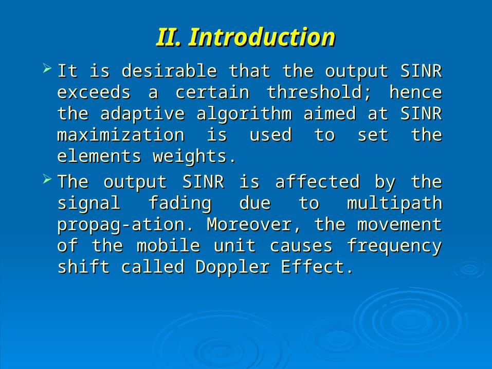
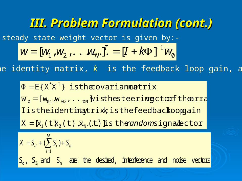
I is the identity matrix, k is the feedback loop gain, and
The steady state weight vector is given by:-
01
21 ][]......,,[ wkIwwww TN
vectorsignaltheis(t)]x(t),....x(t),x[X
gainloopfeedback the isk matrix;identity the isI
arraytheofvectorsteeringtheis],....ww,[ww
matrixcovariancetheis}XE{XΦ
TN21
0N02010
T*
random
1
d I n
( )
S , S and S are the desired, interference and noise vectorsi
M
d i ni
X S S S

III. Problem Formulation (cont.)III. Problem Formulation (cont.)
)sin()(where
]1,,,....,[
max1
0121
i
jji
Tjjj
l
eeew N
Assuming that the desired narrowband signal comes from θmax:
The SINR is calculated from:
M
iIn
d
iPP
PSINR
1
log10
similarisPforexpressionThe
}]Re{2||[
||
iI
1 2
*1
1
2
1
22
elementperpowerreceivedS
ationautocorrelnormalizedtheis
wwwSP
wP
Td
N
n
N
mdmn
N
nnTdd
N
iin
nm

Loo’s model applies to frequency-non-selective Loo’s model applies to frequency-non-selective terrestrial mobile radio channels, where the line-of-terrestrial mobile radio channels, where the line-of-sight sight m(t)m(t) component under-goes slow-amplitude component under-goes slow-amplitude lognormally-distributed fluctuations, caused by lognormally-distributed fluctuations, caused by shadowing effects. shadowing effects. m(t)m(t) is given as: is given as:
where and denote the Doppler frequency where and denote the Doppler frequency and phase of the line-of-sight componentand phase of the line-of-sight component
respectively, and is the lognormal respectively, and is the lognormal process, with and are the mean and process, with and are the mean and variance, of the white Gaussian process .variance, of the white Gaussian process .
(2 )1 2( ) ( ) ( ) ( ). j f tm t m t jm t t e
f
3 3 3( )( ) t mt e
3m 23
IV. Modelling of Mobile Fading IV. Modelling of Mobile Fading ChannelChannel
3( )t

The short-term fading caused by the multipath The short-term fading caused by the multipath propagation, behaves like the Rice process, and it is propagation, behaves like the Rice process, and it is represented by a complex-valued Gaussian random represented by a complex-valued Gaussian random processprocess
2 ( )t
1 2( ) ( ) ( )t t j t
1 1 2( ) ( ) ( )t t t
2 1 2ˆ ˆ( ) ( ) ( )t t t
where,where,
IV. Modelling of Mobile Fading Channel (Cont.)IV. Modelling of Mobile Fading Channel (Cont.)
Here,Here, and represent zero-mean colored and represent zero-mean colored Gaussian random processes, andGaussian random processes, and is the Hilbert is the Hilbert transform of for (transform of for (ii=1, 2). =1, 2).
1( )tˆ ( )i t
( )i t
The Modified Loo’s process is given asThe Modified Loo’s process is given as ( ) | ( ) ( ) |t t m t
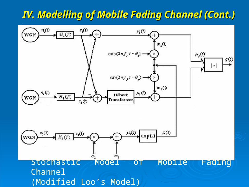
IV. Modelling of Mobile Fading Channel (Cont.)IV. Modelling of Mobile Fading Channel (Cont.)
Stochastic Model of Mobile Fading Channel (Modified Loo’s Model)

The simulation model for modified Loo process approximates the behaviour of The simulation model for modified Loo process approximates the behaviour of the stochastic reference model, where the three stochastic Gaussian random the stochastic reference model, where the three stochastic Gaussian random processes by deterministic Gaussian processes of the formprocesses by deterministic Gaussian processes of the form
Therefore, can be written as:Therefore, can be written as:
IV. Modelling of Mobile Fading Channel (Cont.)IV. Modelling of Mobile Fading Channel (Cont.)
( )( 1, 2,3)i t i
, , ,1
( ) cos(2 ), 1,2,3iN
i i n i n i nn
t c f t i
( )( 1,2,3)i t i 1 1
1 1, 1, 1, 2, 2, 2,1 1
( ) cos(2 ) cos(2 )N N
n n n n n nn n
t c f t c f t
1 2
2 1, 1, 1, 2, 2, 2,1 1
( ) sin(2 ) sin(2 )N N
n n n n n nn n
t c f t c f t
3
3 3 3, 3, 3, 31
( ) cos(2 )N
n n nn
t c f t m

IV. Modelling of Mobile Fading Channel (Cont.)IV. Modelling of Mobile Fading Channel (Cont.)
Simulation Model of Mobile Fading Channel that approximates the stochastic model.

The simulation model for modified Loo process approximates the behaviour of the stochastic The simulation model for modified Loo process approximates the behaviour of the stochastic reference model, where the random processes reference model, where the random processes
are replaced byare replaced by
Therefore, can be written as:Therefore, can be written as:
IV. Modelling of Mobile Fading Channel (Cont.)IV. Modelling of Mobile Fading Channel (Cont.)
( )( 1, 2,3)i t i
, , ,1
( ) cos(2 ), 1,2,3iN
i i n i n i nn
t c f t i
( )( 1,2,3)i t i 1 1
1 1, 1, 1, 2, 2, 2,1 1
( ) cos(2 ) cos(2 )N N
n n n n n nn n
t c f t c f t
1 2
2 1, 1, 1, 2, 2, 2,1 1
( ) sin(2 ) sin(2 )N N
n n n n n nn n
t c f t c f t
3
3 3 3, 3, 3, 31
( ) cos(2 )N
n n nn
t c f t m
,i nc ,i nf The Doppler coefficients and for (The Doppler coefficients and for (ii=1,2,3) can be=1,2,3) can be calculated using Mean Square Error method.calculated using Mean Square Error method.

V. Results & DiscussionV. Results & Discussion Two arrangements of 12 array elements are used:Two arrangements of 12 array elements are used:
• Arrangement (a): The elements are uniformly Arrangement (a): The elements are uniformly spaced by spaced by λλ/2./2.
• Arrangement (b): Non-Uniform array elements Arrangement (b): Non-Uniform array elements arrangement with arrangement with spacings (0.85λ,0.7λ,0.5λ,0.4λ,spacings (0.85λ,0.7λ,0.5λ,0.4λ,
0.25λ, 0.1λ ,0.25λ ,0.4λ ,0.5λ ,0.7λ ,0.85λ) 0.25λ, 0.1λ ,0.25λ ,0.4λ ,0.5λ ,0.7λ ,0.85λ)
In arrangement (b), the elements are arranged such In arrangement (b), the elements are arranged such that the elements in the middle of the array are closer that the elements in the middle of the array are closer to each other than the elements in the edges of the to each other than the elements in the edges of the array.array.
It is shown that non-uniform array (arrangement (b)) It is shown that non-uniform array (arrangement (b)) has better performance than the uniformly spaced has better performance than the uniformly spaced array in terms of sensitivity to pointing errors in non-array in terms of sensitivity to pointing errors in non-fading and fading environments.fading and fading environments.

V. Results & Discussion (Cont.)V. Results & Discussion (Cont.)
Performance of 12-element adaptive array vs. Performance of 12-element adaptive array vs. pointing error (without fading). pointing error (without fading).

V. Results & Discussion (Cont.)V. Results & Discussion (Cont.)
Simulation of the received faded signal for light and Simulation of the received faded signal for light and heavy shadowing regions, respectively.heavy shadowing regions, respectively.

V. Results & Discussion (Cont.)V. Results & Discussion (Cont.)
Output SINR vs. SNR for uniformly and non- Output SINR vs. SNR for uniformly and non- uniformly spaced array.uniformly spaced array.

V. Results & Discussion (Cont.)V. Results & Discussion (Cont.)
Output SINR vs. time for light shadowing regionsOutput SINR vs. time for light shadowing regions, , with and without pointing error (uniform array).with and without pointing error (uniform array).

V. Results & Discussion (Cont.)V. Results & Discussion (Cont.)
Variance and mean of output SINR vs. pointing Variance and mean of output SINR vs. pointing error for uniformly and non-uniformly spaced-array. error for uniformly and non-uniformly spaced-array.
VI. Conclusions VI. Conclusions
A suitable simulation model for mobile fading channel A suitable simulation model for mobile fading channel has been suggested.has been suggested.
A comparison between uniformly and non-uniformly A comparison between uniformly and non-uniformly spaced array has been conducted.spaced array has been conducted.
It is shown that non-uniform array (arrangement (b)) It is shown that non-uniform array (arrangement (b)) has better performance than the uniformly spaced has better performance than the uniformly spaced array in terms of sensitivity to pointing errors in non-array in terms of sensitivity to pointing errors in non-fading and fading environments.fading and fading environments.
It is shown that mean output SINR of the non-uniform It is shown that mean output SINR of the non-uniform array is greater than that of the uniformarray is greater than that of the uniform

Thank youThank you