Embed Size (px)
Citation preview

Performance Limits of Delay Lines Based on "Slow" Light
Robert W. BoydInstitute of Optics and
Department of Physics and AstronomyUniversity of Rochester
Representing the DARPA Slow-Light-in-Fibers Team:Daniel Blumenthal, Alexander Gaeta, Daniel Gauthier, John Howell, and Alan Willner.
Presented Photonics West, January 24, 2005.

Motivation: Maximum Slow-Light Time Delay
Proposed applications: controllable optical delay linesoptical buffers, true time delay for synthetic aperture radar.
Key figure of merit:normalized time delay = total time delay / input pulse duration ≈ information storage capacity of medium
“Slow light”: group velocities < 10-6 c !
Best result to date: delay by 4 pulse lengths (Kasapi et al. 1995)
But data packets used in telecommunications contain ≈ 103 bits
What are the prospects for obtaining slow-light delay lines with 103 bits capacity?

Review of Slow-Light Fundamentals
slow-light medium, ng >> 1
Tg =L
vg=Lngc
ng = n+ ωdn
dω
Tdel = Tg − L/c =L
c(ng − 1)
group velocity:
group index:
group delay:
controllable delay:
vg =c
ng
L
To make controllable delay as large as possible: • make L as large as possible (reduce residual absorption) • maximize the group index


[2] Matsko, Strekalov, and Maleki, Opt. Express 13, 2210, 2005.[1] Boyd, Gauthier, Gaeta, and Willner, Phys. Rev. A 71, 023801, 2005.
Modeling of Slow-Light Systems
Another recent study [2] reaches a more pessimistic (although entirely mathematically consistent) conclusion by stressing the severity of residual absorption, especially in the presence of Doppler broadening.
We conclude that there are no fundamental limitations to the maximum fractional pulse delay [1]. Our model includes gvd and spectral reshaping of pulses.
However, there are serious practical limitations, primarily associated with residual absorption.
Our challenge is to minimize residual absorption.

Our Team:
Photonic Crystal Fiber - Utilize EIT effects in
gas-filled fiber.
Stimulated Scattering - Raman/Brillouin effect
produces gain/delay.
Population Oscillations - Pumped Er-doped fiber
with control beam toprovide gain/delay.
control
signal in signal outcontrollable delay
3 Approaches:
control
Daniel Blumenthal, UC Santa Barbara; Alexander Gaeta, Cornell University; Daniel Gauthier, Duke University; Alan Willner, University of Southern California; Robert Boyd, John Howell, University of Rochester
DARPA/DSO Project on Applications of Slow Light in Optical Fibers

Slow Light and Optical Buffers
All-Optical Switch Use of Optical Buffer for Contention Resolution
inputports
outputportsswitch
But what happens if twodata packets arrive simultaneously?
slow-lightmedium
Controllable slow light for optical buffering can dramatically increasesystem performance.

Challenge/GoalSlow light in a room-temperature solid-state material.
Our approaches:1. Stimulated Brillouin Scattering2. Stimulated Raman Scattering3. Wavelength Conversion and Dispersion4. Coherent Population Oscillations a. Ruby and alexandrite b. Semiconductor quantum dots (PbS) c. Semiconductor optical amplifier d. Erbium-doped fiber amplifier
Also: application of slow-light to low-light-level switching

DiodeLaser Fiber Amplifier
50/50
SBS Generator
Modulator
PulseGenerator
SBS Amplifier
Isolator
Oscilloscope
DetectorCirculator
CirculatorPolarization
Control
RF AmplifierVariable
Attenuator
Slow-Light via Stimulated Brillouin Scattering • Rapid spectral variation of the refractive response associated with SBS gain leads to slow light propagation• Supports bandwidth of 100 MHz, large group delays• Even faster modulation for SRS
in out
typical data
Okawachi, Bigelow, Sharping, Zhu, Schweinsberg, Gauthier, Boyd, and Gaeta Phys. Rev. Lett. 94, 153902 (2005). Related results reported by Song, González Herráez and Thévenaz, Optics Express 13, 83 (2005).

Increasing the Bandwidth of aSlow Light Medium
| ( )| [ ( )]
arg ( ) ( ) [ ( )]
t A d
t dA= +
= +
1
10 0
Frequency-dependent gainflattened near center ofresonances
Can cancel lowest-ordercontribution to pulse distortion
Generalized distortion definition
Approach: Use two nearby Brillouin gain lines to flatten the response

Demonstration of CompensatedSlow Light
Constraints: maximum distortion < 0.05, peak gain of a single gain line: g0L<5
dth
(
Theoretical and Experimental Results
Maximum relative pulse delay of 0.53 ata distortion of 0.05.
9-fold improvement in relative pulsedelay using two gain lines rather than onefor a given distortion criterion.
Delay accuracy at maximum delay: +/-2% (corrected for detection system noise)
Delay-Bandwidth Product of 0.23 at adistortion of 0.05
9-fold increase in Delay-Bandwidthproduct
Bit rate at maximum delay: ~28 Mbits/s(assuming time slot is twice the FWHMpulse width)
0 1 1.60
1
rela
tive
dela
y t
Δ d b
bandwidth Δ b/ γ
Comparison of compensated and uncompensated delay
singlet
doublet

-29
-27
-25
-23
-21
-19
-17
-15
9.76 9.78 9.8 9.82 9.84 9.86 9.88 9.9 9.92
Without Phase Mod.
With 10M Clock Phase Mod.
Study of SBS Gain Spectrum Broadening
Frequency spacing between pump and signal (GHz)
Gai
n (
dB
)
1
3
5
7
9
11
13
15
• Gain BW: 28 MHz 60 MHz
Expand the BW by phase modulating the pump
10 MHz clock phase modulating the pump
BW = 60 MHz
BW= 28 MHz

Slow-Light by Stimulated Raman Scattering
• The Raman linewidth (~3 THz) is much greater than that of Brillouin.
• Co- or counter-propagating configurations can be used.
• Spectral interferometry between test and reference pulses is used(10 fs delay resolution at low peak power) to measure delays.
Alex Gaeta, Cornell

SRS Delay Results
• Observed delay is linear vs. gain• Optimized delay:
⇒ 370 fs delay w/ 430 fs input.⇒ 85% of pulse width⇒ Raman linewidth of 3 THz
- sufficient for telecom
J. E. Sharping, Y. Okawachi, and A. L. Gaeta, “Wide bandwidth slow light using a Ramanfiber amplifier,” Opt. Express 13, 6092 (2005). 4

Slow Light via Coherent Population Oscillations
1/T1
PRL 90,113903(2003); Science, 301, 200 (2003)
• Ground state population oscillates at beat frequency δ (for δ < 1/T1).
Γba
=1T
12γ
ba=
2T
2
a
bsaturablemedium
ω
ω + δ ω + δ
E1,
E3,
measure absorption
• Population oscillations lead to decreased probe absorption (by explicit calculation), even though broadening is homogeneous.
• Rapid spectral variation of refractive index associated with spectral hole leads to large group index.
• Ultra-slow light (ng > 106) observed in ruby and ultra-fast light (ng = –4 x 10⁵) observed in alexandrite by this process.
• Slow and fast light effects occur at room temperature!
absorptionprofile

PRL 90,113903 (2003)
Matt Bigelow and Nick Lepeshkin Studying Slow Light in Ruby
Demonstration of slow light in a room temperature solid.

Prospects for Large Fractional Delays Using CPO
collection oftwo-level atomsω
ω + δ
ω
ω + δ
80 40 0 40 800
0.2
0.8
1
δ T1
prob
e ab
sorp
tion
ΩT1 = 2 ∆ = 0 T1/T2 = 100
0.6
0.4
ΩT1 = 5
ΩT1 = 10
ΩT1 = 20 ΩT1 = 40
Boyd et al., Laser Physics 2005.
Absorption
0
0.04
0.08
0.12
grou
p in
dex
/ω T
1
-15 0 15δ T1
∆ = 0
ΩT1 = 2
ΩT1 = 10
ΩT1 = 5
ΩT1 = 40
ΩT1 = 20
T1/T2 = 100
Group index
0 50 1000
10
40
20
30
max
imum
del
ay in
pul
se w
idth
s
∆ = 0
T1/T2 = 100
Rabi frequency times T1
Maximum fractional delay
Strong pumping leads to high transparency,large bandwidth, and increased fractionaldelay.

Slow Light in SC Quantum Dot Structures
3 ps
PbS Quantum Dots (2.9 nm diameter) in liquid solution
Excite with 16 ps pulses at 795 nm; observe 3 ps delay
30 ps response time (literature value)

Pulse Propagation in a Semiconductor Optical Amplifier
Dan Blumenthal, UCSD

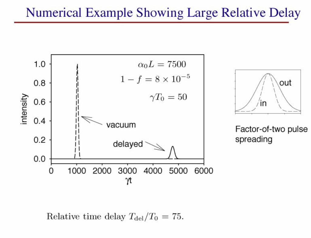
FWM-Dispersion Delay Scheme - Principle of Operation
• T =2 D( ) ( s – p)
• Pulsed pump ~500 ps
dispersive delay D(λ)
FWM wavelength conversion
FWM wavelength conversion
ΔT
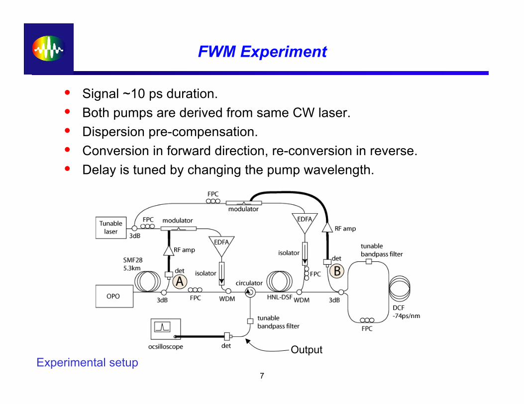
FWM Experiment
• Signal ~10 ps duration.• Both pumps are derived from same CW laser.• Dispersion pre-compensation.• Conversion in forward direction, re-conversion in reverse.• Delay is tuned by changing the pump wavelength.
Experimental setupOutput
7

FWM-Dispersion Delay Results
• Results:⇒ 800 ps of delay⇒ Pulse quality is preserved⇒ No wavelength shift⇒ Phase information is preserved⇒ 10 Gb/s simulation implies a 3-dB
received power penalty
Measured, delayed pulses
Results of 10 Gb/s simulation (w/ Willner group)
J. E. Sharping, Y. Okawachi, J. van Howe, C. Xu, Y. Wang, A. E. Willner, and A. L. Gaeta, “All-optical wavelength andbandwidth-preserving pulse delay based on parametric wavelength conversion and dispersion,” submitted to Opt. Express(2005). 8

Summary
Slow-light techniques hold great promise for applications in telecom and quantum information processing
Good progress being made in devloping new slow-light techniquesand applications
Different methods under development possess complementary regimes of usefullness

Thank you for your attention.
And thanks to NSF and DARPA for financial support!

Thank you for your attention!