Embed Size (px)
Citation preview

Smart Grid and Renewable Energy, 2012, 3, 239-245 http://dx.doi.org/10.4236/sgre.2012.33033 Published Online August 2012 (http://www.SciRP.org/journal/sgre)
239
Performance Investigation of a Simple Reaction Water Turbine for Power Generation from Low Head Micro Hydro Resources
Abhijit Date, Ashwin Date, Aliakbar Akbarzadeh
School of Aerospace, Mechanical and Manufacturing Engineering, RMIT University, Melbourne, Australia. Email: [email protected] Received January 30th, 2012; revised May 3rd, 2012; accepted May 10th, 2012
ABSTRACT
Theoretical investigation has shown a simple reaction water turbine would perform better when it spins faster. And for the simple reaction turbine water turbine to spin faster under constant water head, its diameter should be smaller. This paper reports on a performance analysis based on the experimental data collected from different performance tests car-ried on two simple reaction water turbine prototypes. Two new designs of simple reaction water turbines and their manufacturing methods are reported. The two turbines under investigation have different rotor diameters Φ 0.243 m and Φ 0.122 m. In case of the simple reaction water turbine the water enters into the turbine axially and exits tangentially through nozzles located on the outer periphery of the turbine. Further this paper will discuss the performance character-istics of stationary turbine i.e. zero power produced and performance characteristics of turbine producing power. It was found that rotor diameter affects the maximum rotational speed of the simple reaction turbine for constant supply head. It was also found that faster the turbine spins its performance improves. The two turbines were tested between supply head range of 1 m to 4 m. Keywords: Barker’s Mill; Hydro Electric Low Head; Simple Reaction Turbine; Water Turbine
1. Introduction
The role of renewable energy in tomorrow’s world is of great significance for the global environmental stability. Sun, wind and flowing or stored hydro (water) are con- sidered the most common renewable energy sources for power generation. Out of these three renewable energy resources, the advantage of hydro energy is that it can continuously supply energy and can serve as a base power. The annual global hydropower production is very small as compared to the global power consumption. However the technically exploitable hydro power poten- tial available throughout the world is far more than is actually been used as illustrated by the data from Sterngerg Kaygusz and Taylor [1-3]. The world hydro power scenario show that the technically exploitable po-tential of hydro energy is about 14,000 TWh year and the economically exploitable potential is about 8000 TWh year, where as the present global hydro power generation stands at 2800 TWh/year [2,4].
Looking at the above estimates it is clear that there is a large potential of hydropower waiting to be exploited. Further there is a large gap between technically exploit- able and economically exploitable potential [5,6] which
creates a need for further research in hydropower tech- nology to make it more economic and help to reduce this gap. To date most of the large hydropower sites have been exploited [7,8]. However, most of the small and micro hydro sites are yet to be exploited.
Thus keeping in mind that the world currently is still heavily dependent on non-renewable energy sources (fossil fuels) such as coal, oil and natural gases, which are rapidly diminishing and becoming increasingly more expensive, the role of renewable energy has been recog- nized to be significantly important in sustainable future development. Hydropower is a good example of renew- able energy; its present use and potential application to future power generation cannot be underestimated.
The finding reported in this paper is based on the theoretical and experimental investigations previously reported by Date and Akbarzadeh [9,10]. Initially in this paper theoretical performance analysis of a simple reac- tion water turbine has been presented followed by the design and fabrication method for split reaction water turbine. Later the experimental set-up is discussed along with the experimental procedures used. Further the ex- perimental results are discussed with uncertainty analysis presented for the experimental performance estimation.
Copyright © 2012 SciRes. SGRE

Performance Investigation of a Simple Reaction Water Turbine for Power Generation from Low Head Micro Hydro Resources
240
parameters as a function of *T.
2. Theoretical Analysis of Simple Reaction Water Turbine
Following the work done by Akbarzadeh [11] on para- metric analysis of simple reaction water turbine, effi- ciency and angular speed have been drawn as a function of torque and shown in Figure 1. The universal charac- teristics of this turbine are presented graphically in using the dimensionless torque * as the independent vari- able. Reducing the load torque applied to turbine from the stationary to runaway condition corresponds to mov- ing from right to left on the horizontal axis. Figure 1 shows the graphical representation of parameters
T
* and * as a function of non-dimensional torque . *T
The nature of an ideal simple reaction turbine as shown in Figure 1 is illuminating, which shows how the efficiency increases with increase in angular speed. Figure 1 further shows how a simple reactions turbine pumps more water through the turbine as the angular speeds increases due to centrifugal pumping effect. This cen- trifugal pumping effect significantly increases the power production capacity of this turbine and presents an op- portunity to develop a compact water turbine for low head hydro-power applications with low specific energy.
3. Simple Reaction Turbine and Specific Speed
Specific speeds are commonly used as a tool for com- parison of the characteristics of similar hydraulic ma- chines. Here this tool is applied to simple reaction water turbine, by using the formulation provided by Turton [12] for the specific speed of turbines, the following relation between specific speed and efficiency of a simple reac- tion turbine has been derived as discussed by Akbar- zadeh [11].
–3 4
3 4
22
1s
AK
R
(1)
Figure 1. Graphical presentationof dimensionles.
The effect of geometry on the relation between specific speed and efficiency is expressed in terms of A R . However this can be changed to ratio of diameters i.e. D d where 2D R and d is the diameter of the noz- zle. Defining an equivalent exit nozzle diameter de as,
2ed
A (2)
Using the relation for the equivalent exit nozzle di- ameter from Equation (2), we can re-write Equation (1) as follows,
–3 4
3 4
22
1e
s
dK
D
(3)
It is not possible to present as a function of sK in an explicit form [11]. However, the variation of as a function of sK is presented for several values of diame-ter ratio. It is seen in from Figure 2 that a simple reaction turbine achieves higher efficiency for machines of higher diameter ratio eD d , i.e. for a given diameter D, a smaller nozzle exit area will improve efficiency. Since we relate capacity of the turbine to the nozzle exit area, we can then say that for the same specific speed and rotor diameter, machines of smaller capacities would be more efficient. It can be also seen from Figure 2 that efficiency of a simple reaction turbine improves as the specific speed
sK increases. Considering the definition of sK in Equa-tion (3) this is equivalent to saying higher efficiencies are achieved at high rotational speeds and higher flow rates. This can be considered as an important conclusion in rela-tion to the characteristics of simple reaction water turbine.
4. Design of Simple Reaction Water Turbine
This new design has very simple geometry, it can be manufactured using a very basic skill set and can be made from locally available materials (so low cost). The
Figure 2. Variation of efficiency with specific speed for various diameter ratios.
Copyright © 2012 SciRes. SGRE

Performance Investigation of a Simple Reaction Water Turbine for Power Generation from Low Head Micro Hydro Resources
241
split reaction turbine can produce power from very low head hydro-sites (head range ≥0.3 m and flow rate of ≥10 litres per second). This simple reaction turbine is named as “Split Reaction Turbine (SRT)” after its me- thod of manufacturing [13,14]. Figure 3 shows the first SRT1 that has a diameter of 243 mm and height of 120 mm with two exit nozzles each 6 mm wide. Therefore the total exit area is 1440 mm². Figure 3 shows the second SRT2 that has a diameter of 122 mm and height of 120 mm with two exit nozzles. The exit nozzle width of the SRT2 could be varied in three steps 4.2 mm, 5.4 mm and 8 mm. Therefore the total exit area is 1440 mm². The exit nozzle profile and the inner wall profile of the turbine plays very important role in the efficiency of the turbine and can be analyzed following the boundary layer and viscous flow theory [15-20].
5. Experimental Test Rig and Test Procedure
Figure 4 shows the picture of the water turbine test rig used for the performance analysis of the simple reaction turbine prototypes. This test rig is divided into two main sections: 1) Hydraulic power input unit, which is com- prised of water pump, flow meter, pressure gauge, deliv- ery pipe, and flow control system; 2) Power output unit comprised the simple reaction water turbine with the inlet rotary seal arrangement, the electric generator, the DC electronic load, the tachometer.
Figure 3. Pictures of two split reaction water turbines.
DC generator
Electronic DC load
Tachometer Supply pressure gauge
Flow meter
Flow control device
Water pump
Figure 4. Water turbine test rig.
Here the water stored in the water tank (tank capacity 0.5 m³) is pressurized with the water pump and then this pres- surized water is supplied to the turbine. After the water tur- bine extracts the mechanical power from the water, it is discharged back into the water tank for re-circulation through the systems. The mechanical power produced by the turbine is transmitted to the electric generator through the solid flange coupling. Then the electric power pro- duced by the generator is dumped into the DC electronic load. The voltage and current are measured this helps to estimate the electrical power output.
The stationary test is carried under different hydro- static supply heads. This technique helps to estimate the stationary torque produced by the turbine. The stationary torque is equivalent to the maximum torque that turbine can produce at a certain hydrostatic supply head. It also helps to estimate the stationary water flow rate through the turbine. This is equivalent to the minimum water flow rate that a constant hydrostatic supply head can produce. Finally, this test technique helps to estimate the stationary discharge coefficient of the turbine.
Both the turbine prototypes discussed in Section 4 have been tested with this technique. Figure 5 shows the experimental set-up used in the stationary test. During the stationary test, torque arm is connected to the turbine shaft and the force sensor (Dana Load cell capacity 20 kgf), the force sensor measures the tangential force at the torque arm and this is used to estimate the stationary torque. The force sensor is secured rigidly to the test rig frame as shown in Figure 5. From this measurement, the torque is deduced and hence the total reaction force of the exiting water jets. Here water is supplied at constant hydrostatic head, the supply pressure/head is monitored on the pressure gauge, the flow rate is monitored on the flow meter and the force (proportional to torque) is monitored on the force sensor indicator (strain indicator), at the same time all these parameters are also recorded. In the stationary test, the flow rate is only dependent on
Load Cell (Force sensor)
Torque arm Pressure
Flow
Strain Indicator
Figure 5. Stationary torque and flow rate measurement set-up.
Copyright © 2012 SciRes. SGRE

Performance Investigation of a Simple Reaction Water Turbine for Power Generation from Low Head Micro Hydro Resources
242
the supplied hydrostatic head as there is no centrifugal pumping effect present that could alter the flow rate.
The relative velocity of the water jet at both the exit nozzles is equal to the total volume flow rate of water supplied to the turbine divided by the total exit nozzle area. Ideally the torque produced at the turbine shaft should be equal to the estimated torque, here estimated torque is equal to product of absolute velocity, total mass flow rate and mean turbine radius (when the turbine is stationary the absolute velocity is equal to the relative velocity). The turbine shaft torque is equal to the product of the measured force (value of force in Newton) at the turbine shaft times the torque arm length (in meters). The stationary test results for both the turbine prototypes are analyzed and discussed in next section.
Power test is used to measure and estimate the overall performance of the turbine prototypes. During this test the hydrostatic supply head is kept constant while the load on the turbine is varied. This technique helps to es- timate the maximum power produced by a turbine for a constant hydrostatic head and the maximum energy con-version efficiency (overall efficiency) of the hydroelec-tric unit. It also helps to estimate the water flow rate while turbine is rotating. Here the flow rate increases with the increase in rotational speed due to centrifugal pumping effect as discussed in Section 2 and illustrated by Figure 1. Further, this test technique helps to carry out the overall energy balance analysis of the hydroelec-tric unit.
Both the prototypes were tested with power test tech-nique at different hydrostatic supply pressures/heads (range 1 m to 4 m) to estimate their performance charac-teristics. At the beginning of a power test, the turbine is allowed to rotate free without any electric load or some times with very small electrical load, while the supply pressure is held constant. At the same time parameters like flow rate, rotational speed, output voltage, and out-put current are recorded. Then the electric load is gradu-ally increased in steps, this tends to decrease the rota-tional speed of the turbine. This decrease in rotational speed reduces the centrifugal pumping effect causing the supply pressure to increase slightly. The supply pressure is then adjusted to its original value with the flow control device (3 phase frequency controller) connected to the water pump as shown in Figure 4. The parameters like supply pressure, flow rate, rotational speed, output volt-age and output current are recorded for each step when load is increased. The increase in load is continued till the turbine slows down to about quarter of no-load rota-tional speed. This procedure is repeated for different supply pressures to analysis the performance characteris-tics of both turbine prototypes.
The mechanical power produced by the turbine is
equal to sum of electrical power output, plus the power lost in DC generator, plus the power lost in overcoming turbine air drag plus the power lost in friction at the ro- tary seal. For a permanent magnet DC motor/generator only a few constants and equations linking them are needed to describe the relationship between speed, torque and current [21]. The DC motor torque constant tK is defined as the ratio between the torque and the current. The DC motor/generator constant tK is estimated by using the equations and the performance data provided in the Baldor DC motor catalogue and the numerical value of tK is estimated as 0.902.
The electrical power output from the DC motor/gen- erator EW (Watts) can be estimated using following equation,
E t g gW K I V I g (4)
Here gI is the generator output current (Amp) and
gV is the generator output voltage (Volts) ad both are measured during the power test. Finally the turbine out-put power (i.e. the actual mechanical power output from turbine before any bearing frictional loss, mechanical seal frictional loss and turbine drag loss) (Watts) is estimated using following equation,
TW
lossT EW W W (5)
The power loss loss in overcoming the turbine air drag plus the power loss in friction at the rotary seal was measured using the procedure discussed in the earlier publications [10,13]. The turbine efficiency is the ratio of the actual mechanical output power divided by the rate at which potential energy is supplied to the turbine.
W
TW
mgH
(6)
6. Experimental Results and Discussion
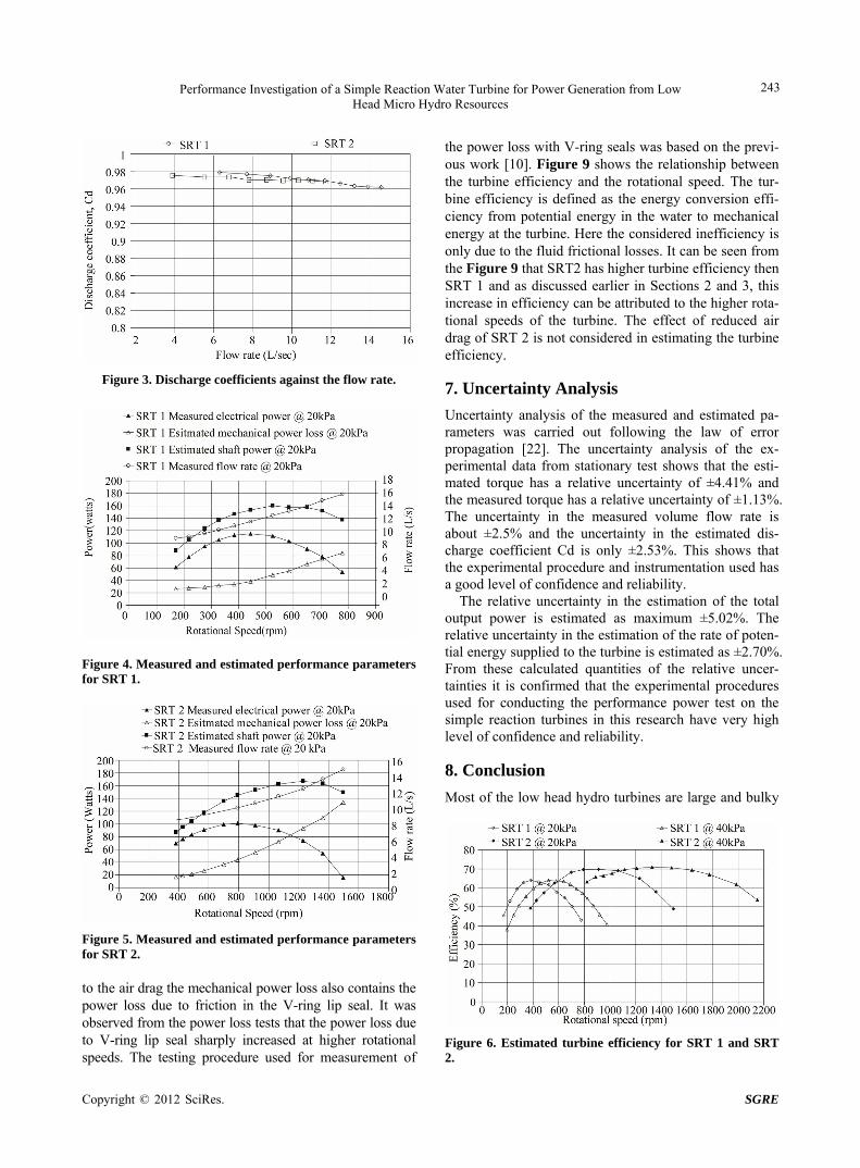
Stationary tests have shown that the discharge coefficient for both SRT prototypes is quite similar and it varies between a numerical value of 0.96 to 0.98. Figure 6 shows the variation of discharge coefficient for SRT 1 and SRT 2 with respect to flow rate of water flowing through the turbine. This shows that both turbine proto- types have similar fluid frictional losses when the turbine is held stationary.
Figures 7 and 8 show the relationship between y-axis. Overall it can be seen that for both the turbines the fric-tional power loss increases as the rotational speed. 800 rpm as can be seen from Figure 8. From experiments it was observed that the air drag increases as the turbine exit nozzle width of increase, this was due to shape of turbine drifting away from a perfect circle to more ellip-tical as the exit nozzle width is increased. In addition
Copyright © 2012 SciRes. SGRE
Performance Investigation of a Simple Reaction Water Turbine for Power Generation from Low Head Micro Hydro Resources
243
Figure 3. Discharge coefficients against the flow rate.
Figure 4. Measured and estimated performance parameters for SRT 1.
Figure 5. Measured and estimated performance parameters for SRT 2. to the air drag the mechanical power loss also contains the power loss due to friction in the V-ring lip seal. It was observed from the power loss tests that the power loss due to V-ring lip seal sharply increased at higher rotational speeds. The testing procedure used for measurement of
the power loss with V-ring seals was based on the previ-ous work [10]. Figure 9 shows the relationship between the turbine efficiency and the rotational speed. The tur-bine efficiency is defined as the energy conversion effi-ciency from potential energy in the water to mechanical energy at the turbine. Here the considered inefficiency is only due to the fluid frictional losses. It can be seen from the Figure 9 that SRT2 has higher turbine efficiency then SRT 1 and as discussed earlier in Sections 2 and 3, this increase in efficiency can be attributed to the higher rota-tional speeds of the turbine. The effect of reduced air drag of SRT 2 is not considered in estimating the turbine efficiency.
7. Uncertainty Analysis
Uncertainty analysis of the measured and estimated pa- rameters was carried out following the law of error propagation [22]. The uncertainty analysis of the ex-perimental data from stationary test shows that the esti-mated torque has a relative uncertainty of ±4.41% and the measured torque has a relative uncertainty of ±1.13%. The uncertainty in the measured volume flow rate is about ±2.5% and the uncertainty in the estimated dis- charge coefficient Cd is only ±2.53%. This shows that the experimental procedure and instrumentation used has a good level of confidence and reliability.
The relative uncertainty in the estimation of the total output power is estimated as maximum ±5.02%. The relative uncertainty in the estimation of the rate of poten- tial energy supplied to the turbine is estimated as ±2.70%. From these calculated quantities of the relative uncer- tainties it is confirmed that the experimental procedures used for conducting the performance power test on the simple reaction turbines in this research have very high level of confidence and reliability.
8. Conclusion
Most of the low head hydro turbines are large and bulky
Figure 6. Estimated turbine efficiency for SRT 1 and SRT 2.
Copyright © 2012 SciRes. SGRE
Performance Investigation of a Simple Reaction Water Turbine for Power Generation from Low Head Micro Hydro Resources
244
as they have to handle large volume flow rates to pro- duce reasonable power and then have low efficiency. The above analysis shows that the simple reaction water with small diameter can efficiently produce power without having to be large and bulky. The energy conversion efficiency of a simple reaction water turbine increases with the increase in the rotational speed. The theoretical analysis also shows that the turbine efficiency approaches its maximum value as the load torque approaches the 50% of the stationary torque. Theoretical analysis also shows that a simple reaction water turbine will spin faster as the turbine diameter is reduced. From the experimental analysis it was confirmed that a turbine with smaller di- ameter tends to rotate faster in comparison with a turbine with larger diameter, when both are supplied with same hydro static head. Additionally the small diameter rotor will have less air drag power losses. The theoretical pre- dictions have shown that a simple reaction water turbine would have higher efficiency at higher rotational speeds. SRT 2 (Φ 0.122 m) has approximately half the diameter as compared to SRT 1 (Φ 0.243 m) and the test results have shown that SRT 2 rotates twice as fast as SRT1 under same hydro static head. Further the test results have shown that SRT 2 has higher turbine efficiency as compared with SRT 1. So it can be concluded that the higher turbine efficiency is due to the fact that turbine rotates at higher rotational speeds and is supported by the theoretical predictions. The uncertainty analysis has shown that the experimentally measured results and the estimated results have reasonable relative uncertainties and so the findings of this study can be used as a basis for future investigation. Future work should involve ex- perimental investigation of SRT’s with even smaller di-ameters and smoother nozzle profiles.
REFERENCES [1] G. W. Chang, H.-W. Lin and S.-K. Chen, “Modeling
Characteristics of Harmonic Currents Generated by High- Speed Railway Traction Drive Converters,” IEEE Trans- actions on Power Delivery, Vol. 19, No. 2, 2004, pp. 766-773. doi:10.1109/TPWRD.2003.822950
[2] R. Taylor, “Hydropower,” In: A. C. J Trinnaman, Ed., Survey of Energy Resources, Elsevier Science, Oxford, 2004, pp. 199-232. doi:10.1016/B978-008044410-9/50012-7
[3] K. Kaygusuz, “Hydropower and the Worlds Energy Future,” Energy Sources, Vol. 26, No. 3, 2004, pp. 215- 224. doi:10.1080/00908310490256572
[4] G. L. Sommers, “Appendix 4: Selected Energy-Related Tables,” In: C. J. Cleveland, Ed., Encyclopedia of Energy, Elsevier, New York, 2004, pp. 721-775.
[5] S. Khennas and A. Barnett, “Micro-Hydro Power: An Option for Socio-Economic Development,” Proceedings
of 6th World Renewable Energy Congress, Brighton, 1-7 July 2000, pp. 1511-1517. doi:10.1016/B978-008043865-8/50313-5
[6] M. J. Khan, M. T. Iqbal and J. E. Quaicoe, “River Current Energy Conversion Systems: Progress, Prospects and Challenges,” Renewable and Sustainable Energy Reviews, Vol. 12, No. 8, 2008, pp. 2177-2193. doi:10.1016/j.rser.2007.04.016
[7] A. Bartle, “Hydropower Potential and Development Acti- vities,” Energy Policy, Vol. 30, No. 14, 2002, pp. 1231- 1239. doi:10.1016/S0301-4215(02)00084-8
[8] E. J. Jeffs, “The Application Potential of Hydro Power,” Energy, Vol. 4, No. 5, 1979, pp. 841-849. doi:10.1016/0360-5442(79)90016-1
[9] A. Date and A. Akbarzadeh, “Design and Cost Analysis of Low Head Simple Reaction Hydro Turbine for Remote Area Power Supply,” Renewable Energy, Vol. 34, No. 2, 2009, pp. 409-415. doi:10.1016/j.renene.2008.05.012
[10] A. Date and A. Akbarzadeh, “Design and Analysis of a Split Reaction Water Turbine,” Renewable Energy, Vol. 35, No. 9, 2010, pp. 1947-1955. doi:10.1016/j.renene.2010.01.023
[11] A. Akbarzadeh, C. Dixon and P. Johnson, “Parametric Analysis of a Simple Reaction Water Turbine and Its Application for Power Production from Low Head Re- servoirs,” Proceedings of Fluids Engineering Division Summer Meeting, New Orleans, 29 May-1 June 2001.
[12] R. K. Turton, “Principles of Turbomachinery,” Chapman & Hall, London, 1995.
[13] A. Date, “Low Head Simple Reaction Water Turbine,” Ph.D. Dissertation, RMIT University, Melbourne, 2009.
[14] A. Date and A. Akbarzadeh, “Design and Cost Analysis of Low Head Simple Reaction Hydro Turbine for Remote Area Power Supply,” International Conference on Re- newable Energy for Sustainable Development in the Asia Pacific Region, Perth, 4 February 2007, pp. 17-25.
[15] H. M. Badr, M. Coutanceau, C. Ménard and S. C. R. Dennis, “Unsteady Flow Past a Rotating Circular Cylinder at Reynolds Numbers 1000 and 10,000,” Journal of Fluid Mechanics, Vol. 220, 1990, pp. 459-484. doi:10.1017/S0022112090003342
[16] M. B. Glauert, “A Boundary Layer Theorem, with Appli- cations to Rotating Cylinders,” Journal of Fluid Mecha- nics, Vol. 2, No. 1, 1957, pp. 89-99. doi:10.1017/S0022112057000762
[17] B. S. Stratford, “The Prediction of Separation of the Tur- bulent Boundary Layer,” Journal of Fluid Mechanics, Vol. 5, No. 1, 1959, pp. 1-16. doi:10.1017/S0022112059000015
[18] R. B. Payne, “Calculations of Unsteady Viscous Flow Past a Circular Cylinder,” Journal of Fluid Mechanics, Vol. 4, No. 1, 1956, pp. 81-86.
[19] G. K. Batchelor, “On Steady Laminar Flow with Closed Streamlines at Large Reynolds Number,” Journal of Fluid Mechanics, Vol. 1, No. 2, 1956, pp. 177-190. doi:10.1017/S0022112056000123
[20] M. B. Glauert, “A Boundary Layer Theorem, with Appli-
Copyright © 2012 SciRes. SGRE

Performance Investigation of a Simple Reaction Water Turbine for Power Generation from Low Head Micro Hydro Resources
Copyright © 2012 SciRes. SGRE
245
cations to Rotating Cylinders,” Journal of Fluid Mecha- nics, Vol. 2, No. 1, 1956, pp. 89-99.
[21] M. Enfield, “Banki-Crossflow Systems Design Guide,” 2005.
http://herehydro.weebly.com/uploads/9/3/9/1/93913/crossflow_design.pdf
[22] M. Drosg, “Dealing with Uncertainties: A Guide to Error Analysis,” Springer-Verlag Press, Berlin, 2007.
Nomenclature R Radius of the turbine (m) T Torque (N-m)
A Total exit area (m2) TW Actual mechanical output power (W)
dC Discharge coefficient Angular speed of the rotor (radian/s) d Exit nozzle diameter (m) Density of water (kg/m3)
edD
Equivalent exit nozzle diameter (m) Turbine Efficiency Turbine diameter (m) SRT Split reaction turbine g Acceleration due to gravity (m/s2) SRT 1 Rotor diameter Φ 243mm H Supply head (m) SRT 2 Rotor Diameter Φ 122mm
SK Specific speed of turbine m Mass flow rate of water through the turbine
(kg/s)