Embed Size (px)
Citation preview

OAKFUDGE ORNL/TM-2001/137
NATIONALLABOMTORY MANAGED BY UT-BATTELLE
FOR THE DEPARTMENT OF ENERGY
Evaluation of !&cm Centrifugal Contactor Hydraulic and Mass Transfer Performance for Caustic-Side Solvent Extraction of Cesium
August2001' Prepared by Joseph F. Birdtiell, Jr., and Kimberly K. Anderson
UT-BATTELLE ORNL-27 (4.00)
DOCUMENT AVAILABILITY
Reports produced after January 1, 1996 are generally available free via the U.S. Department of Energy (DOE) information Bridge.
Web site http://www.osti.gov/bridge
Reports produced before January 1,1996 may be purchased by members of the public from the following source.
National Technical Information Service 5285 Port Royal Road Springfield, VA 22464 Telephone 703-605-6000 (I-800-553-6847) TDD 703-487-4639 Fax 703-605-6900 E-mail [email protected] Web site http://www,ntis.gov/support/ordernowabout.htm
Reports are available to DOE employees, DOE contractors, Energy Technology Data Exchange (ETDE) representatives, and international Nuclear Information System (INIS) representatives from the following source.
Office of Scientific and Technical Information P.O. Box 62 Oak Ridge, TN 37831 Telephone 865-576-8401 Fax 865-576-5728 E-mail [email protected] Web site http://www.osti.gov/contact.html
This report was prepared as an account of work sponsored by an agency of the United States Government. Neither the United States Government nor any agency thereof, nor any of their employees, makes any warranty, express or implied, or assumes any legal liability or responsibility for the accuracy, completeness, or usefulness of any information, apparatus, product, or process disclosed, or represents that its use would not infringe privately owned rights. Reference herein to any specific commercial product, process, or service by trade name trademark, manufacturer, or endorsement recommendation, or favoring by the United States Government or any agency thereof. The views and opinions of authors expressed herein do not necessarily state or reflect those of the United States Government of any agency thereof.

ORNJTM-2001/137
Chemical Technology Division
Evaluation of 5-cm Centrifugal Contactor Hydraulic and Mass Transfer Performance for Caustic-Side
Solvent Extraction of Cesium
Joseph F. Birdwell, Jr.* Kimberly K. Anderson
t Robotics and Process System Division
I Date Published: August 2001
Prepared for the DOE Offrce of Environmental Management
and the Tanks Focus Area Salt Processing Prqject DOE Offrce of Science and Technology,
Prepared by OAK RIDGE NATIONAL LABORATORY
Oak Ridge, Tennessee 3783 1-6285 managed by
UT-BATTELLE, LLC for the
U.S. DEPARTMENT OF ENERGY under contract DE-AC05-OOOR22725.
c

ii

CONTEN?! .
LIST OF TABLES . . . . . . . . . . . . . . . . . . . . . . . . . . . , . . . . . . . . . . . . . . . . . . . ..__. . . . . .._. . . . . . . . . . , . . . . . . . ..,..................................... V
LIST OF FIGURES ................................................................................................................... vii
ABSTRACT ............................................................................................................................... ix
1. INTRODUCTION . . . . . . . . . . . . . . . . . . . . . . . . . . . . . . . . . . . . . . . . . . . . . . . . . . . . . . . . . . . . . . . . . . . . . . . . . . . . . . . . . . . . . . . . . . . . . . . . . . . . . . . . . . . . . . . . . . 1
2. EXPERIMENTAL PROGRAM . . . . . . . . . . . . . . . . . . . . . . . . . . . . . . . . . . . . . . . . . . . . . . . . . . . . . . . . . . . . . . . . . . . . . . . . . . . . . . . . . . . . . . . . . . . . . 3
2.1 EQUIPMENT ................................................................................................................ 6
2.1.1 Centrifugal Contactor ...... . ..................................................................................... 6
2.1.2 Pumps .................................................................................................................. 10
2.1.3 Vessels and Tubing ............................................................................................... 10
2.1.4 Thermometers . . . . . . . . . . . . . . . . . . . . . . . . . . . . . . . . . . . . . . . . . . . . . . . . . . . . . . . . . . . . . . . . . . . . . . . . . . . . . . . . . . . . . . . . . . . . . . . . . . . . . . 10
2.2 CHEMICALS ..,..,,..............,..._.,.......,...............................,...,...................................... 10
2.3 EXPERIMENTAL PROCEDURES . . . . . . . . . . . . . . . . . . . . .,... . . . . . . . . . . . . . . . . . . . . . . . . . . . . . . . . . . . . . . . . . . . . . . . . . . . . . 11
2.3.1 Determination of Dispersion Number.. .................................................................. 1 I
2.3.2 Evaluations of Contactor Hydraulics ..................................................................... 12
2.3.3 Mass Transfer Evaluations .................................................................................... 13
3. RESULTS . . . . . . . . . . . . . . . . . . . . . . . . . . . . . . . . . . . . . . . . . . . . . . . ..t................................................................. I... ,. . . . 14 ‘<
/ 3.1 DISPERSION NUMBER .............................................................................................. 14
3.2 HYDRAULIC PEFORMANCE .................................................................................... 15
3.2.1 Extraction-Condition Throughput Performance .................................................... .15
3.2.2 Stripping-Condition Throughput Performance ....................................................... 19
3.2.3 Summary of Throughput Determination and Hydraulic Performance Results ...... ..2 0
3.3 MASS TRANSFER PERFORMANCE . . . . . . . . . . . . . . . . . . . . . . . . . . . . . . . . . . . . . . . . . . . . . . . . . . .._.................... 22
3.3.1 Extraction-Mode Testing ...................................................................................... 22
3.3.2 Stripping-Mode Testing ............................. . ......................................................... .23
3.4 ADDITIONAL OBSERVATIONS ............................................................................... 24
3.4.1 Solvent Washing in the 5-cm Contactor ................................................................ 24
3.4.2 Emulsion Formation . . . . . . . . . . . . . . . . . . . . . . . . . . . . . . . . . . . . . . . . . . ...’ . . . . . . . . . . . . . . . . . . . .._.......................... 24
4. CONCLUSlONS AND RECOMMENDATIONS ................................................................. 26
5. REFERENCES .................................................................................................................... 28
. . . 111

, I
iv
L

LIST OF TABLES
Table Page
1 Composition of CS SX solvent.. . . . . . . . . . . . . . . . . . . . . . . . . . . . . . . . . . . . . . . . . . . . . . . . . . . . . . . . . . . . . . . . . . . . . . . . . . . . . . . . . . . 2
2 Key dimensions of CINC model V-2 (5-cm) centrifugal contactor . . . . . . . . . . . . . . . . . . . . . . . . . . . . . . 7
3 Results of disperson number determinations 15 . . . . . . . . . . . . . . . . . . . . . . . . . . . . . . . . . . . . . . . . . . . . . . . . . . . . . . . . . . . . .
4 Single-stage extraction-mode mass transfer results using a modified centrifugal
contactor . . . . . . . . . . . . . . . . . . . . . . . . . . . . . . . . . . . . . . . . . . . . . . . . . . . . . . . . . . . . . . . . . . . . . . . . . . . . . . . . . . . . . . . . . . . . . . . . . . . . . . . . . . . . . . . . . . 25
5 Single-stage stripping-mode mass transfer results using a modified centrifugal
contactor . . . . . . . . . . . . . . . . . . . . . . . . . . . . . . . . . . . . . . . . . . . . . . . . . . . . . . . . . . . . . . . . . . . . . . . . . . . . . . . . . . . . . . . . . . . . . . . . . . . . . . . . . . . . . . . . . . 25
V

vi

LIST OF FIGURES
. Figure
1
s 2
3
4
5
6
7
Page
Equipment configuration for contactor throughput determinations ............................ .4
Equipment configuration for single-stage mass transfer testing ................................. .5
Cross section of centrifugal contactor rotor with key dimensions indicated ............... .8
Photograph of contactor housing bottom as received from vendor ............................ .9
Photograph of contactor housing bottom after modification ...................................... .9
Throughput results for 5 -cm centrifugal contactor under extraction conditions ....... .16
Throughput results for 5-cm centrifugal contactor under stripping conditions ......... .I7
vii

i
viii

ABSTRACT
A test program has been conducted in which the use of pilot-scale centrifugal solvent extraction contactors for cesium removal from an alkaline waste stream has been successfully demonstrated. The program was designed specifically to evaluate the use of centrifugal contactors having 5-cm-diam rotors for the removal of cesium from alkaline high-level waste (HLW) that was generated and is being stored at the U.S. Department of Energy’s Savannah River Site (SRS). The removal of cesium from this waste is highly desirable because it will reduce the volume of waste that must be treated and disposed of as HLW.
The parameters applied in the test effort are those that have been established for the Caustic-Side Solvent Extraction (CSSX) process, a multistage extraction operation that has been designed by’ researchers at Oak Ridge National Laboratory (ORNL) and Argonne National Laboratory (ANL). In the CSSX process, cesium is extracted by calix(4)arene-bis-(fert- octylbenzo-crown-6), commonly referred to as BOBCalixCG. The extract is scrubbed with dilute (0.05 A4) nitric acid, both to remove coextracted elements (primarily potassium and sodium) and to adjust the pH of the extract to facilitate recovery of the cesium. The scrubbed solvent is contacted with 0.001 MHN03, which results in the stripping of the cesium from the solvent into the aqueous acid. The CSSX process flow rates have been established so to produce a cesium concentration in the strip effluent that is 12 to 15 times the concentration in the waste stream that enters the extraction section of the cascade.
Results from initial hydraulic testing of a commercially available 5-cm contactor under CSSX coJJditions indicated that the mixiJJg of feed solutions within the tmit (which is critical to efficient solute transfer) was limited by a feature of the contactor that was designed to increase throughput and improve separation performance. In the design, phase separation is improved by reducing turbulence within the contactor. Subsequent to the initial hydraulic test: cesium transfer tests were performed using contactors arranged in both single-stage and multistage arrangements. Results of these tests confirmed that phase mixing within the contactor was inadequate.
In an effort to improve mixing within the contactor and thereby increase mass transfer efficiency, two minor moditicatiolls were made to a siJJgle contactor unit. One modification was the replaceJnent of the bottoJu plate from the vendor-supplied coJJtactor housing, which was equipped with curved (impeller-type) vanes, with a bottom asseJnbly that had straight radial vanes. The latter configuration is the standard used in all existiJlg ANL, ORNL, and SRS contactor designs. The second modification illvolved eJJlargeJnent of the opeJJing in the bottom of the rotor through which dispersion from the contactor mixing zone enters the rotor for separation. By increasing the rotor opening sufficiently, the rotor loses pumping efficiency to such an extent that accumulation of a hydrostatic head in the annular mixing zone is required for solution to be pumped through the contactor to the organic and aqueous discharge ports. By causing a volume of liquid to accumulate in the mixing zone, it is expected that phase mixing will be improved.
Following modification of a contactor, hydraulic testing was repeated to determine flow parameters to be applied in mass transfer testing using the Jnodified device. As expected, test results iJJdicated that the JnaxiJnum throughputs that could be achieved using the Jnodified coJJtactor under extraction aJJd stripping ConditioJls were lower than those obtained using the “as- received” unit. However, phase separation perforJnance within the reduced operatillg eJlvelope was excellent. Most inipoJtantly, cesiuJn transfer stage effJcieJicies were significantly ilnproved over those obtained using the unmodified device aJJd resulted iJJ attainmeJJt of the target CSSX process decontaJnination factor of 40,000 when extrapolated to the baselille CSSX contactor cascade.
ix

P
a

1. INTRODUCTION
A test program has been conducted to evaluate the hydraulic and mass transfer
capabilities of a 5-cm centrifugal solvent extraction contactor for cesium recovery. The specific
application OJI which the test protocol was based is the removal of cesium from alkaline high-
level waste (HLW) that has been generated and is stored at the U.S. Department of Energy (DOE)
Savannah River Site (SRS).
Treatment and disposal of legacy HLW continues to be a high-priority focus of research
and development efforts at DOE facilities that have been involved in reactor operation, nuclear
weapons development and production, and nuclear fuel reprocessing. A basic concept applied in
waste disposal and treatment efforts is the segregation of high-activity waste constituents from
inventories in order to reduce the volume of material that must be disposed of under HLW
restrictions. The ability to remove ‘37Cs from these inventories is an essential component in
efforts to reduce the amount of HLW repository space required for disposal of existing and
projected materials.
To this end, researchers at the Oak Ridge National Laboratory (ORNL) have developed
the compound calix(4)arene-bis-(tert-octylbenzo-crown-6) which has proven to be an effective
and highly selective extractant for cesium, when combined with the components listed in
Table 1.’ Use of this solvent in the multistage, Caustic-Side Solvent Extraction (CSSX) process
is one of three candidate technologies being evaluated by the DOE for use in treatment of SRS
HLW.
.
.
Bench-scale demonstrations of complete CSSX cascades consisting of 2-cm centrifugal
contactors have been performed in a concurrent test program. Results of these tests have
validated the CSSX flowsheet and have verified the ability to achieve the target cesium
decontamination factor of 40,000. The tests reported in this document serve as a bridge between
the bench-scale cascade demonstrations and the pilot-scale tests that will be performed if the
CSSX technology is selected for further development. In addition, the work reported is intended
to verify that there are no equipment (i.e., contactor) limitations that will preclude removal of
cesium from the SRS HLW to sufficiently low levels. Experience with centrifugal contactors
indicates that phase separation and mass transfer results cannot necessarily be extrapolated from
bench-scale cdntactors (i.e., 2-cm devices) to pilot- and full-scale devices. (Generally, an
increase in mass transfer efficiency is observed in going from bench-scale to pilot- and full-scale
contactors.) Results obtained at pilot scale can usually be extrapolated to full-scale contactors.
1
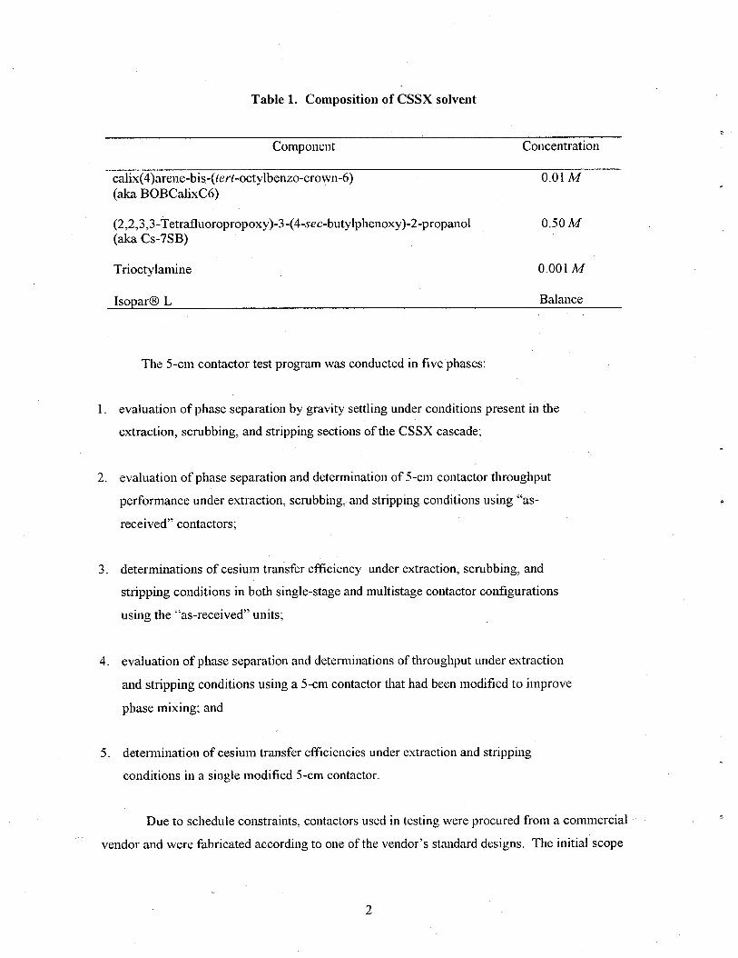
Table 1. Composition of CSSX solvent
Component
calix(4)arene-bis-(tert-octylbenzo-crown-6) (aka BOBCalixC6)
Concentration
0.01 A4
(2,2,3,3-Tetrafluoropropoxy)-3-(4-sec-butylphenoxy)-:!-propanol (aka Cs-7SB)
0.50M
Trioctylamine 0.001 IL4
IsoparO L Balance
The 5-cm contactor test program was conducted in five phases:
1. evaluation of phase separation by gravity settling under conditions present in the
extraction, scrubbing, and stripping sections of the CSSX cascade;
2. evaluation of phase separation and determination Of %CJll contactor throughput
performance under extraction, scrubbing, and stripping conditions using “as-
received” contactors;
3. determinations of cesium transfer efficiency under extraction, scrubbing, and
stripping conditions in both single-stage and multistage contactor configurations
using the “as-received” units;
4. evaluation of phase separation and determinations of throughput under extraction
and stripping conditions using a 5-cm contactor that had been modified to improve
phase mixing; and
5. determination of cesium transfer effkiencies under extraction and stripping
conditions in a single modified 5-cm contactor.
Due to schedule constraints, contactors used in testing were procured from a commercial
vendor and were fabricated according to one of the vendor’s standard designs. The initial scope
R
2

of the test program consisted of items 1, 2, and 3, with each step being a prerequisite to the
succeeding work.
Observations of flow patterns within the contactor made during task 2 indicated that
mixing of solutions in the as-received contactors was limited. This limitation was apparently due
to a design feature that the vendor added specifically to increase contactor throughput and reduce
mixing in the region between the rotor and the stationary housing. (The vendor’s target
application is the separation of emulsions, including the recovery of crude and refined oils from
spills into waterways.) Mass transfer results obtained from task 3 confirmed that phase mixing in
the as-received contactors was inadequate. Consequently, the decision was made to modify a
contactor to improve phase mixing and to repeat single-stage mass transfer tests using the
modified device. Because the modifications affected contactor hydraulics, throughput
determinations for the modified apparatus were necessary prior to performing mass transfer
testing.
’ Only tasks 1,4, and 5 are reported in this document; results from tasks 2 and 3 are
presented only where needed for comparison. The decision to exclude discussion of tasks 2 and 3
from this report was based on the atypical configuration of the contactor used in these tests. Use
of a contactor design in a CSSX process deployment that incorporates any feature intended to
minimize phase mixing is contrary to the goal of the process. Furthermore, the specific atypical
feature of the vendor-supplied devices-a housing bottom plate with curved vanes that arc
located in the space below the r&or-is a deviation from all prior contactor designs produced at
Argonne National Laboratory (ANL), ORNL, and SRS. Therefore, to accurately compare results
from the subject effort with those obtained in concurrent tests using 2-cm contactors, only results
obtained using modified 5-cm contactors should be considered.
2. EXPERIMENTAL PROGRAM
All throughput testing was performed using a single contactor configured for constant
recycle of aqueous and organic solutions, as shown in Fig. 1. All mass transfer testing was
performed using a single contactor configured for once-through processing of feed solutions, as
indicated in Fig. 2.
Equipment used in determinations of dispersion numbers under gravity settling, which
consisted of standard laboratory glassware and a stopwatch, is not described in any detail in this
report. Detailed equipment.descriptions presented in this section of the report are applicable to
3

Sample
‘r T
Sample/drain -!-
Centrifugal Contactor
H Sample
Organic supply pump C
Aqueous feed pump
Fig. 1. Equipment configuration for contactor throughput determinations.
4

Centrifugal Contactor
, u
Aqueous feed pump
z t %
* Sample
4 Sample
I
% Sample/drain
Organic feed pump
-
Aqueous effluent tank
. Fig. 2. Equipment configuration for single-stage mass transfer testing.
Y 5
testing performed using the modified contactor. Modified contactor tests utilized positive-
displacement metering pumps for transfer of solutions from feed tariks to the contactor. This
equipment selection represents a change from preceding 5-cm CSSX tests (tasks 2 and 3) in
which flows were delivered by means of centrifugal pumps and flow rates were monitored and
controlled uSing rotameters with integral needle valves. The change in equipment, made to
achieve greater feed stream flow precision, was implemented after dificulty was experienced
maintaining steady flow rates at low-end values using the centrifugal pump/rotameter/valve
scheme.
2.1 EQUIPMENT
2.1.1 Centrifugal Contactor
Centritigal contactors used in testing were obtained from CINC, Inc. (Carson City, NV)
as a standard-design item (model V-2). Of the four contactor units available for use in the subject
test program, one had been used in work prior to the CSSX demonstration effort. That particular
unit was equipped with a transparent window located in $e mixing zone of the contactor housing.
Because of concerns regarding mixing, this unit was used in all throughput and single-stage mass
transfer testing to permit direct observation of flow behavior in the mixing zone.
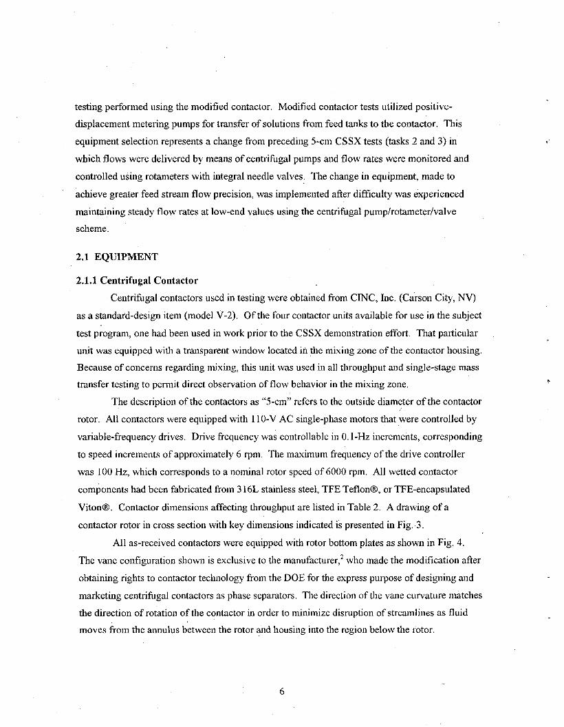
The description of the contactors as “5-cm” refers to the outside diameter of the contactor
rotor. All contactors were equipped with 11 O-V AC single-phase motors that kere controlled by
variable-frequency drives. Drive frequency was controllable in 0. l-Hz increments, corresponding
to speed increments of approximately 6 rpm. The maximum frequency of the drive controller
was 100 Hz, which corresponds to a nominal rotor speed of 6000 rpm. All wetted contactor
components had been fabricated from 3 16L stainless steel, TFE Teflon@, or TFE-encapsulated
Vito&. Contactor dimensions affecting throughput are listed in Table 2. A drawing of a
contactor rotor in cross section with key dimensions indicated is presented in Fig. 3.
All as-received contactors were equipped with rotor bottom plates as shown in Fig. 4.
The vane configuration shown is exclusive to the nlanufacturer,2 who made the modification after
obtaining rights to contactor technology from the DOE for the express purpose of designing and
marketing centrifugal contactors as phase separators. The direction of the vane curvature matches
the direction of rotation of the contactor in order to minimize disruption of streamlines as fluid
moves from the annulus between the rotor and housing into the region below the rotor.
6

Table 2. Key dimensions of CINC model V-2 (5-cm) centrifugal contactor
Designation Description Dimension (in.)” Dimension (mm)
RSA Aqueous weir radius 0.4875 12.383 RSO Organic weir radius 0.408 10.355
. RT Rotor inlet radius 0.200 5.076b RU Underflow radius 0.875 22.208 RC Outside underflow radius 0.938 23.807 BO Height of separating zone 4.190 106.345 BA Height of aqueous channel 0.400 10.152 HA0 Height between weirs 0.668 16.954 DRC Rotor/housing gap radius 0.250 6.345 THETA Angle between under-flows
‘Unless designated otherwise. 38” _., .x.
bDimension as received from the vendor. This dimension was increased to 9.61 mm to convert the contactor to the partially pumping mode.
After observing limited liquid holdup in the mixing zone of the as-received contactor and
after obtaining unacceptable mass transfer results, modifications were made to improve phase
mixing. First, a housing bottom cap with straight radial vanes was fabricated to replace the
vendor-supplied component (refer to Fig. 5). Second, the opening in the bottom of the rotor
through which the dispersed phases enter the rotor was enlarged from 5.076 to 9.610 mm to
increase liquid holdup in the contactor mixing zone. Increased mixing zone holdup is obtained
when the size of the rotor opening is increased sufficiently to change the contactor operating
mode from fully to partially pumping.
In the fully pumping mode, the hydraulic force required to move fluids through the rotor
is generated entirely by the rotor acting on the resident fluid. In this mode of operation, fluid
flows from the mixing zone into the rotor and is immediately forced away from the opening so
that a column of air is present coincident with the rotor’s centerline and extending from the
bottom of the rotor to the organic weir. The diameter of this air column just inside the rotor is
greater than the diameter of the rotor opening. Because fluid entering the rotor moves
immediately toward the wall, there is little, if any, back mixing of the liquids from the mixing
zone into the separating zone of the contactor.
In the partially pmnping mode, the contactor is operated so that the force generated by the
rotor is not sufficient to “lift” solutions from the rotor inlet to the discharge ports. This condition
can be induced by increasing the size of the rotor opening. When the rotor opening is enlarged
. beyond a certain value (depending on other contactor parameters), the mass inventory that can be
supported at the bottom of the rotor is not adequate to produce the required lift (head) when
accelerated by the turning of the rotor. Consequently, liquid accumulates in the rotor and the
7
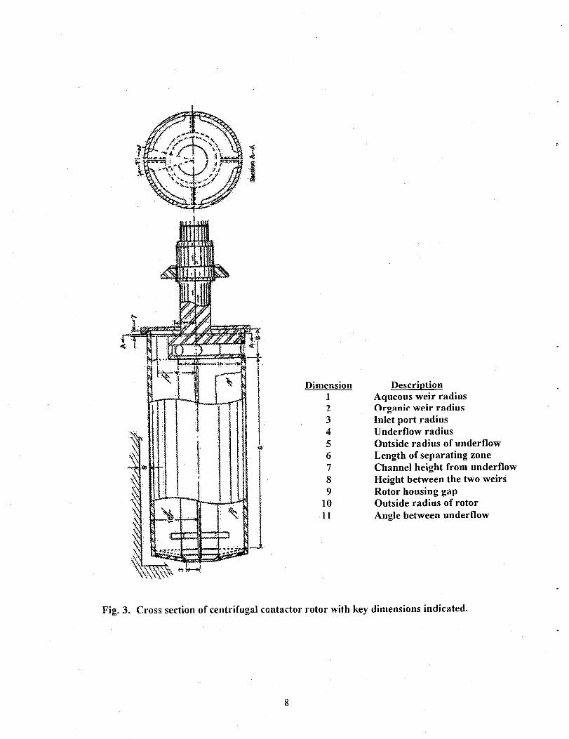
Dimension Descriution 1 Aqueous weir radius 2 Organic weir radius 3 Inlet port radius 4 Underflow radius 5 Outside radius of underflow 6 Length of separating zone 7 Channel height from underflow 8 Height between the two weirs 9 Rotor housing gap
10 Outside radius of rotor 11 Angle between underflow
Fig. 3. Cross section of centrifugal contactor rotor with key dimensions indicated.
8

.
Fig. 4. Photograph of contactor housing bottom as received from vendor.
Fig. 5. Photograph of contactor housing bottom after modification.
9
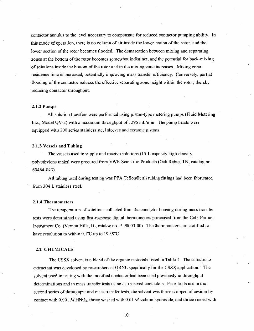
contactor annulus to the level necessary to compensate for reduced contactor pumping ability. In
this mode of operation, there is no column of air inside the lower region of the rotor, and the
lower section of the rotor becomes flooded. The demarcation between mixing and separating
zones at the bottom of the rotor becomes somewhat indistin’ct, and the potential for back-mixing
of solutions inside the bottom of the rotor and in the mixing zone increases. Mixing zone e
residence time is increased, potentially improving mass transfer efficiency. Conversely, partial
flooding of the contactor reduces the effective separating zone height within the rotor, thereby
reducing contactor throughput.
2.1.2 Pumps
All solution transfers were performed using piston-type metering pumps (Fluid Metering
Inc., Model QV-2) with a maximum throughput of 1296 mL/min. The pump heads were
equipped with 300 series stainless steel sleeves and ceramic pistons.
2.1.3 Vessels and Tubing
The vessels used to supply and receive solutions (15-L capacity high-density
polyethylene tanks) w,ere procured from VWR Scientific Products (Oak Ridge, TN, catalog no.
60464-043).
All tubing used during testing was PFA Teflon@; all tubing fittings had been fabricated
from 304 L stainless steel.
2.1.4 Thermometers
The temperatures of solutions collected from the contactor housing during mass transfer
tests were determined using fast-response digital thermometers purchased from the Cole-Parmer
Instrument Co. (Vernon Hills, IL, catalog no. P-90003-00). The thermometers are certified to
have resolution to within O.l”C up to 199.9”C.
2.2 CHEMICALS
The CSSX solvent is a blend of the organic materials listed in Table 1. The calixarene
extractant was developed by researchers at ORNL specifically for the CSSX application.’ The
solvent used in testing with the modified contactor had been used previously in throughput
determinations and in mass transfer tests using as-received contactors. Prior to its use in the
second series of throughput and mass transfer tests, the solvent was thrice stripped of cesium by
contact with 0.00 1 M HN03, thrice washed with 0.0 1 A4 sodium hydroxide, and thrice rinsed with
10

demineralized water, Samples of the solvent were collected. and were processed through a series
of cesium extractions, acid scrubs, and dilute acid strips by ORNL Chemical and Analytical
Sciences Division personnel to verify the effectiveness of the wash procedure. Cesium
distribution results from the sample analysis were consistent with results obtained using virgin
CS SX solvent.
Scrub (0.05 MHN03) and strip (0.001 MHN03) aqueous solutions were formulated
using 0.10 NHNO, procured from J. T. Baker Co. and diluted with water that had been deionized
using a Bamstead NanopureB filtration system. Sodium hydroxide solutions used to wash the
solvent were formulated using a standard 0.1 N sodium hydroxide solution (ACS reagent grade,
procured from the J. T. Baker Co.).
SRS waste supematant simulant was formulated according to SRS procedure WSRC-RP-
2000-00361, Rev. 0, and had the composition listed in that document for “average” SRS
supematant simulant.3 The nominal cesium concentration in all simulant batches used in testing
was 0.000 14 M.
2.3 EXPERIMENTAL PROCEDURES .
2.3.1 Determination of Dispersion Number
. Dispersion numbers were determined under extraction, scrubbing, and stripping
conditions, with and without the presence of cesium. In all tests, phase volumes proportional to
the flow rates of the solvent, scrub, and strip solutions in the CSSX flowsheet were placed into a
lOO-mL graduated Pyrex@ cylinder. The position of the interface was recorded. After a ground
glass stopper was placed into the cylinder, the solutions were agitated for 20 s; agitation was
suspended for 10 s and then resumed for anadditional 20 s. (The method of intermittent agitation
was selected based on published data indicating that it is a more effective means of dispersing
immiscible phases than is continuous agitation4) At the end of the second agitation, a stopwatch
was started and the time required for the interface to return to its original position was recorded.
The total height of the dispersion within the cylinder was measured. (In all cases, the dispersion
band immediately after the second agitation period was the total liquid height in the cylinder.)
Dimensionless dispersion numbers were calculated according to the expression .
.
11
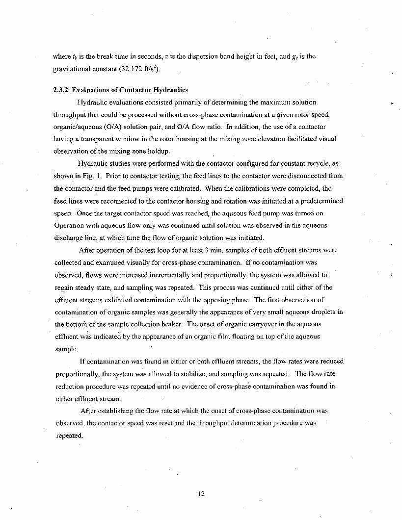
where tb is the break time in seconds, z is the dispersion band height in feet, and g, is the
gravitational constant (32.172 Ws2).
__ 2.3.2 Evaluations of Contactor Hydraulics
Hydraulic evaluations consisted primarily of determining the maximum solution
throughput that could be processed without cross-phase contamination at a given rotor speed,
organic/aqueous (O/A) solution pair, and O/A flow ratio. In addition, the use of a contactor
having a transparent window in the rotor housing at the mixing zone elevation facilitated visual
observation of the mixing zone holdup.
Hydraulic studies were performed with the contactor configured for constant recycle, as
shown in Fig. 1. Prior to contactor testing, the feed lines to the contactor were disconnected from
the contactor and the feed pumps were calibrated. When the calibrations were completed, the
feed lines were reconnected to the contactor housing and rotation was initiated at a predetermined
speed. Once the target contactor speed was reached, the aqueous feed pump was turned on.
Operation with aqueous flow only was continued until solution was observed in the aqueous
discharge line, at which time the flow of organic solution was initiated.
After operation of the test loop for at least 3bmin, samples of both effluent streams were
collected and examined visually for cross-phase contamination. If no contamination was
observed, flows were increased incrementally and proportionally, the system was allowed to
regain steady state, and sampling was repeated. This process was continued until either of the
effluent streams exhibited contamination with the opposing phase. The first observation of
contamination of organic samples was generally the appearance of very small aqueous droplets in
the bottoln of the sample collection beaker. The onset of organic carryover in the aqueous
effluent was indicated by the appearance of an organic film floating on top of the aqueous
sample.
If contamination was found in either or both effluent streams, the flow rates were reduced
proportionally, the system was allowed to stabilize, and sampling was repeated. The flow rate
reduction procedure was repeated until no evidence of cross-phase contamination was found in
either effluent stream.
After establishing the flow rate at which the onset of cross-phase contamination was
observed, the contactor speed was reset and the throughput determination procedure was
repeated.
12

,
2.3.3 Mass Transfer Evaluations
Mass transfer determinations using the modified contactor were performed using a single
device configured for once-through processing of feed solutions, as indicated in Fig. 2. Testing
was limited to use of a single contactor to permit extended operation with a limited quantity of
solvent, thereby increasing the likelihood that steady state would be reached prior to sampling.
Results from multistage testing using the as-received contactors indicated that steady state was
not achieved after a period of operation equal to three system residence times. The data obtained
were insufficient to confirm that steady state was reached after five residence times.
Mass transfer testing with the modified contactor was performed under conditions present
in the extraction and stripping sections of the CSSX cascade. Both extraction and stripping tests
were performed at a rotor speed of 3600 rpm. Two sets of flow conditions were applied in each
phase of testing. The first sets flow conditions that were applied in extraction and stripping tests
were proportional to the relative flows in the extraction and stripping sections that are called for
in the baseline CSSX fu1l-caScad.e floursheet. ..1.. _+. .., I Testing was initiated by starting the contactor, followed by initiation of aqueous solution
feed. Once flow was observed in the aqueous discharge line, both the flow of organic and the
experiment clock were started.
. During extraction testing, samples were collected at 4 and 6 min after initiation of
organic phase flow. Due to the decreased flow rates applied during strip testing, samples were
collected 8 and 10 min after starting the organic-phase flow. Following collection of the second
set of samples for each set of test conditions and with the rotor turning, approximately 50 mL of
solution was drained from the contactor through a valve connected to the housing bottom. The
temperature of this solution was measured immediately. Temperature measurement? were not
taken during the first sampling under each condition set to avoid upsetting the system between
samplings.
.
Prior to the stripping test, the organic solution from the extraction test was twice
scrubbed with 0.05 M HNO3, using the modified contactor in order to adjust the pH of the extract
in preparation for stripping. Following scrubbing, the contactor was dismantled, rinsed with
demineralized water, and dried to prevent contamination of the stripping-condition test.
To determine the efficiency of the contactor, the collected samples were divided into two
volumes. Aliquots of aqueous and organic effluents from each sampling were contacted in
proportions equal to the relative flow rates. The samples were placed in sealed cuvettes. They
were then submerged in a controlled temperature water bath that was set at the contactor solution
temperature measured after the second sampling from each test condition. After equilibrating
13

thermally for at least 15 min, the cuvettes were agitated manually for two 20-s intervals with an
intermediate 10-s hold period. AFter agitation, the samples were placed back into the water bath
and allowed to separate under gravity. After at least a IO-min period of separation, the cuvettes
were placed in a laboratory centrifuge to obtain complete phase separation. After centrifugation
the cuvettes were placed back into the water bath for at least 5 min prior to collection of samples.
Both equilibrated and as-collected samples were analyzed for cesium by inductively coupled
plasma (ICP) mass spectrophotometry.
Mass transfer efficiencies were calculated using the Murphree definition based on the
organic-phase concentrations,
v = Y-Yin xl00 , Y”‘] - Yin
where y is the cesium concentration of the organic effluent, yin is the inlet organic cesium
concentration, andy,, is the cesium concentration of the organic effluent after equilibration.
3. RESULTS
3.1 DISPERSION NUMBER
Results of the dispersion number determinations are summarized in Table 3. As
the table indicates, dispersion numbers were determined with and without the presence of cesium.
The results indicate an increase in dispersion number with the addition of cesium under extraction
conditions and decreases in AJ’D~ when cesium was present under scrubbing and stripping
conditions. Because the minute concentrations of cesium present are unlikely to affect surface
properties significantly, the differences are most likely the result of inherent inaccuracy in the
determination of break time. (Break time determinations are prone to inaccuracy because of the
qualitative nature of the end point.) In addition, during the reported test effort, it was found that
break time was affected by the method of agitation (i.e., continuous versus interrupted), with the
latter producing long separation times. More significant than the minor variations in NUT values is
the fact that all values are sufficiently high to result in satisfactory phase separation in solvent
extraction processes, based on prior experience.5
14
.
.
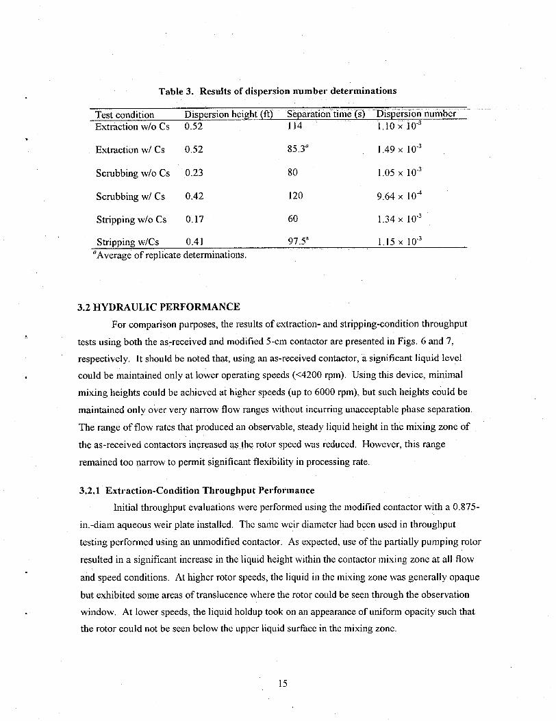
Table 3. Results of dispersion number determinations
- .“_ .,.“. -I Test condition Dispersion height (ft) Separation time (i) “Iiis@%iZi~ number Extraction w/o Cs 0.52 114 1.10 x IO”
Extraction wl Cs 0.52 85.3” 1.49 x 10”
Scrubbing w/o Cs 0.23 80 1.05 x 10”
Scrubbing wl Cs 0.42 120 9.64 x lOA
Stripping w/o Cs 0.17 60 1.34 x 1oe3
Stripping w/Cs 0.41 ‘Average of replicate determinations.
97.5” 1. I5 x 10”
3.2 HYDRAULIC PERFORMANCE
For comparison purposes, the results of extraction- and stripping-condition throughput
tests using both the as-received and modified 5-cm contactor are presented in Figs. 6 and 7,
respectively. It should be noted that, using an as-received contactor, a significant liquid level
could be maintained only at lower operating speeds (~4200 rpm). Using this device, minimal
mixing heights could be achieved at higher speeds (up to 6000 rpm), but such heights could be
maintained only over very narrow flow ranges without incurring unacceptable phase separation.
The range of flow rates that produced an observable, steady liquid height in the mixing zone of
the as-received contactors increased as.the rotor speed was reduced. However, this range
remained too narrow to permit significant flexibility in processing rate.
3.2.1 Extraction-Condition Throughput Performance
Initial throughput evaluations were performed using the modified contactor with a 0.875-
in.-diam aqueous weir plate installed. The same weir diameter had been used in throughput
testing performed using an unmodified contactor. As expected, use of the partially pumping rotor
resulted in a significant increase in the liquid height within the contactor mixing zone at all flow
and speed conditions. At higher rotor speeds, the liquid in the mixing zone was generally opaque
but exhibited some areas of translucence where the rotor could be seen through the observation
window. At lower speeds, the liquid holdup took on an appearance of uniform opacity such that
the rotor could not be seen below the upper liquid surface in the mixing zone.
15

1400
1200
1000
400
200
0
l Standard rotor, 0.875-in.-diam aqueous weir
I Modified rotor, 0.950-in-diam aqueous weir 0
l
0 1000 2000 3000 4000
Rotor speed (rpm)
5000 6000 7000
Fig. 6. Throughput results for 5-cm centrifugal contactor under extraction conditions.
l Standard rotor, 0.87%in.-diam aqueous weir
S Modified rotor, 0.950~in-diam aqueous weir
1000 2000 3000 4000
Rotor speed (x-pm)
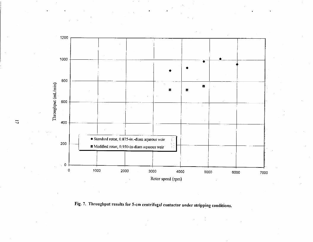
Fig. 7. Throughput results for 5-cm centrifugal contactor under stripping conditions.
The first evaluation using the modified contactor was performed at 6000 rpm with
organic and aqueous phase flow rates of 80 and 235 mL/min, respectively. With aqueous-only
feed, the liquid height in the mixing zone was about one-third the distance between the rotor
bottom and the organic collection ring. Shortly after organic flow was established liquid was
observed over the entire height of the mixing zone that was visible through the housing window.
No foaming was observed in either of the discharge lines from the contactor. A single droplet of
aqueous carryover was found in a sample of organic effluent; there was no organic-phase
carryover in the aqueous effluent. With the rotor turning at 6000 rpm, the flow rates of organic
and aqueous phases were reduced first to V. = 75 mL/min and VA = 2 15 mL/min, then to V. = 62
mL/min and V, = 18 1 mL/min. Aqueous effluent samples collected at both conditions showed no
evidence of contamination with the organic solvent. Droplets of aqueous contamination were
found in samples of organic effluent collected under both sets of conditions, and successive
organic-phase samples collected at each condition showed gradual increases in the level of
contamination.
Subsequently, effluent samples were collected at a range of flow conditions and at rotor
speeds ranging from 2400 to 6000 rpm. In all cases, the aqueous effluent was found to be free of
organic-phase carryover. However, in all cases there was evidence of aqueous-phase
contamination in the organic effluent. The degree of contamination ranged from a single aqueous
drop (diameter of = 1 mm) in approximately 50 mL of organic solution to >lO% carryover.
In an effort to shift the phase boundary inside the rotor radially outward (and increase the
residence time of the organic phase tiithin the separating zone), the aqueous weir plate was
replaced with one having a diameter of 0.950 in. After replacing the weir plate, contactor
operation was resumed at a rotor speed of 3600 rprn with aqueous and organic phase flows of 375
and 115 mL/min, respectively. The test loop was operated for approximately 3 min prior to
sampling to attain steady state. No cross-phase contamination was seen in samples collected
from the two effluent streams. All subsequent throughput evaluations using the partially pumping
’ rotor were performed with an aqueous weir diameter of 0.950 in.
At 3600 rpm, flow rates were increased to 160 mL/min of solvent and 490 mL/min of
aqueous solution with no indication of effluent contamination. When the flows were increased
proportionally above these values, aqueous contamination of the organic effluent was observed.
Acceptable separation performance was reestablished by returning flow rates to VA = 490 mL/min
and V. = 160 mLlmin
18
Testing at 4200 rpm was initiated at aqueous and organic flow rates of 490 and
160 mL/min, respectively. Effluent samples collected after the system was allowed to reach
steady state were free of cross-phase contamination. Attempts were made to operate at flow rates
that were increased proportionally from the initial values. In all cases, aqueous carryover was
found in organic effluent samples. As occurred at the 3600~t-pm rotor speed, good phase
separation was reestablished when the flows were reset to V, = 490 and V. = 160.
Attempts were made to operate the contactor at a rotor speed of 4800 rpm, using flow
conditions that had produced good separation results at both 3600 and 4200 rpm. In all cases,
aqueous contamination was observed in organic effluent samples.
In an attempt to reestablish acceptable separation performance (i.e., clear the contactor),
the flows to the device were terminated and the rotor speed was increased to 6000 rpm. When
flow from the contactor stopped, the contactor motor was turned off and the rotor and rotor
housing were drained. To verify previous results, the contactor was operated at 3600 rpm with
VA = 375 mL/min and V. = 115 mL/min. Both effluent streams were free of opposing-phase
carryover. The rotor speed was then increased to 4200 rpm and the maximum flow conditions
established earlier at this speed (VA = 490 mL/min and V. = 160 mL/min) were successfklly
verified. Another attempt was made to separate the phases at a rotor speed of 4800 rpm with VA
= 490 mL/min and V. = 160 mL/min. As had occurred previously, signifkant carryover of
aqueous solution (> 1%) was seen in the organic discharge stream. Subsequent sample collections
at reduced flow conditions (VA = 260 mL/min and VO = 95 mL/min) resulted in findings of
continued aqueous-phase carryover in the organic effluent from the contactor. Carryover at these
flow conditions was eliminated after stopping the contactor, draining the rotor and housing, and
restarting at 3000 rpm.
Finally, to verify operational stability as a prerequisite for follow-on mass transfer
testing, the contactor was operated at a rotor speed of 3600 rpm for 20 min at VA = 490 mL/min
and V. = 160 mL/min. Acceptable performance was maintained throughout the test period under
these conditions.
3.2.2 Stripping Couditiou Throughput Performauce
Because of to the similarities bet&ken scrubbing and stripping conditions in the CSSX
flowsheet and because follow-on mass transfer testing was to be performed only under extraction
and stripping conditions, throughput testing of the modified contactor was not performed under
scrubbing conditions. Prior to stripping-mode throughput tests, the system was rinsed with
deionized water. A sample of the rinse water used was determined to have a pH value of
19
approximately 10. After the water rinse, the system was flushed with CSSX scrub solution (i.e.,
\ 0.05 MHN03). After the system was rinsed for about 6 min, the aqueous discharge stream was
determined to have a pH of approximately 3. At this point, rinsing was terminated and the
aqueous solution in the test loop was replaced with CSSX strip acid (0.001 MHN03).
No entrainment was found in either effluent stream when the contactor was operated at
3600 rpm with flow conditions VA = 90 mL/min and V. = 450 mL/min. No cross-phase
contamination was observed at flow rates up to VA = 120 mL/min and V. = 600 mL/min.
However, at VA = 130 mL/min and V. = 650 mL/min, an organic film appeared on the surface of
the samples of aqueous effluent. The organic film became more apparent when the flows were
increased to VA = 140 mL/min and V. = 700 mL/min.
To test the ability of the partially pumping rotor to recover from undesirable operating
conditions, the organic flow to the contactor was terminated. Aqueous samples collected for up
to 5 min after termination of the solvent flow retained an organic film layer.
At 4200 rpm with flow rates VA = 120 mL/min and V. = 600 mL/min, both the aqueous
and organic effluent streams were free of contamiuation. As was the case at 3600 rpm, an
organic film appeared on the surface of aqueous eMuent samples collected at flow rate conditions
V, = 130 mL/min and V. = 650 mL/min.
To clear the aqueous contactor flow path of solvent prior to testing at 4800 rpm, the flow
of organic to the contactor was suspended while contactor operation was continued for
approximately 3 min. The rotor speed was increased to 4800 rpm, and flow rates were set at VA =
120 mL/min and Vo = 600 mL/min. No contamination was observed in samples collected from
the two effluent streams. The same result was obtained after increasing the flow rates to
VA = 125 mL/min and V. = 630 mL/min. An organic film appeared on the surface of aqueous
effluent samples collected after the flows had been increased to VA = 130 mL/min and
Vo = 650 mL/min. Recovery was accomplished by suspending the flow of solvent to the
contactor.
3.2.3 Summary of Throughput Determination and Hydraulic Performance Results
Results of the throughput testing using the CINC 5-cm contactor indicate that the phase
separation aspects of the device perform very well in the CSSX application. However, as the data
in Figs. 6 and 7 indicate, throughput capacity was significantly reduced when the partially
” pumping rotor was used.
Using the fully pumping (as-received) rotor, the primary limitation to increased
throughput was the accumulation of foam in the organic discharge line, particularly under
20
.
extraction and scrubbing conditions. Observations made during testing with this rotor indicated
that the foam consists entirely of the solvent and is generated in the upper region of the
contactor-possibly by the impact of solvent against the wall of the organic collection trough
after it exits the rotor. Reducing flow through the contactor was found to eliminate foaming. It
was also found determined that maximum flows could be increased without foam backup from
the organic discharie line into the contactor mixing zone by sloping the line downward from the
contactor outlet connection.
Due to a reduced tendency toward foaming, phase separation performance using the as-
received contactor under stripping conditions was more robust than indicated for extraction and
scrubbing conditions. Throughput capacities using this unit under stripping conditions were
consistently higher than capacities under scrubbing conditions. A review of test observations
indicates that the limiting factor preventing scrubbing-mode operation under conditions that
produced acceptable stripping-mode phase separation was the appearance and accumulation of
organic-phase foam.
Extraction-mode throughput testing using a partially pumping rotor was initially plagued
by aqueous-phase contamination in the organic effluent. Numerous attempts to obtain acceptable
phase separation by changing the rotor speed and the solution feed rates were unsuccessful. Once
it became apparent that the residence time of the organic phase within the separating zone was
insufficient (probably due to the loss of effective separation height resulting from partial-pumping
operation), an aqueous weir with a larger opening was installed. This modification caused a shift
in the phase boundary within the rotor away from the organic weir and successfully eliminated
organic effluent contamination under many flow conditions.
Excellent mixing zone heights were observed under all flow conditions applied during
throughput tests using the partially pumping rotor. As a result of the modification, mass transfer
operations could be performed at very low tlow rates without apparent loss of mixing capability.
As expected, flow capacities were significantly reduced in the partially pumping condition. Two
significant differences between results obtained with a fully pumping rotor and those achieved
with a partially pumping device are apparent. First, the chief limiting factor under extraction
conditions with a partially pumping rotor appears to be phase separation within the rotor. In the
fully pumping mode, extraction throughput was usually limited by foam formation outside the
rotor. Second, recovery from unfavorable flow and speed conditions using the partially pumping
rotor was slow when attempted by resetting flows and speeds to proven values. More rapid
recovery required termination of the org‘anic flow. After extreme upset conditions, recovery was
accomplished by stopping all flows and draining the contactor. This process was necessary
21
because of the extremely long times required to reestablish acceptable phase separation under
continuous contactor operation.
Under extraction and stripping conditions, the fully pumping (i.e., as-received) contactor
exhibited both greater processing capacity and greater responsiveness to increased rotor speed.
The first result is expected because the loss of separation height resulting from partial-pumping
operation significantly affects the ability of the contactor to provide adequate phase separation as
throughput increases. In addition, reduced pumping efficiency in the partially pumping contactor
limits the extent to which increased rotor speed can affect throughput.
3.3 MASS TRANSFER PERFORMANCE
As noted in Sect. 1, cesium transfer efficiencies obtained in tests using as-received
centrifugal contactors were below expected values and would not produce the degree of waste
decontamination required in the proposed SRS application. Observations made during both
throughput and mass transfer tests indicated a high probability that low mass transfer efficiencies
were the result of poor mass transfer conditions (i.e., phase mixing) and were not due to process
chemistry limitations. To offset the poor mixing performance observed in previous tests, the
contactor modifications described earlier in this report were made.
Because cesium mass transfer in the scrubbing section of the CSSX cascade is not a
process performance metric, mass transfer testing using the modified contactor was performed
under extraction and stripping conditions only. However, because of the adverse effect that
hydroxide carryover from extraction to’stripping can have on cesium distribution during
stripping, the extract was scrubbed with the standard CSSX scrub solution and pH adjustment
was verified prior to performance of the stripping test.
3.3.1 Extraction-Mode Testing
Aqueous feed for extraction-mode testing was produced by combining SRS waste
simulant with CSSX scrub solution in the proportion 20.1: 1.33, which reflects flow conditions in
the baseline CSSX flowsheet. Solvent used in mass transfer testing had been recovered from
previous mass transfer and hydraulic tests. The recovered solvent had been stripped three times
with 0.00 1 A4 I-IN03, washed three times with 0.0 1 M NaOH, and rinsed three times with
deionized water. Phase separation and cesium extraction performance of the washed solvent were
verified in laboratory-scale tests prior to its use in the supplemental test program. All system
components were thoroughly cleaned prior to mass transfer testing.
22

.
Contactor operation was initiated at 3600 r-pm. Flow of aqueous feed solution was started
at a rate of 484 mL/min. When aqueous solution began to exit the contactor, solvent flow was
initiated at 150 mL/min. Samples of the effluent streams were collected after 4 min of operation
and again after 6 min of operation. After the second sample set was collected, feed flows were
stopped and the contactor was partially drained with the contactor still operating. The
temperature of the solution collected was measured and recorded.
The metering pumps used to deliver the feed streams were reset to provide flows of
V, = 306 mL/min and Vo = 95 mL/min. Flows of aqueous and organic feed solutions were
reestablished in the same manner as before. Samples of both effluent streams were collected
8 min after resumption of solvent flow and again after 10 min of testing. As before, after the
second sampling, the flows were stopped, the contactor housing was partially drained, and the
temperature of the solution was measured and recorded.
Test results of extraction-mode testing are summarized in Table 4. The results indicate
highly effkient transfer of cesium under both sets of flow conditions applied during testing.
An attempt was made to isolate the effects of the two contactor modifications-partial
pumping rotor and housing vane design-on mass transfer performance. In order to separate
these variables, it was necessary to operate a partially pumping rotor with the as-received vane
configuration and to test a straight-vane housing bottom with a fully pumping rotor. Because of
changes in contactor designs, the straight-vane bottom fabricated for use with the partially
pumping rotor could not be used with a new fully pumping rotor. The newer rotor design is
slightly shorter than the earlier version. The resulting increase in the gap between the bottom
vanes from the older contactor design and the bottom of the newer-design rotor allows vortex
formation below the rotor to the extent that the vane/rotor combination will not pump.
Consequently, attempts to isolate the effects of configuration on mass transfer were abandoned.
3.3.2 Stripping-Mode Testing
Due to the adverse effect that hydroxide ion carryover has on cesium stripping efficiency,
the extract produced in the supplemental extraction-mode test was contacted twice with 0.05 A4
HN03 using the modified contactor operating at 3600 rpm. Flow rates maintained during
scrubbing were VA = 490 mL/min and Vc = 150 mL/min. The low scrubbing O/A ratio (relative
the normal CSSX scrub ratio of 5.0) was selected as means of ensuring that adequate extract
neutralization was obtained in a single contact stage.
Following scrubbing, the extract collected was moved to the organic feed position.
Aqueous solutions from the scrubbing operation were collected and prepared for disposal. The
23

aqueous feed and collection tanks were cleaned, and deionized water was placed into the feed
tank. Water was pumped to the contactor to rinse the feed lines and the aqueous feed pump. The
water in the aqueous feed tank was then replaced with approximately 4 L of 0.001 MHNOs.
Contactor operation was initiated at 3600 r-pm. Strip solution flow was started at
30 mL/min. After approximately 7 min, aqueous flow began to exit the contactor and the solvent
flow was started at a rate of 150 mL/min. Samples of effluent solutions were collected 8 min
after starting organic-phase flow and again after 10 min of testing. As in previous testing, flows
were stopped, the contactor was partially drained, and the temperature of the solution collected
was measured and recorded. Flows were reestablished in the previous manner with VA = 60
mL/min and Vo = 300 mL/min. Samples were collected at 4 and 5 min after the start of organic-
phase flow. Flows were terminated, and the temperature of the solution inside the contactor was
measured and recorded.
Test results are reported in Table 5. Mass transfer efficiencies obtained under the first set
of flow conditions are acceptably high. However, a significant reduction in mass transfer
efficiency is indicated when the flow rates are doubled. The very limited number of data points
precludes drawing any concrete conclusions regarding the loss in mass transfer efficiency.
3.4 ADDITIONAL OBSERVATIONS
3.4.1 Solvent Washing in the 5cm Contactor
At several points during the 5-cm contactor test effort, the solvent inventory was, washed
with sodium hydroxide prior to reuse. Hydraulic performance during each operation was very
good over O/A ratios ranging from 5.0 to I .O. While no attempt was made to determine the
maximum throughput of the contactor under solvent washing conditions, it was found that
washing conditions could be performed with consistent success at the same flows that were
applicable to solvent stripping.
3.4.2 Emulsion Formation i
In the process of determining flow rate maxima under stripping conditions, flow
parameters were established that resulted in inadequate phase separation as evidenced by cross-
phase contamination of one or both effluent streams. To recover from these upset conditions, the
contactor housing was drained. On every occasion, solution drained from the contactor housing
when the rotor was left in operation (at 3600 rpm) was an emulsion with a milky, opaque
appearance. Formation of the emulsion has also been reported by researchers performing
24

l ,I . e . 1
Table 4. Single-stage extraction-mode mass transfer results using a modified centrifugal contactor
Aqueous flow Organic flow Rotor speed Stage Aqueous Aqueous Organic effluent Equilibrated Effkiency’ Da (mL/min) (mL/min) (rpm) temperature (“C) effluent Cs effluent pH Cs cont. (ppm) organic phase
cont. (ppm) Cs cont. (ppm) 484 150 3600 23.8 1.75 13.58 l 39.4 44.1 88.8 22.5 484 150 3600 23.8 1.83 13.63 38.8 44.7 86.1 21.2 306 95 3600 23.5 1.52 13.63 40.3 44.4 90.3 26.5 306 95 3600 23.5 1.54 13.63 39.7 44.9 87.8 25.8
“Murphree efficiency, defined in Sect. 2.3.3.
Table 5. Single-stage stripping-mode mass transfer results using ? modified centrifugal contactor
Aqueous flow Organic flow Rotor speed Stage Aqueous Aqueous Organic effluent Equilibrated Effkiency” Des (mL/min) (mL/min) b-pm) temperature (“C) effluent Cs effluent pH Cs cont. (ppm) organic phase
cont. (ppm) Cs cont. (ppm) 30 150 3600 23.0 45.5 : 3.00 15.1 15.2 ‘100.7 0.33 30 150 3600 23.0 46.3 .’ 3.00 15 14.1 94.2 0.32 60 300 3600 23.3 46 : 2.98 18.7 15 74.8 0.41
\ 60 300 3600 23.3 49.1 - 2.99 18.3 15.4 79.8 0.37 “Murphree efficiency, defined in Sect. 2.3.3.
concurrent CSSX testing and has been observed in stripping effluents from 2-cm contactors. To
isolate the location of the emulsion in the contactor, conditions that had been found to produce an
emulsion were established. After establishing steady-state operation, the housing was drained.
Contactor operation was continued during draining so that the solution inventory inside the rotor
was not collected. After draining the housing (i.e., the contactor mixing zone), feed flows and
rotor operation were terminated and the unit was drained. The solution collected from the rotor
did not contain any evidence of an emulsion.
The conclusion to be drawn from the observations reported is that the centrifugal force in
the $-cm contactor operating under stripping conditions at 3600 rpm is sufficient to separate the
emulsion that tends to form under these conditions.
4. CONCLUSIONS AND RECOMMENDATIONS .
Acceptable phase separation and cesium mass transfer performance are attainable under
CSSX extraction and stripping conditions using a 5-cm centrifugal contactor operated in partially
pumping mode. However, the contactor throughput was found to be somewhat limited. Flow
rate conditions applied in extraction testing-organic flow of 150 mL/min and aqueous flow of
484 ml/mm--were near the limit that could be maintained for an extended period of operation.
At this solvent flow rate for CSSX operation in the 5-cm contactor, our results showed that the
CSSX process would stage efficiencies of 87.5 rt 1.5% for the extraction and 97 f 3% for the strip
section.
Limitations in equipment availability at the time of testing prevented separation of the
effects of the two contactor modifications that were made to improve phase mixing. Based on ’
prior experience with 5.5-cm contactors, it is very likely that replacement of the vendor-supplied
housing bottom plate with one having straight radial vanes (and with the appropriate gap between
rotor and vanes) will improve mixing, thus permitting high stage efficiencies to be obtained using
fully pumping contactors. A test program to verify this supposition should be completed before
the pilot plant design is finalized. If found to be satisfactory, operation of a contactor with a
conventional (straight) vane configuration in the fully pumping mode is preferable to partially
pumping operation, because the former affords increased throughput flexibility, more rapid
response to changes in control parameters, and faster recovery from off-normal operation.
Regardless of whether acceptable contactor performance in the fully pumping mode can
be realized, there is no reason to expect that custom-designed centrifugal contactors are required
for successful operation of a CSSX cascade. Instead, the reported test results indicate that a
26

commercial unit with only minor modifications and with the flexibility provided by
interchangeable aqueous weirs can provide the stage efficiencies needed to meet CSSX cesium / removal goals.
s
27

5. REFERENCES
1. P. V. Bonnesen, L. H. Delmau, B. A. Moyer, and R. A. Leonard, “A Robust Alkaline-Side CSEX Solvent Suitable for Removing Cesium from Savannah River High Level Wastes,” Solvent Extr. Ion Exch. 18(6), 1079- 1107 (2000).
2. D. H. Meikrantz et al., “Centrifugal Separator, ” U.S. Patent No. 5,762,800, June 1998.
3. R. A. Peterson, Preparation of Simulated Waste Solutions for Solvent Extraction Testing, WSRC-RP-2000-00361, Westinghouse Savannah River Company, Aiken S.C., May 2000.
4. T. R. Briggs, “Experiments on Emulsions III,“J. Phys. Chem. 24, 120-126 (1920).
5. R. A. Leonard, “Design Rules for Solvent Extraction,” Solvent Extr. Ion Exch. 17(3), 597-612 (1999).
28

1. 2-3. 4. 5.
. 6. 7. 8. 9. 10. 11. 12-15. 16. 17. 18. 19. 20. 21. 22. 23. 24. 25.
- 26. 27. 28. 29. . 30.
INTERNAL DISTR!BUTION
K. K. Anderson J. F. Birdwell, Jr. P. V. Bonnesen J. L. Collins R. L. Cummins, L. H. Delmau J. N. Herndon R. D. Hunt R. T. Jubin T. E. Kent L. N. Klatt D. D. Lee M. P. Maskarinec A. Mattus C. P. McGinnis L. E. McNeese B. A. Moyer K. E. Plummer F. V. Sloop, Jr. R. D. Spence B. B. Spencer J. F. Walker J. S. Watson ORNL Central Research Library Laboratory Records, RC Laboratory Records, OSTI
EXTERNAL DISTRIBUTION
3 1. J. T. Carter, Westinghouse Savannah River Company, P.O. Box 6 16, Buidling 704-3B, Aiken, SC 29808
32. D. Chamberlain, Argonne National Laboratory, Building 205, 9700 South Cass Avenue, Argonne, IL 60439
33. N. F. Chapman, Westinghouse Savannah River Company, P.O. Box 616, Buidling 704-3B, Aiken, SC 29808
34. C. Conner, Argonne National Laboratory, Building 205, 9700 South Cass Avenue, Argonne,
- 35
L 36
IL 60439
R. G. Edwards, Westinghouse Savannah River Company, P.O. Box 616, Buidling 704-3B, Aiken, SC 29808
S. D. Fink, Westinghouse Savannah River Company, P.O. Box 616, Building 773-A, Aiken, SC 29808
29
37. H. D. Harmon, Tank Focus Area Salt Processing Program, P.O. Box 616, Building 704-3N, Aiken, SC 29808
38. R. T. Jones, Westinghouse Savannah River Company, P.O. Box 6 16, Building 704-3N, Aiken, SC 29808
39. R. A. Leonard, Argonne National Laboratory, Building 205, 9700 South Cass Avenue, .
Argonne, IL 60439
40. J. W. McCullough, Jr., U.S. Department of Energy, Savannah River Operations Office, Bldg. 704-3N, Aiken, SC 29808
41. J. R. Noble-Dial, U.S. Department of Energy, Oak Ridge Operations Office, P.O. Box 2001, Oak Ridge, TN 3783 l-8620
42. Michael Norato, Westinghouse A&en, SC 29808
Savannah River Company, P.O. Box 616, Building 773-A,
43. Robert Pierce, Westinghouse Savannah River Company, P.O. Box 616, Building 773-A, Aiken, SC 29808
44. S. N. Schlahta, Tank Focus Area Salt Processing Program, P. 0. Box 616, Building 704-3N, Aiken, SC 29808
45. P. C. Suggs, U.S. Department of Energy, Savannah River Operations Of&e, P.O. Box A, Building 704-3N, Aiken, SC 29808
46. W. L. Tamosaitis, Westinghouse Savannah River Company, P.O. Box 616, Building 773-A, Aiken, SC 29808
47. M. Thompson, Westinghouse Savannah River Company, P.O. Box 616, Building 773-A, Aiken, SC 29808
48. T. A. Todd, Idaho National Engineering & Environmental Laboratory, Building 637, MS- 52 18, Idaho Falls, 1D 834415-52 18
49. G. Vandegrift, Argonne National Laboratory, Building 205, 9700 South Cass Avenue, ’ Argonne, IL 60439
50. Doug Walker, Westinghouse Savannah River Company, P.O. Box 616, Building 773-A, Aiken, SC 29808
51. Dennis Wester, Westinghouse Savannah River Company, P.O. Box 616, Building 773-A, Aiken, SC 29808
52. W. R. Wilmarth, Westinghouse Savannah River Company, P.O. Box 616, Building 773-A, Aiken, SC 29808
53. Tanks Focus Area Technical Team, c/o B. J. Williams, Pacific Northwest National Laboratory, P.O. Box 999, MSIN K9-69, Richland, WA 99352
: 30
54. Tanks Focus Area Field Lead, c/o T. P. Pietrok, U.S. Department of Energy, Richland Operations Office, P.O. Box 550, K8-50, Richland, WA 99352
55. Tanks Focus Area Headquarters Program Manager, c/o K. D. Gerdes, DOE Office of Science and Technology, 19901 Germantown Rd., 1154 Cloverleaf Building, Germantown, MD 20874-l 290
31